EP1514735A1 - Kamerafahrt und Verfahren zum Filmen - Google Patents
Kamerafahrt und Verfahren zum Filmen Download PDFInfo
- Publication number
- EP1514735A1 EP1514735A1 EP03020744A EP03020744A EP1514735A1 EP 1514735 A1 EP1514735 A1 EP 1514735A1 EP 03020744 A EP03020744 A EP 03020744A EP 03020744 A EP03020744 A EP 03020744A EP 1514735 A1 EP1514735 A1 EP 1514735A1
- Authority
- EP
- European Patent Office
- Prior art keywords
- hovercraft
- fan
- camera
- traveling
- tracking device
- Prior art date
- Legal status (The legal status is an assumption and is not a legal conclusion. Google has not performed a legal analysis and makes no representation as to the accuracy of the status listed.)
- Withdrawn
Links
- 238000000034 method Methods 0.000 title claims description 7
- 230000002093 peripheral effect Effects 0.000 claims abstract description 9
- 230000008878 coupling Effects 0.000 claims description 4
- 238000010168 coupling process Methods 0.000 claims description 4
- 238000005859 coupling reaction Methods 0.000 claims description 4
- 230000000087 stabilizing effect Effects 0.000 claims description 3
- 238000007664 blowing Methods 0.000 claims 1
- 239000003570 air Substances 0.000 description 19
- XLYOFNOQVPJJNP-UHFFFAOYSA-N water Substances O XLYOFNOQVPJJNP-UHFFFAOYSA-N 0.000 description 6
- 238000006073 displacement reaction Methods 0.000 description 3
- 239000012080 ambient air Substances 0.000 description 1
- 238000002485 combustion reaction Methods 0.000 description 1
- 238000004891 communication Methods 0.000 description 1
- 238000010276 construction Methods 0.000 description 1
- 230000001934 delay Effects 0.000 description 1
- 230000037213 diet Effects 0.000 description 1
- 235000005911 diet Nutrition 0.000 description 1
- 239000012530 fluid Substances 0.000 description 1
- 230000006870 function Effects 0.000 description 1
- 238000009434 installation Methods 0.000 description 1
- 238000005339 levitation Methods 0.000 description 1
- 239000000463 material Substances 0.000 description 1
- 230000035939 shock Effects 0.000 description 1
- 239000002689 soil Substances 0.000 description 1
- 230000006641 stabilisation Effects 0.000 description 1
- 238000011105 stabilization Methods 0.000 description 1
Images

Classifications
-
- B—PERFORMING OPERATIONS; TRANSPORTING
- B60—VEHICLES IN GENERAL
- B60R—VEHICLES, VEHICLE FITTINGS, OR VEHICLE PARTS, NOT OTHERWISE PROVIDED FOR
- B60R13/00—Elements for body-finishing, identifying, or decorating; Arrangements or adaptations for advertising purposes
- B60R13/08—Insulating elements, e.g. for sound insulation
- B60R13/0884—Insulating elements, e.g. for sound insulation for mounting around noise sources, e.g. air blowers
-
- B—PERFORMING OPERATIONS; TRANSPORTING
- B60—VEHICLES IN GENERAL
- B60R—VEHICLES, VEHICLE FITTINGS, OR VEHICLE PARTS, NOT OTHERWISE PROVIDED FOR
- B60R11/00—Arrangements for holding or mounting articles, not otherwise provided for
- B60R11/04—Mounting of cameras operative during drive; Arrangement of controls thereof relative to the vehicle
-
- B—PERFORMING OPERATIONS; TRANSPORTING
- B60—VEHICLES IN GENERAL
- B60R—VEHICLES, VEHICLE FITTINGS, OR VEHICLE PARTS, NOT OTHERWISE PROVIDED FOR
- B60R13/00—Elements for body-finishing, identifying, or decorating; Arrangements or adaptations for advertising purposes
- B60R13/08—Insulating elements, e.g. for sound insulation
- B60R13/0876—Insulating elements, e.g. for sound insulation for mounting around heat sources, e.g. exhaust pipes
-
- F—MECHANICAL ENGINEERING; LIGHTING; HEATING; WEAPONS; BLASTING
- F16—ENGINEERING ELEMENTS AND UNITS; GENERAL MEASURES FOR PRODUCING AND MAINTAINING EFFECTIVE FUNCTIONING OF MACHINES OR INSTALLATIONS; THERMAL INSULATION IN GENERAL
- F16M—FRAMES, CASINGS OR BEDS OF ENGINES, MACHINES OR APPARATUS, NOT SPECIFIC TO ENGINES, MACHINES OR APPARATUS PROVIDED FOR ELSEWHERE; STANDS; SUPPORTS
- F16M11/00—Stands or trestles as supports for apparatus or articles placed thereon ; Stands for scientific apparatus such as gravitational force meters
- F16M11/02—Heads
- F16M11/18—Heads with mechanism for moving the apparatus relatively to the stand
-
- F—MECHANICAL ENGINEERING; LIGHTING; HEATING; WEAPONS; BLASTING
- F16—ENGINEERING ELEMENTS AND UNITS; GENERAL MEASURES FOR PRODUCING AND MAINTAINING EFFECTIVE FUNCTIONING OF MACHINES OR INSTALLATIONS; THERMAL INSULATION IN GENERAL
- F16M—FRAMES, CASINGS OR BEDS OF ENGINES, MACHINES OR APPARATUS, NOT SPECIFIC TO ENGINES, MACHINES OR APPARATUS PROVIDED FOR ELSEWHERE; STANDS; SUPPORTS
- F16M11/00—Stands or trestles as supports for apparatus or articles placed thereon ; Stands for scientific apparatus such as gravitational force meters
- F16M11/20—Undercarriages with or without wheels
- F16M11/24—Undercarriages with or without wheels changeable in height or length of legs, also for transport only, e.g. by means of tubes screwed into each other
- F16M11/38—Undercarriages with or without wheels changeable in height or length of legs, also for transport only, e.g. by means of tubes screwed into each other by folding, e.g. pivoting or scissors tong mechanisms
-
- F—MECHANICAL ENGINEERING; LIGHTING; HEATING; WEAPONS; BLASTING
- F16—ENGINEERING ELEMENTS AND UNITS; GENERAL MEASURES FOR PRODUCING AND MAINTAINING EFFECTIVE FUNCTIONING OF MACHINES OR INSTALLATIONS; THERMAL INSULATION IN GENERAL
- F16M—FRAMES, CASINGS OR BEDS OF ENGINES, MACHINES OR APPARATUS, NOT SPECIFIC TO ENGINES, MACHINES OR APPARATUS PROVIDED FOR ELSEWHERE; STANDS; SUPPORTS
- F16M11/00—Stands or trestles as supports for apparatus or articles placed thereon ; Stands for scientific apparatus such as gravitational force meters
- F16M11/42—Stands or trestles as supports for apparatus or articles placed thereon ; Stands for scientific apparatus such as gravitational force meters with arrangement for propelling the support stands on wheels
-
- B—PERFORMING OPERATIONS; TRANSPORTING
- B60—VEHICLES IN GENERAL
- B60R—VEHICLES, VEHICLE FITTINGS, OR VEHICLE PARTS, NOT OTHERWISE PROVIDED FOR
- B60R11/00—Arrangements for holding or mounting articles, not otherwise provided for
- B60R2011/0042—Arrangements for holding or mounting articles, not otherwise provided for characterised by mounting means
- B60R2011/008—Adjustable or movable supports
- B60R2011/0085—Adjustable or movable supports with adjustment by rotation in their operational position
- B60R2011/0089—Adjustable or movable supports with adjustment by rotation in their operational position around three axes, i.e. universally mounted
-
- F—MECHANICAL ENGINEERING; LIGHTING; HEATING; WEAPONS; BLASTING
- F16—ENGINEERING ELEMENTS AND UNITS; GENERAL MEASURES FOR PRODUCING AND MAINTAINING EFFECTIVE FUNCTIONING OF MACHINES OR INSTALLATIONS; THERMAL INSULATION IN GENERAL
- F16M—FRAMES, CASINGS OR BEDS OF ENGINES, MACHINES OR APPARATUS, NOT SPECIFIC TO ENGINES, MACHINES OR APPARATUS PROVIDED FOR ELSEWHERE; STANDS; SUPPORTS
- F16M2200/00—Details of stands or supports
- F16M2200/04—Balancing means
-
- F—MECHANICAL ENGINEERING; LIGHTING; HEATING; WEAPONS; BLASTING
- F16—ENGINEERING ELEMENTS AND UNITS; GENERAL MEASURES FOR PRODUCING AND MAINTAINING EFFECTIVE FUNCTIONING OF MACHINES OR INSTALLATIONS; THERMAL INSULATION IN GENERAL
- F16M—FRAMES, CASINGS OR BEDS OF ENGINES, MACHINES OR APPARATUS, NOT SPECIFIC TO ENGINES, MACHINES OR APPARATUS PROVIDED FOR ELSEWHERE; STANDS; SUPPORTS
- F16M2200/00—Details of stands or supports
- F16M2200/08—Foot or support base
Definitions
- the invention relates to shots, particularly in cinematographic of TV.
- the invention relates more particularly to a traveling shot for cinematographic shooting and / or television.
- the invention aims to provide a tracking shot of new design, which avoids the mentioned drawbacks higher known travellings and that allows catches views over uneven terrain, on water and at sea, with great flexibility of movement and without require the installation of raceways.
- the invention relates to a traveling including a camera on a vehicle, tracking is characterized in that the vehicle includes a hovercraft.
- the apparatus of shooting is not critical. He can be invariably a camera, a camera for cinematographic shots or a camera of TV.
- the camera may be type with photosensitive medium or digital type.
- the vehicle is used to move the camera views. According to the invention, it comprises a hovercraft.
- Hovercrafts are well known in technical ("Air Cushioned Vehicles", Conference pronounced by Jean Bertin on January 23, 1963 - http://aernav.free.fr/Coussin/Vehicules_CA.html; "The hovercraft, What is it? - http://perso.wanadoo.fr/leslanders/aero/histo/histo%201.ht m).
- a hovercraft (or air cushion vehicle) comprises a platform under which a draft is blown to lift it.
- a first design includes hovercraft with full lift chamber.
- the platform overcomes a hull or bell returned, under which we breathe the air stream.
- the air blown under the bell escapes at the periphery thereof and a lift cushion or air mattress is thus formed under the bell.
- Another hovercraft design includes hovercraft in which the lift chamber includes a peripheral slot.
- the platform includes a peripheral slot pointing downwards. Air is blown into this slot to form a dynamic fluid peripheral web that helps maintain a cushion or lift air mattress beneath the platform.
- the hovercraft may be a hovercraft of the full lift chamber type, a hovercraft of the peripheral slot lift chamber type or any other known type of hovercraft.
- any means appropriate may be used to infuse the air with the hovercraft. It can include a fan coupled to a motor, according to the design usual hovercraft.
- the engine can be a electric motor or an internal combustion engine.
- the fan and its engine are mounted on the hovercraft, as it is usually the case for known hovercraft.
- the fan motor is preferably an electric motor to reduce the noise of hovercraft.
- the fan and its motor are located outside the hovercraft and the fan is connected to the hovercraft's hovering chamber by means of a suitable hose.
- the pipe In this form of Tracking according to the invention, the pipe must be flexible enough not to impede the displacement of the hovercraft. This embodiment of the invention allows to separate the fan and its engine, shooting zones, which allows to prevent the shots from being disturbed by the sound of the fan and its motor.
- the air necessary for levitation is provided by an air cylinder under pressure, embarked on the hovercraft.
- This form of embodiment of the invention has the advantage of generating little noise.
- the hovercraft may comprise a single air cushion or, alternatively, minus two air cushions.
- the optimum number of air cushions will depend on the dimensions of the traveling and the weight of the camera, additional material that he has to support and, where the number of operators it has to support. In the majority of cases, only one air cushion is sufficient.
- the shape and dimensions of the hovercraft must be adapted to support the camera and possibly one or more operators. They must therefore be adapted in each case particular, through routine work in the office studies.
- the hovercraft includes a platform on which the socket device is mounted of views.
- the platform is designed according to circumstances and it can be flat or not. She can be circular, oval or polygonal, for example square, rectangular, hexagonal or octagonal.
- Fixing the camera on the hovercraft can be made by any suitable means, commonly used on travellings.
- the apparatus of views (eg a camera) is hinged on an arrow connected to the hovercraft by means of a hinge.
- the arrow is for example articulated at the upper end of a fixed vertical mast to a substantially horizontal platform of the hovercraft, so that it can rotate in azimuth and in elevation.
- the camera is set at a end of the boom and is also steerable in azimuth and elevation.
- an operator Maneuvering the arm according to the instructions of a cameraman (the cameraman in Anglo-Saxon language).
- the platform the hovercraft can be arranged to support the operator and allow him to maneuver the boom.
- This variant of the invention is especially well suitable for shooting on rough terrain, water bodies or at sea.
- the cameraman may be on the platform.
- he is out of the hovercraft, for example in a studio from where he maneuver the camera by means of a radio link.
- the arrow is arranged to make it manoeuvrable by an operator located in outside the hovercraft platform.
- This variant of the invention is suitable when the catches of views are made on gently example in the street, in a public square, on a beach, in studio).
- the displacement of the hovercraft can be realized by any suitable means.
- the hovercraft is equipped with at least one handle for to move it over a surface.
- the handle is intended for be seized by a person on the said person surface to move the hovercraft over it according to the instructions received from the cameraman.
- the displacement of the hovercraft can be achieved by thrust, traction or rotation.
- the hovercraft includes several handles, for facilitate his movement by several people.
- the hovercraft is equipped with a fan to ensure its propulsion.
- This fan is advantageously orientable in azimuth.
- the hovercraft comprises a stabilizing flywheel.
- the steering wheel has the function of stabilizing the attitude of the hovercraft.
- the choice of the steering wheel, in particular its diameter and mass, as well as its rotational speed will depend on various parameters, in particular the dimensions of the hovercraft and the devices and people it embarks. Its characteristics must be determined in each particular case.
- the steering wheel can be coupled to an autonomous motor. It is preferred, according to an advantageous variant, to connect the steering wheel to the engine used to drive the lift fan of the hovercraft.
- the mechanical connection of the flywheel to the motor preferably comprises a retractable coupling member, to allow cutting and restore at will the flywheel connection to the engine.
- the tracking according to the invention presents the particularity of no longer requiring the establishment of a adequate path before use. It presents as advantages, a great ease of use, a great maneuverability and great flexibility of use.
- Tracking according to the invention can be used on all types of terrain, as well as on the water. he can especially be used in the city, on streets or on paved squares, in squares, on lawns as well on uneven soils such as meadows, fields and hills, glaciers.
- the absence of raceway makes it specially well suited for use in the studio, within buildings (for example houses or dwellings historical data) or within vehicles (eg inside planes, trains or boats).
- the tracking according to the invention is especially well suited for use on bodies of water, particularly lakes, rivers, rivers and at sea.
- the traveling according to the invention finds a application for photographic shooting fixed.
- the traveling according to the invention is well adapted with animated shots, especially with cinematographic views and television shots.
- the invention therefore also relates to a method traveling filming, in which a traveling comprising, in accordance with the invention, a camera on a hovercraft.
- the camera is invariably a movie camera or a video camera television.
- a hovercraft with at least one handle and one moves the hovercraft by means of said handle.
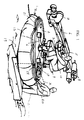
- the tracking shown in Figure 1 is specially adapted for cinematographic shooting or television. It includes a vehicle 1 carrying a platform 2.
- a mast 3 is fixed vertically to the platform 2 by means of a four-legged support. its upper end, the mast 3 carries an arrow 4.
- the arrow 4 is attached to the mast 3 via a articulation 5 appropriate to allow it to rotate in azimuth and elevation.
- a camera 7 is attached to one end of the arrow 4.
- arrow 4 is provided with a counterweight 8 used to balance the weight of the camera 7.
- the camera 7 is attached to the arrow 4 by through a joint (not shown), designed to orientate it in azimuth and elevation. This articulation is coupled to an engine (not shown), which can be maneuvered remotely by a cameraman located in a studio, using a radio link.
- the platform 2 also has an adjustable seat 9 for an operator schematized in 10.
- the operator 10 a mission to maneuver the arrow to steer it in azimuth and elevation according to instruction of the cameraman.
- the vehicle 1 is a air cushion vehicle or hovercraft.
- FIG. 2 shows, on a larger scale, a detail Hovercraft 1, designated by the notation reference numeral X in FIG.
- the hovercraft 1 is type with peripheral slot 11. This is delimited between a substantially horizontal plate 12 forming the base of vehicle 1 (or part of it) and a peripheral skirt 13.
- the peripheral skirt 13 is extended by a horizontal annular plate 14 which defines an annular chamber 15 in communication with the slot 11.
- An adequately profiled pipe 16 leads to the center of the room 15. It contains a fan 17, intended for draw ambient air and repress it under pressure, in the direction of arrow 18, in chamber 15. The passage of air through the slot 11 ensures the lift of the hovercraft above the ground 19.
- the tracking shown in Figure 1 can include a single air cushion, distributed substantially on its entire surface. Alternatively, it can understand several air cushions so distributed substantially uniform below its platform 2.
- the vehicle 1 comprises advantageously a stabilization wheel, no represent.
- the steering wheel serves to stabilize the position of the vehicle 1 above the ground 19, while the maneuver.
- the driving of the steering wheel is carried out at means of the motor (not shown) of the fan 17, to which it is connected by a coupling member appropriate.
- Said coupling member comprises a clutch intended to open the engine connection to flying, when the latter has reached its speed diet.
- the fan 17 is started so as to lift the vehicle 1 and the equipment it supports (as well as, the where appropriate, the operator 10) and ensure its sustenance above ground.
- one or more assistants (such as the one shown in 20) moves the vehicle 1 over 19.
- the vehicle is equipped with handles 21 on the periphery of the platform 2.
- the fan 17 and its motor are mounted on the hovercraft 1 and transported with it.
- the fan 17 and its engine are located outside hovercraft 1 and a flexible hose connects the fan to the circular air intake 22 of hovercraft 1.
- the fan is an electric fan lightweight, which is for example worn by the assistant 20 while maneuvering the hovercraft.
Landscapes
- Engineering & Computer Science (AREA)
- Mechanical Engineering (AREA)
- General Engineering & Computer Science (AREA)
- Physics & Mathematics (AREA)
- Acoustics & Sound (AREA)
- Studio Devices (AREA)
- Stereoscopic And Panoramic Photography (AREA)
- Details Of Cameras Including Film Mechanisms (AREA)
- Current-Collector Devices For Electrically Propelled Vehicles (AREA)
Priority Applications (4)
| Application Number | Priority Date | Filing Date | Title |
|---|---|---|---|
| EP03020744A EP1514735A1 (de) | 2003-09-12 | 2003-09-12 | Kamerafahrt und Verfahren zum Filmen |
| DE602004007076T DE602004007076D1 (de) | 2003-09-12 | 2004-09-13 | Kamerafahrt und Verfahren zum Filmen |
| EP04447199A EP1518757B1 (de) | 2003-09-12 | 2004-09-13 | Kamerafahrt und Verfahren zum Filmen |
| AT04447199T ATE365119T1 (de) | 2003-09-12 | 2004-09-13 | Kamerafahrt und verfahren zum filmen |
Applications Claiming Priority (1)
| Application Number | Priority Date | Filing Date | Title |
|---|---|---|---|
| EP03020744A EP1514735A1 (de) | 2003-09-12 | 2003-09-12 | Kamerafahrt und Verfahren zum Filmen |
Publications (1)
| Publication Number | Publication Date |
|---|---|
| EP1514735A1 true EP1514735A1 (de) | 2005-03-16 |
Family
ID=34130197
Family Applications (1)
| Application Number | Title | Priority Date | Filing Date |
|---|---|---|---|
| EP03020744A Withdrawn EP1514735A1 (de) | 2003-09-12 | 2003-09-12 | Kamerafahrt und Verfahren zum Filmen |
Country Status (3)
| Country | Link |
|---|---|
| EP (1) | EP1514735A1 (de) |
| AT (1) | ATE365119T1 (de) |
| DE (1) | DE602004007076D1 (de) |
Cited By (1)
| Publication number | Priority date | Publication date | Assignee | Title |
|---|---|---|---|---|
| CN101633361B (zh) * | 2009-08-11 | 2011-08-03 | 张广涛 | 平板轨道车自动助力器 |
Citations (4)
| Publication number | Priority date | Publication date | Assignee | Title |
|---|---|---|---|---|
| US4249334A (en) * | 1979-02-12 | 1981-02-10 | Adolph E. Goldfarb | Toy hovercraft apparatus |
| EP0099809A1 (de) * | 1982-07-15 | 1984-02-01 | Cinaction | Ferngesteuerte Kontrolleinrichtung für die Positionierung einer beweglichen Aufhängung |
| DE3804463A1 (de) * | 1988-02-12 | 1989-08-24 | Schmidle & Fitz Film Geraete | Kamerawagen |
| EP1008798A1 (de) * | 1998-12-09 | 2000-06-14 | Andreas Meyer Camera-Moving-Systems GmbH | Kamera-Fahrvorrichtung |
-
2003
- 2003-09-12 EP EP03020744A patent/EP1514735A1/de not_active Withdrawn
-
2004
- 2004-09-13 DE DE602004007076T patent/DE602004007076D1/de not_active Expired - Lifetime
- 2004-09-13 AT AT04447199T patent/ATE365119T1/de not_active IP Right Cessation
Patent Citations (4)
| Publication number | Priority date | Publication date | Assignee | Title |
|---|---|---|---|---|
| US4249334A (en) * | 1979-02-12 | 1981-02-10 | Adolph E. Goldfarb | Toy hovercraft apparatus |
| EP0099809A1 (de) * | 1982-07-15 | 1984-02-01 | Cinaction | Ferngesteuerte Kontrolleinrichtung für die Positionierung einer beweglichen Aufhängung |
| DE3804463A1 (de) * | 1988-02-12 | 1989-08-24 | Schmidle & Fitz Film Geraete | Kamerawagen |
| EP1008798A1 (de) * | 1998-12-09 | 2000-06-14 | Andreas Meyer Camera-Moving-Systems GmbH | Kamera-Fahrvorrichtung |
Non-Patent Citations (1)
| Title |
|---|
| JEAN BERTIN: "Les véhicules à coussins d'air", 23 January 1963, XP002273650 * |
Cited By (1)
| Publication number | Priority date | Publication date | Assignee | Title |
|---|---|---|---|---|
| CN101633361B (zh) * | 2009-08-11 | 2011-08-03 | 张广涛 | 平板轨道车自动助力器 |
Also Published As
| Publication number | Publication date |
|---|---|
| DE602004007076D1 (de) | 2007-08-02 |
| ATE365119T1 (de) | 2007-07-15 |
Similar Documents
| Publication | Publication Date | Title |
|---|---|---|
| US4625938A (en) | Suspension system for supporting and conveying equipment, such as a camera | |
| US4710819A (en) | Suspension system for supporting and conveying equipment, such as a camera | |
| FR2482508A1 (fr) | Manipulateur et support d'orientation motorise pour un tel manipulateur | |
| AU2008350457B2 (en) | Underwater cleaning robot and auxiliary cleaning work machine | |
| EP0099809B1 (de) | Ferngesteuerte Kontrolleinrichtung für die Positionierung einer beweglichen Aufhängung | |
| US20050024005A1 (en) | System and method for facilitating fluid three-dimensional movement of an object via directional force | |
| CN110300927A (zh) | 用于具有嵌入式云台的运动摄像机的方法和系统 | |
| FR2902038A1 (fr) | Robot de poncage de plafond | |
| FR2956608A1 (fr) | Dispositif de pilotage mecanique de modules articules | |
| EP0698196B1 (de) | Bildaufnahmevorrichtung mit fernsteuerung | |
| US10725362B2 (en) | Light weight two or three axis remote camera head | |
| EP1518757B1 (de) | Kamerafahrt und Verfahren zum Filmen | |
| EP0196247A1 (de) | Vorrichtung an einem Fahrzeug zum Ausblick von einem erhöhten Niveau | |
| JP2010000945A (ja) | クローラ走行装置 | |
| FR2536455A1 (fr) | Dispositif pour assurer la verticalite d'un engin de perforation | |
| FR2754350A1 (fr) | Systeme d'observation aerienne | |
| WO2001008969A1 (fr) | Plate-forme mobile telecommandee apte a evoluer dans un milieu tel que l'eau ou l'air | |
| CN217575418U (zh) | 一种遥控侦察小车 | |
| FR2715236A1 (fr) | Dispositif d'orientation en site et en azimut avec suspension pour appareils de prises de vues. | |
| FR2538878A1 (fr) | Dispositif pour orienter un appareil de prise de vues | |
| EP1408271A1 (de) | Aufgehängter dreiachsiger Kamerakopf | |
| EP2359987B1 (de) | Mobile Gelenkvorrichtung zum Überwinden von Hindernissen | |
| BE1001867A4 (fr) | Dispositif de cible. | |
| CA1218259A (en) | Improved suspension system for supporting and conveying equipment, such as a camera | |
| JPS60216676A (ja) | 海底探査用カメラ移動装置 |
Legal Events
| Date | Code | Title | Description |
|---|---|---|---|
| PUAI | Public reference made under article 153(3) epc to a published international application that has entered the european phase |
Free format text: ORIGINAL CODE: 0009012 |
|
| AK | Designated contracting states |
Kind code of ref document: A1 Designated state(s): AT BE BG CH CY CZ DE DK EE ES FI FR GB GR HU IE IT LI LU MC NL PT RO SE SI SK TR |
|
| AX | Request for extension of the european patent |
Extension state: AL LT LV MK |
|
| AKX | Designation fees paid | ||
| REG | Reference to a national code |
Ref country code: DE Ref legal event code: 8566 |
|
| STAA | Information on the status of an ep patent application or granted ep patent |
Free format text: STATUS: THE APPLICATION IS DEEMED TO BE WITHDRAWN |
|
| 18D | Application deemed to be withdrawn |
Effective date: 20050919 |