EP1514647A1 - Eine Nasenanordnung für ein Nagelgerät und entsprechendes Nagelgerät zur Halterung eines Gegenstandes auf Abstand von einem Substrat und Verfahren zur Halterung eines Gegenstandes - Google Patents
Eine Nasenanordnung für ein Nagelgerät und entsprechendes Nagelgerät zur Halterung eines Gegenstandes auf Abstand von einem Substrat und Verfahren zur Halterung eines Gegenstandes Download PDFInfo
- Publication number
- EP1514647A1 EP1514647A1 EP04292166A EP04292166A EP1514647A1 EP 1514647 A1 EP1514647 A1 EP 1514647A1 EP 04292166 A EP04292166 A EP 04292166A EP 04292166 A EP04292166 A EP 04292166A EP 1514647 A1 EP1514647 A1 EP 1514647A1
- Authority
- EP
- European Patent Office
- Prior art keywords
- prong
- substrate
- fastener
- driving
- piece
- Prior art date
- Legal status (The legal status is an assumption and is not a legal conclusion. Google has not performed a legal analysis and makes no representation as to the accuracy of the status listed.)
- Granted
Links
- 239000000758 substrate Substances 0.000 title claims abstract description 117
- 238000000034 method Methods 0.000 title claims abstract description 10
- 238000005452 bending Methods 0.000 claims abstract description 10
- 230000002452 interceptive effect Effects 0.000 claims abstract description 5
- 238000007373 indentation Methods 0.000 claims description 4
- 125000006850 spacer group Chemical group 0.000 description 8
- 229910000831 Steel Inorganic materials 0.000 description 5
- 239000010959 steel Substances 0.000 description 5
- 239000000523 sample Substances 0.000 description 3
- 229910000975 Carbon steel Inorganic materials 0.000 description 2
- 241000587161 Gomphocarpus Species 0.000 description 2
- 238000010276 construction Methods 0.000 description 2
- OKTJSMMVPCPJKN-UHFFFAOYSA-N Carbon Chemical compound [C] OKTJSMMVPCPJKN-UHFFFAOYSA-N 0.000 description 1
- 241000287828 Gallus gallus Species 0.000 description 1
- 239000000853 adhesive Substances 0.000 description 1
- 230000001070 adhesive effect Effects 0.000 description 1
- 229910052799 carbon Inorganic materials 0.000 description 1
- 239000010962 carbon steel Substances 0.000 description 1
- 238000002485 combustion reaction Methods 0.000 description 1
- 239000002360 explosive Substances 0.000 description 1
- 230000006872 improvement Effects 0.000 description 1
- 238000009434 installation Methods 0.000 description 1
- 239000000463 material Substances 0.000 description 1
- 230000007246 mechanism Effects 0.000 description 1
- 239000002184 metal Substances 0.000 description 1
- 230000004048 modification Effects 0.000 description 1
- 238000012986 modification Methods 0.000 description 1
- 239000002245 particle Substances 0.000 description 1
- 239000011505 plaster Substances 0.000 description 1
- 239000011120 plywood Substances 0.000 description 1
- 239000000843 powder Substances 0.000 description 1
- 230000008569 process Effects 0.000 description 1
- 238000007493 shaping process Methods 0.000 description 1
- 239000002023 wood Substances 0.000 description 1
Images



Classifications
-
- B—PERFORMING OPERATIONS; TRANSPORTING
- B25—HAND TOOLS; PORTABLE POWER-DRIVEN TOOLS; MANIPULATORS
- B25C—HAND-HELD NAILING OR STAPLING TOOLS; MANUALLY OPERATED PORTABLE STAPLING TOOLS
- B25C5/00—Manually operated portable stapling tools; Hand-held power-operated stapling tools; Staple feeding devices therefor
- B25C5/02—Manually operated portable stapling tools; Hand-held power-operated stapling tools; Staple feeding devices therefor with provision for bending the ends of the staples on to the work
- B25C5/0221—Stapling tools of the table model type, i.e. tools supported by a table or the work during operation
- B25C5/0257—Stapling tools of the table model type, i.e. tools supported by a table or the work during operation without an anvil, e.g. using staples of particular shape bent during the stapling operation without the use of external clinching means
-
- B—PERFORMING OPERATIONS; TRANSPORTING
- B25—HAND TOOLS; PORTABLE POWER-DRIVEN TOOLS; MANIPULATORS
- B25C—HAND-HELD NAILING OR STAPLING TOOLS; MANUALLY OPERATED PORTABLE STAPLING TOOLS
- B25C1/00—Hand-held nailing tools; Nail feeding devices
-
- B—PERFORMING OPERATIONS; TRANSPORTING
- B25—HAND TOOLS; PORTABLE POWER-DRIVEN TOOLS; MANIPULATORS
- B25C—HAND-HELD NAILING OR STAPLING TOOLS; MANUALLY OPERATED PORTABLE STAPLING TOOLS
- B25C1/00—Hand-held nailing tools; Nail feeding devices
- B25C1/001—Nail feeding devices
- B25C1/005—Nail feeding devices for rows of contiguous nails
-
- B—PERFORMING OPERATIONS; TRANSPORTING
- B25—HAND TOOLS; PORTABLE POWER-DRIVEN TOOLS; MANIPULATORS
- B25C—HAND-HELD NAILING OR STAPLING TOOLS; MANUALLY OPERATED PORTABLE STAPLING TOOLS
- B25C5/00—Manually operated portable stapling tools; Hand-held power-operated stapling tools; Staple feeding devices therefor
- B25C5/02—Manually operated portable stapling tools; Hand-held power-operated stapling tools; Staple feeding devices therefor with provision for bending the ends of the staples on to the work
- B25C5/0221—Stapling tools of the table model type, i.e. tools supported by a table or the work during operation
- B25C5/0257—Stapling tools of the table model type, i.e. tools supported by a table or the work during operation without an anvil, e.g. using staples of particular shape bent during the stapling operation without the use of external clinching means
- B25C5/0264—Stapling tools of the table model type, i.e. tools supported by a table or the work during operation without an anvil, e.g. using staples of particular shape bent during the stapling operation without the use of external clinching means having pivoting clinching means for bending the staple ends
-
- Y—GENERAL TAGGING OF NEW TECHNOLOGICAL DEVELOPMENTS; GENERAL TAGGING OF CROSS-SECTIONAL TECHNOLOGIES SPANNING OVER SEVERAL SECTIONS OF THE IPC; TECHNICAL SUBJECTS COVERED BY FORMER USPC CROSS-REFERENCE ART COLLECTIONS [XRACs] AND DIGESTS
- Y10—TECHNICAL SUBJECTS COVERED BY FORMER USPC
- Y10T—TECHNICAL SUBJECTS COVERED BY FORMER US CLASSIFICATION
- Y10T29/00—Metal working
- Y10T29/49—Method of mechanical manufacture
- Y10T29/49826—Assembling or joining
- Y10T29/49908—Joining by deforming
-
- Y—GENERAL TAGGING OF NEW TECHNOLOGICAL DEVELOPMENTS; GENERAL TAGGING OF CROSS-SECTIONAL TECHNOLOGIES SPANNING OVER SEVERAL SECTIONS OF THE IPC; TECHNICAL SUBJECTS COVERED BY FORMER USPC CROSS-REFERENCE ART COLLECTIONS [XRACs] AND DIGESTS
- Y10—TECHNICAL SUBJECTS COVERED BY FORMER USPC
- Y10T—TECHNICAL SUBJECTS COVERED BY FORMER US CLASSIFICATION
- Y10T29/00—Metal working
- Y10T29/49—Method of mechanical manufacture
- Y10T29/49826—Assembling or joining
- Y10T29/49908—Joining by deforming
- Y10T29/49915—Overedge assembling of seated part
-
- Y—GENERAL TAGGING OF NEW TECHNOLOGICAL DEVELOPMENTS; GENERAL TAGGING OF CROSS-SECTIONAL TECHNOLOGIES SPANNING OVER SEVERAL SECTIONS OF THE IPC; TECHNICAL SUBJECTS COVERED BY FORMER USPC CROSS-REFERENCE ART COLLECTIONS [XRACs] AND DIGESTS
- Y10—TECHNICAL SUBJECTS COVERED BY FORMER USPC
- Y10T—TECHNICAL SUBJECTS COVERED BY FORMER US CLASSIFICATION
- Y10T29/00—Metal working
- Y10T29/49—Method of mechanical manufacture
- Y10T29/49826—Assembling or joining
- Y10T29/49947—Assembling or joining by applying separate fastener
- Y10T29/49954—Fastener deformed after application
-
- Y—GENERAL TAGGING OF NEW TECHNOLOGICAL DEVELOPMENTS; GENERAL TAGGING OF CROSS-SECTIONAL TECHNOLOGIES SPANNING OVER SEVERAL SECTIONS OF THE IPC; TECHNICAL SUBJECTS COVERED BY FORMER USPC CROSS-REFERENCE ART COLLECTIONS [XRACs] AND DIGESTS
- Y10—TECHNICAL SUBJECTS COVERED BY FORMER USPC
- Y10T—TECHNICAL SUBJECTS COVERED BY FORMER US CLASSIFICATION
- Y10T29/00—Metal working
- Y10T29/53—Means to assemble or disassemble
- Y10T29/53478—Means to assemble or disassemble with magazine supply
- Y10T29/53487—Assembling means comprising hand-manipulatable implement
-
- Y—GENERAL TAGGING OF NEW TECHNOLOGICAL DEVELOPMENTS; GENERAL TAGGING OF CROSS-SECTIONAL TECHNOLOGIES SPANNING OVER SEVERAL SECTIONS OF THE IPC; TECHNICAL SUBJECTS COVERED BY FORMER USPC CROSS-REFERENCE ART COLLECTIONS [XRACs] AND DIGESTS
- Y10—TECHNICAL SUBJECTS COVERED BY FORMER USPC
- Y10T—TECHNICAL SUBJECTS COVERED BY FORMER US CLASSIFICATION
- Y10T29/00—Metal working
- Y10T29/53—Means to assemble or disassemble
- Y10T29/53478—Means to assemble or disassemble with magazine supply
- Y10T29/53487—Assembling means comprising hand-manipulatable implement
- Y10T29/53513—Means to fasten by deforming
-
- Y—GENERAL TAGGING OF NEW TECHNOLOGICAL DEVELOPMENTS; GENERAL TAGGING OF CROSS-SECTIONAL TECHNOLOGIES SPANNING OVER SEVERAL SECTIONS OF THE IPC; TECHNICAL SUBJECTS COVERED BY FORMER USPC CROSS-REFERENCE ART COLLECTIONS [XRACs] AND DIGESTS
- Y10—TECHNICAL SUBJECTS COVERED BY FORMER USPC
- Y10T—TECHNICAL SUBJECTS COVERED BY FORMER US CLASSIFICATION
- Y10T29/00—Metal working
- Y10T29/53—Means to assemble or disassemble
- Y10T29/53478—Means to assemble or disassemble with magazine supply
- Y10T29/53522—Means to fasten by deforming
Definitions
- the present invention is directed to a fastener driving tool for holding and spacing an object at a predetermined distance from a substrate.
- Patent 6,363,679 discloses a similar means for spacing wire lath from a substrate using a screw and a plastic spacer.
- the screw and plastic spacer do not relieve the tedious and time consuming process of installing a plurality of screws in order to secure and space a sheet of wire lath at a distance from a substrate.
- Staple driving tools have been used for fastening objects to substrates, however, they are generally unable to leave a space between the objects and the substrates.
- staple driving tools include model number 3150-S 16 and model number IM200-S16 tools manufactured by Paslode, an Illinois Tool Works company.
- Tools have also been designed for bending or shaping a fastener as it is being installed. See for example the United States Patent Application Serial No. 10/119,597 and Application Serial No. 10/424,515, assigned to the assignee of this application, which discloses a deformation portion of the tool that deforms a portion of the fastener to provide a clamping force on a workpiece. However, the tool does not teach leaving a space between the workpiece and the substrate.
- U.S. Patent 6,237,827 discloses a staple driving tool for clamping together two or more workpieces, however, this tool does not teach spacing one workpiece from the other.
- a novel nosepiece for a fastener driving tool for driving fasteners for holding and spacing an object at a predetermined distance from a substrate, the fastener driving tool having a housing, a driver blade within the housing for driving the fasteners, and a power source for driving the driver blade, each of the fasteners including a bridge portion, a first prong extending in a driving direction from the bridge portion, a second prong spaced from the first prong and extending generally parallel thereto in the driving direction from the bridge portion, wherein the second prong is substantially shorter than the first prong, the nosepiece including a trailing end coupled to the housing of the fastener driving tool, a substrate contacting end, a channel for axially guiding the driver blade and the fastener in a driving direction toward the substrate, a slot proximate the substrate contacting end laterally extending into the channel for receiving the object, and a curved ramp within the channel, wherein a portion of the ramp is positioned between the slot and the substrate contacting end, the ramp
- a novel fastener driving tool for driving fasteners for holding and spacing an object at a predetermined distance from a substrate, each of the fasteners including a bridge portion, a first prong extending in a driving direction from the bridge portion, a second prong spaced from the first prong and extending generally parallel thereto in the driving direction from the bridge portion, wherein the second prong is substantially shorter than the first prong,
- the fastener driving tool including a housing, a driver blade within the housing for driving the fastener in the driving direction, a power source for driving the driver blade, and a nosepiece having a trailing end coupled to the housing, a substrate contacting end, a channel for axially guiding the driver blade and the fastener in the driving direction toward the substrate, a slot proximate the substrate contacting end laterally extending into the channel for receiving the object, and a curved ramp within the channel, wherein a portion of the ramp is positioned between the slot and the substrate contacting end, the ramp being for interfering with the
- a novel fastener driving tool for driving fasteners for holding and spacing an object at a predetermined distance from a substrate, each of the fasteners including a bridge portion, a first prong extending in a driving direction from the bridge portion, a second prong spaced from the first prong and extending generally parallel thereto in the driving direction from the bridge portion, wherein the second prong is substantially shorter than the first prong,
- the fastener driving tool including a housing, a driver blade within the housing for driving the fastener in the driving direction, a power source for driving the driver blade, and a nosepiece having a first piece with a trailing end coupled to the housing and a substrate contacting end, a second piece having a trailing end pivotally coupled to the housing proximate to the trailing end of the first piece and a substrate contacting end, wherein the second piece is pivotable between a closed position wherein the second piece is adjacent to the first piece and an open position wherein the second piece is angled with respect to the first piece,
- a novel method of holding and spacing an object at a predetermined distance from a substrate comprising the steps of providing a fastener having a bridge portion, a first prong extending in a driving direction from the bridge portion, a second prong spaced from the first prong and extending generally parallel thereto in the driving direction from the bridge portion, wherein the second prong is substantially shorter than the first prong, positioning the object proximate to the substrate, driving the fastener so that the first prong is driven into the substrate to a predetermined depth and so that the object is between the prongs, bending the second prong toward the first prong, holding the object between the second prong and the bridge portion so that the object is spaced from the substrate by the predetermined distance.
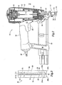
- a fastener driving tool 10 for holding and spacing an object at a predetermined distance from a substrate 1.
- Tool 10 is for driving a fastener or clip 6 for holding and spacing an object, such as wire lath 2, at a predetermined distance D from. substrate 1, wherein clip 6 includes abridge portion 7, a long prong 8 extending in a driving direction from bridge portion 7, and a short prong 9 spaced from long prong 8 and extending generally parallel to long prong 8 in the driving direction from bridge portion 7, wherein short prong 9 is substantially shorter than long prong 8.
- Novel tool 10 includes a housing 12, a driver blade 14 within housing 12 for driving clip 6 in the driving direction, a power source, such as air pressure, for driving driver blade 14, and a nosepiece 16 having a trailing end 18 coupled to housing 12, a substrate contacting end 20, a channel 22 for axially guiding driver blade 14 and fastener 6 in the driving direction toward substrate 1, a slot 24 proximate substrate contacting end 20 laterally extending into channel 22 for receiving wire lath 2, and a curved ramp 26 within channel 22, wherein a portion of ramp 26 is positioned between slot 24 and substrate contacting end 20, wherein curved ramp 26 is generally concave with respect to slot 24, ramp 26 being for interfering with the path of short prong 9 to bend short prong 9 toward long prong 8 to hold wire lath 2 between short prong 9 and bridge portion 7.
- a power source such as air pressure
- nosepiece 16 includes a stationary piece 28 having a trailing end 18a coupled to housing 12 and a substrate contacting end 20a, a movable piece 30 having a trailing end 18b pivotally coupled to housing 12 proximate trailing end 18a of stationary piece 28 and a substrate contacting end 20b, wherein movable piece 30 is pivotable between a closed position wherein the movable piece 30 is generally parallel and adjacent to stationary piece 28, see FIGS. 2 and 3, and an open position wherein movable piece 30 is angled open with respect to stationary piece 28, as shown in FIG. 4.
- Channel 22 is between stationary piece 28 and movable piece 30 when movable piece 30 is in the closed position.
- Both stationary piece 28 and movable piece 30 include a slot 24a, 24b proximate substrate contacting ends 20a, 20b of pieces 28, 30, wherein slots 24a, 24b laterally extend into channel 22 and slots 24a, 24b are aligned with one another when movable piece 30 is in the closed position so that slots 24a, 24b can receive wire lath 2 to position wire lath 2 within channel 22.
- One of pieces 28, 30 i.e. stationary piece 28 in FIG. 4) includes curved ramp 26 positioned within channel between slot 24 and substrate contacting end 20 of the one piece 28, 30.
- tool 10 is used for installing clips 6 for holding and spacing an object, preferably a wire object, at a predetermined distance D from a substrate 1.
- substrate 1 can be wood, plywood, particle board, oriented strand board (OSB board) or other wooden substrates
- tool 10 can install clip 6 to space a sheet of wire lath 2, such as hexagonal or octagonal chicken wire, from substrate 1 before applying one or more layers of plaster or stucco 4 to substrate 1.
- wire lath 2 reinforces stucco 4 to prevent it from breaking away from substrate 1 after stucco 4 has been applied.
- wire lath 2 be spaced from substrate 1 by a predetermined distance D so that wire lath 2 will be embedded generally in the middle of stucco 4, as shown in FIG. 6, to most effectively reinforce stucco 4.
- Clip 6 fastens wire lath 2 to substrate 1, as described below, so that wire lath 2 is spaced from substrate 1 by predetermined distance D.
- wire lath 2 is spaced from substrate 1 by a predetermined distance D of between about 1/8 inch (0.32 cm) and about 3/8 inch (0.96 cm), preferably between about 1 ⁇ 4 inch (0.64 cm) and about 5/16 inch (0.80 cm).
- clip 6 is a generally J shaped wire member having a bridge portion 7 with two ends 32, 34, a long prong 8 extending in the driving direction from one end 32 of bridge portion, and a short prong 9 spaced from long prong 8 at the other end 34 of bridge portion 7 extending generally parallel to long prong 8 in the driving direction, wherein the length SL of short prong 9 is substantially shorter than the length LL of long prong 8.
- bridge portion 7, long prong 8, and short prong 9 are generally linear segments that are all generally in the same plane, wherein prongs 8, 9 are generally perpendicular to bridge portion 7.
- Clip 6 should be made from a material that is strong enough to securely fasten wire lath 2 to substrate 1 and to support wire lath 2 and stucco 4 under normal conditions to prevent stucco 4 from breaking away from substrate 1.
- Clip 6 can be made from standard steel used in the construction industry, such as standard steel wire used to make staples.
- clip 6 is made from shaped 1018 carbon steel wire that has been flattened so that the wire has a width T of about 0.05 inch (1.28 mm) and a thickness W of about 1/16 inch (1.60 mm).
- the 10xx series of the Society of Automotive Engineers (SAE) includes plain carbon steels with no modification in the alleys and with 0.xx% carbon content.
- short prong length SL is between about 25% and about 45%, preferably about 35% of long prong length LL and between about 75% and about 99%, preferably about 87% of bridge portion length BL.
- bridge portion 7 can have a length BL, between about 1 ⁇ 4 inch (0.64. cm) and about 3 ⁇ 4 inch (1.92. cm), preferably between about 3/8 inch (0.96 cm) and about 5/8 inch (1.60 cm), still more preferably about 1 ⁇ 2 inch (1.28 cm)
- short prong 9 can have a length SL between about 1 ⁇ 4 inch (0.64 cm) and about 5/8 inch (1.60 cm), preferably between about 3/8 inch (0.96.cm).
- long prong 8 has a length LL of between about 1 inch (2.56 cm) and about 2 inch (5.12 cm), preferably between about 1-1/8 inch (2.88 cm) and about 1-1 ⁇ 2 inch (3.84 cm), still more preferably about 1-1 ⁇ 4 inch (3.20 cm).
- a plurality of clips 6 are arranged in a strip 36 so that a plurality of clips 6 can easily be fed to tool 10.
- Strip 36 includes a plurality of clips 6 arranged in a side-by-side array, wherein each clip 6 includes a bridge portion 7, a long prong 8 extending in a driving direction from bridge portion 7, and a short prong 9 spaced from long prong 8 and extending generally parallel to long prong 8 in the driving direction from bridge portion 7, wherein short prong 9 is substantially shorter than long prong 8.
- Clips 6 are fastened together, such as with an adhesive, in the side-by-side array so that each one of the long prongs 8 is aligned generally in a common first plane and each one of the short prongs 9 are aligned generally in a common second plane so as to form strip 36 of clips 6.
- fastener driving tool 10 of the present invention includes a housing 12 with a handle 38 depending generally from a trailing end of housing 12 for an operator to hold tool 10.
- a trigger 40 is mounted to handle 38 for actuating tool 10.
- a cylinder 42 is located within housing 12, with a piston 44 within cylinder 42.
- a driver blade 14 for driving clips 6 is coupled to piston 44 so that when piston 44 is driven in a driving direction through cylinder 42, so is driver blade 14.
- driver blade 14 is made from S-7 steel hardened to a Rockwell C hardness of between about 52 and about 56.
- a nosepiece 16 is coupled to driving end of housing 12, wherein nosepiece 16 includes a channel 22 for guiding driver blade 14 and clip 6 toward substrate 1.
- a power source such as pneumatic power, gas combustion, or explosive powder is used to drive piston 44 and driver blade 14 in the driving direction toward clip 6.
- tool 10 includes an air connection 46 for connecting to a compressed air source (not shown), which feeds into a chamber 48 in the trailing direction of piston 44. When trigger 40 is pulled by an operator, air pressure is increased in chamber 48, which drives piston 44 toward clip 6.
- Tool 10 can also include a buffer 50 generally at the driving end of cylinder 42 to protect piston 44 and tool 10 from damage due to high speed impact.
- tool 10 includes a magazine 52 for feeding a strip 36 of clips 6 into channel 22.
- Strip 36 is fed into magazine 52 of tool 10 so that a first clip is within channel 22.
- driver blade 14 When tool 10 is fired, the first clip is broken away from an adjacent second clip by driver blade 14 so that the first clip is driven toward substrate 1.
- Tool 10 can also include a follower 53 which biases strip 36 toward channel 22, so that when the first clip is driven, the follower biases the second next clip into channel 22.
- tool 10 can also include a drive probe 54 that is operationally connected to a triggering mechanism (not shown), so that tool 10 cannot be fired without drive probe 54 being pushed against substrate 1, forcing drive probe 54 in the trailing direction, enabling actuation of tool 10.
- a drive probe 54 that is operationally connected to a triggering mechanism (not shown), so that tool 10 cannot be fired without drive probe 54 being pushed against substrate 1, forcing drive probe 54 in the trailing direction, enabling actuation of tool 10.
- nosepiece 16 guides driver blade 14 toward impact with clip 6, and subsequently guides driver blade 14 and clip 6 toward substrate 1.
- nosepiece 16 includes a stationary piece 28 coupled to housing 12 and a movable piece 30 pivotably coupled to housing 12.
- a channel 22 is located between stationary piece 28 and movable piece 30, as shown in FIG. 3, for guiding driver blade 14 and clip 6.
- a slot 24a, 24b is also included near the substrate contacting end 20a, 20b for receiving wire lath 2 and positioning wire lath 2 within channel 22 so that wire lath 2 will be in the path of clip 6 so that clip 6 will hold and space wire lath 2 at the predetermined distance D from substrate 1.
- Nosepiece 16 also includes a curved ramp 26 within channel 22, a portion of which is positioned between slot 24a, 24b and substrate contacting end 20a, 20b, as shown in FIGS. 1A-1D, for bending short prong 9 to hold wire lath 2.
- Stationary piece 28 includes a trailing end 18a coupled to housing 12, a substrate contacting end 20a and a slot 24a near substrate contacting end 20a for receiving wire lath 2.
- curved ramp 26 is included on stationary piece 28, as shown in FIG. 4, with a portion of curved ramp 26 being positioned between slot 24a and substrate contacting end 20a.
- curved ramp 26 can be included on movable piece 30 without varying from the scope of the present invention.
- movable piece 30 includes a trailing end 18b pivotally coupled to housing 12, a substrate contacting end 20b and a slot 24b near substrate contacting end 20b for receiving wire lath 2.
- movable piece 30 also includes a pair of ledges 56 and shelves 58 which form a groove 60, wherein groove 60 guides clip 6 so that it remains aligned as clip 6 is driven down channel 22.
- movable piece 30 also includes a driver blade groove 62 which guides a rib 63 of driver blade 14.
- Driver blade groove 62 has a width that is narrower than the width of clip 6 so that clip 6 does not slide into driver blade groove 62.
- Nosepiece 16 can be made by steel or other means.
- nosepiece 16 is made from 8620 steel, as define by the Society of Automotive Engineers, that is investment cast made and case hardened to about 0.008 inch (0,205 mm) to about 0.012 inch (0,307 mm) with a core hardness of between about 28 Rockwell C and about 35 Rockwell C.
- clip 6 When movable piece 30 is in the closed position, clip 6 is framed within a close clearance on all its lateral sides by nosepiece 16.
- clip 6 is framed by ledges 56 to the sides, as shown in FIG. 4, by shelves 58 in the back, and by stationary piece 28 in the front, as shown in FIG. 3.
- the width GW of groove 60 between ledges 56 is only slightly larger than the width CW of clip 6 so that there is a relatively tight clearance between prongs 8, 9 of clip 6 and ledges 56 of groove 60 to guide clip 10 straight down channel 22.
- the thickness CT of channel 22 between shelves 58 on movable piece 30 and stationary piece 28 is slightly larger than the thickness T of clip 6 to prevent clip 6 from wobbling as it is driven.
- clip 6 has a width CW of about 1 ⁇ 2 inch and a thickness T of about 1/16 inch
- groove 60 has a width GW between ledges 56 of between about 17/32 inch (1.36 cm) and about 9/16 inch (1.44 cm) and a thickness CT of channel 22 of between about 5/64 inch (2 mm) and about 1/8 inch (3.2 mm) so that the total clearance on all lateral sides of clip 6 is between about 1/32 inch 0.8 mm and about 1/16 inch (1.16 mm).
- ramp 26 extends downwardly toward substrate contacting end 20 and laterally toward long prong 8 so that ramp 26 will interfere with the motion of short prong 9 as clip 6 is driven to bend short prong 9 toward long prong 8.
- Ramp 26 curves from a short prong end 64 downwardly and inwardly toward a long prong end 66 generally at a radius of curvature RR, wherein long prong end 66 is preferably generally perpendicular to short prong 9 before short prong 9 is bent by ramp 26, as shown in FIG. 1A.
- ramp 26 includes a chamfer 68 at short prong end 64 that is angled outwardly slightly from parallel to short prong 9, wherein chamfer 68 helps ensure that the distal end 70 of short prong 9 is fed into ramp 26 so that short prong 9 is bent by ramp 26.
- Ramp 26 has a height RH that is slightly larger than the length SL of short prong 9.
- Ramp 26 has a width RW that is shorter than the width CW of clip 6 and the width GW of groove 60 so that ramp 26 will interfere with the path of short prong 9, but not long prong 8 so that short prong 9 will be bent, but long prong 8 will be driven straight into substrate.
- Radius of curvature RR of ramp 26 is selected to bend short prong 9 so that wire lath 2 will be held between short prong 9 and bridge portion 7.
- Radius of curvature RR can be selected so that long prong end 66 is generally normal to short prong end 64 and so that long prong end 66 is also generally normal to prongs 8, 9, as shown in FIG. 1A, or radius of curvature RR can be selected so that long prong end 66 is angled slightly upwardly or slightly downwardly.
- ramp has a height RH of between about 7/32 inch (0.56 cm) and about 1 ⁇ 2 inch (1.28 cm), preferably about 3/8 inch (0.96 cm), a width RW of between about 3/16 inch (0.48 cm) and about 1 inch (2.56 cm), preferably about 17/32 inch (0.56 cm), and a radius of curvature RR of about 1 ⁇ 4 inch (0.74 cm).
- slots 24a, 24b are positioned in the trailing direction of long prong end 66 of ramp 26, so that when short prong 9 is bent inwardly by ramp 26, as shown in FIGS. 1A-1D, short prong 9 will bend into wire lath 2, causing wire lath 2 to be held or clamped between short prong 9 and bridge portion 7 at predetermined distance D from substrate 1.
- driver blade 14' includes a pocket 72 at the driving end of driver blade 14'.
- Pocket 72 provides a recess into which bridge portion 7 of clip 6 can be formed into so that an indentation 74 is formed in bridge portion 7 which helps to more securely hold wire lath 2 in place after short prong 9 has been bent by ramp 26.
- Pocket 72 has a width PW and height PH that compliment wire lath 2 so that indentation is formed between wire lath 2 and driver blade 14' to hold wire lath 2 in place.
- pocket 72 is generally curved with a radius of curvature that is approximately twice the radius of wire lath 2.
- pocket 72 is generally centered along the width of driver blade 14', as shown in FIG.
- pocket 72 has a width PW ofbetween about 1/8 inch (0.32 cm) and about 1 ⁇ 4 inch (0.64 cm), preferably about 0.15 inch (0.38 cm) and a height PH of between about 1/16 inch (0.16 cm) and about 3/16 inch (0.48 cm), preferably about 0.1 inch (0.26 cm).
- the method of holding and spacing wire lath 2 at the predetermined distance D from substrate 1 comprises the steps of providing clip 6 having a bridge portion 7, a long prong 8 extending in a driving direction from bridge portion 7, a short prong 9 spaced from long prong 8 and extending generally parallel to long prong 8 in the driving direction from bridge portion 7, wherein short prong 9 is substantially shorter than long prong 8, positioning the object to be held and spaced, such as wire lath 2, proximate to substrate 1, driving clip 5 so that long prong 8 is driven into substrate 1 to a predetermined depth and so that wire lath 2 is between prongs 8, 9, bending short prong 9. toward long prong 8, and holding wire lath 2 between short prong 9 and bridge portion 7 so that wire lath 2 is spaced from substrate 1 by the predetermined distance D.
- the driving step, the bending step and the holding step are all performed by tool 10 at essentially the same time. Additionally, the positioning of the wire lath 2 is accomplished by placing wire lath 2 within slot 24 in nosepiece 16 so that wire lath 2 is within channel 22 in nosepiece 16.
- Clip 6 is driven by driver blade 14, driving long prong 8 straight into substrate 1, securely fastening clip 6 to substrate 1.
- Ramp 26 interferes with the path of short prong 9, as shown in FIGS. 1A-1D, bending short prong 9 inwardly toward long prong 8 for holding or griping wire lath 2 between short prong 9 and bridge portion 7 so that wire lath 2 is held by clip 6.
- the operator can remove nosepiece 16 from engagement with clip 6 and wire lath 2 by pulling tool 10 so that bridge portion 7, short prong 9, and wire lath 2 can slide out of slot 24.
- the operator can pull tool 10 to the right in FIG. 1D, so that bridge portion 7, short prong 9, and wire lath 2 slide out of slot 24 to the left, with respect to nosepiece 16.
- the operator can pull tool 10 away from substrate 1, and insert another portion of wire lath 2 into slot 24, as shown in FIG. 1A, for holding and spacing wire lath 2 and predetermined distance D from substrate 1.
- the fastener driving tool of the present invention provides a means to quickly and securely hold and space an object, such as wire lath, at a predetermined distance from a substrate.
- the fastener driving tool provides an improvement over prior tools and methods, while still being easy for an operator to use.
Landscapes
- Engineering & Computer Science (AREA)
- Mechanical Engineering (AREA)
- Portable Nailing Machines And Staplers (AREA)
- Supply And Installment Of Electrical Components (AREA)
Applications Claiming Priority (2)
| Application Number | Priority Date | Filing Date | Title |
|---|---|---|---|
| US10/658,047 US6986448B2 (en) | 2003-09-09 | 2003-09-09 | Fastener driving tool for spacing object from substrate |
| US658047 | 2003-09-09 |
Publications (2)
| Publication Number | Publication Date |
|---|---|
| EP1514647A1 true EP1514647A1 (de) | 2005-03-16 |
| EP1514647B1 EP1514647B1 (de) | 2006-11-22 |
Family
ID=34136733
Family Applications (1)
| Application Number | Title | Priority Date | Filing Date |
|---|---|---|---|
| EP04292166A Expired - Lifetime EP1514647B1 (de) | 2003-09-09 | 2004-09-09 | Eine Nasenanordnung für ein Nagelgerät und entsprechendes Nagelgerät zur Halterung eines Gegenstandes auf Abstand von einem Substrat und Verfahren zur Halterung eines Gegenstandes |
Country Status (8)
| Country | Link |
|---|---|
| US (1) | US6986448B2 (de) |
| EP (1) | EP1514647B1 (de) |
| AT (1) | ATE345903T1 (de) |
| AU (1) | AU2004208720B2 (de) |
| CA (1) | CA2478938C (de) |
| DE (1) | DE602004003313T2 (de) |
| MX (1) | MXPA04008770A (de) |
| NZ (1) | NZ535174A (de) |
Families Citing this family (15)
| Publication number | Priority date | Publication date | Assignee | Title |
|---|---|---|---|---|
| US8590133B2 (en) | 2010-04-27 | 2013-11-26 | Toyota Motor Engineering & Manufacturing North America, Inc. | Shim placement tool |
| US9206608B2 (en) * | 2011-05-23 | 2015-12-08 | Abraham Gevorgian | Wall lath securing system |
| US9469021B2 (en) * | 2012-05-31 | 2016-10-18 | Black & Decker Inc. | Fastening tool nail channel |
| US11229995B2 (en) * | 2012-05-31 | 2022-01-25 | Black Decker Inc. | Fastening tool nail stop |
| US9486904B2 (en) * | 2012-05-31 | 2016-11-08 | Black & Decker Inc. | Fastening tool nosepiece insert |
| US9827658B2 (en) | 2012-05-31 | 2017-11-28 | Black & Decker Inc. | Power tool having latched pusher assembly |
| US9643305B2 (en) * | 2012-05-31 | 2017-05-09 | Black & Decker Inc. | Magazine assembly for fastening tool |
| US9649755B2 (en) | 2012-05-31 | 2017-05-16 | Black & Decker Inc. | Power tool having angled dry fire lockout |
| US9498871B2 (en) | 2012-05-31 | 2016-11-22 | Black & Decker Inc. | Power tool raving spring curl trip actuator |
| US10414033B2 (en) | 2012-10-04 | 2019-09-17 | Black & Decker Inc. | Power tool hall effect mode selector switch |
| US9796072B2 (en) * | 2013-08-30 | 2017-10-24 | Illinois Tool Works Inc. | Staple tool |
| US12502756B2 (en) | 2013-10-09 | 2025-12-23 | Black & Decker Inc. | High inertia driver system |
| US12544893B2 (en) | 2016-06-20 | 2026-02-10 | Black & Decker Inc. | Feed piston pressure tube |
| US11130221B2 (en) | 2019-01-31 | 2021-09-28 | Milwaukee Electric Tool Corporation | Powered fastener driver |
| US12521855B2 (en) * | 2023-04-14 | 2026-01-13 | Illinois Tool Works Inc. | Fastener driving tool having a retractable probe assembly |
Citations (6)
| Publication number | Priority date | Publication date | Assignee | Title |
|---|---|---|---|---|
| US1816387A (en) * | 1925-12-10 | 1931-07-28 | Menninger Elmore William | Furring construction |
| US2589491A (en) * | 1946-07-31 | 1952-03-18 | Charles B Goodstein | Staple setting apparatus and method |
| US3144655A (en) * | 1963-04-29 | 1964-08-18 | Samuel J Kent | Nail-driving and clinching tool |
| US3279672A (en) * | 1964-06-25 | 1966-10-18 | Powers Wire Products Company I | Fastener driving and furring tool for stucco-netting and the like |
| US3339265A (en) * | 1964-10-22 | 1967-09-05 | Powers Wire Products Co Inc | Fastener driving and reforming tool for furring stucco-netting and the like |
| EP0314831A1 (de) * | 1987-11-06 | 1989-05-10 | Joh. Friedrich Behrens AG | Befestigungsmittelstreifen und Eintreibgerät zum Eintreiben der Befestigungsmittel vom Befestigungsmittelstreifen |
Family Cites Families (15)
| Publication number | Priority date | Publication date | Assignee | Title |
|---|---|---|---|---|
| US1703560A (en) * | 1927-09-22 | 1929-02-26 | Economy Products Corp | Lath-spacing nail |
| US2589481A (en) | 1950-12-13 | 1952-03-18 | Frank G Dobbs | Foldable wallet |
| US3042924A (en) * | 1959-03-12 | 1962-07-10 | Porter Cable Machine Co | Power nailing machine |
| US3741068A (en) | 1972-01-03 | 1973-06-26 | J Andruskiewicz | Wallboard staple |
| US3915366A (en) * | 1974-07-22 | 1975-10-28 | Joseph L Mitchell | Fastener driving tool |
| US4496090A (en) * | 1982-03-10 | 1985-01-29 | Crevier Paul H | Surgical stapler |
| DE4011778C2 (de) | 1989-09-08 | 1995-06-01 | Hitachi Koki Kk | Pneumatisches Einschlagwerkzeug für Befestigungselemente |
| US5289963A (en) * | 1991-10-18 | 1994-03-01 | United States Surgical Corporation | Apparatus and method for applying surgical staples to attach an object to body tissue |
| US5484094A (en) | 1994-06-16 | 1996-01-16 | Illinois Tool Works Inc. | Workpiece-contacting probe for fastener-driving tool for fastening lath to substrate |
| US6113332A (en) * | 1996-07-08 | 2000-09-05 | Hill; Delmar J. | Multi-purpose fastening system |
| US6237827B1 (en) | 1998-11-12 | 2001-05-29 | Senco Products, Inc. | Stapler and method for the attachment of steel framing |
| US6363679B1 (en) | 1999-06-11 | 2002-04-02 | Flannery, Inc. | Fastening device |
| US6481613B1 (en) | 2000-02-16 | 2002-11-19 | Glenn J. Tebo | Fastener driving device |
| US6957756B2 (en) | 2002-04-10 | 2005-10-25 | Illinois Tool Works Inc. | Tool with nosepiece for bending fastener upon installation and fastener therefor |
| US6918222B2 (en) * | 2003-09-09 | 2005-07-19 | Illinois Tool Works Inc. | Fastener for spacing object from substrate |
-
2003
- 2003-09-09 US US10/658,047 patent/US6986448B2/en not_active Expired - Lifetime
-
2004
- 2004-08-24 CA CA002478938A patent/CA2478938C/en not_active Expired - Fee Related
- 2004-09-03 AU AU2004208720A patent/AU2004208720B2/en not_active Ceased
- 2004-09-08 NZ NZ535174A patent/NZ535174A/en not_active IP Right Cessation
- 2004-09-09 EP EP04292166A patent/EP1514647B1/de not_active Expired - Lifetime
- 2004-09-09 DE DE602004003313T patent/DE602004003313T2/de not_active Expired - Lifetime
- 2004-09-09 AT AT04292166T patent/ATE345903T1/de not_active IP Right Cessation
- 2004-09-09 MX MXPA04008770A patent/MXPA04008770A/es active IP Right Grant
Patent Citations (6)
| Publication number | Priority date | Publication date | Assignee | Title |
|---|---|---|---|---|
| US1816387A (en) * | 1925-12-10 | 1931-07-28 | Menninger Elmore William | Furring construction |
| US2589491A (en) * | 1946-07-31 | 1952-03-18 | Charles B Goodstein | Staple setting apparatus and method |
| US3144655A (en) * | 1963-04-29 | 1964-08-18 | Samuel J Kent | Nail-driving and clinching tool |
| US3279672A (en) * | 1964-06-25 | 1966-10-18 | Powers Wire Products Company I | Fastener driving and furring tool for stucco-netting and the like |
| US3339265A (en) * | 1964-10-22 | 1967-09-05 | Powers Wire Products Co Inc | Fastener driving and reforming tool for furring stucco-netting and the like |
| EP0314831A1 (de) * | 1987-11-06 | 1989-05-10 | Joh. Friedrich Behrens AG | Befestigungsmittelstreifen und Eintreibgerät zum Eintreiben der Befestigungsmittel vom Befestigungsmittelstreifen |
Also Published As
| Publication number | Publication date |
|---|---|
| NZ535174A (en) | 2005-02-25 |
| DE602004003313D1 (de) | 2007-01-04 |
| US6986448B2 (en) | 2006-01-17 |
| US20050050712A1 (en) | 2005-03-10 |
| AU2004208720B2 (en) | 2007-02-01 |
| CA2478938C (en) | 2008-06-10 |
| AU2004208720A1 (en) | 2005-03-24 |
| EP1514647B1 (de) | 2006-11-22 |
| DE602004003313T2 (de) | 2007-06-21 |
| CA2478938A1 (en) | 2005-03-09 |
| ATE345903T1 (de) | 2006-12-15 |
| MXPA04008770A (es) | 2005-05-27 |
Similar Documents
| Publication | Publication Date | Title |
|---|---|---|
| EP1514977B1 (de) | Befestiger zur beabstandeten Halterung eines Objektes von einem Substrat | |
| EP1514647B1 (de) | Eine Nasenanordnung für ein Nagelgerät und entsprechendes Nagelgerät zur Halterung eines Gegenstandes auf Abstand von einem Substrat und Verfahren zur Halterung eines Gegenstandes | |
| AU2005237853B2 (en) | Guidance system for fasteners | |
| US6957756B2 (en) | Tool with nosepiece for bending fastener upon installation and fastener therefor | |
| US7882994B2 (en) | 45 degree adjustable adapter for flooring nailer | |
| EP1074349B1 (de) | Zweiteiliges Magazin für Nagelgerät und Verfahren dafür | |
| US7011242B2 (en) | Coated staple and fastening tool for the same | |
| US20080099529A1 (en) | Fastening tool with modified driver travel path | |
| US8893943B2 (en) | Collations for fasteners of various lengths | |
| CA2437174C (en) | Stabilizing magazine follower for fastener driving tool | |
| CN1847024A (zh) | 订书机 | |
| US7617883B1 (en) | Fastening devices, method of manufacture, tool, and method of use | |
| AU716431B2 (en) | Angled chisel point brad and method therefor | |
| US5615985A (en) | Collated fastener strip | |
| US8844785B2 (en) | Powered stapler and method of operating same | |
| US20040182908A1 (en) | Power tool for metal piercing fasteners |
Legal Events
| Date | Code | Title | Description |
|---|---|---|---|
| PUAI | Public reference made under article 153(3) epc to a published international application that has entered the european phase |
Free format text: ORIGINAL CODE: 0009012 |
|
| AK | Designated contracting states |
Kind code of ref document: A1 Designated state(s): AT BE BG CH CY CZ DE DK EE ES FI FR GB GR HU IE IT LI LU MC NL PL PT RO SE SI SK TR |
|
| AX | Request for extension of the european patent |
Extension state: AL HR LT LV MK |
|
| 17P | Request for examination filed |
Effective date: 20050907 |
|
| AKX | Designation fees paid |
Designated state(s): AT BE BG CH CY CZ DE DK EE ES FI FR GB GR HU IE IT LI LU MC NL PL PT RO SE SI SK TR |
|
| GRAP | Despatch of communication of intention to grant a patent |
Free format text: ORIGINAL CODE: EPIDOSNIGR1 |
|
| GRAS | Grant fee paid |
Free format text: ORIGINAL CODE: EPIDOSNIGR3 |
|
| GRAA | (expected) grant |
Free format text: ORIGINAL CODE: 0009210 |
|
| AK | Designated contracting states |
Kind code of ref document: B1 Designated state(s): AT BE BG CH CY CZ DE DK EE ES FI FR GB GR HU IE IT LI LU MC NL PL PT RO SE SI SK TR |
|
| PG25 | Lapsed in a contracting state [announced via postgrant information from national office to epo] |
Ref country code: IT Free format text: LAPSE BECAUSE OF FAILURE TO SUBMIT A TRANSLATION OF THE DESCRIPTION OR TO PAY THE FEE WITHIN THE PRESCRIBED TIME-LIMIT;WARNING: LAPSES OF ITALIAN PATENTS WITH EFFECTIVE DATE BEFORE 2007 MAY HAVE OCCURRED AT ANY TIME BEFORE 2007. THE CORRECT EFFECTIVE DATE MAY BE DIFFERENT FROM THE ONE RECORDED. Effective date: 20061122 Ref country code: SI Free format text: LAPSE BECAUSE OF FAILURE TO SUBMIT A TRANSLATION OF THE DESCRIPTION OR TO PAY THE FEE WITHIN THE PRESCRIBED TIME-LIMIT Effective date: 20061122 Ref country code: AT Free format text: LAPSE BECAUSE OF FAILURE TO SUBMIT A TRANSLATION OF THE DESCRIPTION OR TO PAY THE FEE WITHIN THE PRESCRIBED TIME-LIMIT Effective date: 20061122 Ref country code: CH Free format text: LAPSE BECAUSE OF FAILURE TO SUBMIT A TRANSLATION OF THE DESCRIPTION OR TO PAY THE FEE WITHIN THE PRESCRIBED TIME-LIMIT Effective date: 20061122 Ref country code: RO Free format text: LAPSE BECAUSE OF FAILURE TO SUBMIT A TRANSLATION OF THE DESCRIPTION OR TO PAY THE FEE WITHIN THE PRESCRIBED TIME-LIMIT Effective date: 20061122 Ref country code: SK Free format text: LAPSE BECAUSE OF FAILURE TO SUBMIT A TRANSLATION OF THE DESCRIPTION OR TO PAY THE FEE WITHIN THE PRESCRIBED TIME-LIMIT Effective date: 20061122 Ref country code: FI Free format text: LAPSE BECAUSE OF FAILURE TO SUBMIT A TRANSLATION OF THE DESCRIPTION OR TO PAY THE FEE WITHIN THE PRESCRIBED TIME-LIMIT Effective date: 20061122 Ref country code: LI Free format text: LAPSE BECAUSE OF FAILURE TO SUBMIT A TRANSLATION OF THE DESCRIPTION OR TO PAY THE FEE WITHIN THE PRESCRIBED TIME-LIMIT Effective date: 20061122 Ref country code: PL Free format text: LAPSE BECAUSE OF FAILURE TO SUBMIT A TRANSLATION OF THE DESCRIPTION OR TO PAY THE FEE WITHIN THE PRESCRIBED TIME-LIMIT Effective date: 20061122 Ref country code: CZ Free format text: LAPSE BECAUSE OF FAILURE TO SUBMIT A TRANSLATION OF THE DESCRIPTION OR TO PAY THE FEE WITHIN THE PRESCRIBED TIME-LIMIT Effective date: 20061122 |
|
| REG | Reference to a national code |
Ref country code: GB Ref legal event code: FG4D |
|
| REG | Reference to a national code |
Ref country code: CH Ref legal event code: EP |
|
| REG | Reference to a national code |
Ref country code: IE Ref legal event code: FG4D |
|
| REF | Corresponds to: |
Ref document number: 602004003313 Country of ref document: DE Date of ref document: 20070104 Kind code of ref document: P |
|
| PG25 | Lapsed in a contracting state [announced via postgrant information from national office to epo] |
Ref country code: SE Free format text: LAPSE BECAUSE OF FAILURE TO SUBMIT A TRANSLATION OF THE DESCRIPTION OR TO PAY THE FEE WITHIN THE PRESCRIBED TIME-LIMIT Effective date: 20070222 Ref country code: BG Free format text: LAPSE BECAUSE OF FAILURE TO SUBMIT A TRANSLATION OF THE DESCRIPTION OR TO PAY THE FEE WITHIN THE PRESCRIBED TIME-LIMIT Effective date: 20070222 Ref country code: DK Free format text: LAPSE BECAUSE OF FAILURE TO SUBMIT A TRANSLATION OF THE DESCRIPTION OR TO PAY THE FEE WITHIN THE PRESCRIBED TIME-LIMIT Effective date: 20070222 |
|
| PG25 | Lapsed in a contracting state [announced via postgrant information from national office to epo] |
Ref country code: ES Free format text: LAPSE BECAUSE OF FAILURE TO SUBMIT A TRANSLATION OF THE DESCRIPTION OR TO PAY THE FEE WITHIN THE PRESCRIBED TIME-LIMIT Effective date: 20070305 |
|
| PG25 | Lapsed in a contracting state [announced via postgrant information from national office to epo] |
Ref country code: PT Free format text: LAPSE BECAUSE OF FAILURE TO SUBMIT A TRANSLATION OF THE DESCRIPTION OR TO PAY THE FEE WITHIN THE PRESCRIBED TIME-LIMIT Effective date: 20070423 |
|
| REG | Reference to a national code |
Ref country code: CH Ref legal event code: PL |
|
| ET | Fr: translation filed | ||
| PLBE | No opposition filed within time limit |
Free format text: ORIGINAL CODE: 0009261 |
|
| STAA | Information on the status of an ep patent application or granted ep patent |
Free format text: STATUS: NO OPPOSITION FILED WITHIN TIME LIMIT |
|
| 26N | No opposition filed |
Effective date: 20070823 |
|
| PG25 | Lapsed in a contracting state [announced via postgrant information from national office to epo] |
Ref country code: GR Free format text: LAPSE BECAUSE OF FAILURE TO SUBMIT A TRANSLATION OF THE DESCRIPTION OR TO PAY THE FEE WITHIN THE PRESCRIBED TIME-LIMIT Effective date: 20070223 Ref country code: MC Free format text: LAPSE BECAUSE OF NON-PAYMENT OF DUE FEES Effective date: 20070930 |
|
| PG25 | Lapsed in a contracting state [announced via postgrant information from national office to epo] |
Ref country code: IE Free format text: LAPSE BECAUSE OF NON-PAYMENT OF DUE FEES Effective date: 20070910 |
|
| PG25 | Lapsed in a contracting state [announced via postgrant information from national office to epo] |
Ref country code: EE Free format text: LAPSE BECAUSE OF FAILURE TO SUBMIT A TRANSLATION OF THE DESCRIPTION OR TO PAY THE FEE WITHIN THE PRESCRIBED TIME-LIMIT Effective date: 20061122 |
|
| PG25 | Lapsed in a contracting state [announced via postgrant information from national office to epo] |
Ref country code: LU Free format text: LAPSE BECAUSE OF NON-PAYMENT OF DUE FEES Effective date: 20070909 Ref country code: CY Free format text: LAPSE BECAUSE OF FAILURE TO SUBMIT A TRANSLATION OF THE DESCRIPTION OR TO PAY THE FEE WITHIN THE PRESCRIBED TIME-LIMIT Effective date: 20061122 |
|
| PG25 | Lapsed in a contracting state [announced via postgrant information from national office to epo] |
Ref country code: HU Free format text: LAPSE BECAUSE OF FAILURE TO SUBMIT A TRANSLATION OF THE DESCRIPTION OR TO PAY THE FEE WITHIN THE PRESCRIBED TIME-LIMIT Effective date: 20070523 Ref country code: TR Free format text: LAPSE BECAUSE OF FAILURE TO SUBMIT A TRANSLATION OF THE DESCRIPTION OR TO PAY THE FEE WITHIN THE PRESCRIBED TIME-LIMIT Effective date: 20061122 |
|
| PGFP | Annual fee paid to national office [announced via postgrant information from national office to epo] |
Ref country code: NL Payment date: 20090924 Year of fee payment: 6 |
|
| PGFP | Annual fee paid to national office [announced via postgrant information from national office to epo] |
Ref country code: BE Payment date: 20091026 Year of fee payment: 6 |
|
| BERE | Be: lapsed |
Owner name: ILLINOIS TOOL WORKS INC. Effective date: 20100930 |
|
| REG | Reference to a national code |
Ref country code: NL Ref legal event code: V1 Effective date: 20110401 |
|
| PG25 | Lapsed in a contracting state [announced via postgrant information from national office to epo] |
Ref country code: BE Free format text: LAPSE BECAUSE OF NON-PAYMENT OF DUE FEES Effective date: 20100930 |
|
| PG25 | Lapsed in a contracting state [announced via postgrant information from national office to epo] |
Ref country code: NL Free format text: LAPSE BECAUSE OF NON-PAYMENT OF DUE FEES Effective date: 20110401 |
|
| REG | Reference to a national code |
Ref country code: FR Ref legal event code: PLFP Year of fee payment: 12 |
|
| REG | Reference to a national code |
Ref country code: FR Ref legal event code: PLFP Year of fee payment: 13 |
|
| REG | Reference to a national code |
Ref country code: FR Ref legal event code: PLFP Year of fee payment: 14 |
|
| REG | Reference to a national code |
Ref country code: FR Ref legal event code: PLFP Year of fee payment: 15 |
|
| PGFP | Annual fee paid to national office [announced via postgrant information from national office to epo] |
Ref country code: FR Payment date: 20190925 Year of fee payment: 16 |
|
| PGFP | Annual fee paid to national office [announced via postgrant information from national office to epo] |
Ref country code: GB Payment date: 20190927 Year of fee payment: 16 |
|
| PGFP | Annual fee paid to national office [announced via postgrant information from national office to epo] |
Ref country code: DE Payment date: 20190927 Year of fee payment: 16 |
|
| REG | Reference to a national code |
Ref country code: DE Ref legal event code: R119 Ref document number: 602004003313 Country of ref document: DE |
|
| GBPC | Gb: european patent ceased through non-payment of renewal fee |
Effective date: 20200909 |
|
| PG25 | Lapsed in a contracting state [announced via postgrant information from national office to epo] |
Ref country code: FR Free format text: LAPSE BECAUSE OF NON-PAYMENT OF DUE FEES Effective date: 20200930 Ref country code: DE Free format text: LAPSE BECAUSE OF NON-PAYMENT OF DUE FEES Effective date: 20210401 |
|
| PG25 | Lapsed in a contracting state [announced via postgrant information from national office to epo] |
Ref country code: GB Free format text: LAPSE BECAUSE OF NON-PAYMENT OF DUE FEES Effective date: 20200909 |