EP1514568A1 - Einwegspritze - Google Patents
Einwegspritze Download PDFInfo
- Publication number
- EP1514568A1 EP1514568A1 EP03254674A EP03254674A EP1514568A1 EP 1514568 A1 EP1514568 A1 EP 1514568A1 EP 03254674 A EP03254674 A EP 03254674A EP 03254674 A EP03254674 A EP 03254674A EP 1514568 A1 EP1514568 A1 EP 1514568A1
- Authority
- EP
- European Patent Office
- Prior art keywords
- surrounding
- disposed
- segment
- proximate
- disposable syringe
- Prior art date
- Legal status (The legal status is an assumption and is not a legal conclusion. Google has not performed a legal analysis and makes no representation as to the accuracy of the status listed.)
- Withdrawn
Links
Images


Classifications
-
- A—HUMAN NECESSITIES
- A61—MEDICAL OR VETERINARY SCIENCE; HYGIENE
- A61M—DEVICES FOR INTRODUCING MEDIA INTO, OR ONTO, THE BODY; DEVICES FOR TRANSDUCING BODY MEDIA OR FOR TAKING MEDIA FROM THE BODY; DEVICES FOR PRODUCING OR ENDING SLEEP OR STUPOR
- A61M5/00—Devices for bringing media into the body in a subcutaneous, intra-vascular or intramuscular way; Accessories therefor, e.g. filling or cleaning devices, arm-rests
- A61M5/178—Syringes
- A61M5/31—Details
- A61M5/32—Needles; Details of needles pertaining to their connection with syringe or hub; Accessories for bringing the needle into, or holding the needle on, the body; Devices for protection of needles
- A61M5/3205—Apparatus for removing or disposing of used needles or syringes, e.g. containers; Means for protection against accidental injuries from used needles
- A61M5/321—Means for protection against accidental injuries by used needles
- A61M5/322—Retractable needles, i.e. disconnected from and withdrawn into the syringe barrel by the piston
- A61M5/3234—Fully automatic needle retraction, i.e. in which triggering of the needle does not require a deliberate action by the user
-
- A—HUMAN NECESSITIES
- A61—MEDICAL OR VETERINARY SCIENCE; HYGIENE
- A61M—DEVICES FOR INTRODUCING MEDIA INTO, OR ONTO, THE BODY; DEVICES FOR TRANSDUCING BODY MEDIA OR FOR TAKING MEDIA FROM THE BODY; DEVICES FOR PRODUCING OR ENDING SLEEP OR STUPOR
- A61M5/00—Devices for bringing media into the body in a subcutaneous, intra-vascular or intramuscular way; Accessories therefor, e.g. filling or cleaning devices, arm-rests
- A61M5/178—Syringes
- A61M5/31—Details
- A61M5/32—Needles; Details of needles pertaining to their connection with syringe or hub; Accessories for bringing the needle into, or holding the needle on, the body; Devices for protection of needles
- A61M5/3205—Apparatus for removing or disposing of used needles or syringes, e.g. containers; Means for protection against accidental injuries from used needles
- A61M5/321—Means for protection against accidental injuries by used needles
- A61M5/322—Retractable needles, i.e. disconnected from and withdrawn into the syringe barrel by the piston
- A61M5/3221—Constructional features thereof, e.g. to improve manipulation or functioning
- A61M2005/3231—Proximal end of needle captured or embedded inside piston head, e.g. by friction or hooks
-
- A—HUMAN NECESSITIES
- A61—MEDICAL OR VETERINARY SCIENCE; HYGIENE
- A61M—DEVICES FOR INTRODUCING MEDIA INTO, OR ONTO, THE BODY; DEVICES FOR TRANSDUCING BODY MEDIA OR FOR TAKING MEDIA FROM THE BODY; DEVICES FOR PRODUCING OR ENDING SLEEP OR STUPOR
- A61M5/00—Devices for bringing media into the body in a subcutaneous, intra-vascular or intramuscular way; Accessories therefor, e.g. filling or cleaning devices, arm-rests
- A61M5/178—Syringes
- A61M5/31—Details
- A61M5/32—Needles; Details of needles pertaining to their connection with syringe or hub; Accessories for bringing the needle into, or holding the needle on, the body; Devices for protection of needles
- A61M5/3205—Apparatus for removing or disposing of used needles or syringes, e.g. containers; Means for protection against accidental injuries from used needles
- A61M5/321—Means for protection against accidental injuries by used needles
- A61M5/322—Retractable needles, i.e. disconnected from and withdrawn into the syringe barrel by the piston
- A61M5/3234—Fully automatic needle retraction, i.e. in which triggering of the needle does not require a deliberate action by the user
- A61M2005/3239—Fully automatic needle retraction, i.e. in which triggering of the needle does not require a deliberate action by the user triggered by dislodgement of outer part anchoring the needle portion to the inside of the syringe barrel wall, e.g. a ring-shaped portion
-
- A—HUMAN NECESSITIES
- A61—MEDICAL OR VETERINARY SCIENCE; HYGIENE
- A61M—DEVICES FOR INTRODUCING MEDIA INTO, OR ONTO, THE BODY; DEVICES FOR TRANSDUCING BODY MEDIA OR FOR TAKING MEDIA FROM THE BODY; DEVICES FOR PRODUCING OR ENDING SLEEP OR STUPOR
- A61M5/00—Devices for bringing media into the body in a subcutaneous, intra-vascular or intramuscular way; Accessories therefor, e.g. filling or cleaning devices, arm-rests
- A61M5/178—Syringes
- A61M5/31—Details
- A61M5/32—Needles; Details of needles pertaining to their connection with syringe or hub; Accessories for bringing the needle into, or holding the needle on, the body; Devices for protection of needles
- A61M5/3205—Apparatus for removing or disposing of used needles or syringes, e.g. containers; Means for protection against accidental injuries from used needles
- A61M5/321—Means for protection against accidental injuries by used needles
- A61M5/322—Retractable needles, i.e. disconnected from and withdrawn into the syringe barrel by the piston
- A61M5/3234—Fully automatic needle retraction, i.e. in which triggering of the needle does not require a deliberate action by the user
- A61M2005/3241—Needle retraction energy is accumulated inside of a hollow plunger rod
-
- A—HUMAN NECESSITIES
- A61—MEDICAL OR VETERINARY SCIENCE; HYGIENE
- A61M—DEVICES FOR INTRODUCING MEDIA INTO, OR ONTO, THE BODY; DEVICES FOR TRANSDUCING BODY MEDIA OR FOR TAKING MEDIA FROM THE BODY; DEVICES FOR PRODUCING OR ENDING SLEEP OR STUPOR
- A61M25/00—Catheters; Hollow probes
- A61M25/01—Introducing, guiding, advancing, emplacing or holding catheters
- A61M25/06—Body-piercing guide needles or the like
- A61M25/0612—Devices for protecting the needle; Devices to help insertion of the needle, e.g. wings or holders
- A61M25/0631—Devices for protecting the needle; Devices to help insertion of the needle, e.g. wings or holders having means for fully covering the needle after its withdrawal, e.g. needle being withdrawn inside the handle or a cover being advanced over the needle
-
- A—HUMAN NECESSITIES
- A61—MEDICAL OR VETERINARY SCIENCE; HYGIENE
- A61M—DEVICES FOR INTRODUCING MEDIA INTO, OR ONTO, THE BODY; DEVICES FOR TRANSDUCING BODY MEDIA OR FOR TAKING MEDIA FROM THE BODY; DEVICES FOR PRODUCING OR ENDING SLEEP OR STUPOR
- A61M5/00—Devices for bringing media into the body in a subcutaneous, intra-vascular or intramuscular way; Accessories therefor, e.g. filling or cleaning devices, arm-rests
- A61M5/178—Syringes
- A61M5/31—Details
- A61M5/32—Needles; Details of needles pertaining to their connection with syringe or hub; Accessories for bringing the needle into, or holding the needle on, the body; Devices for protection of needles
- A61M5/3205—Apparatus for removing or disposing of used needles or syringes, e.g. containers; Means for protection against accidental injuries from used needles
- A61M5/321—Means for protection against accidental injuries by used needles
- A61M5/322—Retractable needles, i.e. disconnected from and withdrawn into the syringe barrel by the piston
- A61M5/3232—Semi-automatic needle retraction, i.e. in which triggering of the needle retraction requires a deliberate action by the user, e.g. manual release of spring-biased retraction means
Definitions
- This invention relates to a disposable syringe, more particularly to a disposable syringe which enables a needle cannula to be retracted into a plunger body.
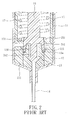
- U.S. patent No. 5,211, 62 8 discloses a syringe with an automatic retracting needle, which includes a barrel 11 with a chamber, a flexible lock member 12 fixed in the chamber adjacent to a lower end 111 thereof, a flexible needle seat 13 positioned in the chamber adjacent to the lower end 111 and formed with an opening 131, a needle cannula 14 fastened to the needle seat 13 in the opening 131 and extending through an orifice 112 in the lower end 111, a plunger 15 slidable in the chamber along an axis (X), a shaft 16 disposed in the plunger 15 and having an integral annular lower foot part 161 which is press-fitted against an upwardly extending lip 151 of the plunger 15, and a spring 17 surrounding the shaft 16 and having one end 172 which abuts against an upper end 163 of the shaft 16 and the other end 171 which is retained in a compressed state by engagement of the lip 151 with the lower foot part 161.
- the shaft 16 further includes a lower protrusion 162 shaped to mate with the opening 131.
- the lower protrusion 162 can be inserted into the opening 131, and the lower foot part 161 spreads the lip 121 outwardly so that the lip 121 is bent to disengage from the shoulder 134.
- the residual force of the lip 121 against the lower foot part 161 causes a slight inward bend of the lower foot part 161 and momentarily causes the lower foot part 161 to lose contact with the lip 151.
- the compressive force of the spring 17 then urges the upper end 163 of the shaft 16 upwardly. Due to the mating fit of the lower protrusion 162 with the opening 131, the upward movement is also transferred to the needle seat 13 and the needle cannula 14 which are urged upwardly into the plunger 15.
- the engagement of the lower foot part 161 with the lip 151 cannot be very tight.
- a loose engagement may result in an undesired release of the compressive force of the spring 17.
- some medicine may enter the plunger 15 from a clearance between the lower foot part 161 and the lip 151.
- the lower foot part 161 which has a conical shape, may interfere with the retraction of the shaft 16 into the plunger 15.
- the object of the present invention is to provide a disposable syringe which can be operated easily and smoothly to retract a used needle into a plunger body.
- the disposable syringe includes a barrel which has an inner surrounding barrel wall surface surrounding an axis and confining a passage.
- the passage has open lower and upper ends opposite to each other in a longitudinal direction parallel to the axis.
- the inner surrounding barrel wall surface includes a larger-diameter segment and a smaller-diameter segment which are disposed proximate to the open lower and upper ends, respectively, to form a surrounding shoulder portion therebetween.
- the smaller-diameter segment includes a front surrounding region and a rear surrounding region which is proximate to the surrounding shoulder portion.
- the larger-diameter segment includes proximate and distal surrounding regions respectively disposed proximate to and distal from the surrounding shoulder portion.
- a tubular needle seat includes a hub portion which is disposed to fix a needle cannula therein, and which has a surrounding front end wall extending radially relative to the axis, a surrounding gripped portion extending from the hub portion, and an anchoring portion extending from the surrounding gripped portion.
- a grip member is disposed to bring the surrounding gripped portion into engagement with one of the rear surrounding region and the proximate surrounding region.
- the grip member can provide a resisting force that holds the surrounding gripped portion in position so as to prevent movement of the surrounding gripped portion relative to a respective one of the rear surrounding region and the proximate surrounding region during a piercing action of the needle cannula for a hypodermic injection, and that permits disengagement of the surrounding gripped portion from the respective one of the rear surrounding region and the proximate surrounding region so as to enable a subsequent movement of the tubular needle seat relative to the inner surrounding barrel wall surface when the surrounding gripped portion is subjected to a first external force.
- a plunger in a position of use, is disposed to be movable in the larger-diameter segment, and includes a plunger body and a coupling rod.
- the plunger body includes a top end wall movable towards the anchoring portion, a bottom end wall opposite to the top end wall, and a tubular intermediate wall interposed between the top and bottom end walls and confining an accommodation chamber.
- the top end wall has an inner peripheral edge portion defining an access opening therein, which is communicated with the accommodation chamber.
- the coupling rod includes an upper coupling end which is inserted in the access opening, and which has a central anchored area that is engageable with the anchoring portion by a holding force such that engagement of the central anchored area with the anchoring portion is not disrupted during the disengagement of the surrounding gripped portion from the respective one of the rear surrounding region and the proximate surrounding region.
- the upper coupling end further has a surrounding abutment area which surrounds the central anchored area, and which is in frictional engagement with the inner peripheral edge portion.
- the coupling rod when the upper coupling end is depressed towards the bottom end wall by virtue of movement of the tubular needle seat relative to the upper coupling end, the coupling rod is disengaged from the inner peripheral edge portion so as to enable the coupling rod to be forced from the position of use to a retracted position where the coupling rod is disposed closer to the bottom end wall.
- the coupling rod further includes a shank portion extending from the upper coupling end towards the bottom end wall and terminating at a thrust end.
- a biasing member is disposed between the shank portion and the tubular intermediate wall to bias the coupling rod towards the retracted position.
- a retaining member is disposed to retain the thrust end in the position of use against biasing action of the biasing member.
- a triggering member is disposed to prevent the retaining member from retaining the thrust end in response to a second external force, thereby permitting the coupling rod to be biased towards the retracted position.
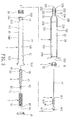
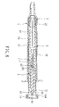
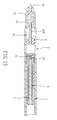
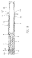
- the first preferred embodiment of a disposable syringe according to the present invention is shown to comprise a barrel 2, a needle assembly 4 including a needle cannula 42, a tubular needle seat 41 and a tip protector 43, a grip member 3, a plunger, a biasing member 7, a retaining member 8 and a triggering member.
- the barrel 2 has an inner surrounding barrel wall surface 230 which surrounds an axis (X) and which confines a passage.
- the passage has an open lower end 232 and an open upper end 231 which are disposed opposite to each other in a longitudinal direction parallel to the axis (X).
- the inner surrounding barrel wall surface 230 includes a larger-diameter segment 22 and a smaller-diameter segment 21 which confine rear and front passageways, respectively, and which are disposed proximate to the open lower end 232 and the open upper end 231, respectively, to form a surrounding shoulder portion 26 therebetween.
- the smaller-diameter segment 21 includes a front surrounding region 233, a rear surrounding region 234 which is proximate to the surrounding shoulder portion 26, and a shoulder 235 which is disposed between the front and rear surrounding regions 233, 234.
- the larger-diameter segment 22 includes proximate and distal surrounding regions 221,222 which are opposite to each other in the longitudinal direction and which are respectively proximate to and distal from the surrounding shoulder portion 26.
- the proximate and distal surrounding regions 221, 222 are formed with retaining protrusions 238,239, respectively.
- the barrel 2 further has an outer surrounding barrel wall surface 29 which surrounds the axis (X), and which includes front and rear outer surrounding segments 291,292 that are disposed opposite to the smaller-diameter segment 21 and the larger-diameter segment 22 in directions radial to the axis (X), respectively, and a transition surrounding segment 293 which is interposed between the front and rear outer surrounding segments 291,292, and which diverges gradually from the front outer surrounding segment 291 to the rear outer surrounding segment 292.
- a rib portion 236 is disposed on the front outer surrounding segment 291, and extends in the longitudinal direction to the transition surrounding segment 293.
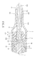
- the needle seat 41 includes a hub portion 416 which is disposed to fix the needle cannula 42 therein, and which has a surrounding front end wall 411 extending radially relative to the axis (X), a surrounding gripped portion 417 which extends from the hub portion 416 in the longitudinal direction and away from the surrounding front end wall 411, and an anchoring portion 412 which extends from the surrounding gripped portion 417 in the longitudinal direction and away from the hub portion 416.
- the surrounding front end wall 411 is disposed to abut against the shoulder 235 so as to block forward movement of the needle seat 41.
- the needle cannula 42 extends through the open upper end 231.
- the tip protector 43 is sleeved frictionally on the rib portion 236 for shielding the needle cannula 42. Note that the extension of the rib portion 236 onto the transition surrounding segment 293 ensures the firm engagement between the tip protector 43 and the rib portion 236.
- a grip member 3 includes an outer grip wall surface 32 which engages retainingly the retaining protrusion 238 with a first frictional force and which is in water-tight engagement with the proximate surrounding region 221, and an inner grip wall surface 31 which is opposite to the outer grip wall surface 32 in radial directions relative to the axis (X) and which engages retainingly the surrounding gripped portion 417 of the needle seat 41 with a second frictional force that, together with the first frictional force, provides a resisting force.
- the resisting force i.e.
- the first and second frictional forces can hold the surrounding gripped portion 417 in position so as to prevent movement of the surrounding gripped portion 417 relative to the proximate surrounding region 221 during a piercing action of the needle cannula 42 for a hypodermic injection, and can permit disengagement of the surrounding gripped portion 417 from the proximate surrounding region 221 to enable a subsequent movement of the needle seat 41 relative to the inner surrounding barrel wall surface 230 when the surrounding gripped portion 417 is subjected to a first external force.
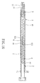
- the plunger includes a plunger body 5 and a coupling rod 6, and is disposed to be movable in the larger-diameter segment 22 in a position of use.
- the plunger body 5 includes a top end wall 543 which is disposed to be movable towards the anchoring portion 412, a bottom end wall 544 which is opposite to the top end wall 543 in the longitudinal direction, and which extends outwardly of the open lower end 232 so as to be manually operable, and a tubular intermediate wall 54 which is interposed between the top and bottom end walls 543,544, and which confines an accommodation chamber 51.
- the accommodation chamber 51 includes front and rear chamber regions 511,512 which are respectively proximate to the top and bottom end walls 543,544, and the rear chamber region 512 has an inner diameter larger than that of the front chamber region 511.
- the top end wall 543 has an inner peripheral edge portion 545 which surrounds the axis (X), and which defines an access opening 53 therein to be communicated with the accommodation chamber 51.
- a deformable surrounding ring 56 is sleeved retainingly on the top end wall 543.
- the tubular intermediate wall 54 has outer and inner tubular wall surfaces 546,541 opposite to each other in radial directions relative to the axis (X).
- An end cap 55 is disposed to cover the bottom end wall 544.
- the coupling rod 6 includes an upper coupling end 61 and a shank portion 67.
- the upper coupling end 61 is inserted in the access opening 53, and has a central anchored area 63 which has an engaging recess that confronts the anchoring portion 412 and that extends in the longitudinal direction so as to be engageable with the anchoring portion 412.
- the engaging recess and the anchoring portion 412 are shaped to mate with each other with a holding force such that the engagement of the central anchored area 63 with the anchoring portion 412 is not disrupted during the disengagement of the surrounding gripped portion 417 from the proximate surrounding region 221.
- the upper coupling end 61 further has a surrounding abutment area 66 which surrounds the central anchored area 63, and which is disposed to be in frictional engagement with the inner peripheral edge portion 545.
- a surrounding abutment area 66 which surrounds the central anchored area 63, and which is disposed to be in frictional engagement with the inner peripheral edge portion 545.
- the retaining member 8 includes a spiral retaining groove 81 which is formed in the inner tubular wall surface 541 at the front chamber region 511, which extends radially towards the outer tubular wall surface 546, and which is displaced from the top end wall 543, and a positioning groove 82 which is formed in the thrust end 62.
- the biasing member 7 is a coiled spring 7 that surrounds the shank portion 67.
- the coiled spring 7 has an upper end 71 which abuts against a step portion 542 of the top end wall 543, and a lower end 72 opposite to the upper end 71 and having a diameter substantially larger than that of the upper end 71.
- the lower end 72 is inserted into and is retained in the retaining groove 81 against a biasing action of the coiled spring 7 so as to retain the thrust end 62 in the position of use against the biasing action.
- the triggering member includes an actuated portion which is formed integrally with the coiled spring 7.
- the actuated portion has a pushed end 83 which is inserted into the positioning groove 82 to be moved with the thrust end 62, and a pulling end 89 which is disposed to pull the lower end 72 out of the retaining groove 81 once the pushed end 83 is moved downwardly with the thrust end 62 when the upper coupling end 61 is depressed to be disengaged from the inner peripheral edge 545 in response to a second external force, thereby enabling the coupling rod 6 to be forced by virtue of the biasing action of the coiled spring 7 to move to the retracted position.
- the plunger body 5 is pressed forwardly to push the surrounding ring 56 against the grip member 3 to complete an injection course.
- a part of the anchoring portion 412 is inserted into the engaging recess of the central anchored area 63, as shown in Fig. 5.
- a pushing force i.e. the aforesaid first external force, which is greater than the resisting force
- the top end wall 543 and the surrounding ring 56 are moved to push the grip member 3 towards the surrounding shoulder portion 26 relative to the surrounding grip portion 417 due to the abutment of the surrounding front end wall 411 against the shoulder 235.
- the surrounding grip portion 417 is then disengaged from the inner grip wall surface 31 and from the proximate surrounding region 221, thereby enabling the anchoring portion 412 to engage the engaging recess of the central anchored area 63.
- the needle seat 41 and the needle cannula 42 can be retracted into the accommodation chamber 51, and can be retained in the accommodation chamber 51 by the end cap 55.
- the dimension of the rear chamber segment 512 is larger than that of the front chamber segment 511, the way for the biasing member 7 is cleared when the biasing member 7 biases the coupling rod 6 towards the retracting position.
- the plunger body 5 may be pulled rearward after the engagement of the central anchored area 63 with the anchoring portion 412 so that the needle seat 41 and the needle cannula 42 can be retracted into the passage of the barrel 2 without using the biasing action of the coiled spring 7.
- the second preferred embodiment of a disposable syringe according to this invention is shown to be similar to the first preferred embodiment in construction.
- the differences reside in that the thrust end 62 of the coupling rod 6 has an enlarged end edge 84 which, in cooperation with the shank portion 67, forms an abutment shoulder 621 for engaging the lower end 72 of the coiled spring 7.
- the retaining member 8 further has a spirally surrounding protrusion 85 which is formed on and which extends radially from the enlarged end edge 84 so as to releasably engage the retaining groove 81 in the inner tubular wall surface 541 of the plunger body 5.
- the anchoring portion 412 when the anchoring portion 412 is pressed to move the upper coupling end 61 relative to the inner peripheral edge portion 545 by virtue of the second external force, the surrounding protrusion 85 is moved to disengage from the retaining groove 81 so as to permit retraction of the coupling rod 6, the needle seat 41 and the needle cannula 42 into the accommodation chamber 51.
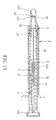
- the third preferred embodiment of a disposable syringe according to this invention is shown to be similar to the first preferred embodiment in construction, and further includes a sealing member 44 which is in air-tight engagement with the rear surrounding region 234 so as to cooperate with the grip member 3 to confine a compressible chamber 443 in the proximate surrounding region 221.
- the compressible chamber 443 is filled with a fluid.
- the sealing member 44 includes an elastomeric plate 441 and an elastomeric ring 442 which abut against each other.
- the hub portion 416 of the needle seat 41 has a through hole 413 which is formed therethrough and which is in fluid communication with the compressible chamber 443 such that when the grip member 3 is moved towards the surrounding shoulder portion 26, the fluid is forced to flow into the through hole 413 to assist in depression of the upper coupling end 61 of the coupling rod 6, as well as the needle seat 41 and the needle cannula 42, towards the bottom end wall 544, thereby speeding up the movement of the coupling rod 6 to the retracted position.
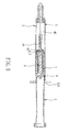
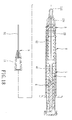
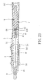
- the fourth preferred embodiment of a disposable syringe according to this invention is adapted for injecting medication of a very small volume, such as 1 ml.
- the barrel 2, the grip member 3, the needle seat 41, the plunger body 5, the coupling rod 6, the biasing member 7 and the retaining member 8 are comparatively smaller in size.
- an embossed pin 65 extends from the pushed end 83 forwardly, projects forwardly of the central anchored area 63 of the coupling rod 6, and is formed with screw threads thereon.
- the embossed pin 65 extends toward the anchoring portion 412 of the needle seat 41 for insertion thereinto and for retention therein, thereby providing the holding force.
- the embossed pin 65 is also formed on and extends from the central anchored area 63 of the coupling rod 6.
- a needle mount 45 is provided to sleeve on and to secure the needle cannula 42 and the hub portion 416 of the needle seat 41. An assembly of the needle mount 45, the needle cannula 42 and the needle seat 41 is inserted into the barrel 2.
- mounting of the needle cannula 42 and the needle seat 41 to the barrel 2 can be conducted easily, and the smaller-diameter segment 21 of the barrel 2 can have a relatively large diameter so as to facilitate fabrication.
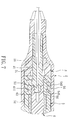
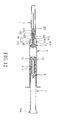
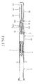
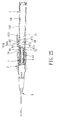
- the fifth preferred embodiment of a disposable syringe according to this invention is shown to be similar to the first preferred embodiment in construction, and further includes an intravenous catheter device 9 which includes a catheter hub 91 and a tubular catheter 92.
- the catheter hub 91 defines a duct therein, and includes a sleeve portion that is sleeved on the outer surrounding barrel wall surface 29 of the barrel 2 adjacent to the open upper end 231, and a tip portion opposite to the sleeve portion along the axis.
- the tubular catheter 92 has a proximate segment which is disposed in the tip portion of the catheter hub 91 and which extends along the axis to communicate fluidly with the duct, and a distal segment that extends from the proximate segment along the axis to project outwardly of the tip portion.
- the needle cannula 42 extends through the tubular catheter 92 to terminate at a tip end 421 that projects outwardly of the distal segment of the tubular catheter 92.
- the user can pull the plunger body 5 slightly rearward to draw blood so as to confirm correct insertion of the tubular catheter 92 into the patient's vein.
- the needle seat 41 and the needle cannula 42 are retracted into the plunger body 5 in the same manner as described above.
- the sixth preferred embodiment of a disposable syringe according to this invention is shown to be similar to the fifth preferred embodiment in construction, and further includes a first male screw thread segment 547 and a first female screw thread segment 24 which are respectively disposed on the outer tubular wall surface 546 of the plunger body 5 and the distal surrounding region 222 of larger-diameter segment 22 of the barrel 2.
- first male screw thread segment 547 is in a screw-in engagement with the first female screw thread segment 24 to provide the second external force
- the plunger body 5 can be moved more easily to push the grip member 3 to the surrounding shoulder portion 26.
- the seventh preferred embodiment of a disposable syringe according to this invention is shown to be similar to the sixth preferred embodiment in construction.
- the grip member includes a second female screw thread segment 25 which is disposed on the rear surrounding region 234 of the smaller-diameter segment 21 of the barrel 2, and a second male screw thread segment 415 which is disposed on the surrounding gripped portion 417 of the needle seat 41.
- the second male screw thread segment 415 is in a threaded engagement with the second female screw thread segment 25 such that the resisting force is provided between the surrounding gripped portion 417 and the rear surrounding region 234, and such that screw-out movement of the second male screw thread segment 415 relative to the second female screw thread segment 25 results in disappearance of the resisting force to permit disengagement of the surrounding gripped portion 417 from the rear surrounding region 234.
- the central anchored area 63 has a third female screw thread segment 68 which is disposed in the engaging recess thereof.
- the anchoring portion 412 has a third male screw thread segment 414. The anchoring portion 412 is brought into engagement with the central anchored area 63 by virtue of rotation of the third male screw thread segment 414 and the third female screw thread segment 68 relative to each other, thereby providing the holding force.
- the eighth preferred embodiment of a disposable syringe according to this invention is shown to be similar to the seventh preferred embodiment in construction.
- the differences reside in that the thrust end 62 of the coupling rod 6 has an enlarged end edge 84 which, in cooperation with the shank portion 67, forms an abutment shoulder 621 for engaging the lower end 72 of the coiled spring 7.
- the outer tubular wall surface 546 of the tubular intermediate wall 54 of the plunger body 5 has an access hole 86 which extends radially through the inner tubular wall surface 541.
- the retaining member 8 has a locking pin 872 which is received in the access hole 86 and which is movable radially between a locking position (see Fig. 25), where the locking pin 872 extends into the accommodation chamber 51 to abut the enlarged end edge 84 against the biasing action of the coiled spring 7, and a releasing position (see Fig. 26), where the locking pin 872 is retracted to release the enlarged end edge 84 so that the coupling rod 6 is forced by virtue of the biasing action of the coiled spring 7 to move to the retracted position.
- the triggering member is formed as a lever 87, and is mounted pivotally on the outer tubular wall surface 546 at a fulcrum point 871 by means of a C-shaped clip 88 which is sleeved on the outer tubular wall surface 546 and which has an end 881 passing through the fulcrum point 871.
- the lever 87 includes a weight end 874 which is formed integrally with the locking pin 872, and a power end 873 which is disposed at the opposite side of the weight end 874 relative to the fulcrum point 871 so as to be actuated to move the locking pin 872 to the releasing position.
- the tubular intermediate wall 54 of the plunger body 5 has two access holes 86
- the retaining member 8 has two locking pins 872
- the triggering member has two levers 87 which are mounted pivotally on the tubular intermediate wall 54 by means of a C-shaped clip 88. Pressing of the power ends 873 of the levers 87 can result in retraction of the locking pins 872 to permit retracting movement of the coupling rod 6 by virtue of the biasing action of the coiled spring 7.
- the disposable syringe of this invention has the following advantages:
Landscapes
- Health & Medical Sciences (AREA)
- Engineering & Computer Science (AREA)
- Heart & Thoracic Surgery (AREA)
- Vascular Medicine (AREA)
- Anesthesiology (AREA)
- Biomedical Technology (AREA)
- Environmental & Geological Engineering (AREA)
- Hematology (AREA)
- Life Sciences & Earth Sciences (AREA)
- Animal Behavior & Ethology (AREA)
- General Health & Medical Sciences (AREA)
- Public Health (AREA)
- Veterinary Medicine (AREA)
- Infusion, Injection, And Reservoir Apparatuses (AREA)
Priority Applications (1)
| Application Number | Priority Date | Filing Date | Title |
|---|---|---|---|
| EP03254674A EP1514568A1 (de) | 2003-07-25 | 2003-07-25 | Einwegspritze |
Applications Claiming Priority (1)
| Application Number | Priority Date | Filing Date | Title |
|---|---|---|---|
| EP03254674A EP1514568A1 (de) | 2003-07-25 | 2003-07-25 | Einwegspritze |
Publications (1)
| Publication Number | Publication Date |
|---|---|
| EP1514568A1 true EP1514568A1 (de) | 2005-03-16 |
Family
ID=34130332
Family Applications (1)
| Application Number | Title | Priority Date | Filing Date |
|---|---|---|---|
| EP03254674A Withdrawn EP1514568A1 (de) | 2003-07-25 | 2003-07-25 | Einwegspritze |
Country Status (1)
| Country | Link |
|---|---|
| EP (1) | EP1514568A1 (de) |
Cited By (4)
| Publication number | Priority date | Publication date | Assignee | Title |
|---|---|---|---|---|
| EP1944052A1 (de) * | 2007-01-12 | 2008-07-16 | Ming-Jeng Shue | Intravenöse Kathetereinführvorrichtung |
| AU2007229352B1 (en) * | 2007-10-17 | 2009-05-07 | Deborah Huang | Intravenous catheter introducing device |
| US7771394B2 (en) | 2006-06-16 | 2010-08-10 | Ming-Jeng Shue | Intravenous catheter introducing device |
| CN105288800A (zh) * | 2015-12-01 | 2016-02-03 | 辛莉 | 安全注射器 |
Citations (9)
| Publication number | Priority date | Publication date | Assignee | Title |
|---|---|---|---|---|
| US4874382A (en) * | 1987-10-15 | 1989-10-17 | Servetus Partnership | Safety syringe |
| US4955870A (en) * | 1988-08-23 | 1990-09-11 | Ridderheim Kristen A | Hypodermic syringe with retractable needle |
| US5084029A (en) * | 1988-12-07 | 1992-01-28 | Nacci Carla | Syringe which automatically make the hypodermic needle harmless after use |
| US5129884A (en) * | 1990-01-16 | 1992-07-14 | Dysarz Edward D | Trap in barrel one handed retracted intervenous catheter device |
| US5211628A (en) | 1991-09-30 | 1993-05-18 | Marshall John M | Syringe with automatic retracting needle |
| US5389076A (en) * | 1994-04-05 | 1995-02-14 | Shaw; Thomas J. | Single use medical device with retraction mechanism |
| WO1996027403A1 (en) * | 1995-03-06 | 1996-09-12 | Clemens Anton H | Needle retraction system |
| WO1998048869A1 (en) * | 1997-04-25 | 1998-11-05 | Shaw Thomas J | Syringe plunger assembly and barrel |
| WO2000018454A1 (en) * | 1998-09-25 | 2000-04-06 | David William Parker | Improvements in or relating to hypodermic syringes |
-
2003
- 2003-07-25 EP EP03254674A patent/EP1514568A1/de not_active Withdrawn
Patent Citations (9)
| Publication number | Priority date | Publication date | Assignee | Title |
|---|---|---|---|---|
| US4874382A (en) * | 1987-10-15 | 1989-10-17 | Servetus Partnership | Safety syringe |
| US4955870A (en) * | 1988-08-23 | 1990-09-11 | Ridderheim Kristen A | Hypodermic syringe with retractable needle |
| US5084029A (en) * | 1988-12-07 | 1992-01-28 | Nacci Carla | Syringe which automatically make the hypodermic needle harmless after use |
| US5129884A (en) * | 1990-01-16 | 1992-07-14 | Dysarz Edward D | Trap in barrel one handed retracted intervenous catheter device |
| US5211628A (en) | 1991-09-30 | 1993-05-18 | Marshall John M | Syringe with automatic retracting needle |
| US5389076A (en) * | 1994-04-05 | 1995-02-14 | Shaw; Thomas J. | Single use medical device with retraction mechanism |
| WO1996027403A1 (en) * | 1995-03-06 | 1996-09-12 | Clemens Anton H | Needle retraction system |
| WO1998048869A1 (en) * | 1997-04-25 | 1998-11-05 | Shaw Thomas J | Syringe plunger assembly and barrel |
| WO2000018454A1 (en) * | 1998-09-25 | 2000-04-06 | David William Parker | Improvements in or relating to hypodermic syringes |
Cited By (5)
| Publication number | Priority date | Publication date | Assignee | Title |
|---|---|---|---|---|
| US7771394B2 (en) | 2006-06-16 | 2010-08-10 | Ming-Jeng Shue | Intravenous catheter introducing device |
| EP1944052A1 (de) * | 2007-01-12 | 2008-07-16 | Ming-Jeng Shue | Intravenöse Kathetereinführvorrichtung |
| AU2007229352B1 (en) * | 2007-10-17 | 2009-05-07 | Deborah Huang | Intravenous catheter introducing device |
| CN105288800A (zh) * | 2015-12-01 | 2016-02-03 | 辛莉 | 安全注射器 |
| CN105288800B (zh) * | 2015-12-01 | 2018-06-05 | 辛莉 | 安全注射器 |
Similar Documents
| Publication | Publication Date | Title |
|---|---|---|
| US7211064B2 (en) | Disposable syringe | |
| US6547762B1 (en) | Retractable needle medical device | |
| EP1100562B1 (de) | Medizinische vorrichtung mit einziehbarer nadel | |
| AU752268B2 (en) | Self-retracting IV catheter introducer | |
| US7524306B2 (en) | Catheter insertion device with retractable needle | |
| US8048031B2 (en) | IV catheter introducer | |
| CN100360196C (zh) | 一次使用后注射针能可靠缩回的一次性使用缩回式注射器 | |
| EP1378263A2 (de) | Medizinische Vorrichtung mit einziehbarer Nadel | |
| US20070088278A1 (en) | Intravenous catheter introducing device with a flashback member | |
| US6752784B2 (en) | Labor efficient safety syringe | |
| EP1514568A1 (de) | Einwegspritze | |
| AU2003101038A4 (en) | Safety Fluid Injecting/Sampling Apparatus | |
| US20080234635A1 (en) | Disposable syringe guarded in a preuse position (II) | |
| EP2039383A1 (de) | In Vorgebrauchsposition geschützte Einweg-Spritze (II) | |
| CA2429753C (en) | Disposable syringe | |
| US20080167612A1 (en) | Intravenous catheter introducing device | |
| CA2454299A1 (en) | Safety fluid injecting/sampling apparatus | |
| JP2008510546A (ja) | 注射器を含む注射装置 | |
| EP2039385A1 (de) | In Vorgebrauchsposition geschützte Einweg-Spritze (I) | |
| AU2003203669B2 (en) | Retractable needle medical device | |
| US20220023549A1 (en) | Needle Safety Mechanisms | |
| EP1457221B1 (de) | Einwegspritze | |
| EP1410816B1 (de) | Wegwerfspritze | |
| KR20050014930A (ko) | 일회용 주사기 | |
| EP1570784A1 (de) | Medizinische Blutentnahmevorrichtung mit zurückziehbarer Kanüle |
Legal Events
| Date | Code | Title | Description |
|---|---|---|---|
| PUAI | Public reference made under article 153(3) epc to a published international application that has entered the european phase |
Free format text: ORIGINAL CODE: 0009012 |
|
| AK | Designated contracting states |
Kind code of ref document: A1 Designated state(s): AT BE BG CH CY CZ DE DK EE ES FI FR GB GR HU IE IT LI LU MC NL PT RO SE SI SK TR |
|
| AX | Request for extension of the european patent |
Extension state: AL LT LV MK |
|
| 17P | Request for examination filed |
Effective date: 20050721 |
|
| AKX | Designation fees paid |
Designated state(s): AT BE BG CH CY CZ DE DK EE ES FI FR GB GR HU IE IT LI LU MC NL PT RO SE SI SK TR |
|
| 17Q | First examination report despatched |
Effective date: 20071011 |
|
| GRAP | Despatch of communication of intention to grant a patent |
Free format text: ORIGINAL CODE: EPIDOSNIGR1 |
|
| STAA | Information on the status of an ep patent application or granted ep patent |
Free format text: STATUS: THE APPLICATION IS DEEMED TO BE WITHDRAWN |
|
| 18D | Application deemed to be withdrawn |
Effective date: 20101012 |