EP1514026B1 - Inertia mechanism enabling transformation of an oscillatory motion into a one-way circular motion - Google Patents
Inertia mechanism enabling transformation of an oscillatory motion into a one-way circular motion Download PDFInfo
- Publication number
- EP1514026B1 EP1514026B1 EP03756410A EP03756410A EP1514026B1 EP 1514026 B1 EP1514026 B1 EP 1514026B1 EP 03756410 A EP03756410 A EP 03756410A EP 03756410 A EP03756410 A EP 03756410A EP 1514026 B1 EP1514026 B1 EP 1514026B1
- Authority
- EP
- European Patent Office
- Prior art keywords
- motion
- transformation
- planetary gear
- pendulum
- freedom
- Prior art date
- Legal status (The legal status is an assumption and is not a legal conclusion. Google has not performed a legal analysis and makes no representation as to the accuracy of the status listed.)
- Expired - Lifetime
Links
- 230000007246 mechanism Effects 0.000 title claims abstract description 51
- 230000033001 locomotion Effects 0.000 title claims abstract description 50
- 230000009466 transformation Effects 0.000 title claims abstract description 24
- 230000003534 oscillatory effect Effects 0.000 title claims description 7
- 239000000725 suspension Substances 0.000 claims abstract description 12
- 238000006073 displacement reaction Methods 0.000 claims abstract description 7
- 230000000284 resting effect Effects 0.000 claims description 2
- 230000008901 benefit Effects 0.000 abstract description 3
- 239000000567 combustion gas Substances 0.000 abstract description 2
- 238000002485 combustion reaction Methods 0.000 description 3
- 239000000446 fuel Substances 0.000 description 2
- 230000009471 action Effects 0.000 description 1
- 230000003213 activating effect Effects 0.000 description 1
- 230000002457 bidirectional effect Effects 0.000 description 1
- 230000005540 biological transmission Effects 0.000 description 1
- 230000008878 coupling Effects 0.000 description 1
- 238000010168 coupling process Methods 0.000 description 1
- 238000005859 coupling reaction Methods 0.000 description 1
- 238000010586 diagram Methods 0.000 description 1
- 239000002360 explosive Substances 0.000 description 1
- 239000001257 hydrogen Substances 0.000 description 1
- 229910052739 hydrogen Inorganic materials 0.000 description 1
- 238000011089 mechanical engineering Methods 0.000 description 1
- 239000000203 mixture Substances 0.000 description 1
Images

Classifications
-
- F—MECHANICAL ENGINEERING; LIGHTING; HEATING; WEAPONS; BLASTING
- F16—ENGINEERING ELEMENTS AND UNITS; GENERAL MEASURES FOR PRODUCING AND MAINTAINING EFFECTIVE FUNCTIONING OF MACHINES OR INSTALLATIONS; THERMAL INSULATION IN GENERAL
- F16H—GEARING
- F16H33/00—Gearings based on repeated accumulation and delivery of energy
- F16H33/20—Gearings based on repeated accumulation and delivery of energy for interconversion, based essentially on inertia, of rotary motion and reciprocating or oscillating motion
-
- F—MECHANICAL ENGINEERING; LIGHTING; HEATING; WEAPONS; BLASTING
- F03—MACHINES OR ENGINES FOR LIQUIDS; WIND, SPRING, OR WEIGHT MOTORS; PRODUCING MECHANICAL POWER OR A REACTIVE PROPULSIVE THRUST, NOT OTHERWISE PROVIDED FOR
- F03G—SPRING, WEIGHT, INERTIA OR LIKE MOTORS; MECHANICAL-POWER PRODUCING DEVICES OR MECHANISMS, NOT OTHERWISE PROVIDED FOR OR USING ENERGY SOURCES NOT OTHERWISE PROVIDED FOR
- F03G3/00—Other motors, e.g. gravity or inertia motors
- F03G3/06—Other motors, e.g. gravity or inertia motors using pendulums
-
- F—MECHANICAL ENGINEERING; LIGHTING; HEATING; WEAPONS; BLASTING
- F05—INDEXING SCHEMES RELATING TO ENGINES OR PUMPS IN VARIOUS SUBCLASSES OF CLASSES F01-F04
- F05B—INDEXING SCHEME RELATING TO WIND, SPRING, WEIGHT, INERTIA OR LIKE MOTORS, TO MACHINES OR ENGINES FOR LIQUIDS COVERED BY SUBCLASSES F03B, F03D AND F03G
- F05B2250/00—Geometry
- F05B2250/40—Movement of component
- F05B2250/42—Movement of component with two degrees of freedom
Definitions
- Motion transformation is performed in the intervals with two degrees of freedom (which provides its forceless motion), whereas in the intervals with one degree of freedom the mechanism motion is performed by means of inertia.
- the transformation of motion can be performed in any plane; however the pendulum motion is the steadiest within the equipotential plane.
- Different actuators pneumatic, hydraulic, piezoelectric, etc.
- the major advantage of this mechanism in reference to the existing ones is its high coefficient of efficiency since the maximum pressure of combustion gases can be achieved by selecting the appropriate moment of its application which can coincide with the optimal mechanism parameters, thus enabling motion transformation.
- the dynamically balanced mechanism can be achieved by means of symmetrically arranged elements in which both the internal and the external forces are kept at balance within the designed structure throughout all periods of motion.
- This inertial mechanism which provides the transformation of oscillating motion into one-way circular motion is a combination of a pendulum 1 together with a movable suspension and a planetary gear.
- the mode of control of the newly formed mechanism with variable structure enables the pendulum 1 one-way circular motion during the pendulum suspension oscillating movement.
Landscapes
- Engineering & Computer Science (AREA)
- Combustion & Propulsion (AREA)
- General Engineering & Computer Science (AREA)
- Chemical & Material Sciences (AREA)
- Mechanical Engineering (AREA)
- Transmission Devices (AREA)
- Air Bags (AREA)
- Vehicle Body Suspensions (AREA)
- Percussion Or Vibration Massage (AREA)
- Portable Nailing Machines And Staplers (AREA)
- Length Measuring Devices With Unspecified Measuring Means (AREA)
- Body Structure For Vehicles (AREA)
- Retarders (AREA)
Abstract
Description
- This invention is applicable to mechanical engineering, i.e. driving machines, or more precisely to the mechanisms providing transformation of oscillatory motion into one-way circular motion. According to the International Classification of Patents this invention is designated as follows: F01C9/00.
- This invention solves the problem of transformation of oscillatory motion (either a straight-line or circular) into one-way circular motion without any force providing for the high efficiency (mechanical), by means of the newly formed principle of inertial transformation of motion.
- The transformation of motion has been performed exclusively by means of mechanisms which were forced to move, i.e., that had only one degree of freedom. One parameter (an angle or movement of some element) is used to describe motion of other elements in the mechanism. The principle of forced motion implies that movement of one element forces the other elements of the mechanism to move according to a previously defined law of motion. Different mechanisms can be used to provide for the transformation of oscillatory into one way-circular motion, but the best known and most frequently used one is the piston mechanism providing the straight-line oscillatory motion of the piston with a crank-shaft rotation in one direction. The basic disadvantage of such a mechanism is its very low coefficient of efficiency of the transformation. The forcing character of transformation causes it, because the peek value of the curvature defining the pressure within the cylinder does not coincide with the mechanism optimal angle of transformation.
- In DE 30. 14 770 A1, an inertial mechanism for.the transmission of longitudinal movement into rotary motion is disclosed. A body rotates around its pivotal point. Explosive momentums force this pivotal point into a bidirectional longitudinal movement that causes a powering of the rotation. The rotation of the oscillating pivotal point is transmitted via spherical joints to a stationary pivotal point. This stationary pivotal point can be used for coupling a gear to be driven. It is an object of the present invention to provide a mechanism for the transformation of oscillatory displacements into one-way circular motion with a high efficiency. This object is achieved by a mechanism according to
claim 1. - The main element of the mechanism is a pendulum with a movable suspension. Generally speaking, the mechanism is characterized by two degrees of freedom: pendulum angle ϕ and straight-line or circular oscillating suspension displacement s. The short impulsive displacement of the point A at the angle ϕ=0, π, 2π ... in the direction reverse to those of instantaneous velocity of the mass m provides a one-way rotation of the pendulum with mass m and length l. The mechanism has a variable structure therefore it has two degrees of freedom (ϕ,s) during the interval of the point A traveling, both of which are included in the dynamic parameters of the system, whereas in other intervals the mechanism retains only one degree of freedom (ϕ). Motion transformation is performed in the intervals with two degrees of freedom (which provides its forceless motion), whereas in the intervals with one degree of freedom the mechanism motion is performed by means of inertia. The transformation of motion can be performed in any plane; however the pendulum motion is the steadiest within the equipotential plane. Different actuators (pneumatic, hydraulic, piezoelectric, etc.) can be used to provide impulsive oscillating motion, however in practice the most important motion is performed by expansion caused by fuel combustion within the cylinders with straight-line motion.
- The major advantage of this mechanism in reference to the existing ones is its high coefficient of efficiency since the maximum pressure of combustion gases can be achieved by selecting the appropriate moment of its application which can coincide with the optimal mechanism parameters, thus enabling motion transformation. The dynamically balanced mechanism can be achieved by means of symmetrically arranged elements in which both the internal and the external forces are kept at balance within the designed structure throughout all periods of motion.
- The invention is outlined in details so that:
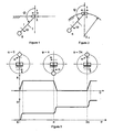
- Fig. 1
- presents a motion transformation mechanism with straight-line movement of the pendulum suspension;
- Fig. 2
- presents a motion transformation mechanism with circular movement of the pendulum suspension;
- Fig. 3
- presents the mode of control and the diagrams showing different phases of the mechanism motion;
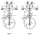
- Fig. 4
- presents a general structural design of the mechanism according to the invention with flexible fixing of the oscillating and driving levers;
- Fig. 5
- presents a structural design of the mechanism according to the invention with sliding connection between the oscillating and driving levers;
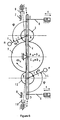
- Fig. 6
- presents a partially balanced mechanism according to the invention, which is realized by means of two pendulums; and
- Fig. 7
- presents a completely balanced mechanism according to the invention, which is realized by means of four pendulums.
- This inertial mechanism which provides the transformation of oscillating motion into one-way circular motion is a combination of a
pendulum 1 together with a movable suspension and a planetary gear. The mode of control of the newly formed mechanism with variable structure enables thependulum 1 one-way circular motion during the pendulum suspension oscillating movement. The transformation of motion is carried out so that for an angle of ϕ=0, π, 2π ... defining the position of the pendulum, there is a short-lived displacement of the pendulum suspension ofmagnitude 5 in the direction reverse to that of the instantaneous velocity of the mass m. - In other intervals the displacement of
pendulum suspension 1 is prevented by means of control signals and the appropriate elements which provide one-way linear motion ofpendulum 1 having angular velocity ω. - The application of the newly formed principle of motion transformation makes it possible to construct the mechanism, that is presented in Figure 4. The
pendulum 1 having the mass m and the length l is rigidly attached to aplanetary gear 2. These two elements are flexibly connected to the oscillatinglever 4 at the point A. Theplanetary gear 2 and asun wheel 3 are constantly kinematically coupled, so the gear wheel shaft is considered to be the output shaft of the mechanism which enables transmitting of the transformed motion energy.Driving levers lever 4. Traveling of the oscillatinglever 4 is prevented bylimit stops elements lever 5 and the oscillatinglever 4. - To provide partial mechanism balance it is possible to use two
pendulums sun wheel 3, presented in Figure 6. The positions of bothpendulums lever 4 are identical, and in case of identical parameters of thependulum 1, the vertical forces of the mechanism are balanced. - To provide complete mechanism balance it is necessary to design a structure presented in Figure 7, which includes two partially, balanced mechanisms. Sun
wheels - The newly formed principle of motion transformation together with the suggested structural design and the mode of control enable modeling of the mechanism providing for the transformation of the oscillating into one-way circular motion which has a high coefficient of efficiency and is expected to be broadly applied to the internal combustion engines. The advantage of this mechanism is especially important in cases of oxygen-hydrogen mixture used as fuel producing power due to its impulsive force action during combustion.
Claims (3)
- An inertial mechanism for transformation of short impulsive oscillatory displacements of a suspension point (A) into a one-way circular motion characterized by an oscillating lever. (4) which has its rotational axis correspondent to that of an output sun wheel (3) and is attached to the suspension point (A) of a pendulum (1) and further attached to flexibly connected driving levers (5, 6); said pendulum (1) of a mass (m) being firmly fixed to a planetary gear wheel (2); said planetary gear wheel (2) being constantly coupled with the sun wheel (3); and pairs of limit-stops (7, 8) and cut-out elements (9, 10) that alternatively make connection through their end parts with the oscillating lever (4) within intervals of its resting.
- The inertial mechanism according to claim 1, characterized in that it comprises two pendulums (1, 11), each rigidly attached to one of two planetary gear wheels (2, 12), whereas the planetary gear wheels (2, 12) are constantly coupled with the outlet sun wheel (3), and whereas the planetary gear wheels (2, 12) are located symmetrically in reference to the axis of rotation of the sun wheel (3).
- An inertial mechanism including two mechanisms according to claim 2, characterized by the mutual constant kinematic mesh of the sun wheels (3, 13).
Applications Claiming Priority (3)
| Application Number | Priority Date | Filing Date | Title |
|---|---|---|---|
| YU39902 | 2002-05-31 | ||
| YUP039902 | 2002-05-31 | ||
| PCT/YU2003/000015 WO2003102376A2 (en) | 2002-05-31 | 2003-05-28 | Inertial mechanism enabling transformation of an oscillatory motion into a one-way circular motion |
Publications (2)
| Publication Number | Publication Date |
|---|---|
| EP1514026A2 EP1514026A2 (en) | 2005-03-16 |
| EP1514026B1 true EP1514026B1 (en) | 2007-03-28 |
Family
ID=29712749
Family Applications (1)
| Application Number | Title | Priority Date | Filing Date |
|---|---|---|---|
| EP03756410A Expired - Lifetime EP1514026B1 (en) | 2002-05-31 | 2003-05-28 | Inertia mechanism enabling transformation of an oscillatory motion into a one-way circular motion |
Country Status (5)
| Country | Link |
|---|---|
| EP (1) | EP1514026B1 (en) |
| AT (1) | ATE358233T1 (en) |
| AU (1) | AU2003273549A1 (en) |
| DE (1) | DE60312858T2 (en) |
| WO (1) | WO2003102376A2 (en) |
Cited By (1)
| Publication number | Priority date | Publication date | Assignee | Title |
|---|---|---|---|---|
| RU2411139C1 (en) * | 2009-08-14 | 2011-02-10 | Геннадий Петрович Какуша | Universal transport facility to move in space |
Families Citing this family (2)
| Publication number | Priority date | Publication date | Assignee | Title |
|---|---|---|---|---|
| US7735386B2 (en) | 2004-06-18 | 2010-06-15 | Gravitational Energy Corporation | Power generation device |
| EP3115603B1 (en) * | 2015-07-10 | 2019-04-17 | Eichner, Dominik | Device and method for the production of electrical current |
Family Cites Families (8)
| Publication number | Priority date | Publication date | Assignee | Title |
|---|---|---|---|---|
| DE348110C (en) * | 1920-01-15 | 1922-01-30 | Det Tekniske Forsoegsaktiesels | Device for converting rotating into reciprocating motion |
| GB234317A (en) * | 1924-02-14 | 1925-05-14 | George Constantinesco | Improvements in power transmission |
| NL7804532A (en) * | 1977-05-11 | 1978-11-14 | Gerber Alfred | MULTI-CYLINDER PISTON MACHINE. |
| DE3014770C2 (en) * | 1980-04-17 | 1985-07-18 | Freudenau, Günter, 4800 Bielefeld | Centrifugal drive |
| US4516539A (en) * | 1983-09-26 | 1985-05-14 | Andreen John F | Internal combustion engine |
| DE3437841C1 (en) * | 1984-10-16 | 1986-04-24 | Günter 4800 Bielefeld Freudenau | Centrifugal internal combustion engine |
| WO1998026165A1 (en) * | 1995-11-01 | 1998-06-18 | Longwell Japan Co., Ltd. | Assembly for direct connection of internal combustion engine and machine driven |
| JPH1089075A (en) * | 1996-07-26 | 1998-04-07 | Hiroyasu Tanigawa | Device and method for making pendulum piston to serve as energy preserving cycle |
-
2003
- 2003-05-28 WO PCT/YU2003/000015 patent/WO2003102376A2/en not_active Ceased
- 2003-05-28 AU AU2003273549A patent/AU2003273549A1/en not_active Abandoned
- 2003-05-28 DE DE60312858T patent/DE60312858T2/en not_active Expired - Lifetime
- 2003-05-28 EP EP03756410A patent/EP1514026B1/en not_active Expired - Lifetime
- 2003-05-28 AT AT03756410T patent/ATE358233T1/en not_active IP Right Cessation
Cited By (1)
| Publication number | Priority date | Publication date | Assignee | Title |
|---|---|---|---|---|
| RU2411139C1 (en) * | 2009-08-14 | 2011-02-10 | Геннадий Петрович Какуша | Universal transport facility to move in space |
Also Published As
| Publication number | Publication date |
|---|---|
| AU2003273549A8 (en) | 2003-12-19 |
| WO2003102376B1 (en) | 2004-07-29 |
| WO2003102376A3 (en) | 2004-06-17 |
| WO2003102376A2 (en) | 2003-12-11 |
| ATE358233T1 (en) | 2007-04-15 |
| AU2003273549A1 (en) | 2003-12-19 |
| DE60312858D1 (en) | 2007-05-10 |
| EP1514026A2 (en) | 2005-03-16 |
| DE60312858T2 (en) | 2007-12-06 |
Similar Documents
| Publication | Publication Date | Title |
|---|---|---|
| WO2003086857A8 (en) | Aerodynamic lifting-thrusting propulsion device | |
| GB1589279A (en) | Apparatus for converting between rotary and reciprocal motion | |
| EP1636460B1 (en) | Linear into rotatory or vice versa motion convertor | |
| SK20793A3 (en) | Multiplying gear of kinetic energy with driving unit | |
| US4161889A (en) | Gyroscopic power transmission system | |
| US4295381A (en) | Crankless reciprocating engine and gyroscopic power transmission system | |
| EP1514026A2 (en) | Inertia mechanism enabling transformation of an oscillatory motion into a one-way circular motion | |
| US2758481A (en) | Devices for transmitting rotary motion | |
| EP2360396B1 (en) | Continuously variable transmission system | |
| Freudenstein et al. | Kinematic structure of mechanisms for fixed and variable-stroke axial-piston reciprocating machines | |
| JP6550569B2 (en) | Oscillating fluid power unit | |
| JP2003510528A (en) | Conversion from linear reciprocating motion to rotary motion | |
| CN108895123B (en) | Universal master-slave swing type gear transmission mechanism and synchronous swing method thereof | |
| RU2034170C1 (en) | Inertial centrifugal engine | |
| JP2000073701A (en) | Direct-coupled crank device for two linearly reciprocating movable bodies | |
| KR20240044692A (en) | Energy harvester using both roll or pitch motion | |
| EP4729771A1 (en) | Method and device for the sequential conversion of centrifugal and centripetal forces into mechanical work | |
| US3864982A (en) | Kinematic mechanism for the reversible conversion of reciprocating motion to rotary motion | |
| JP2009520146A (en) | Rotary piston machine consisting of two piston mounts arranged on a shaft | |
| RU2402707C2 (en) | Compound planetary gear | |
| RU2102642C1 (en) | Mechanism for converting motion | |
| JP2012503148A (en) | A device that converts reciprocating motion into rotational motion in a certain direction | |
| RU2026504C1 (en) | Vibration exciter of inertial motion | |
| RU2013606C1 (en) | Internal combustion engine | |
| RU67649U1 (en) | INTERNAL COMBUSTION ENGINE |
Legal Events
| Date | Code | Title | Description |
|---|---|---|---|
| PUAI | Public reference made under article 153(3) epc to a published international application that has entered the european phase |
Free format text: ORIGINAL CODE: 0009012 |
|
| 17P | Request for examination filed |
Effective date: 20041223 |
|
| AK | Designated contracting states |
Kind code of ref document: A2 Designated state(s): AT BE BG CH CY CZ DE DK EE ES FI FR GB GR HU IE IT LI LU MC NL PT RO SE SI SK TR |
|
| AX | Request for extension of the european patent |
Extension state: AL LT LV MK |
|
| DAX | Request for extension of the european patent (deleted) | ||
| GRAP | Despatch of communication of intention to grant a patent |
Free format text: ORIGINAL CODE: EPIDOSNIGR1 |
|
| GRAS | Grant fee paid |
Free format text: ORIGINAL CODE: EPIDOSNIGR3 |
|
| GRAA | (expected) grant |
Free format text: ORIGINAL CODE: 0009210 |
|
| AK | Designated contracting states |
Kind code of ref document: B1 Designated state(s): AT BE BG CH CY CZ DE DK EE ES FI FR GB GR HU IE IT LI LU MC NL PT RO SE SI SK TR |
|
| PG25 | Lapsed in a contracting state [announced via postgrant information from national office to epo] |
Ref country code: NL Free format text: LAPSE BECAUSE OF FAILURE TO SUBMIT A TRANSLATION OF THE DESCRIPTION OR TO PAY THE FEE WITHIN THE PRESCRIBED TIME-LIMIT Effective date: 20070328 Ref country code: FI Free format text: LAPSE BECAUSE OF FAILURE TO SUBMIT A TRANSLATION OF THE DESCRIPTION OR TO PAY THE FEE WITHIN THE PRESCRIBED TIME-LIMIT Effective date: 20070328 Ref country code: BE Free format text: LAPSE BECAUSE OF FAILURE TO SUBMIT A TRANSLATION OF THE DESCRIPTION OR TO PAY THE FEE WITHIN THE PRESCRIBED TIME-LIMIT Effective date: 20070328 Ref country code: AT Free format text: LAPSE BECAUSE OF FAILURE TO SUBMIT A TRANSLATION OF THE DESCRIPTION OR TO PAY THE FEE WITHIN THE PRESCRIBED TIME-LIMIT Effective date: 20070328 Ref country code: SI Free format text: LAPSE BECAUSE OF FAILURE TO SUBMIT A TRANSLATION OF THE DESCRIPTION OR TO PAY THE FEE WITHIN THE PRESCRIBED TIME-LIMIT Effective date: 20070328 Ref country code: CH Free format text: LAPSE BECAUSE OF FAILURE TO SUBMIT A TRANSLATION OF THE DESCRIPTION OR TO PAY THE FEE WITHIN THE PRESCRIBED TIME-LIMIT Effective date: 20070328 Ref country code: LI Free format text: LAPSE BECAUSE OF FAILURE TO SUBMIT A TRANSLATION OF THE DESCRIPTION OR TO PAY THE FEE WITHIN THE PRESCRIBED TIME-LIMIT Effective date: 20070328 |
|
| REG | Reference to a national code |
Ref country code: GB Ref legal event code: FG4D |
|
| REG | Reference to a national code |
Ref country code: CH Ref legal event code: EP |
|
| REF | Corresponds to: |
Ref document number: 60312858 Country of ref document: DE Date of ref document: 20070510 Kind code of ref document: P |
|
| REG | Reference to a national code |
Ref country code: IE Ref legal event code: FG4D |
|
| PG25 | Lapsed in a contracting state [announced via postgrant information from national office to epo] |
Ref country code: SE Free format text: LAPSE BECAUSE OF FAILURE TO SUBMIT A TRANSLATION OF THE DESCRIPTION OR TO PAY THE FEE WITHIN THE PRESCRIBED TIME-LIMIT Effective date: 20070628 |
|
| PG25 | Lapsed in a contracting state [announced via postgrant information from national office to epo] |
Ref country code: ES Free format text: LAPSE BECAUSE OF FAILURE TO SUBMIT A TRANSLATION OF THE DESCRIPTION OR TO PAY THE FEE WITHIN THE PRESCRIBED TIME-LIMIT Effective date: 20070709 |
|
| PG25 | Lapsed in a contracting state [announced via postgrant information from national office to epo] |
Ref country code: PT Free format text: LAPSE BECAUSE OF FAILURE TO SUBMIT A TRANSLATION OF THE DESCRIPTION OR TO PAY THE FEE WITHIN THE PRESCRIBED TIME-LIMIT Effective date: 20070828 |
|
| REG | Reference to a national code |
Ref country code: CH Ref legal event code: PL |
|
| NLV1 | Nl: lapsed or annulled due to failure to fulfill the requirements of art. 29p and 29m of the patents act | ||
| EN | Fr: translation not filed | ||
| PG25 | Lapsed in a contracting state [announced via postgrant information from national office to epo] |
Ref country code: SK Free format text: LAPSE BECAUSE OF FAILURE TO SUBMIT A TRANSLATION OF THE DESCRIPTION OR TO PAY THE FEE WITHIN THE PRESCRIBED TIME-LIMIT Effective date: 20070328 |
|
| PG25 | Lapsed in a contracting state [announced via postgrant information from national office to epo] |
Ref country code: CZ Free format text: LAPSE BECAUSE OF FAILURE TO SUBMIT A TRANSLATION OF THE DESCRIPTION OR TO PAY THE FEE WITHIN THE PRESCRIBED TIME-LIMIT Effective date: 20070328 Ref country code: RO Free format text: LAPSE BECAUSE OF FAILURE TO SUBMIT A TRANSLATION OF THE DESCRIPTION OR TO PAY THE FEE WITHIN THE PRESCRIBED TIME-LIMIT Effective date: 20070328 |
|
| PG25 | Lapsed in a contracting state [announced via postgrant information from national office to epo] |
Ref country code: DK Free format text: LAPSE BECAUSE OF FAILURE TO SUBMIT A TRANSLATION OF THE DESCRIPTION OR TO PAY THE FEE WITHIN THE PRESCRIBED TIME-LIMIT Effective date: 20070328 Ref country code: MC Free format text: LAPSE BECAUSE OF NON-PAYMENT OF DUE FEES Effective date: 20070531 |
|
| PLBE | No opposition filed within time limit |
Free format text: ORIGINAL CODE: 0009261 |
|
| STAA | Information on the status of an ep patent application or granted ep patent |
Free format text: STATUS: NO OPPOSITION FILED WITHIN TIME LIMIT |
|
| GBPC | Gb: european patent ceased through non-payment of renewal fee |
Effective date: 20070628 |
|
| 26N | No opposition filed |
Effective date: 20080102 |
|
| PG25 | Lapsed in a contracting state [announced via postgrant information from national office to epo] |
Ref country code: FR Free format text: LAPSE BECAUSE OF FAILURE TO SUBMIT A TRANSLATION OF THE DESCRIPTION OR TO PAY THE FEE WITHIN THE PRESCRIBED TIME-LIMIT Effective date: 20071116 Ref country code: GR Free format text: LAPSE BECAUSE OF FAILURE TO SUBMIT A TRANSLATION OF THE DESCRIPTION OR TO PAY THE FEE WITHIN THE PRESCRIBED TIME-LIMIT Effective date: 20070629 Ref country code: IT Free format text: LAPSE BECAUSE OF FAILURE TO SUBMIT A TRANSLATION OF THE DESCRIPTION OR TO PAY THE FEE WITHIN THE PRESCRIBED TIME-LIMIT Effective date: 20070328 |
|
| PG25 | Lapsed in a contracting state [announced via postgrant information from national office to epo] |
Ref country code: GB Free format text: LAPSE BECAUSE OF NON-PAYMENT OF DUE FEES Effective date: 20070628 Ref country code: IE Free format text: LAPSE BECAUSE OF NON-PAYMENT OF DUE FEES Effective date: 20070528 |
|
| PG25 | Lapsed in a contracting state [announced via postgrant information from national office to epo] |
Ref country code: FR Free format text: LAPSE BECAUSE OF FAILURE TO SUBMIT A TRANSLATION OF THE DESCRIPTION OR TO PAY THE FEE WITHIN THE PRESCRIBED TIME-LIMIT Effective date: 20070328 |
|
| PG25 | Lapsed in a contracting state [announced via postgrant information from national office to epo] |
Ref country code: EE Free format text: LAPSE BECAUSE OF FAILURE TO SUBMIT A TRANSLATION OF THE DESCRIPTION OR TO PAY THE FEE WITHIN THE PRESCRIBED TIME-LIMIT Effective date: 20070328 |
|
| PG25 | Lapsed in a contracting state [announced via postgrant information from national office to epo] |
Ref country code: CY Free format text: LAPSE BECAUSE OF FAILURE TO SUBMIT A TRANSLATION OF THE DESCRIPTION OR TO PAY THE FEE WITHIN THE PRESCRIBED TIME-LIMIT Effective date: 20070328 |
|
| PG25 | Lapsed in a contracting state [announced via postgrant information from national office to epo] |
Ref country code: BG Free format text: LAPSE BECAUSE OF FAILURE TO SUBMIT A TRANSLATION OF THE DESCRIPTION OR TO PAY THE FEE WITHIN THE PRESCRIBED TIME-LIMIT Effective date: 20070628 Ref country code: LU Free format text: LAPSE BECAUSE OF NON-PAYMENT OF DUE FEES Effective date: 20070528 |
|
| PG25 | Lapsed in a contracting state [announced via postgrant information from national office to epo] |
Ref country code: TR Free format text: LAPSE BECAUSE OF FAILURE TO SUBMIT A TRANSLATION OF THE DESCRIPTION OR TO PAY THE FEE WITHIN THE PRESCRIBED TIME-LIMIT Effective date: 20070328 Ref country code: HU Free format text: LAPSE BECAUSE OF FAILURE TO SUBMIT A TRANSLATION OF THE DESCRIPTION OR TO PAY THE FEE WITHIN THE PRESCRIBED TIME-LIMIT Effective date: 20070929 |
|
| PGFP | Annual fee paid to national office [announced via postgrant information from national office to epo] |
Ref country code: DE Payment date: 20130529 Year of fee payment: 11 |
|
| REG | Reference to a national code |
Ref country code: DE Ref legal event code: R119 Ref document number: 60312858 Country of ref document: DE |
|
| REG | Reference to a national code |
Ref country code: DE Ref legal event code: R119 Ref document number: 60312858 Country of ref document: DE Effective date: 20141202 |
|
| PG25 | Lapsed in a contracting state [announced via postgrant information from national office to epo] |
Ref country code: DE Free format text: LAPSE BECAUSE OF NON-PAYMENT OF DUE FEES Effective date: 20141202 |