EP1513468B1 - Rapid exchange catheters usable with embolic protection devices - Google Patents
Rapid exchange catheters usable with embolic protection devices Download PDFInfo
- Publication number
- EP1513468B1 EP1513468B1 EP03741887.8A EP03741887A EP1513468B1 EP 1513468 B1 EP1513468 B1 EP 1513468B1 EP 03741887 A EP03741887 A EP 03741887A EP 1513468 B1 EP1513468 B1 EP 1513468B1
- Authority
- EP
- European Patent Office
- Prior art keywords
- distal
- catheter
- port
- proximal
- embolic protection
- Prior art date
- Legal status (The legal status is an assumption and is not a legal conclusion. Google has not performed a legal analysis and makes no representation as to the accuracy of the status listed.)
- Expired - Lifetime
Links
- 230000003073 embolic effect Effects 0.000 title claims description 153
- 239000012530 fluid Substances 0.000 claims description 5
- 238000000034 method Methods 0.000 description 45
- 239000000463 material Substances 0.000 description 8
- 210000004351 coronary vessel Anatomy 0.000 description 6
- 238000007689 inspection Methods 0.000 description 6
- 208000007536 Thrombosis Diseases 0.000 description 5
- 239000012634 fragment Substances 0.000 description 5
- 229920000642 polymer Polymers 0.000 description 5
- 208000031481 Pathologic Constriction Diseases 0.000 description 4
- 229920002614 Polyether block amide Polymers 0.000 description 4
- 230000017531 blood circulation Effects 0.000 description 4
- 230000001225 therapeutic effect Effects 0.000 description 4
- 206010002383 Angina Pectoris Diseases 0.000 description 3
- 239000004677 Nylon Substances 0.000 description 3
- 239000004642 Polyimide Substances 0.000 description 3
- 239000000853 adhesive Substances 0.000 description 3
- 230000001070 adhesive effect Effects 0.000 description 3
- 230000000712 assembly Effects 0.000 description 3
- 238000000429 assembly Methods 0.000 description 3
- 238000000576 coating method Methods 0.000 description 3
- 238000001914 filtration Methods 0.000 description 3
- 210000004013 groin Anatomy 0.000 description 3
- 229920001903 high density polyethylene Polymers 0.000 description 3
- 239000004700 high-density polyethylene Substances 0.000 description 3
- 208000010125 myocardial infarction Diseases 0.000 description 3
- 229920001778 nylon Polymers 0.000 description 3
- 239000002245 particle Substances 0.000 description 3
- 229920001721 polyimide Polymers 0.000 description 3
- 238000011084 recovery Methods 0.000 description 3
- 230000036262 stenosis Effects 0.000 description 3
- 208000037804 stenosis Diseases 0.000 description 3
- 206010003210 Arteriosclerosis Diseases 0.000 description 2
- 208000037260 Atherosclerotic Plaque Diseases 0.000 description 2
- VGGSQFUCUMXWEO-UHFFFAOYSA-N Ethene Chemical compound C=C VGGSQFUCUMXWEO-UHFFFAOYSA-N 0.000 description 2
- 210000000709 aorta Anatomy 0.000 description 2
- 210000001105 femoral artery Anatomy 0.000 description 2
- 230000006870 function Effects 0.000 description 2
- 238000013152 interventional procedure Methods 0.000 description 2
- 230000003902 lesion Effects 0.000 description 2
- 229920001684 low density polyethylene Polymers 0.000 description 2
- 239000004702 low-density polyethylene Substances 0.000 description 2
- 230000002093 peripheral effect Effects 0.000 description 2
- 229920001296 polysiloxane Polymers 0.000 description 2
- 229920002635 polyurethane Polymers 0.000 description 2
- 239000004814 polyurethane Substances 0.000 description 2
- 239000002904 solvent Substances 0.000 description 2
- 229910001220 stainless steel Inorganic materials 0.000 description 2
- 239000010935 stainless steel Substances 0.000 description 2
- 238000002560 therapeutic procedure Methods 0.000 description 2
- 210000005166 vasculature Anatomy 0.000 description 2
- 238000003466 welding Methods 0.000 description 2
- BLDFSDCBQJUWFG-UHFFFAOYSA-N 2-(methylamino)-1,2-diphenylethanol Chemical compound C=1C=CC=CC=1C(NC)C(O)C1=CC=CC=C1 BLDFSDCBQJUWFG-UHFFFAOYSA-N 0.000 description 1
- OYPRJOBELJOOCE-UHFFFAOYSA-N Calcium Chemical compound [Ca] OYPRJOBELJOOCE-UHFFFAOYSA-N 0.000 description 1
- HTTJABKRGRZYRN-UHFFFAOYSA-N Heparin Chemical compound OC1C(NC(=O)C)C(O)OC(COS(O)(=O)=O)C1OC1C(OS(O)(=O)=O)C(O)C(OC2C(C(OS(O)(=O)=O)C(OC3C(C(O)C(O)C(O3)C(O)=O)OS(O)(=O)=O)C(CO)O2)NS(O)(=O)=O)C(C(O)=O)O1 HTTJABKRGRZYRN-UHFFFAOYSA-N 0.000 description 1
- 229920000106 Liquid crystal polymer Polymers 0.000 description 1
- 239000004977 Liquid-crystal polymers (LCPs) Substances 0.000 description 1
- 208000002193 Pain Diseases 0.000 description 1
- 239000004696 Poly ether ether ketone Substances 0.000 description 1
- 229920006099 Vestamid® Polymers 0.000 description 1
- 230000002965 anti-thrombogenic effect Effects 0.000 description 1
- 210000001367 artery Anatomy 0.000 description 1
- JUPQTSLXMOCDHR-UHFFFAOYSA-N benzene-1,4-diol;bis(4-fluorophenyl)methanone Chemical compound OC1=CC=C(O)C=C1.C1=CC(F)=CC=C1C(=O)C1=CC=C(F)C=C1 JUPQTSLXMOCDHR-UHFFFAOYSA-N 0.000 description 1
- 230000000903 blocking effect Effects 0.000 description 1
- 239000008280 blood Substances 0.000 description 1
- 210000004369 blood Anatomy 0.000 description 1
- 210000004204 blood vessel Anatomy 0.000 description 1
- 229910052791 calcium Inorganic materials 0.000 description 1
- 239000011575 calcium Substances 0.000 description 1
- 230000000747 cardiac effect Effects 0.000 description 1
- 238000007887 coronary angioplasty Methods 0.000 description 1
- 230000006735 deficit Effects 0.000 description 1
- 230000002939 deleterious effect Effects 0.000 description 1
- 230000010339 dilation Effects 0.000 description 1
- 230000003292 diminished effect Effects 0.000 description 1
- 230000000694 effects Effects 0.000 description 1
- 230000010102 embolization Effects 0.000 description 1
- 229960002897 heparin Drugs 0.000 description 1
- 229920000669 heparin Polymers 0.000 description 1
- 239000000017 hydrogel Substances 0.000 description 1
- 230000003907 kidney function Effects 0.000 description 1
- 229920000126 latex Polymers 0.000 description 1
- 239000004816 latex Substances 0.000 description 1
- 239000003550 marker Substances 0.000 description 1
- 229920001179 medium density polyethylene Polymers 0.000 description 1
- 239000004701 medium-density polyethylene Substances 0.000 description 1
- HLXZNVUGXRDIFK-UHFFFAOYSA-N nickel titanium Chemical compound [Ti].[Ti].[Ti].[Ti].[Ti].[Ti].[Ti].[Ti].[Ti].[Ti].[Ti].[Ni].[Ni].[Ni].[Ni].[Ni].[Ni].[Ni].[Ni].[Ni].[Ni].[Ni].[Ni].[Ni].[Ni] HLXZNVUGXRDIFK-UHFFFAOYSA-N 0.000 description 1
- 229910001000 nickel titanium Inorganic materials 0.000 description 1
- 230000003836 peripheral circulation Effects 0.000 description 1
- 229920002530 polyetherether ketone Polymers 0.000 description 1
- 229920000139 polyethylene terephthalate Polymers 0.000 description 1
- 239000005020 polyethylene terephthalate Substances 0.000 description 1
- 210000003752 saphenous vein Anatomy 0.000 description 1
- 239000007779 soft material Substances 0.000 description 1
- 239000007787 solid Substances 0.000 description 1
- 238000001356 surgical procedure Methods 0.000 description 1
- 238000013151 thrombectomy Methods 0.000 description 1
- 230000001052 transient effect Effects 0.000 description 1
- XLYOFNOQVPJJNP-UHFFFAOYSA-N water Substances O XLYOFNOQVPJJNP-UHFFFAOYSA-N 0.000 description 1
Images


Classifications
-
- A—HUMAN NECESSITIES
- A61—MEDICAL OR VETERINARY SCIENCE; HYGIENE
- A61F—FILTERS IMPLANTABLE INTO BLOOD VESSELS; PROSTHESES; DEVICES PROVIDING PATENCY TO, OR PREVENTING COLLAPSING OF, TUBULAR STRUCTURES OF THE BODY, e.g. STENTS; ORTHOPAEDIC, NURSING OR CONTRACEPTIVE DEVICES; FOMENTATION; TREATMENT OR PROTECTION OF EYES OR EARS; BANDAGES, DRESSINGS OR ABSORBENT PADS; FIRST-AID KITS
- A61F2/00—Filters implantable into blood vessels; Prostheses, i.e. artificial substitutes or replacements for parts of the body; Appliances for connecting them with the body; Devices providing patency to, or preventing collapsing of, tubular structures of the body, e.g. stents
- A61F2/01—Filters implantable into blood vessels
- A61F2/011—Instruments for their placement or removal
-
- A—HUMAN NECESSITIES
- A61—MEDICAL OR VETERINARY SCIENCE; HYGIENE
- A61F—FILTERS IMPLANTABLE INTO BLOOD VESSELS; PROSTHESES; DEVICES PROVIDING PATENCY TO, OR PREVENTING COLLAPSING OF, TUBULAR STRUCTURES OF THE BODY, e.g. STENTS; ORTHOPAEDIC, NURSING OR CONTRACEPTIVE DEVICES; FOMENTATION; TREATMENT OR PROTECTION OF EYES OR EARS; BANDAGES, DRESSINGS OR ABSORBENT PADS; FIRST-AID KITS
- A61F2/00—Filters implantable into blood vessels; Prostheses, i.e. artificial substitutes or replacements for parts of the body; Appliances for connecting them with the body; Devices providing patency to, or preventing collapsing of, tubular structures of the body, e.g. stents
- A61F2/01—Filters implantable into blood vessels
- A61F2002/018—Filters implantable into blood vessels made from tubes or sheets of material, e.g. by etching or laser-cutting
-
- A—HUMAN NECESSITIES
- A61—MEDICAL OR VETERINARY SCIENCE; HYGIENE
- A61F—FILTERS IMPLANTABLE INTO BLOOD VESSELS; PROSTHESES; DEVICES PROVIDING PATENCY TO, OR PREVENTING COLLAPSING OF, TUBULAR STRUCTURES OF THE BODY, e.g. STENTS; ORTHOPAEDIC, NURSING OR CONTRACEPTIVE DEVICES; FOMENTATION; TREATMENT OR PROTECTION OF EYES OR EARS; BANDAGES, DRESSINGS OR ABSORBENT PADS; FIRST-AID KITS
- A61F2230/00—Geometry of prostheses classified in groups A61F2/00 - A61F2/26 or A61F2/82 or A61F9/00 or A61F11/00 or subgroups thereof
- A61F2230/0002—Two-dimensional shapes, e.g. cross-sections
- A61F2230/0004—Rounded shapes, e.g. with rounded corners
- A61F2230/0008—Rounded shapes, e.g. with rounded corners elliptical or oval
-
- A—HUMAN NECESSITIES
- A61—MEDICAL OR VETERINARY SCIENCE; HYGIENE
- A61F—FILTERS IMPLANTABLE INTO BLOOD VESSELS; PROSTHESES; DEVICES PROVIDING PATENCY TO, OR PREVENTING COLLAPSING OF, TUBULAR STRUCTURES OF THE BODY, e.g. STENTS; ORTHOPAEDIC, NURSING OR CONTRACEPTIVE DEVICES; FOMENTATION; TREATMENT OR PROTECTION OF EYES OR EARS; BANDAGES, DRESSINGS OR ABSORBENT PADS; FIRST-AID KITS
- A61F2230/00—Geometry of prostheses classified in groups A61F2/00 - A61F2/26 or A61F2/82 or A61F9/00 or A61F11/00 or subgroups thereof
- A61F2230/0063—Three-dimensional shapes
- A61F2230/0073—Quadric-shaped
- A61F2230/008—Quadric-shaped paraboloidal
Definitions
- a guide wire and guide catheter are inserted into the femoral artery of a patient near the groin, advanced through the artery, over the aorta, and into a coronary artery.
- An inflatable balloon is then advanced into the coronary artery, across a stenosis or blockage, and the balloon inflated to dilate the blockage and open a flow channel through the partially blocked vessel region.
- One or more stents may also be placed across the dilated region or regions.
- Consequences of embolization include stroke, diminished renal function, and impairment of peripheral circulation possibly leading to pain and imputation.
- Distal embolic protection devices can be delivered over guide wires and within guide catheters.
- the distal embolic protection methods are normally practiced ancillary to another medical procedure, for example PTCA with stenting or atherectomy.
- the distal embolic protection procedure typically protects downstream regions from emboli resulting from practicing the therapeutic interventional procedure.
- the treating physician must advance a guide wire over the aorta and into a coronary ostium. Advancing the guide wire through tortuous vessels from a femoral artery approach can be difficult, and vary with both the patient and the vessel site to be treated.
- Guide wires are typically selected by the treating physician, based on facts specific to the patient and therapeutic situation, and also on the training, experiences, and preferences of the physician.
- a physician may have become very efficient in using a specific guide wire to identify the left coronary ostium and then advance a balloon catheter over the positioned guide wire.
- the efficacy of the procedure may depend on the physician being able to use their favored guide wire.
- the distal end port and the distal sidewall port can be dimensioned to allow passage of a guide wire.
- the proximal sidewall port can be dimensioned to allow passage of an embolic protection device wire shaft through the port.
- the distal end port, the distal sidewall port, and the proximal sidewall port are all dimensioned to allow passage of a 0.014 inch (0.035 cm) outside diameter wire through the ports.
- the catheter inside diameter can be dimensioned to allow passage of an embolic filter in a compressed state.
- Some catheters are formed of a tube extending from the distal end to the proximal end, while other catheters are formed of a tube in the distal region and a shaft or smaller tube in the intermediate and proximal regions.
- the present invention also includes catheter assemblies which can include a two port catheter, a guide wire, a distal embolic protection device, and a guide catheter adapted to receive the catheter within.
- the guide wire proximal end can be threaded into the catheter distal end port and out of the catheter distal sidewall port to extend proximally along the exterior of the catheter.
- the catheter carrying the distal embolic protection device can then be advanced distally over the guide wire to near the target site.
- the catheter is advanced across the target region while in other methods the catheter is advanced to a position proximal of the target region.
- the guide wire can then be proximally retracted, and pulled from within the catheter through the distal sidewall port.
- the distal filter element is then advanced distally out of the two port catheter distal end port and allowed to expand in some methods.
- the catheter can be proximally retracted from the patient by grasping the proximal end of the distal embolic protection device shaft while proximally retracting the catheter.
- the distal embolic protection device wire shaft extends through the catheter distal region, only a short added length of wire shaft is required, rather than a double length wire shaft as would be required by a conventional catheter.
- the back loading of the guide wire through the distal end port and out of the distal sidewall port is aided by a collapsible guide wire tube extending from near the distal end port to the distal sidewall port.
- the catheter may be used to recover the embolic protection device.
- the proximal end of the embolic protection device shaft proximal end is threaded into the distal end port and out the proximal sidewall port.
- the catheter is advanced into the patient along the device shaft until the catheter tip is immediately proximal to the embolic protection device.
- the embolic protection device may be partially or totally recovered into the lumen of the catheter by effecting relative motion between the device shaft and the catheter. Subsequently the catheter/embolic protection device can be withdrawn as a unit from patient's body.
- the three port catheter can be formed of a tube over its entire length or be tubular only in the distal region, being formed of a shaft in the intermediate and proximal regions.
- the three port catheter can include a distal end port dimensioned to allow passage of a guide wire through the port, but not being large enough to allow passage of a filter element.
- the reduced size of the distal end port allows for a reduced profile catheter distal end, which can now be narrowly tapered to allow passage through smaller diameter vessels and past more highly stenosed vessel regions.
- the distal end port can also be tapered to perfectly match the guide wire so as to facilitate smooth passage across vessel irregularities such as calcium spicules or implanted stents.
- the three port catheter can include a distal sidewall port, an intermediate sidewall port, and a proximal sidewall port.
- the intermediate sidewall port can be dimensioned to allow passage of a guide wire through the port, and can function in a similar manner to the distal sidewall port described with respect to the two port catheter.
- the intermediate port is substantially circumferentially aligned with the distal sidewall port.
- the distal end port is disposed off center from the central longitudinal axis of the catheter while the distal sidewall port is substantially aligned with the central longitudinal axis of the catheter such that distal advancement of the filter element is directed substantially toward the distal sidewall port rather than the distal end port.
- a third catheter according to the present invention includes a tube having a normally open slot extending along most of the tube length.
- the slotted catheter preferably has a distal end port dimensioned to allow passage of a guide wire and a distal embolic protection device filter through the port.
- the catheter preferably has a distal sidewall port to allow passage of a guide wire through the distal sidewall port.
- the distal sidewall port can, but need not, be formed as a widened or enlarged portion of the longitudinal slot extending through the sidewall.
- the catheter preferably has an unslotted distal most region to provide column strength for allowing the catheter to be pushed across narrowed, stenosed vessel regions.
- Some catheters include a funnel portion disposed near the proximal region to aid in introducing the distal embolic protection device filter into the lumen within the catheter.
- the slot is preferably at least about 0.001 inch (0.0025 cm) in width, and can be about 0.005 inch (0.0027 cm) or even 0.014 inch (0.035 cm) in width.
- the slot is preferably dimensioned to inhibit the free, transverse movement of a guide wire or distal embolic protection device wire shaft through the slot.
- the catheter body is preferably sufficiently resilient to allow the forced, transverse movement of a wire shaft or guide wire through the slot when such movement is desired.
- the distal-most tip can be located off center, with the center of the distal profile being occupied by the slot.
- the distal-most sidewall region can be curved or bent down to form an end wall containing the off-center, distal-most tip.
- a guide catheter can be advanced to near the target site, followed by the advancement of a guide wire, as with the two and three port catheters previously discussed.
- the guide wire proximal end can be threaded into the distal end port and out of the distal sidewall port, to extend along the outside of the catheter.
- the distal embolic protection device can be preloaded into the distal region of the slotted catheter. In some embodiments, the distal embolic protection device is front loaded by distally advancing the device into the proximal end of the catheter and further into the catheter distal region.
- the distal embolic protection device is back loaded by proximally threading the distal embolic protection device wire shaft through the catheter distal end port and further proximally through the catheter until the wire shaft exits the proximal end of the catheter, and the filter element is disposed proximal of the distal sidewall port of the catheter.
- the catheter carrying the distal embolic protection device can then be advanced over the guide wire to near the target site or across the stenosis.
- the guide wire can be proximally retracted from the catheter, followed by the deployment of the filter element through the catheter distal end port.
- the distal embolic protection device wire shaft can be forced transversely through the slot in the catheter beginning near the catheter proximal end.
- the wire shaft can be held substantially stationary, while the catheter is proximally retracted from the patient.
- the proximal retraction can be continued until the wire shaft is disposed within the distal sidewall port of the slot, whereupon the wire shaft can be grasped distal of the catheter distal end port and the catheter fully removed from the patient.
- the catheter can be advanced to across the stenosis or near the target site over the guide wire, with the catheter not yet carrying the distal embolic protection device.
- the distal embolic protection device can later be advanced through the lumen of the slotted catheter to the catheter distal region.
- the catheter can also be used to recover an embolic protection device as described for the two port catheter.
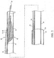
- Figure 1 illustrates a distal embolic protection device assembly 20 which can be used to deliver a distal embolic protection device to a target site within the vasculature.
- Assembly 20 includes a delivery/recovery catheter 24 disposed within a guide catheter 22.
- the delivery/recovery catheter can be used to both deliver and recover a distal embolic protection filter.
- the term "delivery catheter”, as used herein, should be understood as including a delivery catheter that can also be used to recover a particulate containing filter.
- Delivery catheter 24 includes a guide wire 19 and a distal embolic protection device 26 disposed within. The proximal end of assembly 20 is illustrated without any hub or Luer fitting to more clearly illustrate the invention.
- Guide catheter 22 includes a distal end 28, a distal region 32, a proximal region 34, a proximal end 36, and a lumen 30 extending therethrough. Guide catheters are well known to those skilled in the art and will not be further explained. Delivery catheter 24 can be referred to as a "two-port" catheter, as it has two sidewall ports. Delivery catheter 24 includes a distal end 40, a distal region 42, a distal port or distal sidewall port 48, a proximal port or proximal sidewall port 50, a proximal region 44, a proximal end 46, and a lumen 38 extending therethrough.
- proximal region 44 of delivery catheter 24 is formed by a shaft rather than a tube, with catheter lumen 38 extending through only a distal region of the delivery device.
- Delivery catheter 24 also includes a distal end port or distal tip port 41, formed at the distal end of the catheter.
- proximal region 44 which is proximal of proximal port 50, can be formed by a tube which has been transversely slit and pressed downward proximal of proximal port 50.
- Guide wire 19 may be seen to include a distal tip 60, a distal region 62, a wire or shaft 64, a proximal region 65, and a proximal end 66.
- Guide wire 19 may be seen to extend proximally from distal tip 60, within catheter lumen 38, then extending outwardly through distal sidewall port 48 to extend proximally along the outside of delivery catheter 24.
- guide wire 19 has been threaded through delivery catheter distal sidewall port 48.
- guide wire 19 is advanced through guide catheter 22, with guide wire proximal end 66 yet to be threaded into delivery catheter distal end port 41 and out delivery catheter distal sidewall port 48.
- proximal end 66 of the guide wire is threaded into distal end 41 of the catheter and out through distal sidewall port 48.
- the wire back loading can be aided by arcing the distal region of delivery catheter 24, such that the guide wire proximal end 66 is pressed against the inner wall of the catheter near distal sidewall port 48.
- Distal embolic protection device 26 may be seen to include a shaft or wire 74 including a distal region 72 coupled to a distal filter 70.
- Distal filter 70 can be viewed as one type of distal emboli protection element.
- Other distal protection elements which can be included as part of the present invention are occlusive emboli protection elements, including expandable or inflatable elements for blocking fluid flow through a vessel. Unless otherwise indicated, occlusive elements should be considered as interchangeable with filter elements in the present invention.
- Distal embolic protection device shaft 74 may be seen to have a proximal region 76 and a proximal end 78 extending proximally from guide catheter 22.
- Filter 70 is shown in a compressed, radially reduced profile configuration as a result of disposition within delivery catheter 24. In a preferred embodiment, filter 70 is biased to expand radially outward when not constrained by delivery catheter 24.
- Distal embolic protection device filter 70 may be seen disposed between proximal sidewall port 50 and distal sidewall port 48 in intermediate region 45.
- Distal embolic protection device shaft 74 may be seen to lie within catheter lumen 38 distal of proximal port 50, then extend through proximal port 50 to the exterior of delivery catheter 24, then extend along the outside of delivery catheter 24 over its length.
- guide wire 19 is formed of stainless steel or Nitinol and has a safety, spring tip.
- Guide wire 19 can have a length of between about 130 and 180 cm. in some embodiments.
- Guide wire 19 can have radiopaque marker bands along its length.
- Guide wire 19 may also have an outside diameter of between about 0.009 and 0.035 inch (0.023 to 0.089 cm) (in some embodiments, and about 0.014 inch (0.036 cm) in a commonly used embodiment.
- Delivery catheter 24 can be formed of materials well known to those skilled in the art.
- the distal region of catheter 24 is formed of a softer, more pliable material than the more proximal regions of the catheter.
- catheter distal region 42 is formed of a rather floppy, soft material.
- the distal region is formed of a polymer such as LDPE, MDPE, or PEBAX.
- This floppy distal region can be coupled to stiffer intermediate and proximal regions formed of polymers such as HDPE, VESTAMID, or Polyimide.
- the floppy distal region can provide a distal region better adapted to advance through tortuous vessels while the more rigid intermediate and proximal regions can provide pushability.
- Distal embolic protection device 26 is preferably an expandable filter device.
- Filter 70 is well known to those skilled in the art and can be a filter as disclosed in U.S. Pat. No. 6,325,815 , European Patent Application No. 1181900 A2 , and PCT Pub. No. WO 96/0195 .
- distal embolic protection device shaft 74 is formed of stainless steel and has an outside diameter of about 0.014 inch (0.036 cm).
- the distance between delivery catheter distal sidewall port 48 and distal end 40 is between about 5 and 30 cm.
- proximal sidewall port 50 is located at a distance of between about 15 and 50 cm. from distal end 40.
- distal sidewall port 48 is located between about 5 and 20 cm. distal of proximal sidewall port 50, and the delivery catheter can be about 3 Fr. in diameter and about 135 cm long. From inspection of Figure 1 , it may be seen that guide wire 19 is within lumen 38 only over its length between catheter distal end 40 and catheter distal sidewall port 48.
- FIG. 1 When advancing delivery catheter 24 over guide wire 19, only the added length between catheter distal end 40 and distal sidewall port 48 need be added to guide wire 19, rather than doubling its length.
- Inspection of Figure 1 also illustrates that distal embolic protection device shaft 74 is only within lumen 38 of catheter 24 over the length between catheter distal end 40 and proximal sidewall port 50. When delivery catheter 24 is retracted over distal embolic protection device shaft 74, only the wire length between catheter distal end 40 and proximal sidewall port 50 need be added to the shaft 74 length, rather than doubling its length.
- Both distal port 48 and proximal port 50 may be formed as "skives" to aid in threading the guide wire and distal embolic protection device wire shafts through the respective ports and to allow a low entry angle (less than about 5 or 10 degrees) between the guide wire or shaft axis and the catheter axis so as to minimize sliding friction between the two.
- Ports 48 and 50 can both be skived and dimensioned to allow a distally and inwardly extending wire to penetrate into the tube lumen at an angle of less than about 10 degrees in some embodiments and less than about 5 degrees in other embodiments.
- Some skived ports have a proximal port sidewall region than is cut at an angle of less than about 10 degrees or even 5 degrees to support the shallow entry angle.
- both the port proximal and distal sidewall portions are cut at an angle of less than about 10 or 5 degrees.
- the port longitudinal dimension is preferably the largest dimension of the skived ports, which can be oval or elongate in shape, to provide for a shallow entry angle.
- the port also has a transverse dimension orthogonal to the catheter longitudinal axis.
- the port transverse dimension is preferably sized to allow low friction guide wire passage. Unless otherwise stated, all sidewall ports in the present application used to receive guide wires or shafts of embolic protection devices can be skived and have a shallow entry angle of less than about 10 or 5 degrees.
- Figure 2 illustrates delivery catheter 24 after the catheter has been advanced distally from guide catheter 22.
- Guide wire distal tip 60 has been advanced further distally from delivery catheter 24.
- guide wire 19 is advanced distally through guide catheter 22, followed by the advancement of delivery catheter 24 over guide wire 19.
- Guide wire 19 can be advanced ahead of delivery catheter 24, and delivery catheter 24 advanced over guide wire 19. This process can be repeated until the guide wire and the delivery catheter have been advanced to the target site.
- guide wire 19 and delivery catheter 24 can be advanced together across the target site.
- Guide wire 19 can provide stiffening for delivery catheter 24.
- guide wire 19 is retracted, and distal embolic protection device 26 is then advanced through delivery catheter 24.
- the guide wire crosses a lesion, followed by the delivery catheter.
- the delivery catheter and guide wire together are advanced across a lesion.
- filter 70 has been positioned at the target site, indicated at 80. With distal embolic protection device filter 70 in the desired position, guide wire 19 can be retracted.
- FIG. 3 illustrates delivery catheter 24, after guide wire 19 has been retracted proximally through distal sidewall port 48.
- distal embolic protection filter 70 can be distally advanced from delivery catheter 24.
- delivery catheter 24 is proximally retracted, while distal embolic protection filter 70 is held in place by the treating physician grasping and holding the distal embolic protection device shaft proximal region.
- distal embolic protection filter 70 is allowed to expand radially, and preferably expands to provide filtration across the entire cross sectional area of the vessel.
- delivery catheter 24 can be retracted from the patient.
- delivery catheter 24 can remain in place, and a partially filled filter 70 later retracted partially into the catheter to close the filter mouth, and both filter and delivery catheter retracted from the patient.
- delivery catheter 24 can be retracted from the patient, an interventional procedure performed over device shaft 74, and delivery catheter 24 re-introduced over the shaft to recover the filter by closing the filter mouth.
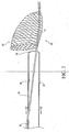
- Figure 4 illustrates distal embolic protection device filter 70, with delivery catheter 24 being proximally retracted as indicated by directional arrows 84.
- catheter distal end 40 has been fully retracted from the patient, distal embolic protection device shaft 74 is exposed, as indicated at 86, and can be grasped by the treating physician, leaving only a length between catheter distal end 40 and catheter proximal sidewall port 50 unavailable for grasping:
- distal embolic protection device shaft 74 grasped at 86 delivery catheter 24 can be fully retracted from device shaft 74.
- only the added length between catheter distal end 40 and catheter proximal sidewall port 50 need be added to distal embolic protection device shaft 74, rather than doubling its length.
- Figure 4A illustrates one delivery catheter 100 having a distal end or tip 102, a distal region 104 and a lumen 106 extending therethrough.
- Delivery catheter 100 further has a collapsible tube 108 disposed within catheter lumen 106.
- Collapsible tube 108 can serve as collapsible guide wire tube extending between catheter distal end 102 and distal sidewall port 48.
- Collapsible tube 108 includes a distal end 112 and a lumen 114 extending therethrough.
- Collapsible tube 108 preferably extends distally of the delivery catheter distal end and may be of a contrasting color to facilitate identification of the collapsible tube distinct from the delivery catheter.
- Tube 108 further includes a proximal region 116 which can be bonded to the catheter sidewall near distal sidewall port 48 to provide an exit for the guide wire.
- Distal sidewall port 48 preferably has a skived configuration.
- FIG. 4B illustrates delivery catheter 100 in an end view.
- Delivery catheter 100 has collapsible tube 108 within.
- Collapsible tube 108 is shown in the open position, having guide wire 19 extending therethrough.
- Collapsible tube at 108 has a tube wall outer surface 118 facing a catheter tubular wall inner surface 120.
- Collapsible tube outer surface 118 can be bonded to catheter wall inner surface 120.
- Suitable bonding methods including adhesives, and heat and solvent welding may also be used to attach collapsible tube 108 to catheter 120.
- Longitudinal stiffening members 115 may be included in the collapsible wall.
- Guide wire 19 may be seen extending through collapsible tube lumen 114.
- Guide wire 19 may extend proximally through the tube and out distal sidewall port 48.
- Collapsible tube 108 preferably has sufficient column strength to guide a back loaded guide wire, while being radially weak to collapse and allow passage of a filter.
- the proximal end of guide wire 19 can be inserted into collapsible tube distal end 112, and pushed proximally until the guide wire proximal end extends through distal sidewall port 48. Collapsible tube 108 thus aids in back loading guide wire 19 through delivery catheter 100.
- Figure 4C illustrates delivery catheter 100 having guide wire 19 retracted from collapsible tube 108.
- Collapsible tube 108 is shown in its collapsed position.
- Distal embolic protection device filter 70 has been forced distally forward from its parked position proximal of distal sidewall port 48.
- Distal embolic protection device filter 70 has thus forced part of collapsible tube 108 aside, collapsing the collapsible tube.
- Distal embolic protection device filter 70 may then be distally advanced from the delivery catheter.
- Collapsible tube 108 may be made of any suitable, collapsible polymer, well known to those skilled in the art.
- collapsible tubes are formed of LDPE, while other collapsible tubes are formed of PEBAX, nylon, or polyurethane.
- the collapsible tube is formed of elastomeric polymer such as polyurethane, silicone, latex, and the like.
- FIG. 4D illustrates another delivery catheter, catheter 130.
- Delivery catheter 130 includes a distal end port 131, a sidewall 134, and a distal sidewall port 148.
- Delivery catheter 130 has a hinged flap 132.
- Hinged flap 132 can be fixedly secured to catheter sidewall 134 just proximal of distal sidewall port 148, as indicated at 136.
- the hinged flap can be a round flap having a tab for bonding to the sidewall, and any suitable bonding method, for example, solvent welding, adhesive, or heat bonding can be used to affix flap 132 to sidewall 134.
- Sidewall port 148 can also be skived to ease in threading a guide wire through the port.
- Flap 132 includes a central portion 138 and an extreme end portion 140 which is opposite of bonded portion 136. As indicated by arrow 135, hinged baffle or flap 132 can be forced aside by an advancing distal embolic protection device filter. In the position shown in Figure 4D , a guide wire can be inserted through catheter distal end port 131 until encountering flap 132. The guide wire proximal end will then be forced along flap 132 and guided to sidewall port 148. Hinged baffle or flap 132 thus aids in back loading a guide wire through a catheter distal end port and out through the distal sidewall port.
- the hinged baffle or flap 132 can be formed of any suitable material. Exemplary materials include HDPE, PEBAX, nylon, polyimide, PEEK, or liquid crystal polymer.
- Figure 5A illustrates another distal embolic protection device delivery assembly 180 including another embodiment of delivery catheter in a three-port delivery catheter 182, having guide wire 19 disposed partially within, having distal embolic protection device 26 also disposed partially within, and being disposed within guide catheter 22.
- Guide wire 19, distal embolic protection device 26, and guide catheter 22 are as previously described with respect to Figure 1 .
- Delivery catheter 182 may be seen to have a distal end 184 having a distal end port 186 disposed therein. Delivery catheter 182 further has a distal region 188, a proximal region 190, a proximal end 192, and a lumen 194 extending therethrough.
- catheter 182 may be formed of a shaft in the proximal region 190.
- Delivery catheter 182 may be seen to include a distally tapering outer diameter over distal region 188.
- the distally tapering region can act to more closely approach guide wire 19, and provide support for the guide wire.
- the distal taper can also act to decrease any gap between guide wire 19 and the inner wall of catheter distal end 184.
- distal end port 41 is large enough to pass the filter.
- distal end port 186 need only be large enough to pass a guide wire, for example a 0.014 inch (0.036 cm) O.D. guide wire.
- the smaller profile of delivery catheter distal end 184 can significantly reduce the likelihood of catheter 182 snagging or hanging up on a stent or on a stenosed vessel region to be crossed.
- Delivery catheter distal region 188 also includes a distal sidewall port 189 for admitting a distal embolic protection device filter therethrough.
- distal sidewall port 189 has a round or oblong or oval shape.
- distal sidewall port 189 is formed as a slit or slot which can expand to allow passage of an advancing distal embolic protection device filter therethrough.
- distal sidewall port 189 is formed as a slit having a strain relief hole at either end.
- Delivery catheter 182 also includes a proximal sidewall port 200.
- Proximal sidewall port 200 can be dimensioned to allow passage of distal embolic protection device shaft 74.
- proximal sidewall port 200 is also large enough to admit passage of filter 70.
- Port 200 can be skived and dimensioned to receive a guide wire at a shallow entry angle, as previously discussed with respect to other sidewall ports.
- a flap or ramp region 202 is disposed just proximal of proximal sidewall port 200.
- Ramp or flap 202 can act to guide a back loaded distal embolic protection device shaft proximal end through proximal sidewall port 200 as the shaft is advanced proximally through delivery catheter 182, being forced or guided to exit the catheter lumen 194 through proximal sidewall port 200.
- Ramp or flap 202 need not be hinged, and can be fixed, in embodiments where a continuous lumen through the delivery catheter is not required.
- catheter 182 can be formed as a shaft proximal of proximal sidewall port 200.
- FIGS 5A and 5B illustrate one embodiment of delivery catheter sidewall port 200 having ramp 202 formed by making a slit 205 through the tube wall of the catheter, then collapsing the tube wall to form ramp 202, just proximal of proximal sidewall port 200.
- the collapsed tubular wall can be held in place through any suitable adhesive or bonding method.
- the collapsed tube wall thus forms a ramp, which can be used to guide a back loaded distal embolic protection device shaft through proximal sidewall port 200.
- the lumen can be filled by a solid cylinder with a bias cut end and the cylinder bonded in place.
- delivery catheter 182 also includes an intermediate sidewall port 206, disposed between distal sidewall port 189 and proximal sidewall port 200.
- distal sidewall port 189 can be disposed on the opposite side of delivery catheter 182 from proximal sidewall port 200.
- Proximal sidewall port 200 can thus be located 180° away from distal sidewall port 189.
- intermediate sidewall port 206 is substantially aligned with distal sidewall port 189.
- Intermediate sidewall port 206 can be dimensioned to receive guide wire 19 therethrough.
- intermediate sidewall port 206 is skived, as previously discussed with respect to other wire admitting sidewall ports
- distal sidewall port 189 is located between about 0.2 and 5.0 cm from catheter distal end 184.
- Intermediate sidewall port 206 cay be located between about 5 and 30 cm from distal end 184.
- Proximal sidewall port 200 can be located between about 15 and 50 cm from catheter distal end 184.
- distal sidewall port 189 and proximal sidewall port 200 are disposed between about 5 and 20 cm apart.
- assembly 180 can be similar in many respects to assembly 20, discussed with respect to Figure 1 .
- Guide wire 19 can be advanced through guide catheter 22 to the target site, as previously discussed.
- Guide wire 19 can be threaded through catheter distal end port 186, exiting the delivery catheter through intermediate sidewall port 206, then running along the exterior of the delivery catheter to beyond the catheter proximal end.
- guide wire 19 is front loaded through delivery catheter 182 by forcing guide wire distal tip 60 distally through intermediate sidewall port 206 then out delivery catheter distal end port 186.
- the catheter can thus be threaded over the guide wire but remain outside of the patient until the combination is jointly advanced to a region of interest.
- Distal embolic protection device 26 can have the proximal end of distal embolic protection device shaft or wire 74 proximally back loaded through distal sidewall port 189, with distal embolic protection device filter 70 in a compact configuration and pulled proximally toward proximal sidewall port 200.
- distal embolic protection device filter 70 is advanced or front loaded through proximal sidewall port 200 to the "parked" position between proximal sidewall port 200 and intermediate sidewall port 206.
- Guide catheter 22 can be advanced to a coronary ostium, or other location.
- Guide wire 19 can then be advanced through the guide catheter and further to a target site to be protected.
- the guide wire proximal end can be threaded through catheter distal end port 186 and out intermediate sidewall port 206.
- Delivery catheter 182, carrying distal embolic protection device 26, can be advanced over guide wire 19 distally from guide catheter 22 and beyond the site to be protected. With delivery catheter 182 and carried distal embolic protection device 26 in position, guide wire 19 can be proximally retracted, as previously discussed.
- Figure 6 illustrates delivery catheter 182, after guide wire 19 has been proximally retracted through intermediate port 206.
- Distal embolic protection device 26 can be distally advanced through distal sidewall port 189, thus exiting delivery catheter 182.
- delivery catheter 182 is proximally retracted, while maintaining the position of distal embolic protection device filter 70. With distal embolic protection device filter 70 in position, and suitably expanded to filter particulates, delivery catheter 182 can be proximally retracted over distal embolic protection device shaft or wire 76. As may be seen from inspection of Figure 6 , only the length of distal embolic protection device shaft 76 between proximal sidewall port 200 and distal sidewall port 189 is disposed within delivery catheter 182.
- a suitable ramp or bump within delivery catheter 182 can further guide distal embolic protection device filter 70 through distal sidewall port 189.
- a hinged flap or baffle similar in some respects, but not others, to the hinged baffle described with respect to Figure 4 can be used. In this embodiment, the hinged baffle can allow proximal movement of a back loaded guide wire through distal end port 186 while resisting distal movement of distal embolic protection device 70 against the flap.
- the distal embolic protection device has no long distal tip, for example, no 0.014 inch (0.036 cm) O.D. wire tip, as the tip may try to exit distal end port 186.
- the guide wire is left within distal end port 186, in order to prevent the filter body from attempting to exit the distal end port.
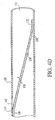
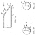
- Figure 7A illustrates one embodiment of delivery catheter 220 having a distal region 226 which is asymmetric, having a substantially straight portion 228 and a tapering portion 230.
- Tapering portion 230 has a distal sidewall port, slit or slot 232 therethrough.
- a distal end port 222 is disposed within distal end 224 of delivery catheter 220.
- distal end port 222 is dimensioned to accept a guide wire therethrough, but not a distal embolic protection device filter. This can act to prevent unwanted attempted or partial distal passage of a distal embolic protection device filter through distal end port 222.
- Distal end port 222 is preferably located off-center from the central longitudinal axis of the delivery catheter 220.
- slit 232 is located to be axially aligned with the longitudinal central axis of the delivery catheter 220.
- Figure 7B illustrates delivery catheter 220, viewed from the distal end.
- the off-center location of distal end port 222 and the downwardly slanting orientation of distal sidewall port 232 toward distal end port 222 may also be seen.
- Distal sidewall port 232 may also be described as being accessible from the delivery catheter distal end when approached along the central longitudinal axis through the catheter, either from within the catheter or from the distal end of the catheter.
- the orientation of distal sidewall port 232 can allow a distal embolic protection device filter to be more easily distally forced from catheter 222 and out distal sidewall port 232.
- FIG. 7C illustrates another embodiment of delivery catheter in catheter 240.
- Delivery catheter 240 is similar in some respects to delivery catheter 220, discussed with respect to Figures 7A and 7B .
- Delivery catheter 240 includes a "tearable" distal sidewall port 242 and a distal end port 244.
- Distal sidewall port 242 can be formed as a region of preferential tearing or weakness.
- the preferential tearing can be formed by perforating the sidewall of the catheter or cutting partially through the sidewall of the catheter, such that a distal embolic protection device being advanced distally against the region of preferential tearing can be forced through the preferential tearing region and out of the delivery catheter.
- the preferential weakness of the distal sidewall port and/or the distal end port can be formed by making the catheter with an extremely thin wall in the regions to be torn.
- FIG. 8 illustrates another embodiment of the present invention, in a "slotted" delivery catheter.
- Slotted delivery catheter 300 may be seen to include a distal end 302, a distal end port 304, a distal region 306, a proximal region 308, and a lumen 303.
- Slotted delivery catheter 300 can include a slot 310 extending over a substantial portion of the length of the catheter, and can have a distal unslotted region 311 which can provide column strength.
- Slot 310 preferably has a width of at least about 0.001 inch (0.0025 cm).
- Slot 310 is preferably dimensioned to significantly inhibit the passage of a guide wire, for example a 0.014 inch (0.036 cm) outside diameter guide wire, through the slot.
- Slot 310 preferably has a widened distal region or sidewall port 312 dimensioned to freely admit passage of a guide wire therethrough.
- distal sidewall port 312 is dimensioned to be about 0.002 inch (0.0051 cm) larger than the outside diameter of the guide wire to be used in conjunction with the delivery catheter, or, in the example given, 0.016 inch (0.041 cm) in width.
- Port 312 can be skived to provide a shallow entry angle, as previously discussed with respect to other ports.
- Slot 310 continues to a slot proximal end 316.
- slot 310 extends to a proximal end port 318 which is longitudinally accessible from the proximal end of the catheter.
- Proximal region 308 can include an offset handle 312, shown schematically in Figure 8 .
- Proximal end port 318 is large enough to admit the wire or shaft of a distal embolic protection device therethrough.
- Delivery catheter 300 preferably has a tube wall 322 sufficiently stiff to inhibit the unwanted transverse or radial movement of a wire or shaft through the slot, yet sufficiently resilient to allow a wire or shaft to be forced through the slot, upon the application of sufficient force or pressure, as would not be encountered in use within the human body.
- Delivery catheter 300 can be formed of polymers well known to those skilled in the art, for example, PEBAX, nylon, PET, Polyimide or HDPE.
- Slot 310 is preferably between about 0.001 and 0.032 inch (0.0025 cm to 0.081 cm) in width, more preferably between about 0.001 and 0.010 inch (0.0025 cm to 0.025 cm) in width.
- slot 310 is about 0.001, 0.005, 0.007, 0.009 and 0.010 inch (0.0025, 0.0127, 0.0178, 0.0228, and 0.025 cni, respectively) in width and distal sidewall port 312 is at least about 0.016 inch (0.041 cm) in width.
- slot dimensions can be adjusted accordingly.
- Slot 310 may be seen to terminate distally at distal sidewall port 312.
- unslotted portion 311 between slot sidewall port 312 and catheter distal end 302 is between about 5 and 30 cm, preferably being at least about 5 cm, more preferably being at least about 2 cm in length.
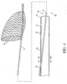
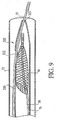
- Figure 9 illustrates delivery catheter 300, in use within guide catheter 22, disposed over guide wire 19, and carrying distal embolic protection device 26 within.
- guide wire 19 lies within lumen 303 of delivery catheter 300 and extends proximally through lumen 303, exiting delivery catheter 300 through distal sidewall port 312.
- Distal embolic protection device shaft of wire 76 may be seen to lie within lumen 303.
- Guide wire 19, delivery catheter 300, and distal embolic protection device 26 can be advanced to a target site, substantially as previously described with respect to other embodiments.
- Guide wire 19 can extend proximally outside of delivery catheter 300, exiting proximally near the point of entry into the patient.
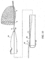
- Figure 10 illustrates distal embolic protection device'26, having distal embolic protection device distal filter 70 being held in position while delivery catheter 300 is proximally retracted, thereby forcing filter 70 from catheter distal end port 304.
- Guide wire 19 had previously been proximally withdrawn through distal sidewall port 312, as previously described with respect to other embodiments.
- Figure 10 further illustrates slot 310 in proximal region 308, having guide wire 19 being forced transversely through slot 310, thereby forcibly widening the slot width to allow exit of wire 76 through slot 310.
- the proximal end of distal embolic protection device shaft or wire 76 can be held as indicated at 330 by the treating physician while proximally retracting the delivery catheter as indicated at 332.
- distal embolic protection device shaft or wire is maintained in a substantially constant position while removing the slotted delivery catheter over the constant position distal embolic protection device shaft or wire 76.
- delivery catheter 300 is proximally retracted until the shaft or wire 76 reaches distal sidewall port 312. At this point, the delivery catheter can be further proximally retracted to expose the distal embolic protection device shaft distally extending from distal end port 304 of catheter 300.
- the exposed shaft 76 can be grasped, and the delivery catheter fully retracted from over the end of the distal embolic protection device shaft or wire 76.
- the added length to the distal embolic protection device shaft or wire required to allow removal of the delivery catheter over the shaft may be seen to be only the distance between the distal end port 304 and distal sidewall port 312, rather than double the length of the shaft.
Landscapes
- Health & Medical Sciences (AREA)
- Cardiology (AREA)
- Oral & Maxillofacial Surgery (AREA)
- Transplantation (AREA)
- Engineering & Computer Science (AREA)
- Biomedical Technology (AREA)
- Heart & Thoracic Surgery (AREA)
- Vascular Medicine (AREA)
- Life Sciences & Earth Sciences (AREA)
- Animal Behavior & Ethology (AREA)
- General Health & Medical Sciences (AREA)
- Public Health (AREA)
- Veterinary Medicine (AREA)
- Surgical Instruments (AREA)
Description
- The present invention is related generally to intravascular medical devices. More specifically, the present invention is related to delivery and recovery catheters which can be used to deliver and recover embolic protection devices, including distal embolic protection filters.
- Coronary vessels, partially occluded by plaque, may become totally occluded by a thrombus or blood clot causing myocardial infarction, angina and other conditions. A number of medical procedures have been developed to allow for the removal of plaque from vessel walls or to clear a channel through the thrombus or clot to restore blood flow and minimize the risk of myocardial infarction. Carotid, renal, peripheral, and other blood vessels can also be blocked and require treatment. For example, atherectomy or thrombectomy devices can be used to remove atheroma or thrombus. Alternatively, in percutaneous transluminal coronary angioplasty (PTCA), a guide wire and guide catheter are inserted into the femoral artery of a patient near the groin, advanced through the artery, over the aorta, and into a coronary artery. An inflatable balloon is then advanced into the coronary artery, across a stenosis or blockage, and the balloon inflated to dilate the blockage and open a flow channel through the partially blocked vessel region. One or more stents may also be placed across the dilated region or regions. While some stenoses remain in place once dilated and/or stented, others are more brittle, and may partially crack and fragment after the dilation or stent placement, allowing the fragments to flow downstream where they may block more distal and smaller coronary vessels, possibly causing myocardial infarction, from that site. Consequences of embolization include stroke, diminished renal function, and impairment of peripheral circulation possibly leading to pain and imputation.
- Saphenous vein grafts are often used to bypass occluded coronary vessels in coronary artery bypass surgery. With time, the grafts can become occluded with grumous. The grumous can also be dilated with balloons or removed in other ways. The grumous can present an even more difficult material to remove than thrombus, as the material is very friable, and likely to break into smaller fragments during the removal procedure.
- Distal embolic protection devices have been developed to prevent the downstream travel of materials such as thrombi, grumous, emboli, and plaque fragments. Devices include occlusive devices and filters. Occlusive devices, for example distal inflatable balloon devices, can totally block fluid flow through the vessel. The material trapped by the inflatable devices can remain in place until removed using a method such as aspiration. However, aspiration cannot remove large particles because they won't fit through the aspiration lumen. Also, aspiration is a weak acting force and won't remove a particle unless the tip of the aspirating catheter is very close to the particle to be removed. During the occlusion, the lack of fluid flow can be deleterious. In coronary applications, the lack of perfusing blood flow can cause angina. In carotids, seizure can result from transient blockage of blood flow. In both coronaries and carotids it is not possible to predict who will suffer from angina or seizure due to vessel occlusion. If a procedure is started with an occlusive device, it may be necessary to remove it and start over with a filter device.
- Some distal embolic protection devices include filters. Filters can allow perfusing blood flow during the emboli capture process. The filters-can be advanced downstream of a site to be treated and expanded to increase the filter area. Emboli, such as grumous or atheroma fragments, can be captured in the filter until the procedure is complete or the filter is occluded. When the capacity of the filter is reached, the filter may then be retracted and replaced.
- Distal embolic protection devices can be delivered over guide wires and within guide catheters. The distal embolic protection methods are normally practiced ancillary to another medical procedure, for example PTCA with stenting or atherectomy. The distal embolic protection procedure typically protects downstream regions from emboli resulting from practicing the therapeutic interventional procedure. In the example of PTCA, the treating physician must advance a guide wire over the aorta and into a coronary ostium. Advancing the guide wire through tortuous vessels from a femoral artery approach can be difficult, and vary with both the patient and the vessel site to be treated. Guide wires are typically selected by the treating physician, based on facts specific to the patient and therapeutic situation, and also on the training, experiences, and preferences of the physician. In particular, a physician may have become very efficient in using a specific guide wire to identify the left coronary ostium and then advance a balloon catheter over the positioned guide wire. The efficacy of the procedure may depend on the physician being able to use their favored guide wire.
- The distal embolic protection device is preferably delivered using the same, favored guide wire. The phrases "distal embolic protection device" or "emboli protection device" are used herein to refer to embolic protection devices that are occlusive and/or filtering. The terms "distal embolic protection device" and "embolic protection device" are used interchangeably, as either may be used to protect a target site located either proximal to or distal to another treatment site. The term "embolic protection element" may be used generally to include both occlusive and filtering elements disposed near the distal region of a distal protection device shaft.
- In the example PTCA procedure, a guide catheter extends proximally from the patient's groin area, and may be about 100 centimeters (cm) long, later having a 140 cm long guide wire proximal region extending from the guide catheter. The distal embolic protection device delivery catheter, nominally about 130 cm in length, can be advanced over the guide wire and within the guide catheter, until a short length of guide wire extends from both the guide catheter and delivery catheter. The guide wire can then be retracted and removed from the patient. In some methods, the distal protection device is then advanced through and out of the positioned delivery catheter, to the target site to be protected or filtered. In other methods, delivery is accomplished by disposing the distal embolic protection filter device within the delivery catheter distal region, and advancing the delivery catheter and embolic protection device together over the guide wire, and deploying the filter by retracting the delivery catheter while maintaining the position of the filter, thus forcing the filter distally out of the delivery catheter.
- Advancement of the delivery catheter over a single length, nominally 130 cm long guide wire presents a problem. The treating physician can only advance the filter delivery catheter about 20 cm over the guide wire until the delivery catheter advances into the patient and the guide wire is inaccessible within the delivery catheter. The guide wire position should be controlled at all times so as to not be dislodged by the advancing delivery catheter from the hard acquired guide wire position within the patient.
- One solution to this problem is to use a guide wire at least double the length of the delivery catheter. A 320 or 340 cm long guide wire can extend at least about 120 cm from the patient's groin, having an accessible region exposed at all phases of delivery catheter placement. However, the added length makes manipulating and rotating the guide wire very difficult for the treating physician. The extra length of the guide wire can be held by additional personnel to prevent the added wire length from falling to the floor, where it would become contaminated. However, not all cardiac catheter laboratories have personnel available to maintain control of the long guide wire. In many labs, the physician is working alone in the sterile field.
- Advancing a distal embolic protection device delivery catheter over a positioned, favored guide wire would be inherently more efficacious than requiring use of an unfamiliar, disfavored, or double length guide wire to position the delivery catheter.
- With the distal filter in place, removal of the delivery catheter over the wire shaft of the distal filter device is ultimately desirable. If a single length, nominally 140 cm long, distal filter device shaft is extending about 20 cm proximally from the delivery catheter, a problem is presented. Once the delivery catheter is retracted about 20 cm, the proximal end of the wire would disappear into the proximal end of the retracting delivery catheter, and control of the distal filter device wire position lost. If the delivery catheter were further retracted, the retraction of the delivery catheter over the wire shaft may pull the distal filter device from its position. Again, a distal protection device having a double length wire shaft can be used. The double length wire shaft allows the delivery catheter to be retracted over the distal filter device shaft while presenting an exposed portion of the wire shaft at all times. As discussed with respect to the double length guide wire, the added length presents problems.
WO02/28292 - What would be desirable are distal embolic protection device delivery catheters that can be delivered over the single length guide wire favored by the treating physician and retracted over single length wire shafts of distal embolic devices.
- Insofar as the terms "invention" and/or "embodiment" are used in the following, and/or features are presented as being optional, this should be interpreted in such a way that the only protection sought is that of the invention as claimed.
- The present invention provides improved delivery catheters which can be used to deliver and recover embolic protection devices, including distal embolic filter devices. The catheters are "rapid exchange "or" single operator exchange" catheters that can be delivered over a single length guide wire. The catheters can also be retracted over a single length distal embolic filter device wire shaft. Catheter assemblies and methods for using the assemblies are also provided.
- A first catheter according to the invention is a two port catheter having two sidewall ports for receiving wires through the ports. One two port catheter incudes a distal region, an intermediate region, and a proximal region for extending out of the patient's body. Some two port catheters include a tubular body having a tube sidewall and a lumen extending through the tube. The two port catheter can be formed of a tube over its entire length or be tubular only in the distal region, being formed of a shaft in the intermediate and proximal regions. The distal region can include a distal end port or distal tip port, a distal sidewall port, and a proximal sidewall port. The distal end port and the distal sidewall port can be dimensioned to allow passage of a guide wire. The proximal sidewall port can be dimensioned to allow passage of an embolic protection device wire shaft through the port. In a preferred embodiment, the distal end port, the distal sidewall port, and the proximal sidewall port are all dimensioned to allow passage of a 0.014 inch (0.035 cm) outside diameter wire through the ports. The catheter inside diameter can be dimensioned to allow passage of an embolic filter in a compressed state. Some catheters are formed of a tube extending from the distal end to the proximal end, while other catheters are formed of a tube in the distal region and a shaft or smaller tube in the intermediate and proximal regions. The present invention also includes catheter assemblies which can include a two port catheter, a guide wire, a distal embolic protection device, and a guide catheter adapted to receive the catheter within.
- In use, a guide catheter can be advanced through the vasculature to a location near the ultimate target site to be filtered. A guide wire can be advanced through the guide catheter and further to a location nearer the target site or even distally past the target site.
- A distal embolic protection device, for example, a distal embolic protection filter device having a distal filter element and elongate wire shaft, can be provided. The filter device can be disposed within the two port catheter such that the distal filter element lies between the distal sidewall port and the proximal sidewall port, with the wire shaft extending outwardly through the proximal sidewall port to extend proximally along the length of the catheter. In one method, the distal filter element is radially reduced in shape and advanced distally into the catheter through the proximal sidewall port. In a preferred method, the distal embolic protection device is back loaded into the catheter by threading the distal embolic protection device shaft proximal end into the catheter distal end port and out of the catheter proximal sidewall port. In some embodiments, the distal filter element lies within a bulge between the distal sidewall port and the proximal sidewall port.
- The guide wire proximal end can be threaded into the catheter distal end port and out of the catheter distal sidewall port to extend proximally along the exterior of the catheter. The catheter carrying the distal embolic protection device can then be advanced distally over the guide wire to near the target site. In one method, the catheter is advanced across the target region while in other methods the catheter is advanced to a position proximal of the target region. The guide wire can then be proximally retracted, and pulled from within the catheter through the distal sidewall port. The distal filter element is then advanced distally out of the two port catheter distal end port and allowed to expand in some methods. In other methods, the distal filter element is held in a relatively constant position, while the catheter is retracted proximally away from the distal filter element, such that the distal filter element exits the catheter distal end port and is allowed to radially expand to filter blood in the vicinity of the target site.
- When deemed desirable by the treating physician, the catheter can be proximally retracted from the patient by grasping the proximal end of the distal embolic protection device shaft while proximally retracting the catheter. As only a short length of the distal embolic protection device wire shaft extends through the catheter distal region, only a short added length of wire shaft is required, rather than a double length wire shaft as would be required by a conventional catheter. In some methods, the back loading of the guide wire through the distal end port and out of the distal sidewall port is aided by a collapsible guide wire tube extending from near the distal end port to the distal sidewall port. In other embodiments, the back loading of the guide wire is aided by a hinged flap or baffle which allows a distally advancing filter element to move the flap aside but which does not allow a proximally advancing guide wire to pass, rather directing the guide wire proximal movement outward towards the distal sidewall port.
- After the therapeutic procedure the catheter may be used to recover the embolic protection device. To do so the proximal end of the embolic protection device shaft proximal end is threaded into the distal end port and out the proximal sidewall port. The catheter is advanced into the patient along the device shaft until the catheter tip is immediately proximal to the embolic protection device. At this point the embolic protection device may be partially or totally recovered into the lumen of the catheter by effecting relative motion between the device shaft and the catheter. Subsequently the catheter/embolic protection device can be withdrawn as a unit from patient's body.
- Another catheter according to the present invention is a three port catheter, having three sidewall ports. The three port catheter can be formed of a tube over its entire length or be tubular only in the distal region, being formed of a shaft in the intermediate and proximal regions. The three port catheter can include a distal end port dimensioned to allow passage of a guide wire through the port, but not being large enough to allow passage of a filter element. The reduced size of the distal end port allows for a reduced profile catheter distal end, which can now be narrowly tapered to allow passage through smaller diameter vessels and past more highly stenosed vessel regions. The distal end port can also be tapered to perfectly match the guide wire so as to facilitate smooth passage across vessel irregularities such as calcium spicules or implanted stents. The three port catheter can include a distal sidewall port, an intermediate sidewall port, and a proximal sidewall port. The intermediate sidewall port can be dimensioned to allow passage of a guide wire through the port, and can function in a similar manner to the distal sidewall port described with respect to the two port catheter. In some catheters, the intermediate port is substantially circumferentially aligned with the distal sidewall port.
- The proximal sidewall port in the three port catheter can be disposed opposite the distal sidewall port, and can be about 180° opposite the distal sidewall port. In other respects, the proximal sidewall port can serve the same function as the proximal sidewall port discussed with respect to the two port catheter. Specifically, the proximal sidewall port can allow passage of the distal embolic protection device wire shaft through the port. The distal sidewall port of the three port catheter can serve to allow passage of the distal embolic protection device filter through the distal sidewall port. The distal sidewall port can be a slit in some embodiments, a slot in other embodiments, and a round or oval opening in still other embodiments. The three port catheter is designed such that the distal embolic protection device filter element can be carried between the intermediate sidewall port and the proximal sidewall port, then forced distally through the distal sidewall port rather than through the distal end port as in the two port catheter. The distal sidewall port can thus be a slit which is forced open by the advancement of the filter element. Thus, only the distal sidewall port need be sufficiently large to allow passage of the filter, rather than the distal end port. In some three port catheters, the distal end port is disposed off center from the central longitudinal axis of the catheter while the distal sidewall port is substantially aligned with the central longitudinal axis of the catheter such that distal advancement of the filter element is directed substantially toward the distal sidewall port rather than the distal end port.
- In use, the guide catheter and guide wire can be advanced to near the target site, as with the two port catheter. The distal embolic protection device can be back loaded through the distal sidewall port, with the wire shaft of the distal embolic protection device exiting the proximal sidewall port, leaving the filter element disposed within the catheter, preferably between the proximal sidewall port and the intermediate sidewall port. The guide wire proximal end can be threaded through the distal end port of the catheter to exit the intermediate port of the catheter. The preloaded catheter can be advanced to near the target site. In some methods, the guide wire is left in place after catheter placement to preclude the possibility of the filter element being forced into the distal end port. The filter element may also be provided without a wire tip to address the same problem. In a preferred method, the guide wire is retracted and the embolic protection filter body advanced distally out of the distal sidewall port. With the distal embolic protection device in position, the catheter can be proximally retracted from the patient. The distal embolic protection device wire shaft need only be slightly longer than the catheter, not twice as long, as only a short length of distal embolic protection device wire shaft lies within the distal region of the catheter.
- After the therapeutic procedure the three port catheter can be used to recover the embolic protection device by threading the proximal end of the device shaft into the distal sidewall port, out the proximal or intermediate port, and proceeding as described for the two port catheter.
- A third catheter according to the present invention includes a tube having a normally open slot extending along most of the tube length. The slotted catheter preferably has a distal end port dimensioned to allow passage of a guide wire and a distal embolic protection device filter through the port. The catheter preferably has a distal sidewall port to allow passage of a guide wire through the distal sidewall port. The distal sidewall port can, but need not, be formed as a widened or enlarged portion of the longitudinal slot extending through the sidewall. The catheter preferably has an unslotted distal most region to provide column strength for allowing the catheter to be pushed across narrowed, stenosed vessel regions. Some catheters include a funnel portion disposed near the proximal region to aid in introducing the distal embolic protection device filter into the lumen within the catheter.
- The slot is preferably at least about 0.001 inch (0.0025 cm) in width, and can be about 0.005 inch (0.0027 cm) or even 0.014 inch (0.035 cm) in width. The slot is preferably dimensioned to inhibit the free, transverse movement of a guide wire or distal embolic protection device wire shaft through the slot. The catheter body is preferably sufficiently resilient to allow the forced, transverse movement of a wire shaft or guide wire through the slot when such movement is desired. The distal-most tip can be located off center, with the center of the distal profile being occupied by the slot. The distal-most sidewall region can be curved or bent down to form an end wall containing the off-center, distal-most tip.
- In use, a guide catheter can be advanced to near the target site, followed by the advancement of a guide wire, as with the two and three port catheters previously discussed. The guide wire proximal end can be threaded into the distal end port and out of the distal sidewall port, to extend along the outside of the catheter. The distal embolic protection device can be preloaded into the distal region of the slotted catheter. In some embodiments, the distal embolic protection device is front loaded by distally advancing the device into the proximal end of the catheter and further into the catheter distal region. In other methods, the distal embolic protection device is back loaded by proximally threading the distal embolic protection device wire shaft through the catheter distal end port and further proximally through the catheter until the wire shaft exits the proximal end of the catheter, and the filter element is disposed proximal of the distal sidewall port of the catheter.
- The catheter carrying the distal embolic protection device can then be advanced over the guide wire to near the target site or across the stenosis. The guide wire can be proximally retracted from the catheter, followed by the deployment of the filter element through the catheter distal end port. When removal of the catheter is desired, the distal embolic protection device wire shaft can be forced transversely through the slot in the catheter beginning near the catheter proximal end. The wire shaft can be held substantially stationary, while the catheter is proximally retracted from the patient. The proximal retraction can be continued until the wire shaft is disposed within the distal sidewall port of the slot, whereupon the wire shaft can be grasped distal of the catheter distal end port and the catheter fully removed from the patient.
- In a related method using the slotted catheter, the catheter can be advanced to across the stenosis or near the target site over the guide wire, with the catheter not yet carrying the distal embolic protection device. The distal embolic protection device can later be advanced through the lumen of the slotted catheter to the catheter distal region. The catheter can also be used to recover an embolic protection device as described for the two port catheter.
-
-
Figure 1 is a highly diagrammatic, cut-away, side view of an assembly for delivering or recovering a distal embolic protection device, including a two-port catheter having a distal end port, a distal sidewall port, a proximal sidewall port, and having a guide wire disposed through the distal sidewall port, and a distal embolic protection device wire shaft extending through the proximal sidewall port, the catheter being disposed within a guide catheter; -
Figure 2 is a highly diagrammatic, cutaway side view of the assembly ofFigure 1 , after the catheter has been advanced distally from the guide catheter, and the guide wire advanced distally from the catheter; -
Figure 3 is a fragmentary, side view of the catheter ofFigure 2 , after the guide wire has been proximally retracted from the catheter and the catheter proximally retracted to expose the distal embolic protection device filter; -
Figure 4 is a fragmentary side view of the distal embolic protection device and catheter ofFigure 3 , with the catheter being retracted over the distal embolic protection device wire shaft; -
Figure 4A is a fragmentary, side view of a catheter having a collapsible guide wire tube extending between the catheter distal end and the distal sidewall port; -
Figure 4B is an end view of the catheter ofFigure 4A , having a guide wire disposed within the collapsible guide wire tube; -
Figure 4C is an end view of the catheter ofFigure 4A , having the guide wire removed and the collapsible guide wire tube collapsed by the advancement of a distal embolic protection device filter; -
Figure 4D is a fragmentary, side view of another catheter having a hinged baffle for directing a proximally back loading guide wire through the distal sidewall port while moving aside to allow distal passage of a distal embolic protection device filter; -
Figure 5A is a fragmentary, cut-away, side view of a guide catheter, guide wire, and distal embolic protection device as inFigure 1 , including a three-port catheter having a distal sidewall port for admitting a distal embolic protection device filter, a intermediate sidewall port for admitting a guide wire, and a proximal sidewall port for admitting a distal embolic protection device shaft or wire; -
Figure 5B is a detailed view fromFigure 5 , having a collapsed tubular wall or ramp portion to direct a back loaded distal embolic protection device wire shaft through the proximal sidewall port; -
Figure 6 is a fragmentary side view of the catheter ofFigure 5 , being advanced distally from the guide catheter, having the guide wire proximally retracted, and having the distal embolic protection device filter advanced distally through the distal sidewall port; -
Figure 7A is a fragmentary, longitudinal, wafer,view of one embodiment of three port catheter, similar in some respects to the catheter ofFigure 5 , having an off-center distal end guide wire port and an axially accessible distal end sidewall port for allowing passage of a distal embolic protection device filter; -
Figure 7B is an end view of the catheter ofFigure 7A ; -
Figure 7C is an end view of a catheter having regions of preferential tearing forming a distal sidewall port; -
Figure 8 is a fragmentary, highly diagrammatic, perspective view of a slotted catheter having a slot extending along substantially most of the catheter length, the slot being sufficiently narrow to inhibit unwanted transverse movement of a wire through the slot while being sufficiently resilient to allow forced transverse movement of a wire through the now expanded slot; -
Figure 9 is a side view of the catheter ofFigure 8 , carrying a distal embolic protection device, and being advanced within a guide catheter and over a guide wire; and -
Figure 10 is a fragmentary, side view of the catheter ofFigure 9 , being advanced distally from the guide catheter, having the guide wire proximally withdrawn, and the catheter proximally withdrawn from the deployed distal embolic protection device filter by forcing the distal embolic protection device wire or shaft through the slot. -
Figure 1 illustrates a distal embolicprotection device assembly 20 which can be used to deliver a distal embolic protection device to a target site within the vasculature.Assembly 20 includes a delivery/recovery catheter 24 disposed within aguide catheter 22. The delivery/recovery catheter can be used to both deliver and recover a distal embolic protection filter. The term "delivery catheter", as used herein, should be understood as including a delivery catheter that can also be used to recover a particulate containing filter.Delivery catheter 24 includes aguide wire 19 and a distalembolic protection device 26 disposed within. The proximal end ofassembly 20 is illustrated without any hub or Luer fitting to more clearly illustrate the invention. In a preferred embodiment, a hub, well known to those skilled in the art, can be affixed to the assembly proximal end to form a fluid-tight seal about the protruding members. Delivery catheters referred to in the present application preferably have no added therapeutic distal devices. Specifically, delivery catheters preferably are single lumen catheters and have no inflatable or expandable balloons, distal atherectomy burrs, water jet devices, or the like. Some delivery catheters can be coated with therapeutic coatings however, including anti-thrombogenic coatings, for example heparin, or with lubricious coatings, for example, hydrogels or silicone.. -
Guide catheter 22 includes adistal end 28, adistal region 32, aproximal region 34, aproximal end 36, and alumen 30 extending therethrough. Guide catheters are well known to those skilled in the art and will not be further explained.Delivery catheter 24 can be referred to as a "two-port" catheter, as it has two sidewall ports.Delivery catheter 24 includes adistal end 40, adistal region 42, a distal port ordistal sidewall port 48, a proximal port orproximal sidewall port 50, a proximal region 44, aproximal end 46, and alumen 38 extending therethrough. In some embodiments, proximal region 44 ofdelivery catheter 24 is formed by a shaft rather than a tube, withcatheter lumen 38 extending through only a distal region of the delivery device.Delivery catheter 24 also includes a distal end port or distal tip port 41, formed at the distal end of the catheter. In one embodiment, proximal region 44, which is proximal ofproximal port 50, can be formed by a tube which has been transversely slit and pressed downward proximal ofproximal port 50.Guide wire 19 may be seen to include adistal tip 60, adistal region 62, a wire orshaft 64, a proximal region 65, and aproximal end 66.Guide wire 19 may be seen to extend proximally fromdistal tip 60, withincatheter lumen 38, then extending outwardly throughdistal sidewall port 48 to extend proximally along the outside ofdelivery catheter 24. - Referring again to
Figure 1 , it may be seen thatguide wire 19 has been threaded through delivery catheterdistal sidewall port 48. In some methods,guide wire 19 is advanced throughguide catheter 22, with guide wireproximal end 66 yet to be threaded into delivery catheter distal end port 41 and out delivery catheterdistal sidewall port 48. In this methodproximal end 66 of the guide wire is threaded into distal end 41 of the catheter and out throughdistal sidewall port 48. This is referred to as "back loading". The wire back loading can be aided by arcing the distal region ofdelivery catheter 24, such that the guide wireproximal end 66 is pressed against the inner wall of the catheter neardistal sidewall port 48. In some embodiments, other assistance is given to back loading the guide wire into the delivery catheter and through the delivery catheter distal sidewall port. Distalembolic protection device 26 may be seen to include a shaft orwire 74 including adistal region 72 coupled to adistal filter 70. -
Distal filter 70 can be viewed as one type of distal emboli protection element. Other distal protection elements which can be included as part of the present invention are occlusive emboli protection elements, including expandable or inflatable elements for blocking fluid flow through a vessel. Unless otherwise indicated, occlusive elements should be considered as interchangeable with filter elements in the present invention. - Distal embolic
protection device shaft 74 may be seen to have aproximal region 76 and aproximal end 78 extending proximally fromguide catheter 22.Filter 70 is shown in a compressed, radially reduced profile configuration as a result of disposition withindelivery catheter 24. In a preferred embodiment,filter 70 is biased to expand radially outward when not constrained bydelivery catheter 24. Distal embolicprotection device filter 70 may be seen disposed betweenproximal sidewall port 50 anddistal sidewall port 48 inintermediate region 45. Distal embolicprotection device shaft 74 may be seen to lie withincatheter lumen 38 distal ofproximal port 50, then extend throughproximal port 50 to the exterior ofdelivery catheter 24, then extend along the outside ofdelivery catheter 24 over its length. - In one assembly,
guide wire 19 is formed of stainless steel or Nitinol and has a safety, spring tip.Guide wire 19 can have a length of between about 130 and 180 cm. in some embodiments.Guide wire 19 can have radiopaque marker bands along its length.Guide wire 19 may also have an outside diameter of between about 0.009 and 0.035 inch (0.023 to 0.089 cm) (in some embodiments, and about 0.014 inch (0.036 cm) in a commonly used embodiment.Delivery catheter 24 can be formed of materials well known to those skilled in the art. In one embodiment, the distal region ofcatheter 24 is formed of a softer, more pliable material than the more proximal regions of the catheter. In one embodiment, catheterdistal region 42 is formed of a rather floppy, soft material. In one catheter, the distal region is formed of a polymer such as LDPE, MDPE, or PEBAX. This floppy distal region can be coupled to stiffer intermediate and proximal regions formed of polymers such as HDPE, VESTAMID, or Polyimide. The floppy distal region can provide a distal region better adapted to advance through tortuous vessels while the more rigid intermediate and proximal regions can provide pushability. - Distal
embolic protection device 26 is preferably an expandable filter device.Filter 70 is well known to those skilled in the art and can be a filter as disclosed inU.S. Pat. No. 6,325,815 ,European Patent Application No. 1181900 A2 , andPCT Pub. No. WO 96/0195 protection device shaft 74 is formed of stainless steel and has an outside diameter of about 0.014 inch (0.036 cm). - In one embodiment, the distance between delivery catheter
distal sidewall port 48 anddistal end 40 is between about 5 and 30 cm. In another embodiment,proximal sidewall port 50 is located at a distance of between about 15 and 50 cm. fromdistal end 40. In some catheters according to the present convention,distal sidewall port 48 is located between about 5 and 20 cm. distal ofproximal sidewall port 50, and the delivery catheter can be about 3 Fr. in diameter and about 135 cm long. From inspection ofFigure 1 , it may be seen thatguide wire 19 is withinlumen 38 only over its length between catheterdistal end 40 and catheterdistal sidewall port 48. When advancingdelivery catheter 24 overguide wire 19, only the added length between catheterdistal end 40 anddistal sidewall port 48 need be added to guidewire 19, rather than doubling its length. Inspection ofFigure 1 also illustrates that distal embolicprotection device shaft 74 is only withinlumen 38 ofcatheter 24 over the length between catheterdistal end 40 andproximal sidewall port 50. Whendelivery catheter 24 is retracted over distal embolicprotection device shaft 74, only the wire length between catheterdistal end 40 andproximal sidewall port 50 need be added to theshaft 74 length, rather than doubling its length. Bothdistal port 48 andproximal port 50 may be formed as "skives" to aid in threading the guide wire and distal embolic protection device wire shafts through the respective ports and to allow a low entry angle (less than about 5 or 10 degrees) between the guide wire or shaft axis and the catheter axis so as to minimize sliding friction between the two. -
Ports -
Figure 2 illustratesdelivery catheter 24 after the catheter has been advanced distally fromguide catheter 22. Guide wiredistal tip 60 has been advanced further distally fromdelivery catheter 24. In some methods,guide wire 19 is advanced distally throughguide catheter 22, followed by the advancement ofdelivery catheter 24 overguide wire 19.Guide wire 19 can be advanced ahead ofdelivery catheter 24, anddelivery catheter 24 advanced overguide wire 19. This process can be repeated until the guide wire and the delivery catheter have been advanced to the target site. In other methods,guide wire 19 anddelivery catheter 24 can be advanced together across the target site.Guide wire 19 can provide stiffening fordelivery catheter 24. In some methods guidewire 19 is retracted, and distalembolic protection device 26 is then advanced throughdelivery catheter 24. In some methods, the guide wire crosses a lesion, followed by the delivery catheter. In other methods, the delivery catheter and guide wire together are advanced across a lesion. As indicated inFigure 2 filter 70 has been positioned at the target site, indicated at 80. With distal embolicprotection device filter 70 in the desired position,guide wire 19 can be retracted. -
Figure 3 illustratesdelivery catheter 24, afterguide wire 19 has been retracted proximally throughdistal sidewall port 48. Withguide wire 19 no longer present withincatheter lumen 38, distalembolic protection filter 70 can be distally advanced fromdelivery catheter 24. In a preferred embodiment, as indicated at 80 and byarrows 82,delivery catheter 24 is proximally retracted, while distalembolic protection filter 70 is held in place by the treating physician grasping and holding the distal embolic protection device shaft proximal region. By retractingdelivery catheter 24, distalembolic protection filter 70 is allowed to expand radially, and preferably expands to provide filtration across the entire cross sectional area of the vessel. With distalembolic protection filter 70 in place, in some methods,delivery catheter 24 can be retracted from the patient. In other methods,delivery catheter 24 can remain in place, and a partially filledfilter 70 later retracted partially into the catheter to close the filter mouth, and both filter and delivery catheter retracted from the patient. In still other methods,delivery catheter 24 can be retracted from the patient, an interventional procedure performed overdevice shaft 74, anddelivery catheter 24 re-introduced over the shaft to recover the filter by closing the filter mouth. -
Figure 4 illustrates distal embolicprotection device filter 70, withdelivery catheter 24 being proximally retracted as indicated bydirectional arrows 84. When catheterdistal end 40 has been fully retracted from the patient, distal embolicprotection device shaft 74 is exposed, as indicated at 86, and can be grasped by the treating physician, leaving only a length between catheterdistal end 40 and catheterproximal sidewall port 50 unavailable for grasping: With distal embolicprotection device shaft 74 grasped at 86,delivery catheter 24 can be fully retracted fromdevice shaft 74. As can be seen from inspection ofFigure 4 , only the added length between catheterdistal end 40 and catheterproximal sidewall port 50 need be added to distal embolicprotection device shaft 74, rather than doubling its length. -
Figure 4A illustrates onedelivery catheter 100 having a distal end ortip 102, adistal region 104 and alumen 106 extending therethrough.Delivery catheter 100 further has acollapsible tube 108 disposed withincatheter lumen 106.Collapsible tube 108 can serve as collapsible guide wire tube extending between catheterdistal end 102 anddistal sidewall port 48.Collapsible tube 108 includes adistal end 112 and alumen 114 extending therethrough.Collapsible tube 108 preferably extends distally of the delivery catheter distal end and may be of a contrasting color to facilitate identification of the collapsible tube distinct from the delivery catheter.Tube 108 further includes aproximal region 116 which can be bonded to the catheter sidewall neardistal sidewall port 48 to provide an exit for the guide wire.Distal sidewall port 48 preferably has a skived configuration. -
Figure 4B illustratesdelivery catheter 100 in an end view.Delivery catheter 100 hascollapsible tube 108 within.Collapsible tube 108 is shown in the open position, havingguide wire 19 extending therethrough. Collapsible tube at 108 has a tube wallouter surface 118 facing a catheter tubular wallinner surface 120. Collapsible tubeouter surface 118 can be bonded to catheter wallinner surface 120. Suitable bonding methods including adhesives, and heat and solvent welding may also be used to attachcollapsible tube 108 tocatheter 120.Longitudinal stiffening members 115 may be included in the collapsible wall.Guide wire 19 may be seen extending throughcollapsible tube lumen 114.Guide wire 19 may extend proximally through the tube and outdistal sidewall port 48.Collapsible tube 108 preferably has sufficient column strength to guide a back loaded guide wire, while being radially weak to collapse and allow passage of a filter. In use, the proximal end ofguide wire 19 can be inserted into collapsible tubedistal end 112, and pushed proximally until the guide wire proximal end extends throughdistal sidewall port 48.Collapsible tube 108 thus aids in back loadingguide wire 19 throughdelivery catheter 100. -
Figure 4C illustratesdelivery catheter 100 havingguide wire 19 retracted fromcollapsible tube 108.Collapsible tube 108 is shown in its collapsed position. Distal embolicprotection device filter 70 has been forced distally forward from its parked position proximal ofdistal sidewall port 48. Distal embolicprotection device filter 70 has thus forced part ofcollapsible tube 108 aside, collapsing the collapsible tube. Distal embolicprotection device filter 70 may then be distally advanced from the delivery catheter.Collapsible tube 108 may be made of any suitable, collapsible polymer, well known to those skilled in the art. Some collapsible tubes are formed of LDPE, while other collapsible tubes are formed of PEBAX, nylon, or polyurethane. Preferably, the collapsible tube is formed of elastomeric polymer such as polyurethane, silicone, latex, and the like. -
Figure 4D illustrates another delivery catheter,catheter 130.Delivery catheter 130 includes adistal end port 131, asidewall 134, and adistal sidewall port 148.Delivery catheter 130 has a hinged flap 132. Hinged flap 132 can be fixedly secured tocatheter sidewall 134 just proximal ofdistal sidewall port 148, as indicated at 136. The hinged flap can be a round flap having a tab for bonding to the sidewall, and any suitable bonding method, for example, solvent welding, adhesive, or heat bonding can be used to affix flap 132 tosidewall 134.Sidewall port 148 can also be skived to ease in threading a guide wire through the port. Flap 132 includes acentral portion 138 and anextreme end portion 140 which is opposite of bondedportion 136. As indicated byarrow 135, hinged baffle or flap 132 can be forced aside by an advancing distal embolic protection device filter. In the position shown inFigure 4D , a guide wire can be inserted through catheterdistal end port 131 until encountering flap 132. The guide wire proximal end will then be forced along flap 132 and guided tosidewall port 148. Hinged baffle or flap 132 thus aids in back loading a guide wire through a catheter distal end port and out through the distal sidewall port. The hinged baffle or flap 132 can be formed of any suitable material. Exemplary materials include HDPE, PEBAX, nylon, polyimide, PEEK, or liquid crystal polymer. -
Figure 5A illustrates another distal embolic protectiondevice delivery assembly 180 including another embodiment of delivery catheter in a three-port delivery catheter 182, havingguide wire 19 disposed partially within, having distalembolic protection device 26 also disposed partially within, and being disposed withinguide catheter 22.Guide wire 19, distalembolic protection device 26, and guidecatheter 22 are as previously described with respect toFigure 1 .Delivery catheter 182 may be seen to have adistal end 184 having adistal end port 186 disposed therein.Delivery catheter 182 further has adistal region 188, aproximal region 190, a proximal end 192, and alumen 194 extending therethrough. As previously discussed, in some embodiments,catheter 182 may be formed of a shaft in theproximal region 190. -
Delivery catheter 182 may be seen to include a distally tapering outer diameter overdistal region 188. The distally tapering region can act to more closely approachguide wire 19, and provide support for the guide wire. The distal taper can also act to decrease any gap betweenguide wire 19 and the inner wall of catheterdistal end 184. In the two-port delivery catheter 24 ofFigure 1 , distal end port 41, is large enough to pass the filter. In contrast,distal end port 186 need only be large enough to pass a guide wire, for example a 0.014 inch (0.036 cm) O.D. guide wire. The smaller profile of delivery catheterdistal end 184 can significantly reduce the likelihood ofcatheter 182 snagging or hanging up on a stent or on a stenosed vessel region to be crossed. - Delivery catheter
distal region 188 also includes adistal sidewall port 189 for admitting a distal embolic protection device filter therethrough. In some embodiments,distal sidewall port 189 has a round or oblong or oval shape. In other embodiments,distal sidewall port 189 is formed as a slit or slot which can expand to allow passage of an advancing distal embolic protection device filter therethrough. In some embodiments,distal sidewall port 189 is formed as a slit having a strain relief hole at either end. -
Delivery catheter 182 also includes aproximal sidewall port 200.Proximal sidewall port 200 can be dimensioned to allow passage of distal embolicprotection device shaft 74. In some embodiments,proximal sidewall port 200 is also large enough to admit passage offilter 70.Port 200 can be skived and dimensioned to receive a guide wire at a shallow entry angle, as previously discussed with respect to other sidewall ports. - In the embodiment illustrated, a flap or
ramp region 202 is disposed just proximal ofproximal sidewall port 200. Ramp orflap 202 can act to guide a back loaded distal embolic protection device shaft proximal end throughproximal sidewall port 200 as the shaft is advanced proximally throughdelivery catheter 182, being forced or guided to exit thecatheter lumen 194 throughproximal sidewall port 200. Ramp orflap 202 need not be hinged, and can be fixed, in embodiments where a continuous lumen through the delivery catheter is not required. As previously described,catheter 182 can be formed as a shaft proximal ofproximal sidewall port 200. -
Figures 5A and5B illustrate one embodiment of deliverycatheter sidewall port 200 havingramp 202 formed by making aslit 205 through the tube wall of the catheter, then collapsing the tube wall to formramp 202, just proximal ofproximal sidewall port 200. The collapsed tubular wall can be held in place through any suitable adhesive or bonding method. The collapsed tube wall thus forms a ramp, which can be used to guide a back loaded distal embolic protection device shaft throughproximal sidewall port 200. Alternatively, the lumen can be filled by a solid cylinder with a bias cut end and the cylinder bonded in place. - Referring again to
Figure 5A ,delivery catheter 182 also includes anintermediate sidewall port 206, disposed betweendistal sidewall port 189 andproximal sidewall port 200. As may be seen from inspection ofFigure 5A ,distal sidewall port 189 can be disposed on the opposite side ofdelivery catheter 182 fromproximal sidewall port 200.Proximal sidewall port 200 can thus be located 180° away fromdistal sidewall port 189. In some embodiments,intermediate sidewall port 206 is substantially aligned withdistal sidewall port 189.Intermediate sidewall port 206 can be dimensioned to receiveguide wire 19 therethrough. In some embodiments,intermediate sidewall port 206 is skived, as previously discussed with respect to other wire admitting sidewall ports - In one embodiment,
distal sidewall port 189 is located between about 0.2 and 5.0 cm from catheterdistal end 184.Intermediate sidewall port 206 cay be located between about 5 and 30 cm fromdistal end 184.Proximal sidewall port 200 can be located between about 15 and 50 cm from catheterdistal end 184. In some embodiments,distal sidewall port 189 andproximal sidewall port 200 are disposed between about 5 and 20 cm apart. - In use,
assembly 180 can be similar in many respects toassembly 20, discussed with respect toFigure 1 .Guide wire 19 can be advanced throughguide catheter 22 to the target site, as previously discussed.Guide wire 19 can be threaded through catheterdistal end port 186, exiting the delivery catheter throughintermediate sidewall port 206, then running along the exterior of the delivery catheter to beyond the catheter proximal end. In some methods,guide wire 19 is front loaded throughdelivery catheter 182 by forcing guide wiredistal tip 60 distally throughintermediate sidewall port 206 then out delivery catheterdistal end port 186. The catheter can thus be threaded over the guide wire but remain outside of the patient until the combination is jointly advanced to a region of interest. - Distal
embolic protection device 26 can have the proximal end of distal embolic protection device shaft orwire 74 proximally back loaded throughdistal sidewall port 189, with distal embolicprotection device filter 70 in a compact configuration and pulled proximally towardproximal sidewall port 200. In other embodiments, distal embolicprotection device filter 70 is advanced or front loaded throughproximal sidewall port 200 to the "parked" position betweenproximal sidewall port 200 andintermediate sidewall port 206. -
Guide catheter 22 can be advanced to a coronary ostium, or other location.Guide wire 19 can then be advanced through the guide catheter and further to a target site to be protected. In some methods, the guide wire proximal end can be threaded through catheterdistal end port 186 and outintermediate sidewall port 206.Delivery catheter 182, carrying distalembolic protection device 26, can be advanced overguide wire 19 distally fromguide catheter 22 and beyond the site to be protected. Withdelivery catheter 182 and carried distalembolic protection device 26 in position,guide wire 19 can be proximally retracted, as previously discussed. -
Figure 6 illustratesdelivery catheter 182, afterguide wire 19 has been proximally retracted throughintermediate port 206. Distalembolic protection device 26 can be distally advanced throughdistal sidewall port 189, thus exitingdelivery catheter 182. In some methods,delivery catheter 182 is proximally retracted, while maintaining the position of distal embolicprotection device filter 70. With distal embolicprotection device filter 70 in position, and suitably expanded to filter particulates,delivery catheter 182 can be proximally retracted over distal embolic protection device shaft orwire 76. As may be seen from inspection ofFigure 6 , only the length of distal embolicprotection device shaft 76 betweenproximal sidewall port 200 anddistal sidewall port 189 is disposed withindelivery catheter 182. This requires only a small added length to distal embolicprotection device shaft 76 to effect catheter removal fromshaft 76, rather than doubling the shaft length. In some embodiments, a suitable ramp or bump withindelivery catheter 182 can further guide distal embolicprotection device filter 70 throughdistal sidewall port 189. In some embodiments, a hinged flap or baffle, similar in some respects, but not others, to the hinged baffle described with respect toFigure 4 can be used. In this embodiment, the hinged baffle can allow proximal movement of a back loaded guide wire throughdistal end port 186 while resisting distal movement of distalembolic protection device 70 against the flap. In some methods, the distal embolic protection device has no long distal tip, for example, no 0.014 inch (0.036 cm) O.D. wire tip, as the tip may try to exitdistal end port 186. In other methods, the guide wire is left withindistal end port 186, in order to prevent the filter body from attempting to exit the distal end port. -
Figure 7A illustrates one embodiment ofdelivery catheter 220 having adistal region 226 which is asymmetric, having a substantiallystraight portion 228 and a taperingportion 230. Taperingportion 230 has a distal sidewall port, slit or slot 232 therethrough. Adistal end port 222 is disposed withindistal end 224 ofdelivery catheter 220. In some embodiments,distal end port 222 is dimensioned to accept a guide wire therethrough, but not a distal embolic protection device filter. This can act to prevent unwanted attempted or partial distal passage of a distal embolic protection device filter throughdistal end port 222.Distal end port 222 is preferably located off-center from the central longitudinal axis of thedelivery catheter 220. In some embodiments, slit 232 is located to be axially aligned with the longitudinal central axis of thedelivery catheter 220. -
Figure 7B illustratesdelivery catheter 220, viewed from the distal end. The off-center location ofdistal end port 222 and the downwardly slanting orientation ofdistal sidewall port 232 towarddistal end port 222 may also be seen.Distal sidewall port 232 may also be described as being accessible from the delivery catheter distal end when approached along the central longitudinal axis through the catheter, either from within the catheter or from the distal end of the catheter. The orientation ofdistal sidewall port 232 can allow a distal embolic protection device filter to be more easily distally forced fromcatheter 222 and outdistal sidewall port 232. -
Figure 7C illustrates another embodiment of delivery catheter incatheter 240.Delivery catheter 240 is similar in some respects todelivery catheter 220, discussed with respect toFigures 7A and 7B .Delivery catheter 240 includes a "tearable"distal sidewall port 242 and adistal end port 244.Distal sidewall port 242 can be formed as a region of preferential tearing or weakness. The preferential tearing can be formed by perforating the sidewall of the catheter or cutting partially through the sidewall of the catheter, such that a distal embolic protection device being advanced distally against the region of preferential tearing can be forced through the preferential tearing region and out of the delivery catheter. In some embodiments, the preferential weakness of the distal sidewall port and/or the distal end port can be formed by making the catheter with an extremely thin wall in the regions to be torn. -
Figure 8 illustrates another embodiment of the present invention, in a "slotted" delivery catheter. Slotteddelivery catheter 300 may be seen to include adistal end 302, adistal end port 304, adistal region 306, aproximal region 308, and alumen 303. Slotteddelivery catheter 300 can include aslot 310 extending over a substantial portion of the length of the catheter, and can have a distalunslotted region 311 which can provide column strength. Slot 310 preferably has a width of at least about 0.001 inch (0.0025 cm).Slot 310 is preferably dimensioned to significantly inhibit the passage of a guide wire, for example a 0.014 inch (0.036 cm) outside diameter guide wire, through the slot. Slot 310 preferably has a widened distal region orsidewall port 312 dimensioned to freely admit passage of a guide wire therethrough. In some embodiments,distal sidewall port 312 is dimensioned to be about 0.002 inch (0.0051 cm) larger than the outside diameter of the guide wire to be used in conjunction with the delivery catheter, or, in the example given, 0.016 inch (0.041 cm) in width.Port 312 can be skived to provide a shallow entry angle, as previously discussed with respect to other ports.Slot 310 continues to a slotproximal end 316. In a preferred embodiment,slot 310 extends to aproximal end port 318 which is longitudinally accessible from the proximal end of the catheter.Proximal region 308 can include an offsethandle 312, shown schematically inFigure 8 .Proximal end port 318 is large enough to admit the wire or shaft of a distal embolic protection device therethrough. -
Delivery catheter 300 preferably has atube wall 322 sufficiently stiff to inhibit the unwanted transverse or radial movement of a wire or shaft through the slot, yet sufficiently resilient to allow a wire or shaft to be forced through the slot, upon the application of sufficient force or pressure, as would not be encountered in use within the human body.Delivery catheter 300 can be formed of polymers well known to those skilled in the art, for example, PEBAX, nylon, PET, Polyimide or HDPE.Slot 310 is preferably between about 0.001 and 0.032 inch (0.0025 cm to 0.081 cm) in width, more preferably between about 0.001 and 0.010 inch (0.0025 cm to 0.025 cm) in width. In various embodiments,slot 310 is about 0.001, 0.005, 0.007, 0.009 and 0.010 inch (0.0025, 0.0127, 0.0178, 0.0228, and 0.025 cni, respectively) in width anddistal sidewall port 312 is at least about 0.016 inch (0.041 cm) in width. For peripheral applications where 0.035 inch (0.0889 cm) guide wires are commonly used, slot dimensions can be adjusted accordingly.Slot 310 may be seen to terminate distally atdistal sidewall port 312. In one embodiment,unslotted portion 311 betweenslot sidewall port 312 and catheterdistal end 302 is between about 5 and 30 cm, preferably being at least about 5 cm, more preferably being at least about 2 cm in length. -
Figure 9 illustratesdelivery catheter 300, in use withinguide catheter 22, disposed overguide wire 19, and carrying distalembolic protection device 26 within. As can be seen from inspection ofFigure 9 ,guide wire 19 lies withinlumen 303 ofdelivery catheter 300 and extends proximally throughlumen 303, exitingdelivery catheter 300 throughdistal sidewall port 312. Distal embolic protection device shaft ofwire 76 may be seen to lie withinlumen 303.Guide wire 19,delivery catheter 300, and distalembolic protection device 26 can be advanced to a target site, substantially as previously described with respect to other embodiments.Guide wire 19 can extend proximally outside ofdelivery catheter 300, exiting proximally near the point of entry into the patient. -
Figure 10 illustrates distal embolic protection device'26, having distal embolic protection devicedistal filter 70 being held in position whiledelivery catheter 300 is proximally retracted, thereby forcingfilter 70 from catheterdistal end port 304.Guide wire 19 had previously been proximally withdrawn throughdistal sidewall port 312, as previously described with respect to other embodiments.Figure 10 further illustratesslot 310 inproximal region 308, havingguide wire 19 being forced transversely throughslot 310, thereby forcibly widening the slot width to allow exit ofwire 76 throughslot 310. The proximal end of distal embolic protection device shaft orwire 76 can be held as indicated at 330 by the treating physician while proximally retracting the delivery catheter as indicated at 332. This can continue as the distal embolic protection device shaft or wire is maintained in a substantially constant position while removing the slotted delivery catheter over the constant position distal embolic protection device shaft orwire 76. In one method,delivery catheter 300 is proximally retracted until the shaft orwire 76 reachesdistal sidewall port 312. At this point, the delivery catheter can be further proximally retracted to expose the distal embolic protection device shaft distally extending fromdistal end port 304 ofcatheter 300. The exposedshaft 76 can be grasped, and the delivery catheter fully retracted from over the end of the distal embolic protection device shaft orwire 76. The added length to the distal embolic protection device shaft or wire required to allow removal of the delivery catheter over the shaft may be seen to be only the distance between thedistal end port 304 anddistal sidewall port 312, rather than double the length of the shaft. - The foregoing detailed description should be read with reference to the drawings, in which like elements in different drawings are numbered identically. The drawings, which are not necessarily to scale, depict selected embodiments and are not intended to limit the scope of the invention. Several forms of invention have been shown and described, and other forms will now be apparent to those skilled in art. It will be understood that embodiments shown in drawings and described above are merely for illustrative purposes, and are not intended to limit scope of the invention as defined in the claims which follow.
Claims (12)
- A catheter (24, 182, 300) for delivering a distal embolic protection device (26) having a shaft (74) coupled to a distal emboli protection element (70) selected from the group consisting of embolic filters and occlusive elements, the catheter (24, 182, 300) comprising:an elongate shaft body having a distal region (42, 188, 306), a distal tip (40, 184 302), a proximal region (44, 190, 308), a lumen (38, 194, 303) extending through the elongate shaft body distal region (42, 188, 306), and having a tube wall disposed about the lumen (38, 194, 303);a first port (48, 206, 312) dimensioned to receive a guide wire (19) therethrough, the first port (48, 206, 312) being formed through the tube wall;characterised in that the catheter (24, 182, 300) further comprises:a second port (50, 200) formed through the tube wall; the second port (50, 200) being dimensioned for delivery of the distal embolic protection element (70) therethrough; anda distal most port (41, 186, 304) disposed in the catheter distal tip (40, 184, 302) in fluid communication with the first port (48, 206, 312) and dimensioned to receive a guide wire (19) therethrough.
- A catheter (24, 182, 300) as in claim 1, wherein the first port (48, 206, 312) is disposed within about 30 centimeters from the catheter distal tip (40, 184, 302).
- A catheter (24, 182, 300) as in claim 1 or claim 2, wherein the first port (48, 206, 312) has a maximum transverse dimension of less than about 0.040 inch (0.102 cm).
- A catheter (24, 182, 300) as in any of the preceding claims, wherein the first port (48, 206, 312) has a distally and inwardly slanted proximal side wall slanted at an angle of less than about 10 degrees from the catheter longitudinal axis.
- A catheter (24, 182, 300) as in any one of the preceding claims, wherein the first port (48, 206, 312) is adapted to receive a guide wire (19) extending distally and inwardly into the catheter lumen (38, 194, 303) at an angle of less than about 10 degrees from the catheter sidewall and has a maximum dimension of less than about 0.040 inch (0.102 cm).
- A catheter (182) as in any one of the preceding claims, further comprising a third port (189) adapted to receive the distal embolic protection device shaft (74), the third port (189) being formed through the tube wall.
- A catheter (300) as in any of the preceding claims, wherein the proximal shaft comprises a tube having a proximal lumen (303) and proximal sidewall over a majority of its length, further comprising:a slot (310) extending longitudinally along the proximal tubular sidewall and through the sidewall to the proximal lumen (303), wherein the slot (310) has an unconstrained open width of between about 0.001 inch and 0.032 inch (0.0025 cm and 0.0813 cm), wherein the slot (310) is contiguous with the first port (312).
- A catheter as in any one of the preceding claims, wherein the second port has an elongate, slit, normally closed shape.
- An assembly (20, 180) for delivering a distal embolic protection device (26), the assembly (20) comprising:a catheter (24, 182, 300) comprising an elongate shaft body having a distal region (42, 188, 306), a distal tip (40, 184, 302), a proximal region (44, 190, 308), a lumen (38, 194, 303) extending through the elongate shaft body distal region (42, 188, 306), and having a tube wall disposed about the lumen (38, 194, 303);a first port (48, 206, 312) dimensioned to receive a guide wire (19) therethrough, the first port (48, 206, 312) being formed through the tube wall;characterised in that the catheter (24, 182, 300) further comprises:a distal most port (41, 186, 304) disposed in the catheter distal tip (40, 184, 302) in fluid communication with the first port (48, 206, 312) and dimensioned to receive a guide wire (19) therethrough; anda distal embolic protection device (26) comprising an elongate shaft (74) having a distal region (72) and a proximal region (76), an emboli filter body (70) disposed near the distal embolic protection device shaft distal region (72), wherein the emboli filter body (70) is dimensioned to be disposed within the catheter distal region (42, 188, 306) lumen (38, 194, 303), and wherein the second port (50, 200) is dimensioned for delivery of the embolic filter body (70) therethrough.
- An assembly (180) as in claim 9, further comprising a third port (189) formed through the tube wall dimensioned to accept passage of the distal embolic protection device shaft (74) therethrough.
- An assembly as in claim 9 or claim 10, wherein the proximal shaft comprises a tube having a proximal lumen (303) and proximal sidewall over a majority of its length, the assembly further comprising:a slot (310) extending longitudinally along the proximal tubular sidewall and through the sidewall to the proximal lumen (303), wherein then slot (310) has an unconstrained open width of between about 0.001 inch and 0.032 inch (0.0025 cm and 0.0813 cm), wherein the slot (310) is contiguous with the first port (312).
- An assembly as in any one of claims 9 to 11, in which the second port has an elongate, slit, normally closed shape.
Applications Claiming Priority (3)
| Application Number | Priority Date | Filing Date | Title |
|---|---|---|---|
| US10/171,704 US7717934B2 (en) | 2002-06-14 | 2002-06-14 | Rapid exchange catheters usable with embolic protection devices |
| US171704 | 2002-06-14 | ||
| PCT/US2003/017853 WO2003105721A2 (en) | 2002-06-14 | 2003-06-05 | Rapid exchange catheters usable with embolic protection devices |
Publications (2)
| Publication Number | Publication Date |
|---|---|
| EP1513468A1 EP1513468A1 (en) | 2005-03-16 |
| EP1513468B1 true EP1513468B1 (en) | 2016-08-17 |
Family
ID=29732832
Family Applications (1)
| Application Number | Title | Priority Date | Filing Date |
|---|---|---|---|
| EP03741887.8A Expired - Lifetime EP1513468B1 (en) | 2002-06-14 | 2003-06-05 | Rapid exchange catheters usable with embolic protection devices |
Country Status (4)
| Country | Link |
|---|---|
| US (6) | US7717934B2 (en) |
| EP (1) | EP1513468B1 (en) |
| AU (1) | AU2003275764A1 (en) |
| WO (1) | WO2003105721A2 (en) |
Families Citing this family (253)
| Publication number | Priority date | Publication date | Assignee | Title |
|---|---|---|---|---|
| DE69841412D1 (en) | 1997-11-07 | 2010-02-04 | Salviac Ltd | Embolic protection device |
| US7491216B2 (en) | 1997-11-07 | 2009-02-17 | Salviac Limited | Filter element with retractable guidewire tip |
| WO2000067666A1 (en) | 1999-05-07 | 2000-11-16 | Salviac Limited | Improved filter element for embolic protection device |
| US7037320B2 (en) | 2001-12-21 | 2006-05-02 | Salviac Limited | Support frame for an embolic protection device |
| US6918921B2 (en) | 1999-05-07 | 2005-07-19 | Salviac Limited | Support frame for an embolic protection device |
| US6964672B2 (en) | 1999-05-07 | 2005-11-15 | Salviac Limited | Support frame for an embolic protection device |
| US7014647B2 (en) | 1999-05-07 | 2006-03-21 | Salviac Limited | Support frame for an embolic protection device |
| US6575997B1 (en) | 1999-12-23 | 2003-06-10 | Endovascular Technologies, Inc. | Embolic basket |
| US6402771B1 (en) | 1999-12-23 | 2002-06-11 | Guidant Endovascular Solutions | Snare |
| US6660021B1 (en) | 1999-12-23 | 2003-12-09 | Advanced Cardiovascular Systems, Inc. | Intravascular device and system |
| US6540722B1 (en) | 1999-12-30 | 2003-04-01 | Advanced Cardiovascular Systems, Inc. | Embolic protection devices |
| US6695813B1 (en) | 1999-12-30 | 2004-02-24 | Advanced Cardiovascular Systems, Inc. | Embolic protection devices |
| US7918820B2 (en) | 1999-12-30 | 2011-04-05 | Advanced Cardiovascular Systems, Inc. | Device for, and method of, blocking emboli in vessels such as blood arteries |
| GB2369575A (en) | 2000-04-20 | 2002-06-05 | Salviac Ltd | An embolic protection system |
| US6964670B1 (en) | 2000-07-13 | 2005-11-15 | Advanced Cardiovascular Systems, Inc. | Embolic protection guide wire |
| EP1309289A2 (en) | 2000-08-18 | 2003-05-14 | Atritech, Inc. | Expandable implant devices for filtering blood flow from atrial appendages |
| US6537294B1 (en) | 2000-10-17 | 2003-03-25 | Advanced Cardiovascular Systems, Inc. | Delivery systems for embolic filter devices |
| US6893451B2 (en) | 2000-11-09 | 2005-05-17 | Advanced Cardiovascular Systems, Inc. | Apparatus for capturing objects beyond an operative site utilizing a capture device delivered on a medical guide wire |
| US6506203B1 (en) | 2000-12-19 | 2003-01-14 | Advanced Cardiovascular Systems, Inc. | Low profile sheathless embolic protection system |
| US7422579B2 (en) | 2001-05-01 | 2008-09-09 | St. Jude Medical Cardiology Divison, Inc. | Emboli protection devices and related methods of use |
| US7374560B2 (en) | 2001-05-01 | 2008-05-20 | St. Jude Medical, Cardiology Division, Inc. | Emboli protection devices and related methods of use |
| US7604612B2 (en) | 2001-05-01 | 2009-10-20 | St. Jude Medical, Cardiology Division, Inc. | Emboli protection devices and related methods of use |
| US6599307B1 (en) | 2001-06-29 | 2003-07-29 | Advanced Cardiovascular Systems, Inc. | Filter device for embolic protection systems |
| US7338510B2 (en) | 2001-06-29 | 2008-03-04 | Advanced Cardiovascular Systems, Inc. | Variable thickness embolic filtering devices and method of manufacturing the same |
| US6638294B1 (en) | 2001-08-30 | 2003-10-28 | Advanced Cardiovascular Systems, Inc. | Self furling umbrella frame for carotid filter |
| US6592606B2 (en) | 2001-08-31 | 2003-07-15 | Advanced Cardiovascular Systems, Inc. | Hinged short cage for an embolic protection device |
| US8262689B2 (en) | 2001-09-28 | 2012-09-11 | Advanced Cardiovascular Systems, Inc. | Embolic filtering devices |
| US7241304B2 (en) | 2001-12-21 | 2007-07-10 | Advanced Cardiovascular Systems, Inc. | Flexible and conformable embolic filtering devices |
| EP1482860B1 (en) | 2002-03-05 | 2007-11-14 | Salviac Limited | System with embolic filter and retracting snare |
| US7717934B2 (en) | 2002-06-14 | 2010-05-18 | Ev3 Inc. | Rapid exchange catheters usable with embolic protection devices |
| US6887258B2 (en) | 2002-06-26 | 2005-05-03 | Advanced Cardiovascular Systems, Inc. | Embolic filtering devices for bifurcated vessels |
| US7172614B2 (en) | 2002-06-27 | 2007-02-06 | Advanced Cardiovascular Systems, Inc. | Support structures for embolic filtering devices |
| US7166120B2 (en) | 2002-07-12 | 2007-01-23 | Ev3 Inc. | Catheter with occluding cuff |
| US7252675B2 (en) | 2002-09-30 | 2007-08-07 | Advanced Cardiovascular, Inc. | Embolic filtering devices |
| US7331973B2 (en) | 2002-09-30 | 2008-02-19 | Avdanced Cardiovascular Systems, Inc. | Guide wire with embolic filtering attachment |
| US20040088000A1 (en) | 2002-10-31 | 2004-05-06 | Muller Paul F. | Single-wire expandable cages for embolic filtering devices |
| US7678119B2 (en) * | 2003-01-15 | 2010-03-16 | Scimed Life Systems, Inc. | Medical retrieval device with frangible basket |
| US8591540B2 (en) | 2003-02-27 | 2013-11-26 | Abbott Cardiovascular Systems Inc. | Embolic filtering devices |
| EP1608295B1 (en) | 2003-03-28 | 2017-05-03 | Covidien LP | Double ended intravascular medical device |
| US8393328B2 (en) | 2003-08-22 | 2013-03-12 | BiO2 Medical, Inc. | Airway assembly and methods of using an airway assembly |
| US7892251B1 (en) | 2003-11-12 | 2011-02-22 | Advanced Cardiovascular Systems, Inc. | Component for delivering and locking a medical device to a guide wire |
| US8182528B2 (en) | 2003-12-23 | 2012-05-22 | Sadra Medical, Inc. | Locking heart valve anchor |
| US7748389B2 (en) | 2003-12-23 | 2010-07-06 | Sadra Medical, Inc. | Leaflet engagement elements and methods for use thereof |
| US20050137687A1 (en) | 2003-12-23 | 2005-06-23 | Sadra Medical | Heart valve anchor and method |
| US20050137694A1 (en) | 2003-12-23 | 2005-06-23 | Haug Ulrich R. | Methods and apparatus for endovascularly replacing a patient's heart valve |
| US8579962B2 (en) | 2003-12-23 | 2013-11-12 | Sadra Medical, Inc. | Methods and apparatus for performing valvuloplasty |
| US7824442B2 (en) | 2003-12-23 | 2010-11-02 | Sadra Medical, Inc. | Methods and apparatus for endovascularly replacing a heart valve |
| US20050137696A1 (en) † | 2003-12-23 | 2005-06-23 | Sadra Medical | Apparatus and methods for protecting against embolization during endovascular heart valve replacement |
| US8343213B2 (en) | 2003-12-23 | 2013-01-01 | Sadra Medical, Inc. | Leaflet engagement elements and methods for use thereof |
| US20120041550A1 (en) | 2003-12-23 | 2012-02-16 | Sadra Medical, Inc. | Methods and Apparatus for Endovascular Heart Valve Replacement Comprising Tissue Grasping Elements |
| US7959666B2 (en) | 2003-12-23 | 2011-06-14 | Sadra Medical, Inc. | Methods and apparatus for endovascularly replacing a heart valve |
| US7329279B2 (en) | 2003-12-23 | 2008-02-12 | Sadra Medical, Inc. | Methods and apparatus for endovascularly replacing a patient's heart valve |
| US11278398B2 (en) | 2003-12-23 | 2022-03-22 | Boston Scientific Scimed, Inc. | Methods and apparatus for endovascular heart valve replacement comprising tissue grasping elements |
| US7780725B2 (en) | 2004-06-16 | 2010-08-24 | Sadra Medical, Inc. | Everting heart valve |
| US9526609B2 (en) | 2003-12-23 | 2016-12-27 | Boston Scientific Scimed, Inc. | Methods and apparatus for endovascularly replacing a patient's heart valve |
| US8287584B2 (en) | 2005-11-14 | 2012-10-16 | Sadra Medical, Inc. | Medical implant deployment tool |
| US7824443B2 (en) | 2003-12-23 | 2010-11-02 | Sadra Medical, Inc. | Medical implant delivery and deployment tool |
| US7381219B2 (en) | 2003-12-23 | 2008-06-03 | Sadra Medical, Inc. | Low profile heart valve and delivery system |
| US8603160B2 (en) | 2003-12-23 | 2013-12-10 | Sadra Medical, Inc. | Method of using a retrievable heart valve anchor with a sheath |
| US7445631B2 (en) | 2003-12-23 | 2008-11-04 | Sadra Medical, Inc. | Methods and apparatus for endovascularly replacing a patient's heart valve |
| US7988724B2 (en) | 2003-12-23 | 2011-08-02 | Sadra Medical, Inc. | Systems and methods for delivering a medical implant |
| US8840663B2 (en) | 2003-12-23 | 2014-09-23 | Sadra Medical, Inc. | Repositionable heart valve method |
| CN100589779C (en) | 2003-12-23 | 2010-02-17 | 萨德拉医学公司 | repositionable heart valve |
| US9005273B2 (en) | 2003-12-23 | 2015-04-14 | Sadra Medical, Inc. | Assessing the location and performance of replacement heart valves |
| US8828078B2 (en) | 2003-12-23 | 2014-09-09 | Sadra Medical, Inc. | Methods and apparatus for endovascular heart valve replacement comprising tissue grasping elements |
| US8092483B2 (en) | 2004-03-06 | 2012-01-10 | Medtronic, Inc. | Steerable device having a corewire within a tube and combination with a functional medical component |
| US7678129B1 (en) | 2004-03-19 | 2010-03-16 | Advanced Cardiovascular Systems, Inc. | Locking component for an embolic filter assembly |
| US8409237B2 (en) * | 2004-05-27 | 2013-04-02 | Medtronic, Inc. | Emboli filter export system |
| US8795315B2 (en) | 2004-10-06 | 2014-08-05 | Cook Medical Technologies Llc | Emboli capturing device having a coil and method for capturing emboli |
| US8038696B2 (en) | 2004-12-06 | 2011-10-18 | Boston Scientific Scimed, Inc. | Sheath for use with an embolic protection filter |
| WO2006074159A2 (en) * | 2005-01-03 | 2006-07-13 | Tricardia, Llc | Diffusion catheter |
| DE102005003632A1 (en) | 2005-01-20 | 2006-08-17 | Fraunhofer-Gesellschaft zur Förderung der angewandten Forschung e.V. | Catheter for the transvascular implantation of heart valve prostheses |
| WO2006089178A2 (en) | 2005-02-18 | 2006-08-24 | Ev3 Inc. | Rapid exchange catheters and embolic protection devices |
| US8945169B2 (en) | 2005-03-15 | 2015-02-03 | Cook Medical Technologies Llc | Embolic protection device |
| US8221446B2 (en) | 2005-03-15 | 2012-07-17 | Cook Medical Technologies | Embolic protection device |
| US20060229657A1 (en) * | 2005-03-30 | 2006-10-12 | Wasicek Lawrence D | Single operator exchange embolic protection filter |
| US9259305B2 (en) | 2005-03-31 | 2016-02-16 | Abbott Cardiovascular Systems Inc. | Guide wire locking mechanism for rapid exchange and other catheter systems |
| US20070005101A1 (en) * | 2005-04-18 | 2007-01-04 | Salviac Limited | Filter catheter |
| US7962208B2 (en) | 2005-04-25 | 2011-06-14 | Cardiac Pacemakers, Inc. | Method and apparatus for pacing during revascularization |
| CN100425205C (en) * | 2005-05-17 | 2008-10-15 | 微创医疗器械(上海)有限公司 | Dual-wire distal protector |
| US20060287668A1 (en) * | 2005-06-16 | 2006-12-21 | Fawzi Natalie V | Apparatus and methods for intravascular embolic protection |
| US7850708B2 (en) | 2005-06-20 | 2010-12-14 | Cook Incorporated | Embolic protection device having a reticulated body with staggered struts |
| US8109962B2 (en) | 2005-06-20 | 2012-02-07 | Cook Medical Technologies Llc | Retrievable device having a reticulation portion with staggered struts |
| US7901367B2 (en) * | 2005-06-30 | 2011-03-08 | Cook Incorporated | Wire guide advancement system |
| US8221348B2 (en) | 2005-07-07 | 2012-07-17 | St. Jude Medical, Cardiology Division, Inc. | Embolic protection device and methods of use |
| US7771452B2 (en) | 2005-07-12 | 2010-08-10 | Cook Incorporated | Embolic protection device with a filter bag that disengages from a basket |
| US7766934B2 (en) | 2005-07-12 | 2010-08-03 | Cook Incorporated | Embolic protection device with an integral basket and bag |
| US8187298B2 (en) | 2005-08-04 | 2012-05-29 | Cook Medical Technologies Llc | Embolic protection device having inflatable frame |
| US7712606B2 (en) | 2005-09-13 | 2010-05-11 | Sadra Medical, Inc. | Two-part package for medical implant |
| US8377092B2 (en) | 2005-09-16 | 2013-02-19 | Cook Medical Technologies Llc | Embolic protection device |
| US20080188928A1 (en) * | 2005-09-16 | 2008-08-07 | Amr Salahieh | Medical device delivery sheath |
| US8632562B2 (en) | 2005-10-03 | 2014-01-21 | Cook Medical Technologies Llc | Embolic protection device |
| US8182508B2 (en) | 2005-10-04 | 2012-05-22 | Cook Medical Technologies Llc | Embolic protection device |
| US8252017B2 (en) | 2005-10-18 | 2012-08-28 | Cook Medical Technologies Llc | Invertible filter for embolic protection |
| US8216269B2 (en) | 2005-11-02 | 2012-07-10 | Cook Medical Technologies Llc | Embolic protection device having reduced profile |
| US8152831B2 (en) | 2005-11-17 | 2012-04-10 | Cook Medical Technologies Llc | Foam embolic protection device |
| US20070213813A1 (en) | 2005-12-22 | 2007-09-13 | Symetis Sa | Stent-valves for valve replacement and associated methods and systems for surgery |
| US9757260B2 (en) | 2006-03-30 | 2017-09-12 | Medtronic Vascular, Inc. | Prosthesis with guide lumen |
| US20080071307A1 (en) | 2006-09-19 | 2008-03-20 | Cook Incorporated | Apparatus and methods for in situ embolic protection |
| US8460372B2 (en) | 2006-11-07 | 2013-06-11 | Dc Devices, Inc. | Prosthesis for reducing intra-cardiac pressure having an embolic filter |
| US20110257723A1 (en) | 2006-11-07 | 2011-10-20 | Dc Devices, Inc. | Devices and methods for coronary sinus pressure relief |
| US9232997B2 (en) | 2006-11-07 | 2016-01-12 | Corvia Medical, Inc. | Devices and methods for retrievable intra-atrial implants |
| EP3329860A1 (en) | 2006-11-07 | 2018-06-06 | David Stephen Celermajer | Devices for the treatment of heart failure |
| US10413284B2 (en) | 2006-11-07 | 2019-09-17 | Corvia Medical, Inc. | Atrial pressure regulation with control, sensing, monitoring and therapy delivery |
| US20110295183A1 (en) | 2006-11-07 | 2011-12-01 | Dc Devices, Inc. | Control devices for deploying a prosthesis |
| US20080140003A1 (en) * | 2006-12-06 | 2008-06-12 | Advanced Cardiovascular Systems, Inc. | Balloon catheter having a regrooming sheath and method for collapsing an expanded medical device |
| US9901434B2 (en) | 2007-02-27 | 2018-02-27 | Cook Medical Technologies Llc | Embolic protection device including a Z-stent waist band |
| US7896915B2 (en) | 2007-04-13 | 2011-03-01 | Jenavalve Technology, Inc. | Medical device for treating a heart valve insufficiency |
| US8216209B2 (en) | 2007-05-31 | 2012-07-10 | Abbott Cardiovascular Systems Inc. | Method and apparatus for delivering an agent to a kidney |
| US7867273B2 (en) | 2007-06-27 | 2011-01-11 | Abbott Laboratories | Endoprostheses for peripheral arteries and other body vessels |
| US8668712B2 (en) | 2007-08-31 | 2014-03-11 | BiO2 Medical, Inc. | Multi-lumen central access vena cava filter apparatus and method of using same |
| US9687333B2 (en) | 2007-08-31 | 2017-06-27 | BiO2 Medical, Inc. | Reduced profile central venous access catheter with vena cava filter and method |
| US8613753B2 (en) | 2007-08-31 | 2013-12-24 | BiO2 Medical, Inc. | Multi-lumen central access vena cava filter apparatus and method of using same |
| US10376685B2 (en) | 2007-08-31 | 2019-08-13 | Mermaid Medical Vascular Aps | Thrombus detection device and method |
| US9039728B2 (en) | 2007-08-31 | 2015-05-26 | BiO2 Medical, Inc. | IVC filter catheter with imaging modality |
| US8252018B2 (en) | 2007-09-14 | 2012-08-28 | Cook Medical Technologies Llc | Helical embolic protection device |
| US9138307B2 (en) | 2007-09-14 | 2015-09-22 | Cook Medical Technologies Llc | Expandable device for treatment of a stricture in a body vessel |
| US8419748B2 (en) | 2007-09-14 | 2013-04-16 | Cook Medical Technologies Llc | Helical thrombus removal device |
| US9597172B2 (en) | 2007-09-28 | 2017-03-21 | W. L. Gore & Associates, Inc. | Retrieval catheter |
| US9044318B2 (en) | 2008-02-26 | 2015-06-02 | Jenavalve Technology Gmbh | Stent for the positioning and anchoring of a valvular prosthesis |
| ES2903231T3 (en) | 2008-02-26 | 2022-03-31 | Jenavalve Tech Inc | Stent for positioning and anchoring a valve prosthesis at an implantation site in a patient's heart |
| US8359721B2 (en) * | 2008-09-04 | 2013-01-29 | Cook Medical Technologies Llc | Sliding split-sleeve implant compressor |
| EP2340075B1 (en) | 2008-10-10 | 2013-03-06 | Sadra Medical, Inc. | Medical devices and delivery systems for delivering medical devices |
| US8388644B2 (en) | 2008-12-29 | 2013-03-05 | Cook Medical Technologies Llc | Embolic protection device and method of use |
| US8870938B2 (en) | 2009-06-23 | 2014-10-28 | Endospan Ltd. | Vascular prostheses for treating aneurysms |
| WO2011008989A2 (en) * | 2009-07-15 | 2011-01-20 | Endologix, Inc. | Stent graft |
| US9757107B2 (en) | 2009-09-04 | 2017-09-12 | Corvia Medical, Inc. | Methods and devices for intra-atrial shunts having adjustable sizes |
| WO2011080738A1 (en) * | 2009-12-31 | 2011-07-07 | Endospan Ltd. | Endovascular flow direction indicator |
| AU2011210741B2 (en) | 2010-01-29 | 2013-08-15 | Corvia Medical, Inc. | Devices and methods for reducing venous pressure |
| US20110190863A1 (en) * | 2010-02-03 | 2011-08-04 | Boston Scientific Scimed, Inc. | Therapeutic Balloon with Systemic Drug Loss Protection and Controlled Particle Size Release |
| WO2011106426A1 (en) | 2010-02-23 | 2011-09-01 | Maria Aboytes | Devices and methods for vascular recanalization |
| US10856978B2 (en) | 2010-05-20 | 2020-12-08 | Jenavalve Technology, Inc. | Catheter system |
| EP2575681B1 (en) | 2010-05-25 | 2022-06-22 | JenaValve Technology, Inc. | Prosthetic heart valve and transcatheter delivered endoprosthesis comprising a prosthetic heart valve and a stent |
| US20110319902A1 (en) * | 2010-06-26 | 2011-12-29 | Scott Epstein | Catheter delivery system |
| US10751206B2 (en) | 2010-06-26 | 2020-08-25 | Scott M. Epstein | Catheter or stent delivery system |
| CN103108611B (en) | 2010-09-10 | 2016-08-31 | 西美蒂斯股份公司 | Valve replacement device |
| US8540759B2 (en) | 2010-10-20 | 2013-09-24 | Stryker Corporation | Stent delivery catheter with rapid exchange capabilities |
| US9526638B2 (en) | 2011-02-03 | 2016-12-27 | Endospan Ltd. | Implantable medical devices constructed of shape memory material |
| US12303119B2 (en) | 2011-02-10 | 2025-05-20 | Corvia Medical, Inc. | Apparatus and methods to create and maintain an intra-atrial pressure relief opening |
| WO2012109557A2 (en) | 2011-02-10 | 2012-08-16 | Dc Devices, Inc. | Apparatus and methods to create and maintain an intra-atrial pressure relief opening |
| EP4119095A1 (en) | 2011-03-21 | 2023-01-18 | Cephea Valve Technologies, Inc. | Disk-based valve apparatus |
| EP2520251A1 (en) | 2011-05-05 | 2012-11-07 | Symetis SA | Method and Apparatus for Compressing Stent-Valves |
| EP2522307B1 (en) | 2011-05-08 | 2020-09-30 | ITSO Medical AB | Device for delivery of medical devices to a cardiac valve |
| CA2835893C (en) | 2011-07-12 | 2019-03-19 | Boston Scientific Scimed, Inc. | Coupling system for medical devices |
| JP2014521462A (en) | 2011-08-05 | 2014-08-28 | シルク・ロード・メディカル・インコーポレイテッド | Method and system for treating acute ischemic stroke |
| US10779855B2 (en) | 2011-08-05 | 2020-09-22 | Route 92 Medical, Inc. | Methods and systems for treatment of acute ischemic stroke |
| US9839510B2 (en) | 2011-08-28 | 2017-12-12 | Endospan Ltd. | Stent-grafts with post-deployment variable radial displacement |
| US9427339B2 (en) | 2011-10-30 | 2016-08-30 | Endospan Ltd. | Triple-collar stent-graft |
| US9131926B2 (en) | 2011-11-10 | 2015-09-15 | Boston Scientific Scimed, Inc. | Direct connect flush system |
| US8940014B2 (en) | 2011-11-15 | 2015-01-27 | Boston Scientific Scimed, Inc. | Bond between components of a medical device |
| US8951243B2 (en) | 2011-12-03 | 2015-02-10 | Boston Scientific Scimed, Inc. | Medical device handle |
| WO2013084235A2 (en) | 2011-12-04 | 2013-06-13 | Endospan Ltd. | Branched stent-graft system |
| US9510945B2 (en) | 2011-12-20 | 2016-12-06 | Boston Scientific Scimed Inc. | Medical device handle |
| US9277993B2 (en) | 2011-12-20 | 2016-03-08 | Boston Scientific Scimed, Inc. | Medical device delivery systems |
| US9205236B2 (en) | 2011-12-22 | 2015-12-08 | Corvia Medical, Inc. | Methods, systems, and devices for resizable intra-atrial shunts |
| WO2013112547A1 (en) | 2012-01-25 | 2013-08-01 | Boston Scientific Scimed, Inc. | Valve assembly with a bioabsorbable gasket and a replaceable valve implant |
| US9005155B2 (en) | 2012-02-03 | 2015-04-14 | Dc Devices, Inc. | Devices and methods for treating heart failure |
| US10588611B2 (en) | 2012-04-19 | 2020-03-17 | Corvia Medical Inc. | Implant retention attachment and method of use |
| WO2013171730A1 (en) | 2012-05-15 | 2013-11-21 | Endospan Ltd. | Stent-graft with fixation elements that are radially confined for delivery |
| US9993622B2 (en) | 2012-05-16 | 2018-06-12 | Endovascular Development AB | Assembly with a guide tube, a fixator for attaching to a blood vessel, and a pump |
| US9883941B2 (en) | 2012-06-19 | 2018-02-06 | Boston Scientific Scimed, Inc. | Replacement heart valve |
| US9649480B2 (en) | 2012-07-06 | 2017-05-16 | Corvia Medical, Inc. | Devices and methods of treating or ameliorating diastolic heart failure through pulmonary valve intervention |
| EP2732794A1 (en) | 2012-11-14 | 2014-05-21 | Contego AB | Improved embolic protection device and method |
| US9775636B2 (en) | 2013-03-12 | 2017-10-03 | Corvia Medical, Inc. | Devices, systems, and methods for treating heart failure |
| US9844395B2 (en) * | 2013-03-14 | 2017-12-19 | Cook Medical Technologies Llc | Umbrella inferior vena cava filter retrieval device |
| BR112015023602A2 (en) * | 2013-03-15 | 2017-07-18 | Microvention Inc | embolic protection device |
| US9561103B2 (en) | 2013-07-17 | 2017-02-07 | Cephea Valve Technologies, Inc. | System and method for cardiac valve repair and replacement |
| WO2015028209A1 (en) | 2013-08-30 | 2015-03-05 | Jenavalve Technology Gmbh | Radially collapsible frame for a prosthetic valve and method for manufacturing such a frame |
| US10603197B2 (en) | 2013-11-19 | 2020-03-31 | Endospan Ltd. | Stent system with radial-expansion locking |
| US9265512B2 (en) | 2013-12-23 | 2016-02-23 | Silk Road Medical, Inc. | Transcarotid neurovascular catheter |
| EP3096830B1 (en) * | 2014-01-20 | 2025-06-04 | Boston Scientific Medical Device Limited | Collapsible tip re-entry catheter |
| US10675450B2 (en) | 2014-03-12 | 2020-06-09 | Corvia Medical, Inc. | Devices and methods for treating heart failure |
| EP4353190A3 (en) | 2014-05-21 | 2024-07-03 | SWAT Medical AB | Improved embolic protection device |
| JP6799526B2 (en) | 2014-07-23 | 2020-12-16 | コルヴィア メディカル インコーポレイテッド | Equipment and methods for the treatment of heart failure |
| EP3659663A1 (en) | 2014-11-04 | 2020-06-03 | Orbusneich Medical Pte. Ltd | Progressive flexibility catheter support frame |
| US10617847B2 (en) | 2014-11-04 | 2020-04-14 | Orbusneich Medical Pte. Ltd. | Variable flexibility catheter support frame |
| US9901445B2 (en) | 2014-11-21 | 2018-02-27 | Boston Scientific Scimed, Inc. | Valve locking mechanism |
| EP4306080A3 (en) | 2014-12-09 | 2024-04-10 | Cephea Valve Technologies, Inc. | Replacement cardiac valves and method of manufacture |
| EP3068339B1 (en) | 2014-12-18 | 2017-11-01 | Endospan Ltd. | Endovascular stent-graft with fatigue-resistant lateral tube |
| US9737361B2 (en) * | 2014-12-18 | 2017-08-22 | Abbott Cardiovascular Systems Inc. | System and method for a catheter |
| US10449043B2 (en) | 2015-01-16 | 2019-10-22 | Boston Scientific Scimed, Inc. | Displacement based lock and release mechanism |
| US9861477B2 (en) | 2015-01-26 | 2018-01-09 | Boston Scientific Scimed Inc. | Prosthetic heart valve square leaflet-leaflet stitch |
| US10376675B2 (en) | 2015-01-29 | 2019-08-13 | Redsmith, Inc. | Rapid insertion integrated catheter and method of using an integrated catheter |
| WO2016126524A1 (en) | 2015-02-03 | 2016-08-11 | Boston Scientific Scimed, Inc. | Prosthetic heart valve having tubular seal |
| US9788942B2 (en) | 2015-02-03 | 2017-10-17 | Boston Scientific Scimed Inc. | Prosthetic heart valve having tubular seal |
| US11065019B1 (en) | 2015-02-04 | 2021-07-20 | Route 92 Medical, Inc. | Aspiration catheter systems and methods of use |
| CA2983072A1 (en) | 2015-02-04 | 2016-08-11 | Route 92 Medical, Inc. | Rapid aspiration thrombectomy system and method |
| US10426497B2 (en) | 2015-07-24 | 2019-10-01 | Route 92 Medical, Inc. | Anchoring delivery system and methods |
| US10285809B2 (en) | 2015-03-06 | 2019-05-14 | Boston Scientific Scimed Inc. | TAVI anchoring assist device |
| US10426617B2 (en) | 2015-03-06 | 2019-10-01 | Boston Scientific Scimed, Inc. | Low profile valve locking mechanism and commissure assembly |
| US10080652B2 (en) | 2015-03-13 | 2018-09-25 | Boston Scientific Scimed, Inc. | Prosthetic heart valve having an improved tubular seal |
| CN107405198B (en) | 2015-03-20 | 2021-04-20 | 耶拿阀门科技股份有限公司 | Heart valve prosthesis delivery system and method of delivering a heart valve prosthesis using an introducer sheath |
| US10709555B2 (en) | 2015-05-01 | 2020-07-14 | Jenavalve Technology, Inc. | Device and method with reduced pacemaker rate in heart valve replacement |
| US10849746B2 (en) | 2015-05-14 | 2020-12-01 | Cephea Valve Technologies, Inc. | Cardiac valve delivery devices and systems |
| AU2016262564B2 (en) | 2015-05-14 | 2020-11-05 | Cephea Valve Technologies, Inc. | Replacement mitral valves |
| US10974028B2 (en) | 2015-05-26 | 2021-04-13 | Teleflex Life Sciences Limited | Guidewire fixation |
| US10335277B2 (en) | 2015-07-02 | 2019-07-02 | Boston Scientific Scimed Inc. | Adjustable nosecone |
| US10195392B2 (en) | 2015-07-02 | 2019-02-05 | Boston Scientific Scimed, Inc. | Clip-on catheter |
| US10179041B2 (en) | 2015-08-12 | 2019-01-15 | Boston Scientific Scimed Icn. | Pinless release mechanism |
| US10136991B2 (en) | 2015-08-12 | 2018-11-27 | Boston Scientific Scimed Inc. | Replacement heart valve implant |
| US10779940B2 (en) | 2015-09-03 | 2020-09-22 | Boston Scientific Scimed, Inc. | Medical device handle |
| US10716915B2 (en) | 2015-11-23 | 2020-07-21 | Mivi Neuroscience, Inc. | Catheter systems for applying effective suction in remote vessels and thrombectomy procedures facilitated by catheter systems |
| US10342660B2 (en) | 2016-02-02 | 2019-07-09 | Boston Scientific Inc. | Tensioned sheathing aids |
| US10245136B2 (en) | 2016-05-13 | 2019-04-02 | Boston Scientific Scimed Inc. | Containment vessel with implant sheathing guide |
| WO2017195125A1 (en) | 2016-05-13 | 2017-11-16 | Jenavalve Technology, Inc. | Heart valve prosthesis delivery system and method for delivery of heart valve prosthesis with introducer sheath and loading system |
| US10583005B2 (en) | 2016-05-13 | 2020-03-10 | Boston Scientific Scimed, Inc. | Medical device handle |
| US10201416B2 (en) | 2016-05-16 | 2019-02-12 | Boston Scientific Scimed, Inc. | Replacement heart valve implant with invertible leaflets |
| EP3471665B1 (en) | 2016-06-17 | 2023-10-11 | Cephea Valve Technologies, Inc. | Cardiac valve delivery devices |
| US10751514B2 (en) | 2016-12-09 | 2020-08-25 | Teleflex Life Sciences Limited | Guide extension catheter |
| CN114984407B (en) | 2017-01-10 | 2025-05-23 | 92号医疗公司 | Systems, catheters and catheter advancement devices for performing medical procedures in intracranial vessels |
| WO2018136745A1 (en) | 2017-01-20 | 2018-07-26 | Route 92 Medical, Inc. | Single operator intracranial medical device delivery systems and methods of use |
| AU2018203053B2 (en) | 2017-01-23 | 2020-03-05 | Cephea Valve Technologies, Inc. | Replacement mitral valves |
| JP7046078B2 (en) | 2017-01-23 | 2022-04-01 | セフィア・バルブ・テクノロジーズ,インコーポレイテッド | Replacement mitral valve |
| US11197754B2 (en) | 2017-01-27 | 2021-12-14 | Jenavalve Technology, Inc. | Heart valve mimicry |
| JP2018130313A (en) * | 2017-02-15 | 2018-08-23 | オリンパス株式会社 | Medical catheter and manufacturing method of medical tube |
| EP4606353A3 (en) | 2017-06-08 | 2025-12-17 | Boston Scientific Scimed, Inc. | Heart valve implant commissure support structure |
| US10898325B2 (en) | 2017-08-01 | 2021-01-26 | Boston Scientific Scimed, Inc. | Medical implant locking mechanism |
| EP3668449A1 (en) | 2017-08-16 | 2020-06-24 | Boston Scientific Scimed, Inc. | Replacement heart valve commissure assembly |
| WO2019144069A2 (en) | 2018-01-19 | 2019-07-25 | Boston Scientific Scimed, Inc. | Inductance mode deployment sensors for transcatheter valve system |
| EP3740170A1 (en) | 2018-01-19 | 2020-11-25 | Boston Scientific Scimed, Inc. | Medical device delivery system with feedback loop |
| WO2019157156A1 (en) | 2018-02-07 | 2019-08-15 | Boston Scientific Scimed, Inc. | Medical device delivery system with alignment feature |
| EP3758651B1 (en) | 2018-02-26 | 2022-12-07 | Boston Scientific Scimed, Inc. | Embedded radiopaque marker in adaptive seal |
| EP3793478A1 (en) | 2018-05-15 | 2021-03-24 | Boston Scientific Scimed, Inc. | Replacement heart valve commissure assembly |
| WO2019222518A2 (en) | 2018-05-17 | 2019-11-21 | Route 92 Medical, Inc. | Aspiration catheter systems and methods of use |
| WO2019241477A1 (en) | 2018-06-13 | 2019-12-19 | Boston Scientific Scimed, Inc. | Replacement heart valve delivery device |
| JP7182959B2 (en) * | 2018-09-01 | 2022-12-05 | 真 小林 | Guide wire insertion means |
| WO2020112293A1 (en) | 2018-11-27 | 2020-06-04 | Teleflex Life Sciences Limited | Guide extension catheter |
| WO2020123486A1 (en) | 2018-12-10 | 2020-06-18 | Boston Scientific Scimed, Inc. | Medical device delivery system including a resistance member |
| EP3897802A4 (en) | 2018-12-19 | 2022-10-05 | Teleflex Life Sciences Limited | Guide extension catheter |
| US10953197B2 (en) | 2019-01-07 | 2021-03-23 | Teleflex Life Sciences Limited | Guide extension catheter |
| US11439504B2 (en) | 2019-05-10 | 2022-09-13 | Boston Scientific Scimed, Inc. | Replacement heart valve with improved cusp washout and reduced loading |
| BR112022003606A2 (en) | 2019-09-10 | 2022-05-24 | Bard Access Systems Inc | Quickly inserted central catheter and methods thereof |
| US11517719B2 (en) | 2019-09-24 | 2022-12-06 | Bard Access Systems, Inc. | Integrated acute central venous catheter and peripherally inserted venous catheter |
| KR102846962B1 (en) | 2019-10-25 | 2025-08-14 | 바드 액세스 시스템즈, 인크. | Guidewire management devices and methods thereof |
| CN113144380B (en) | 2020-01-23 | 2025-10-14 | 巴德阿克塞斯系统股份有限公司 | Detachable catheter docking station systems and methods |
| EP4117765A2 (en) | 2020-03-13 | 2023-01-18 | Bard Access Systems, Inc. | Guidewire-management devices and methods thereof |
| CA3172391A1 (en) | 2020-03-13 | 2021-09-16 | Bard Access Systems, Inc. | Guidewire-management devices and methods thereof |
| CN215916116U (en) | 2020-04-23 | 2022-03-01 | 巴德阿克塞斯系统股份有限公司 | Quick-insertion central catheter assembly |
| AU2021275217B2 (en) | 2020-05-21 | 2026-01-29 | Bard Access Systems, Inc. | Rapidly insertable central catheters including catheter assemblies |
| CN216418033U (en) | 2020-06-29 | 2022-05-03 | 巴德阿克塞斯系统股份有限公司 | Rapidly insertable central catheter including a catheter assembly |
| MX2023000019A (en) | 2020-06-29 | 2023-04-11 | Bard Access Systems Inc | Rapidly insertable central catheters including assemblies. |
| EP4225167A4 (en) | 2020-10-09 | 2024-10-09 | Route 92 Medical, Inc. | Aspiration catheter systems and methods of use |
| CA3198198A1 (en) | 2020-10-28 | 2022-05-05 | Bard Access Systems, Inc. | Catheter placement system with stiffening system |
| MX2023006590A (en) | 2020-12-03 | 2023-06-16 | Bard Access Systems Inc | Needle tip blunting using a length of a guidewire. |
| CN114642815A (en) | 2020-12-17 | 2022-06-21 | 巴德阿克塞斯系统股份有限公司 | Central catheter capable of being inserted rapidly and assembly thereof |
| CA3203787A1 (en) | 2020-12-21 | 2022-06-30 | Bard Access Systems, Inc. | Fluid path optimization in catheter insertion systems |
| AU2021410717B2 (en) | 2020-12-21 | 2025-10-16 | Bard Access Systems, Inc. | Optimized structural support in catheter insertion systems |
| CN117120002A (en) | 2021-04-09 | 2023-11-24 | 波士顿科学国际有限公司 | Rotational alignment of medical implants |
| CN113208770B (en) * | 2021-04-12 | 2021-11-16 | 聚辉医疗科技(深圳)有限公司 | Conveyor |
| US11717603B2 (en) | 2021-04-27 | 2023-08-08 | Contego Medical, Inc. | Thrombus aspiration system and methods for controlling blood loss |
| CN114271990B (en) * | 2021-12-27 | 2022-10-14 | 上海傲流医疗科技有限公司 | Thrombus filtering and removing net |
| WO2023154433A1 (en) * | 2022-02-11 | 2023-08-17 | Boston Scientific Scimed, Inc. | Sheath with collapsible capsule |
| JP2025538294A (en) | 2022-11-09 | 2025-11-27 | イエナバルブ テクノロジー インク | CATHETER SYSTEM FOR SEQUENTIAL DEPLOYMENT OF EXPANDABLE IMPLANTS - Patent application |
Family Cites Families (70)
| Publication number | Priority date | Publication date | Assignee | Title |
|---|---|---|---|---|
| US513535A (en) * | 1894-01-30 | Edward savill | ||
| US4180076A (en) | 1977-05-06 | 1979-12-25 | Betancourt Victor M | Nasogastric catheters |
| US4704111A (en) | 1983-04-22 | 1987-11-03 | Moss James P | Nasogastric feeding tube |
| US4552554A (en) | 1984-06-25 | 1985-11-12 | Medi-Tech Incorporated | Introducing catheter |
| DE3442736C2 (en) | 1984-11-23 | 1987-03-05 | Tassilo Dr.med. 7800 Freiburg Bonzel | Dilatation catheter |
| US4748982A (en) | 1987-01-06 | 1988-06-07 | Advanced Cardiovascular Systems, Inc. | Reinforced balloon dilatation catheter with slitted exchange sleeve and method |
| US4988356A (en) | 1987-02-27 | 1991-01-29 | C. R. Bard, Inc. | Catheter and guidewire exchange system |
| US4921479A (en) | 1987-10-02 | 1990-05-01 | Joseph Grayzel | Catheter sheath with longitudinal seam |
| US5171222A (en) | 1988-03-10 | 1992-12-15 | Scimed Life Systems, Inc. | Interlocking peel-away dilation catheter |
| US4932413A (en) | 1989-03-13 | 1990-06-12 | Schneider (Usa), Inc. | Guidewire exchange catheter |
| US4928693A (en) | 1989-03-13 | 1990-05-29 | Schneider (Usa), Inc. | Pressure monitor catheter |
| DE69127462T2 (en) * | 1990-12-17 | 1998-04-02 | Cardiovascular Imaging Systems, Inc., Sunnyvale, Calif. | VASCULAR CATHETER WITH A LOW PROFILE DISTAL END |
| US5234407A (en) | 1991-03-06 | 1993-08-10 | Baxter International Inc. | Method and device for exchanging cardiovascular guide catheter while a previously inserted angioplasty guide wire remains in place |
| US6821287B1 (en) * | 1991-05-24 | 2004-11-23 | Advanced Cardiovascular Systems, Inc. | Multi-mode vascular catheter system |
| EP0592720B1 (en) | 1991-06-10 | 1998-07-29 | Cordis Corporation | Replaceable dilatation catheter |
| US5205822A (en) | 1991-06-10 | 1993-04-27 | Cordis Corporation | Replaceable dilatation catheter |
| US5135535A (en) | 1991-06-11 | 1992-08-04 | Advanced Cardiovascular Systems, Inc. | Catheter system with catheter and guidewire exchange |
| US5389087A (en) | 1991-09-19 | 1995-02-14 | Baxter International Inc. | Fully exchangeable over-the-wire catheter with rip seam and gated side port |
| US5324269A (en) | 1991-09-19 | 1994-06-28 | Baxter International Inc. | Fully exchangeable dual lumen over-the-wire dilatation catheter with rip seam |
| US5195978A (en) | 1991-12-11 | 1993-03-23 | Baxter International Inc. | Rapid exchange over-the-wire catheter with breakaway feature |
| US5263932A (en) | 1992-04-09 | 1993-11-23 | Jang G David | Bailout catheter for fixed wire angioplasty |
| US5342297A (en) | 1992-07-10 | 1994-08-30 | Jang G David | Bailout receptacle for angioplasty catheter |
| US5415639A (en) | 1993-04-08 | 1995-05-16 | Scimed Life Systems, Inc. | Sheath and method for intravascular treatment |
| SE502851C2 (en) | 1993-04-26 | 1996-01-29 | Bjoern Erik Jungnelius | Device for catheterization |
| US5752932A (en) | 1993-04-29 | 1998-05-19 | Scimed Life Systems, Inc. | Intravascular catheter with a recoverable guide wire lumen and method of use |
| US5342371A (en) * | 1993-11-24 | 1994-08-30 | Cook Incorporated | Helical surgical snare |
| US5417669A (en) | 1994-02-01 | 1995-05-23 | Cordis Corporation | Catheter exchange method and apparatus |
| US5902290A (en) * | 1994-03-14 | 1999-05-11 | Advanced Cardiovascular Systems, Inc. | Catheter providing intraluminal access |
| WO1996000099A1 (en) | 1994-06-24 | 1996-01-04 | Advanced Cardiovascular Systems Inc. | Catheters having a reusable proximal body |
| WO1996001591A1 (en) | 1994-07-08 | 1996-01-25 | Microvena Corporation | Method of forming medical devices; intravascular occlusion devices |
| JP3534324B2 (en) | 1994-07-12 | 2004-06-07 | 株式会社小松製作所 | Pressure compensating valve |
| US5531700A (en) | 1994-07-29 | 1996-07-02 | Cardiovascular Imaging Systems, Inc. | Convertible tip catheters and sheaths |
| US5658262A (en) | 1996-05-17 | 1997-08-19 | Cordis Corporation | Catheter exchange method |
| US5921971A (en) * | 1996-09-13 | 1999-07-13 | Boston Scientific Corporation | Single operator exchange biliary catheter |
| US5814064A (en) | 1997-03-06 | 1998-09-29 | Scimed Life Systems, Inc. | Distal protection device |
| US5879324A (en) * | 1997-03-06 | 1999-03-09 | Von Hoffmann; Gerard | Low profile catheter shaft |
| US5911734A (en) * | 1997-05-08 | 1999-06-15 | Embol-X, Inc. | Percutaneous catheter and guidewire having filter and medical device deployment capabilities |
| US5947995A (en) | 1997-06-06 | 1999-09-07 | Samuels; Shaun Lawrence Wilkie | Method and apparatus for removing blood clots and other objects |
| US6190352B1 (en) | 1997-10-01 | 2001-02-20 | Boston Scientific Corporation | Guidewire compatible port and method for inserting same |
| US6159195A (en) | 1998-02-19 | 2000-12-12 | Percusurge, Inc. | Exchange catheter and method of use |
| US6056719A (en) | 1998-03-04 | 2000-05-02 | Scimed Life Systems, Inc. | Convertible catheter incorporating a collapsible lumen |
| US6099497A (en) | 1998-03-05 | 2000-08-08 | Scimed Life Systems, Inc. | Dilatation and stent delivery system for bifurcation lesions |
| US6511492B1 (en) | 1998-05-01 | 2003-01-28 | Microvention, Inc. | Embolectomy catheters and methods for treating stroke and other small vessel thromboembolic disorders |
| US6261304B1 (en) * | 1998-09-10 | 2001-07-17 | Percardia, Inc. | Delivery methods for left ventricular conduit |
| US6752813B2 (en) * | 1999-04-09 | 2004-06-22 | Evalve, Inc. | Methods and devices for capturing and fixing leaflets in valve repair |
| US6468291B2 (en) * | 1999-07-16 | 2002-10-22 | Baff Llc | Emboli filtration system having integral strut arrangement and methods of use |
| US6544279B1 (en) | 2000-08-09 | 2003-04-08 | Incept, Llc | Vascular device for emboli, thrombus and foreign body removal and methods of use |
| US20020022858A1 (en) | 1999-07-30 | 2002-02-21 | Demond Jackson F. | Vascular device for emboli removal having suspension strut and methods of use |
| US6530939B1 (en) * | 1999-07-30 | 2003-03-11 | Incept, Llc | Vascular device having articulation region and methods of use |
| JP4439780B2 (en) | 1999-07-30 | 2010-03-24 | インセプト エルエルシー | Vascular device for removal of emboli, thrombus and foreign bodies |
| US6142987A (en) | 1999-08-03 | 2000-11-07 | Scimed Life Systems, Inc. | Guided filter with support wire and methods of use |
| US6325815B1 (en) | 1999-09-21 | 2001-12-04 | Microvena Corporation | Temporary vascular filter |
| US6287291B1 (en) * | 1999-11-09 | 2001-09-11 | Advanced Cardiovascular Systems, Inc. | Protective sheath for catheters |
| US6371971B1 (en) | 1999-11-15 | 2002-04-16 | Scimed Life Systems, Inc. | Guidewire filter and methods of use |
| US6740061B1 (en) | 2000-07-28 | 2004-05-25 | Ev3 Inc. | Distal protection device |
| US6527746B1 (en) * | 2000-08-03 | 2003-03-04 | Ev3, Inc. | Back-loading catheter |
| US6616681B2 (en) | 2000-10-05 | 2003-09-09 | Scimed Life Systems, Inc. | Filter delivery and retrieval device |
| US6537294B1 (en) * | 2000-10-17 | 2003-03-25 | Advanced Cardiovascular Systems, Inc. | Delivery systems for embolic filter devices |
| US6551269B2 (en) | 2000-12-18 | 2003-04-22 | Medtronic, Inc. | Introducer catheter lead delivery device with collapsible stylet lumen |
| US7169165B2 (en) | 2001-01-16 | 2007-01-30 | Boston Scientific Scimed, Inc. | Rapid exchange sheath for deployment of medical devices and methods of use |
| US6450987B1 (en) | 2001-02-01 | 2002-09-17 | Innercool Therapies, Inc. | Collapsible guidewire lumen |
| US20020123755A1 (en) | 2001-03-01 | 2002-09-05 | Scimed Life Systems, Inc. | Embolic protection filter delivery sheath |
| US6592549B2 (en) * | 2001-03-14 | 2003-07-15 | Scimed Life Systems, Inc. | Rapid exchange stent delivery system and associated components |
| US20020177870A1 (en) * | 2001-05-25 | 2002-11-28 | Ivan Sepetka | Single lumen balloon catheter |
| US7678128B2 (en) * | 2001-06-29 | 2010-03-16 | Advanced Cardiovascular Systems, Inc. | Delivery and recovery sheaths for medical devices |
| US6962598B2 (en) | 2001-07-02 | 2005-11-08 | Rubicon Medical, Inc. | Methods, systems, and devices for providing embolic protection |
| US20030023263A1 (en) | 2001-07-24 | 2003-01-30 | Incept Llc | Apparatus and methods for aspirating emboli |
| US20030032941A1 (en) | 2001-08-13 | 2003-02-13 | Boyle William J. | Convertible delivery systems for medical devices |
| US7717934B2 (en) | 2002-06-14 | 2010-05-18 | Ev3 Inc. | Rapid exchange catheters usable with embolic protection devices |
| FR2868043B1 (en) | 2004-03-29 | 2006-08-11 | Larousse Emballage Sa | ATTACHE BETWEEN A BELT IN SEMI-RIGID MATERIAL AND A PLANAR SUPPORT FOR FORMING A BODY THE FUND THUS FORMED |
-
2002
- 2002-06-14 US US10/171,704 patent/US7717934B2/en not_active Expired - Lifetime
-
2003
- 2003-06-05 AU AU2003275764A patent/AU2003275764A1/en not_active Abandoned
- 2003-06-05 EP EP03741887.8A patent/EP1513468B1/en not_active Expired - Lifetime
- 2003-06-05 WO PCT/US2003/017853 patent/WO2003105721A2/en not_active Ceased
-
2008
- 2008-01-28 US US12/021,008 patent/US20080119890A1/en not_active Abandoned
- 2008-04-10 US US12/100,837 patent/US20080188888A1/en not_active Abandoned
-
2010
- 2010-03-23 US US12/729,914 patent/US8361105B2/en not_active Expired - Fee Related
-
2011
- 2011-09-01 US US13/223,774 patent/US8801749B2/en not_active Expired - Fee Related
-
2014
- 2014-08-11 US US14/456,013 patent/US10098724B2/en not_active Expired - Lifetime
Also Published As
| Publication number | Publication date |
|---|---|
| US20030233117A1 (en) | 2003-12-18 |
| US20120053615A1 (en) | 2012-03-01 |
| US7717934B2 (en) | 2010-05-18 |
| AU2003275764A1 (en) | 2003-12-31 |
| US8801749B2 (en) | 2014-08-12 |
| US20100179491A1 (en) | 2010-07-15 |
| US8361105B2 (en) | 2013-01-29 |
| US20080188888A1 (en) | 2008-08-07 |
| US20080119890A1 (en) | 2008-05-22 |
| US10098724B2 (en) | 2018-10-16 |
| EP1513468A1 (en) | 2005-03-16 |
| WO2003105721A2 (en) | 2003-12-24 |
| US20150080939A1 (en) | 2015-03-19 |
Similar Documents
| Publication | Publication Date | Title |
|---|---|---|
| EP1513468B1 (en) | Rapid exchange catheters usable with embolic protection devices | |
| US7425215B2 (en) | Delivery systems for embolic filter devices | |
| EP1322237B1 (en) | Filter delivery and retrieval device | |
| US6214026B1 (en) | Delivery system for a vascular device with articulation region | |
| US6530939B1 (en) | Vascular device having articulation region and methods of use | |
| US6994718B2 (en) | Distal protection device for filtering and occlusion | |
| US6589263B1 (en) | Vascular device having one or more articulation regions and methods of use | |
| US6616679B1 (en) | Rapid exchange vascular device for emboli and thrombus removal and methods of use | |
| US20080015491A1 (en) | Recovery catheter apparatus and method | |
| CA2378715C (en) | Vascular device for emboli, thrombus and foreign body removal and methods of use | |
| US7410491B2 (en) | Vascular device for emboli, thrombus and foreign body removal and methods of use | |
| US8267956B2 (en) | Vascular embolic filter exchange devices and methods of use thereof | |
| US6645223B2 (en) | Deployment and recovery control systems for embolic protection devices | |
| EP1848488B1 (en) | Rapid exchange catheter | |
| US20070088382A1 (en) | Embolic protection recovery catheter assembly | |
| MXPA03002154A (en) | Low profile vascular filter system. | |
| US20050113804A1 (en) | Variable diameter delivery catheter |
Legal Events
| Date | Code | Title | Description |
|---|---|---|---|
| PUAI | Public reference made under article 153(3) epc to a published international application that has entered the european phase |
Free format text: ORIGINAL CODE: 0009012 |
|
| 17P | Request for examination filed |
Effective date: 20050103 |
|
| AK | Designated contracting states |
Kind code of ref document: A1 Designated state(s): AT BE BG CH CY CZ DE DK EE ES FI FR GB GR HU IE IT LI LU MC NL PT RO SE SI SK TR |
|
| AX | Request for extension of the european patent |
Extension state: AL LT LV MK |
|
| DAX | Request for extension of the european patent (deleted) | ||
| RIN1 | Information on inventor provided before grant (corrected) |
Inventor name: KUSLEIKA, RICHARD Inventor name: ADAMS, DANIEL Inventor name: VON LEHE, CATHLEEN Inventor name: BERRADA, MARWANE |
|
| RIN1 | Information on inventor provided before grant (corrected) |
Inventor name: BERRADA, MARWANE Inventor name: VON LEHE, CATHLEEN Inventor name: KUSLEIKA, RICHARD Inventor name: ADAMS, DANIEL |
|
| RAP1 | Party data changed (applicant data changed or rights of an application transferred) |
Owner name: TYCO HEALTHCARE GROUP LP |
|
| RAP1 | Party data changed (applicant data changed or rights of an application transferred) |
Owner name: COVIDIEN LP |
|
| 17Q | First examination report despatched |
Effective date: 20130725 |
|
| REG | Reference to a national code |
Ref country code: DE Ref legal event code: R079 Ref document number: 60349285 Country of ref document: DE Free format text: PREVIOUS MAIN CLASS: A61F0002000000 Ipc: A61F0002010000 |
|
| GRAP | Despatch of communication of intention to grant a patent |
Free format text: ORIGINAL CODE: EPIDOSNIGR1 |
|
| RIC1 | Information provided on ipc code assigned before grant |
Ipc: A61F 2/01 20060101AFI20150915BHEP |
|
| INTG | Intention to grant announced |
Effective date: 20151015 |
|
| GRAP | Despatch of communication of intention to grant a patent |
Free format text: ORIGINAL CODE: EPIDOSNIGR1 |
|
| INTG | Intention to grant announced |
Effective date: 20160311 |
|
| GRAS | Grant fee paid |
Free format text: ORIGINAL CODE: EPIDOSNIGR3 |
|
| GRAA | (expected) grant |
Free format text: ORIGINAL CODE: 0009210 |
|
| AK | Designated contracting states |
Kind code of ref document: B1 Designated state(s): AT BE BG CH CY CZ DE DK EE ES FI FR GB GR HU IE IT LI LU MC NL PT RO SE SI SK TR |
|
| REG | Reference to a national code |
Ref country code: GB Ref legal event code: FG4D |
|
| REG | Reference to a national code |
Ref country code: CH Ref legal event code: EP |
|
| REG | Reference to a national code |
Ref country code: IE Ref legal event code: FG4D |
|
| REG | Reference to a national code |
Ref country code: AT Ref legal event code: REF Ref document number: 820317 Country of ref document: AT Kind code of ref document: T Effective date: 20160915 |
|
| REG | Reference to a national code |
Ref country code: DE Ref legal event code: R096 Ref document number: 60349285 Country of ref document: DE |
|
| REG | Reference to a national code |
Ref country code: NL Ref legal event code: FP |
|
| REG | Reference to a national code |
Ref country code: AT Ref legal event code: MK05 Ref document number: 820317 Country of ref document: AT Kind code of ref document: T Effective date: 20160817 |
|
| PG25 | Lapsed in a contracting state [announced via postgrant information from national office to epo] |
Ref country code: FI Free format text: LAPSE BECAUSE OF FAILURE TO SUBMIT A TRANSLATION OF THE DESCRIPTION OR TO PAY THE FEE WITHIN THE PRESCRIBED TIME-LIMIT Effective date: 20160817 |
|
| PG25 | Lapsed in a contracting state [announced via postgrant information from national office to epo] |
Ref country code: GR Free format text: LAPSE BECAUSE OF FAILURE TO SUBMIT A TRANSLATION OF THE DESCRIPTION OR TO PAY THE FEE WITHIN THE PRESCRIBED TIME-LIMIT Effective date: 20161118 Ref country code: SE Free format text: LAPSE BECAUSE OF FAILURE TO SUBMIT A TRANSLATION OF THE DESCRIPTION OR TO PAY THE FEE WITHIN THE PRESCRIBED TIME-LIMIT Effective date: 20160817 Ref country code: PT Free format text: LAPSE BECAUSE OF FAILURE TO SUBMIT A TRANSLATION OF THE DESCRIPTION OR TO PAY THE FEE WITHIN THE PRESCRIBED TIME-LIMIT Effective date: 20161219 Ref country code: ES Free format text: LAPSE BECAUSE OF FAILURE TO SUBMIT A TRANSLATION OF THE DESCRIPTION OR TO PAY THE FEE WITHIN THE PRESCRIBED TIME-LIMIT Effective date: 20160817 Ref country code: AT Free format text: LAPSE BECAUSE OF FAILURE TO SUBMIT A TRANSLATION OF THE DESCRIPTION OR TO PAY THE FEE WITHIN THE PRESCRIBED TIME-LIMIT Effective date: 20160817 |
|
| PG25 | Lapsed in a contracting state [announced via postgrant information from national office to epo] |
Ref country code: RO Free format text: LAPSE BECAUSE OF FAILURE TO SUBMIT A TRANSLATION OF THE DESCRIPTION OR TO PAY THE FEE WITHIN THE PRESCRIBED TIME-LIMIT Effective date: 20160817 Ref country code: EE Free format text: LAPSE BECAUSE OF FAILURE TO SUBMIT A TRANSLATION OF THE DESCRIPTION OR TO PAY THE FEE WITHIN THE PRESCRIBED TIME-LIMIT Effective date: 20160817 |
|
| REG | Reference to a national code |
Ref country code: DE Ref legal event code: R097 Ref document number: 60349285 Country of ref document: DE |
|
| PG25 | Lapsed in a contracting state [announced via postgrant information from national office to epo] |
Ref country code: CZ Free format text: LAPSE BECAUSE OF FAILURE TO SUBMIT A TRANSLATION OF THE DESCRIPTION OR TO PAY THE FEE WITHIN THE PRESCRIBED TIME-LIMIT Effective date: 20160817 Ref country code: SK Free format text: LAPSE BECAUSE OF FAILURE TO SUBMIT A TRANSLATION OF THE DESCRIPTION OR TO PAY THE FEE WITHIN THE PRESCRIBED TIME-LIMIT Effective date: 20160817 Ref country code: BG Free format text: LAPSE BECAUSE OF FAILURE TO SUBMIT A TRANSLATION OF THE DESCRIPTION OR TO PAY THE FEE WITHIN THE PRESCRIBED TIME-LIMIT Effective date: 20161117 Ref country code: BE Free format text: LAPSE BECAUSE OF FAILURE TO SUBMIT A TRANSLATION OF THE DESCRIPTION OR TO PAY THE FEE WITHIN THE PRESCRIBED TIME-LIMIT Effective date: 20160817 Ref country code: DK Free format text: LAPSE BECAUSE OF FAILURE TO SUBMIT A TRANSLATION OF THE DESCRIPTION OR TO PAY THE FEE WITHIN THE PRESCRIBED TIME-LIMIT Effective date: 20160817 |
|
| PLBE | No opposition filed within time limit |
Free format text: ORIGINAL CODE: 0009261 |
|
| STAA | Information on the status of an ep patent application or granted ep patent |
Free format text: STATUS: NO OPPOSITION FILED WITHIN TIME LIMIT |
|
| 26N | No opposition filed |
Effective date: 20170518 |
|
| PG25 | Lapsed in a contracting state [announced via postgrant information from national office to epo] |
Ref country code: SI Free format text: LAPSE BECAUSE OF FAILURE TO SUBMIT A TRANSLATION OF THE DESCRIPTION OR TO PAY THE FEE WITHIN THE PRESCRIBED TIME-LIMIT Effective date: 20160817 |
|
| PG25 | Lapsed in a contracting state [announced via postgrant information from national office to epo] |
Ref country code: MC Free format text: LAPSE BECAUSE OF FAILURE TO SUBMIT A TRANSLATION OF THE DESCRIPTION OR TO PAY THE FEE WITHIN THE PRESCRIBED TIME-LIMIT Effective date: 20160817 |
|
| REG | Reference to a national code |
Ref country code: CH Ref legal event code: PL |
|
| GBPC | Gb: european patent ceased through non-payment of renewal fee |
Effective date: 20170605 |
|
| REG | Reference to a national code |
Ref country code: IE Ref legal event code: MM4A |
|
| REG | Reference to a national code |
Ref country code: FR Ref legal event code: ST Effective date: 20180228 |
|
| PG25 | Lapsed in a contracting state [announced via postgrant information from national office to epo] |
Ref country code: CH Free format text: LAPSE BECAUSE OF NON-PAYMENT OF DUE FEES Effective date: 20170630 Ref country code: IE Free format text: LAPSE BECAUSE OF NON-PAYMENT OF DUE FEES Effective date: 20170605 Ref country code: LI Free format text: LAPSE BECAUSE OF NON-PAYMENT OF DUE FEES Effective date: 20170630 Ref country code: GB Free format text: LAPSE BECAUSE OF NON-PAYMENT OF DUE FEES Effective date: 20170605 Ref country code: LU Free format text: LAPSE BECAUSE OF NON-PAYMENT OF DUE FEES Effective date: 20170605 |
|
| PG25 | Lapsed in a contracting state [announced via postgrant information from national office to epo] |
Ref country code: FR Free format text: LAPSE BECAUSE OF NON-PAYMENT OF DUE FEES Effective date: 20170630 |
|
| PGFP | Annual fee paid to national office [announced via postgrant information from national office to epo] |
Ref country code: GB Payment date: 20180430 Year of fee payment: 8 |
|
| PG25 | Lapsed in a contracting state [announced via postgrant information from national office to epo] |
Ref country code: HU Free format text: LAPSE BECAUSE OF FAILURE TO SUBMIT A TRANSLATION OF THE DESCRIPTION OR TO PAY THE FEE WITHIN THE PRESCRIBED TIME-LIMIT; INVALID AB INITIO Effective date: 20030605 |
|
| PG25 | Lapsed in a contracting state [announced via postgrant information from national office to epo] |
Ref country code: CY Free format text: LAPSE BECAUSE OF NON-PAYMENT OF DUE FEES Effective date: 20160817 |
|
| REG | Reference to a national code |
Ref country code: NL Ref legal event code: MM Effective date: 20190701 |
|
| PG25 | Lapsed in a contracting state [announced via postgrant information from national office to epo] |
Ref country code: TR Free format text: LAPSE BECAUSE OF FAILURE TO SUBMIT A TRANSLATION OF THE DESCRIPTION OR TO PAY THE FEE WITHIN THE PRESCRIBED TIME-LIMIT Effective date: 20160817 |
|
| PG25 | Lapsed in a contracting state [announced via postgrant information from national office to epo] |
Ref country code: NL Free format text: LAPSE BECAUSE OF NON-PAYMENT OF DUE FEES Effective date: 20190701 |
|
| PGFP | Annual fee paid to national office [announced via postgrant information from national office to epo] |
Ref country code: DE Payment date: 20200519 Year of fee payment: 18 |
|
| PGFP | Annual fee paid to national office [announced via postgrant information from national office to epo] |
Ref country code: IT Payment date: 20200519 Year of fee payment: 18 |
|
| REG | Reference to a national code |
Ref country code: DE Ref legal event code: R119 Ref document number: 60349285 Country of ref document: DE |
|
| PG25 | Lapsed in a contracting state [announced via postgrant information from national office to epo] |
Ref country code: DE Free format text: LAPSE BECAUSE OF NON-PAYMENT OF DUE FEES Effective date: 20220101 |
|
| PG25 | Lapsed in a contracting state [announced via postgrant information from national office to epo] |
Ref country code: IT Free format text: LAPSE BECAUSE OF NON-PAYMENT OF DUE FEES Effective date: 20210605 |