EP1513337B1 - Method, apparatus, and program for image processing - Google Patents
Method, apparatus, and program for image processing Download PDFInfo
- Publication number
- EP1513337B1 EP1513337B1 EP04020659.1A EP04020659A EP1513337B1 EP 1513337 B1 EP1513337 B1 EP 1513337B1 EP 04020659 A EP04020659 A EP 04020659A EP 1513337 B1 EP1513337 B1 EP 1513337B1
- Authority
- EP
- European Patent Office
- Prior art keywords
- image
- image data
- data set
- values
- preprocess
- Prior art date
- Legal status (The legal status is an assumption and is not a legal conclusion. Google has not performed a legal analysis and makes no representation as to the accuracy of the status listed.)
- Active
Links
- 238000000034 method Methods 0.000 title claims description 110
- 108091008695 photoreceptors Proteins 0.000 claims description 27
- 238000007781 pre-processing Methods 0.000 claims description 22
- 238000006243 chemical reaction Methods 0.000 claims description 18
- 230000007423 decrease Effects 0.000 claims description 17
- 238000003672 processing method Methods 0.000 claims description 13
- 238000001914 filtration Methods 0.000 claims description 9
- 238000001228 spectrum Methods 0.000 description 11
- 238000000605 extraction Methods 0.000 description 6
- 230000005855 radiation Effects 0.000 description 4
- 238000012935 Averaging Methods 0.000 description 2
- 230000005540 biological transmission Effects 0.000 description 2
- 230000000052 comparative effect Effects 0.000 description 2
- 238000010586 diagram Methods 0.000 description 2
- OAICVXFJPJFONN-UHFFFAOYSA-N Phosphorus Chemical compound [P] OAICVXFJPJFONN-UHFFFAOYSA-N 0.000 description 1
- 238000003491 array Methods 0.000 description 1
- 239000000969 carrier Substances 0.000 description 1
- 230000006866 deterioration Effects 0.000 description 1
- 230000005284 excitation Effects 0.000 description 1
- 239000000284 extract Substances 0.000 description 1
- 230000006870 function Effects 0.000 description 1
- 230000010355 oscillation Effects 0.000 description 1
- 238000000926 separation method Methods 0.000 description 1
- 230000035939 shock Effects 0.000 description 1
- 239000000758 substrate Substances 0.000 description 1
Images


Classifications
-
- G06T5/70—
-
- G—PHYSICS
- G06—COMPUTING; CALCULATING OR COUNTING
- G06T—IMAGE DATA PROCESSING OR GENERATION, IN GENERAL
- G06T5/00—Image enhancement or restoration
- G06T5/20—Image enhancement or restoration by the use of local operators
-
- H—ELECTRICITY
- H04—ELECTRIC COMMUNICATION TECHNIQUE
- H04N—PICTORIAL COMMUNICATION, e.g. TELEVISION
- H04N1/00—Scanning, transmission or reproduction of documents or the like, e.g. facsimile transmission; Details thereof
- H04N1/40—Picture signal circuits
- H04N1/409—Edge or detail enhancement; Noise or error suppression
- H04N1/4092—Edge or detail enhancement
-
- G—PHYSICS
- G06—COMPUTING; CALCULATING OR COUNTING
- G06T—IMAGE DATA PROCESSING OR GENERATION, IN GENERAL
- G06T2207/00—Indexing scheme for image analysis or image enhancement
- G06T2207/10—Image acquisition modality
- G06T2207/10004—Still image; Photographic image
- G06T2207/10008—Still image; Photographic image from scanner, fax or copier
Definitions
- the present invention relates to a method, apparatus, and program for processing images. More specifically, the present invention relates to a method, apparatus, and program for removing line noise components from within images.
- the present invention has been developed in view of the circumstances described above. It is the first object of the present invention to provide a method, apparatus, and program that improves the quality of an image, from which striped blur components have been removed, by suppressing ringing components from being generated during extraction of the striped blurs.
- the second object of the present invention is to provide a method, apparatus, and program that suppresses the loss of linear image information components during removal of striped blurs from an image.
- the first image processing method of the present invention comprises the steps of:
- the second image processing method of the present invention comprises the steps of:
- the first image processing apparatus of the present invention is an image processing apparatus for processing an image data set that represents an image borne by an image carrier, obtained by relatively moving the image carrier in a sub scanning direction with respect to a photoelectric conversion element array that comprises a great number of photoreceptors arranged in a main scanning direction, which intersects with the sub scanning direction, while detecting light emitted by the image carrier with the photoreceptors, comprising:
- the preprocess is that which reduces drastic changes in pixel values of the image data set in the first direction
- the preprocess may comprise the steps of:
- the preprocess may comprise the steps of:
- the preprocess is that which reduces drastic changes in pixel values of the image data set in the second direction
- the preprocess may comprise the steps of:
- the preprocess may comprise the steps of:
- the first image processing program of the present invention is a program that causes a computer to execute an image processing method for processing an image data set that represents an image borne by an image carrier, obtained by relatively moving the image carrier in a sub scanning direction with respect to a photoelectric conversion element array that comprises a great number of photoreceptors arranged in a main scanning direction, which intersects with the sub scanning direction, while detecting light emitted by the image carrier with the photoreceptors, comprising the procedures of:
- the preprocess is that which reduces drastic changes in pixel values in the first direction.
- the preprocess is that which reduces drastic changes in pixel values in the second direction.
- Reducing drastic changes in pixel values refers to reducing drastic changes in pixel values of the image data without losing the line noise components therein, while suppressing the generation of ringing components during processing to extract the line noise components.
- the "process that decreases the absolute value of the difference data” is that which reduces the absolute values of pixel data that represents the differences between adjacent pixels, in order to suppress the generation of ringing components during processing to extract the line noise components.
- “Cumulatively adding the processed difference data” refers to cumulatively adding the processed pixel data that represents the differences between adjacent pixels, so that the image is reproducible by the difference data.
- the "predetermined threshold” is determined so as to separate image data that represent regions in which ringing components are generated to a large degree during processing to extract the line noise components, and image data that represent other regions.
- Values that exceed a predetermined threshold value refer to values which are smaller than the threshold value in the case that the threshold value is a negative value, and to values which are greater than the threshold value in the case that the threshold value is a positive value. Note that it is desirable to determine both a positive threshold value and a negative threshold value.
- the "filtering process” may be a process that calculates running averages of the difference data.
- the third image processing method of the present invention is an image processing method for processing an image data set that represents an image borne by an image carrier, obtained by relatively moving the image carrier in a sub scanning direction with respect to a photoelectric conversion element array that comprises a great number of photoreceptors arranged in a main scanning direction, which intersects with the sub scanning direction, while detecting light emitted by the image carrier with the photoreceptors, comprising the steps of:
- the second image processing apparatus of the present invention is an image processing apparatus for processing an image data set that represents an image borne by an image carrier, obtained by relatively moving the image carrier in a sub scanning direction with respect to a photoelectric conversion element array that comprises a great number of photoreceptors arranged in a main scanning direction, which intersects with the sub scanning direction, while detecting light emitted by the image carrier with the photoreceptors, comprising:
- the second program of the present invention is a program that causes a computer to execute an image processing method for processing an image data set that represents an image borne by an image carrier, obtained by relatively moving the image carrier in a sub scanning direction with respect to a photoelectric conversion element array that comprises a great number of photoreceptors arranged in a main scanning direction, which intersects with the sub scanning direction, while detecting light emitted by the image carrier with the photoreceptors, comprising the procedures of:
- To “reduce the absolute values of pixel data... as a whole” refers to reducing the absolute values of the pixel data as a whole, while maintaining the magnitude relationships among the pixel values of each pixel.
- the photoelectric conversion element array may be a one dimensional line sensor comprising a great number of photoreceptors, which are arranged linearly.
- the photoelectric conversion element array may be a two dimensional area sensor comprising a plurality of rows of a great number of photoreceptors, which are arranged linearly.
- the first image processing method of the present invention comprises the steps of:
- an image data set that represents an image borne by an image carrier, obtained by relatively moving the image carrier in a sub scanning direction with respect to a photoelectric conversion element array that comprises a great number of photoreceptors arranged in a main scanning direction, which intersects with the sub scanning direction, while detecting light emitted by the image carrier with the photoreceptors, is processed by:
- the preprocess is that which reduces drastic changes in pixel values of the image data set in the first direction
- the preprocess may comprise the steps of:
- the preprocess may comprise the steps of:
- the preprocess is that which reduces drastic changes in pixel values of the image data set in the second direction
- the preprocess may comprise the steps of:
- the preprocess may comprise the steps of:
- the striped blur components are lost or become inaccurate in regions of the image represented by the image data, to which the process for reducing absolute values has been executed. Therefore, the striped blur components cannot be accurately removed from these regions. However, these regions are those in which pixel values change drastically. Therefore, the deterioration in image quality caused by the striped blur components that remain in these regions is extremely small, and these remaining noise components do not detract from the improvement in quality of the image.
- an image data set that represents an image borne by an image carrier, obtained by relatively moving the image carrier in a sub scanning direction with respect to a photoelectric conversion element array that comprises a great number of photoreceptors arranged in a main scanning direction, which intersects with the sub scanning direction, while detecting light emitted by the image carrier with the photoreceptors, is processed by:
- program of the present invention may be provided being recorded on a computer readable medium.
- computer readable media are not limited to any specific type of device, and include, but are not limited to: floppy disks, CD's, RAM's, ROM's, hard disks, magnetic tapes, and internet downloads, in which computer instructions can be stored and/or transmitted. Transmission of the computer instructions through a network or through wireless transmission means is also within the scope of this invention. Additionally, computer instructions include, but are not limited to: source, object, and executable code, and can be in any language, including higher level languages, assembly language, and machine language.
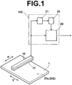
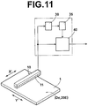
- Figure 1 is a schematic diagram that illustrates the configuration of an image processing apparatus 100 according to an embodiment of the present invention.
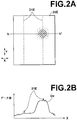
- Figure 2A illustrates an image represented by an image data set, which has been detected and obtained by line sensors.
- Figure 2B is a graph that illustrates the pixel values of the image data set, which has been detected and obtained by line sensors.
- the image processing apparatus 100 of the present embodiment illustrated in Figure 1 is that which executes image processes on an image data set that represents an original image 20E borne by an original 1, which is an image carrier, obtained by relatively moving the original 1 in a sub scanning direction (indicated by arrow Y' in Figure 1 ) with respect to a line sensor 10, which is a photoelectric conversion element array, that comprises a great number of photoreceptors arranged in a main scanning direction (indicated by arrow X' in Figure 1 ), which intersects with the sub scanning direction, while the line sensor 10 detects light emitted by the original 1 when illuminated.
- the image processing apparatus 100 comprises a line noise extracting means 30; a preprocessing means 31; and a subtracting means 40.
- the line noise extracting means 30 executes a filter process on the image data set that represents the original image 20E to extract image data that represent line noise components (hereinafter, referred to as "striped blur components 21E") that extend in the sub scanning direction (indicated by arrow Y in Figure 2 ) within the original image 20E.
- the preprocessing means 31 executes a preprocess that reduces drastic changes in pixel values of the image data set that represents the original image 20E, in a first direction (indicated by arrow X in Figure 2 ) perpendicular to the sub scanning direction, prior to the filter process executed by the line noise extracting means 30.
- the subtracting means 40 subtracts the image data that represent the striped blur components 21E from the image data set that represents the original image 20E.
- the sub scanning direction of the original image 20E corresponds to the sub scanning direction (indicated by arrow Y' in Figure 1 ), in which the original 1 is relatively moved with respect to the line sensor 10.
- the line noise extracting means 30 is also capable of executing a filter process on the image data set that represents the original image 20E to extract striped blur components that extend in the main scanning direction within the original image 20E.
- the preprocessing means 31 is also capable of executing a preprocess that reduces drastic changes in pixel values of the image data set that represents the original image 20E, in a second direction perpendicular to the main scanning direction, prior to the filter process executed by the line noise extracting means 30.
- the main scanning direction of the original image 20E corresponds to the main scanning direction (indicated by arrow X' in Figure 1 ), in which the great number of photoreceptors of the line sensor 10 are arranged.
- the striped blur components 21E are mainly generated due to differences in the properties of the individual photoreceptors that constitute the line sensor 10. In actuality, a great number of striped blurs of various sizes that extend in the sub scanning direction of the original image 20E may be generated. However, only two large striped blur components 21E of the original image 20E are illustrated in Figure 2A .
- the pixel values illustrated in the graph of Figure 2B represent pixel values of image data which are positioned on a line h-h', which extends in the first direction of the original image 20E.
- the image data set that represents the original image 20E also includes a region in which the pixel values change drastically in the first direction.
- the preprocessing means 31 obtains difference data that represents differences among pixel data De, which are adjacent in the first direction, of the image data set that represents the original image 20E. Next, the preprocessing means 31 executes a process to reduce the absolute values of the difference data that exceeds a predetermined threshold value, then cumulatively adds the processed difference data in the first direction. Alternatively, the preprocessing means 31 obtains difference data that represents differences among pixel data De, which are adjacent in the first direction, of the image data set that represents the original image 20E. Next, the preprocessing means 31 obtains running averages of the difference data in the first direction.
- the preprocessing means 31 executes a process to reduce the absolute values of the difference data that correspond to pixel data, the values of which the running average exceeds a predetermined threshold value, then cumulatively adds the processed difference data in the first direction.
- the preprocessing means 31 obtains difference data that represents differences among pixel data De, which are adjacent in the second direction, of the image data set that represents the original image 20E.
- the preprocessing means 31 executes a process to reduce the absolute values of the difference data that exceeds a predetermined threshold value, then cumulatively adds the processed difference data in the second direction.
- the preprocessing means 31 obtains difference data that represents differences among pixel data De, which are adjacent in the second direction, of the image data set that represents the original image 20E.
- the preprocessing means 31 obtains running averages of the difference data in the second direction. Thereafter, the preprocessing means 31 executes a process to reduce the absolute values of the difference data that correspond to pixel data, the values of which the running average exceeds a predetermined threshold value, then cumulatively adds the processed difference data in the second direction. These processes will be described in detail later.
- the difference data that correspond to pixel data, of which the running average exceeds a predetermined threshold value and the corresponding pixel data represent the same positions in the original image 20E.
- the obtainment of the running averages is an example of a filtering process.
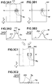
- Figures 3A1, 3A2, 3B1, 3B2, 3C1, and 3C2 illustrate the manner in which striped blur components are extracted without executing the preprocess.
- Figure 3A1 shows an original image 20E
- Figure 3A2 is a graph that illustrates the values of image data that represent the original image 20E.
- Figure 3B1 shows an image 20F represented by the image data that represents the original image 20E, to which a filter process has been executed
- Figure 3B2 is a graph that illustrates the values of image data that represent the image of Figure 3B1.
- Figure 3C1 shows the striped blur components, which have been extracted from the original image 20E
- Figure 3C2 is a graph that illustrates the values of image data that represent the striped blur components. Note that the above graphs that illustrate the values of image data illustrate the values of image data positioned along the line h-h', which extends in the first direction of each of the images.
- Image data Df that represents the image 20F is obtained by executing a low pass filter process in the first direction on the image data De that represents the original image 20E.
- the image data Df comprises low frequency components.
- the image 20F is a blurred and spread out image.
- a region Rf within the image 20F corresponds to a region Re within the image 20e, where pixel values of the image data De change drastically in the first direction. Pixel values of the image data Df in the vicinity of the region Rf change greatly from the pixel values of the image data De in the corresponding region (refer to Figures 3B1 and 3B2 ).
- Image data Dg comprising high frequency components, is obtained by subtracting the image data Df from the image data De, which represent the original image 20E.
- An image 20G represented by the image data Dg, includes rippled portions (ringing components) in the first direction in the vicinity of a region Rg, which corresponds to the region Re, in addition to striped blur components 21G (refer to Figures 3C1 and 3C2 ).
- the ringing components represent the difference in pixel values of the image data De and the image data Df in the vicinity of the region Rg.
- Image data that represent striped blur components can be extracted from the original image 20E without generating the ringing components, by the preprocessing means 31 executing the preprocess, prior to the administration of the filter process.
- Figures 4A, 4B, 4C, and 4D illustrate the manner in which the preprocess is executed.
- Figure 4A is a graph that illustrates the values of image data that represent the original image 20E.
- Figure 4B is a graph that illustrates the values of difference data of the image data.
- Figure 4C is a graph that illustrates the values of the running averages of the difference data.
- Figure 4D is a graph that illustrates the values of image data, in which the values of the difference data corresponding to running averages that exceed a predetermined threshold value are converted to zero.
- Figures 5A and 5B show image data, in which the zero value difference data is cumulatively added.
- Figure 5A shows an image represented by the cumulatively added image data
- Figure 5B is a graph that illustrates the values of the cumulatively added image data.
- the preprocess executed by the preprocessing means 31 comprises the following steps.
- the preprocessing means 31 obtains image data Se that represent the differences in pixel values among image data De, which are adjacent in the first direction of the original image 20E. Specifically, for example, consider a case of three pixel data values, De1, De2, and De3, which are adjacent in the first direction.
- a difference value U1 which is the value obtained when pixel data De1 is subtracted from pixel data De2, is obtained.
- the difference value U1 is designated as the value of pixel data Se1, which is positioned at a position corresponding to that represented by the pixel data De1 within the image 20E.
- a difference value U2 which is the value obtained when pixel data De2 is subtracted from pixel data De3, is obtained.
- the difference value U2 is designated as the value of pixel data Se2, which is positioned at a position corresponding to that represented by the pixel data De2 within the image 20E. In this manner, an image data set Se, which represents the entirety of the difference data, is obtained.
- the preprocessing means 31 obtains image data He, which represents running averages in the first direction, of the pixel values of the image data Se. Specifically, the values of three pixel data Se1, Se2, and Se3 are averaged, to obtain a value V2.
- the value V2 is designated as the value of pixel data He2, which is positioned at a position corresponding to that represented by the pixel data Se2 within the image 20E. In this manner, an image data set He, which represents the entirety of the running averages, is obtained.
- the preprocessing means 31 obtains image data Te.
- the image data Te is obtained by executing a process that reduces the absolute values of the image data He that exceed a threshold value ⁇ Kh. Specifically, for example, the values of pixel data He1, He2, and He3, which are positive values that exceed the threshold value +Kh, are converted to zero.
- the image data Te is obtained in this manner. That is, the image data Te is that in which values of pixel data corresponding to regions J1 and J2, where pixel values of the image data De change drastically in the first direction.
- the threshold value ⁇ Kh is determined to enable separation of image data that represent the regions J1 and J2, where pixel values change drastically and ringing components are conspicuously generated during extraction of the striped blur components, from image data that represent other regions.
- the determination of the threshold value also separates striped blur components from linear image information components.
- image data De' is obtained, by cumulatively adding the image data Te in the first direction.
- the value of pixel data De'1 is derived by sequentially adding (cumulatively adding) values of the image data Te from one end in the first direction (the side of h, on the line h-h') .
- the value of pixel data Te1 is added to the value of pixel data De' 1, to obtain the value of pixel data De'2, then the value of pixel data Te2 is added to the value of pixel data De'2 to obtain the value of pixel data De'3. Calculations are repeated in this manner to obtain an image data set De', that represents the entirety of the cumulatively added image data, is obtained.
- the image data set De' obtained in this manner corresponds to the image data De, with the drastic changes in pixel values in the first direction of the original image 20E being reduced.
- Figure 5A shows an image 20E', which is represented by the image data set De' .
- Regions J1 and J2 within the graph of Figure 5B are those in which the drastic changes in the pixel values of the image data De have been reduced.
- a threshold ⁇ Ks may be determined with respect to the image data Se that represent the difference among adjacent pixels of the image data De. Then, a process may be executed to reduce the absolute values of image data Se having values that exceed the threshold value ⁇ Ks. Finally, an image data set, in which drastic changes in pixel values in the first direction of the image are reduced, may be generated by cumulatively adding the processed image data Se in the same manner as above.
- the capabilities of separating the regions at which ringing components are conspicuously generated from other regions differ between the case in which a threshold value is determined for the image data Se and the case in which a threshold value is determined for the image data He.
- components represented by image data have more low frequency components than striped blur components (high frequency components).
- the running averaging process attenuates high frequency components, therefore the capability of separating the striped blur components from the image data is improved.
- a filter process (for example, a low pass filter process) is executed in the first direction on the image data set De', to extract striped blur components 21E'.
- Figures 6A1, 6A2, 6B1, 6B2, 6C1, and 6C2 illustrate the manner in which striped blur components are extracted by the filter process.
- Figure 6A1 shows an image represented by image data on which the preprocess has been executed
- Figure 6A2 is a graph that illustrates the values of image data that represent the preprocessed image
- Figure 6B1 shows the preprocessed image represented by image data on which a filter process has been executed
- Figure 6B2 is a graph that illustrates the values of image data that represent the image of Figure 6B1.
- Figure 6C1 shows the striped blur components, which have been extracted
- Figure 3C2 is a graph that illustrates the values of image data that represent the striped blur components. Note that the above graphs that illustrate the values of image data illustrate the values of image data positioned along the line h-h', which extends in the first direction of each of the images.
- the line noise extracting means 30 executes a low pass filter process in the first direction (indicated by arrow X in Figure 6A1 ) on the image data set De' to obtain an image data set Db that represents an image 20B comprising low frequency components. Then, the line noise extracting means 30 subtracts the image data set Db from the image data set De', to obtain an image data set Dc that represents an image 20C comprising high frequency components.
- the image 20C is an image that shows the striped blur components 21E'.
- the process to extract image data that represent the striped blur components may further comprise the step of executing a low pass filter process in the sub scanning direction following the low pass filter process in the first direction, to obtain an image data set Db' that represents an image 20B'.
- the image data that represent the striped blur components is extracted from the image data set De', in which drastic changes of pixel values in the first direction have been reduced by the pre process.
- the generation of ringing components is suppressed during extraction of the image data that represent the striped blur components, compared to the comparative example, in which the filter process is executed on the image data set De, which has not been preprocessed.
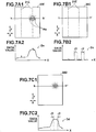
- Figures 7A1, 7A2, 7B1, 7B2, 7C1, and 7C2 illustrate the manner in which striped blur components are removed from an image.
- Figure 7A1 shows the original image
- Figure 7A2 is a graph that illustrates the values of image data that represent the original image.
- Figure 7B1 shows the extracted striped blur components
- Figure 7B2 is a graph that illustrates the values of image data that represent the striped blur components.
- Figure 7C1 show the original image, from which the striped blur components have been removed
- Figure 7C2 is a graph that illustrates the values of image data that represent the image of Figure 7C1 . Note that the above graphs that illustrate the values of image data illustrate the values of image data positioned along the line h-h', which extends in the first direction of each of the images.
- the subtracting means 40 subtracts the striped blur components 21E from the original image 20E. That is, the image data set Dc, which represents the image 20C comprising high frequency components, is subtracted from the image data set De, which represents the original image De. Thereby, an image data set Dd that represents an image 20D, which is the original image 20E having the striped blur components 21E removed therefrom, is obtained.
- loss of linear image information components associated with removal of striped blur components can be suppressed.
- Figures 8A and 8B show two dimensional spectra of images.
- Figure 8A shows a two dimensional spectrum of the original image
- Figure 8B shows a two dimensional spectrum of the image from which striped blur components have been removed.
- a two dimensional spectrum 25E of the original image 20E which includes the striped blur components 21E, is obtained by two dimensional Fourier transform.
- the striped blur components 21E appear in regions 26, which represent low frequency components in the sub scanning direction (indicated by arrow Y in Figure 8A ), and high frequency components in the first direction (indicated by arrow X in Figure 8A ) .
- the values of the pixels of the image data set Dc that represents the striped blur components 21E are subtracted from the image data set De as is.
- spectrum components that include the striped blur components are substantially removed from regions 26E' of a two dimensional spectrum 25E', which is obtained by Fourier transform of the image from which the striped blur components have been removed.
- the regions 26E' correspond to the regions 26E of the two dimensional spectrum 25E. That is, specific spectrum components corresponding to the regions 26E' are substantially absent in the image from which the striped blur components have been removed. Therefore, differences may be present in the quality of the image 20D and the original image 20E.
- a filter Fe is approximated by filters Fe1, Fe2, Fe3, Fe4, and Fe5, each having different ranges for running averages, as shown in Figure 9 .
- the image data sets are passed through the filters Fe1, Fe2, Fe3, Fe4, and Fe5 as individual processes during the filter process.
- a filter process equivalent to passing the image data set through the filter Fe can be realized with a smaller amount of calculation. That is, multiplication processes during passing of the image data set through the filter Fe are substituted by addition processes during passing of the image data set through the filters Fe1, Fe2, Fe3, Fe4, and Fe5, thereby reducing the total amount of calculation.
- the preprocess may be executed after the image data set that represents the original image is passed through a filter or the like, to reduce high or low frequency components in the sub scanning direction, in which the striped blur components extend.
- the process to extract the striped blur components may be that in which preprocessed image data that includes the striped blur components is passed through a high pass filter. That is, a filter may be employed that extracts high frequency components in the first direction.
- the changing of the magnitude of the values of each of the pixel data of the image data that represent the striped components during removal of the striped components from the original image by the subtracting means may be realized with conversion tables or conversion functions.
- the present invention is applicable to cases in which striped blur components extend in the main scanning direction of an image, or cases in which striped blur components extend in both the main and sub scanning directions of an image.
- the generation of ringing components is suppressed while extracting image data that represent the striped blur components in these cases as well, thereby suppressing the inclusion of ringing components in a processed image.
- the technique of extracting image data that represent striped blur components while suppressing the generation of the ringing components is applicable to striped blur components that extend in directions other than the main and sub directions as well.
- the image carrier (original) may be a radiation image conversion panel for recording radiation images, formed by layering a stimulable phosphor layer on a substrate (refer to Unexamined Japanese Patent Publication No. 2001-13599 , for example).
- image data that represent the radiation images are obtained by detecting stimulated phosphorescence with a line sensor.
- the stimulated phosphorescence is emitted from the radiation image conversion panel by being irradiated with excitation light.
- the line sensor may be provided in a staggered manner.
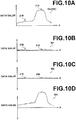
- the line noise extracting means 30 executes a filter process on an image data set De (refer to Figure 10A ) that represents the original image 20E, which includes the striped blur components 21E, to extract predetermined high frequency components therefrom. Thereby, image dataW1 (refer to Figure 10B ) that represent the striped blur components is extracted.
- a data converting means 35 obtains image data W2 (refer to Figure 10C ), in which the absolute values of each of the pixel data of the image data W1 are reduced by multiplying the values with a uniform coefficient, for example.
- the subtracting means 40 subtracts the image data W2, obtained in the manner described above, from the image data set De, to obtain image data W3 (refer to Figure 10D ), which represents the original image 20E having the striped blur components 21E removed therefrom.
- image data W3 (refer to Figure 10D )
- the oscillation width of the ringing components and the difference in quality between the images can be reduced.
- the loss of linear image information components, associated with the removal of striped blur components can also be reduced.
Applications Claiming Priority (2)
| Application Number | Priority Date | Filing Date | Title |
|---|---|---|---|
| JP2003315677 | 2003-09-08 | ||
| JP2003315677A JP4350468B2 (ja) | 2003-09-08 | 2003-09-08 | 画像処理方法および装置ならびにプログラム |
Publications (3)
| Publication Number | Publication Date |
|---|---|
| EP1513337A2 EP1513337A2 (en) | 2005-03-09 |
| EP1513337A3 EP1513337A3 (en) | 2007-07-25 |
| EP1513337B1 true EP1513337B1 (en) | 2019-05-01 |
Family
ID=34131938
Family Applications (1)
| Application Number | Title | Priority Date | Filing Date |
|---|---|---|---|
| EP04020659.1A Active EP1513337B1 (en) | 2003-09-08 | 2004-08-31 | Method, apparatus, and program for image processing |
Country Status (3)
| Country | Link |
|---|---|
| US (1) | US7657112B2 (ja) |
| EP (1) | EP1513337B1 (ja) |
| JP (1) | JP4350468B2 (ja) |
Families Citing this family (16)
| Publication number | Priority date | Publication date | Assignee | Title |
|---|---|---|---|---|
| JP5424580B2 (ja) * | 2008-05-30 | 2014-02-26 | 富士フイルム株式会社 | 画像処理装置および画像処理装置の作動方法ならびにプログラム |
| JP4879938B2 (ja) * | 2008-06-27 | 2012-02-22 | 富士フイルム株式会社 | 画像処理装置および方法ならびにプログラム |
| JP5288919B2 (ja) * | 2008-07-15 | 2013-09-11 | 富士フイルム株式会社 | 画像撮影装置 |
| JP5361267B2 (ja) * | 2008-07-18 | 2013-12-04 | 富士フイルム株式会社 | 信号ライン補正方法および装置 |
| US8265346B2 (en) | 2008-11-25 | 2012-09-11 | De La Rue North America Inc. | Determining document fitness using sequenced illumination |
| US8780206B2 (en) * | 2008-11-25 | 2014-07-15 | De La Rue North America Inc. | Sequenced illumination |
| JP5315157B2 (ja) * | 2009-07-27 | 2013-10-16 | キヤノン株式会社 | 情報処理装置、ライン状ノイズ低減処理方法、及びプログラム |
| US8749767B2 (en) * | 2009-09-02 | 2014-06-10 | De La Rue North America Inc. | Systems and methods for detecting tape on a document |
| JP5302838B2 (ja) * | 2009-09-30 | 2013-10-02 | 富士フイルム株式会社 | 画像処理装置、画像処理方法、画像処理プログラム、および、x線画像撮影装置 |
| JP5543194B2 (ja) * | 2009-12-24 | 2014-07-09 | キヤノン株式会社 | 情報処理装置、処理方法及びプログラム |
| US8433124B2 (en) * | 2010-01-07 | 2013-04-30 | De La Rue North America Inc. | Systems and methods for detecting an optically variable material |
| US8509492B2 (en) * | 2010-01-07 | 2013-08-13 | De La Rue North America Inc. | Detection of color shifting elements using sequenced illumination |
| US9053596B2 (en) | 2012-07-31 | 2015-06-09 | De La Rue North America Inc. | Systems and methods for spectral authentication of a feature of a document |
| US9245214B2 (en) | 2014-06-27 | 2016-01-26 | Ricoh Company Ltd. | Image processing compression with a defined pixel window in a linear array |
| US20170337669A1 (en) * | 2014-12-24 | 2017-11-23 | Sony Corporation | Image processing device, image processing method, and program |
| JP2016027932A (ja) * | 2015-11-26 | 2016-02-25 | キヤノン株式会社 | 画像処理装置、画像処理方法、プログラム、及び記憶媒体 |
Citations (3)
| Publication number | Priority date | Publication date | Assignee | Title |
|---|---|---|---|---|
| US5666434A (en) * | 1994-04-29 | 1997-09-09 | Arch Development Corporation | Computer-aided method for image feature analysis and diagnosis in mammography |
| US5903680A (en) * | 1996-02-05 | 1999-05-11 | U.S. Philips Corporation | Image data recursive noise filter with reduced temporal filtering of higher spatial frequencies |
| US20030091243A1 (en) * | 2001-11-14 | 2003-05-15 | Fuji Photo Film Co., Ltd. | Periodical pattern suppression processing method and apparatus |
Family Cites Families (6)
| Publication number | Priority date | Publication date | Assignee | Title |
|---|---|---|---|---|
| JPH0294962A (ja) * | 1988-09-30 | 1990-04-05 | Fuji Photo Film Co Ltd | 画像信号補正方法 |
| US5068909A (en) * | 1989-05-18 | 1991-11-26 | Applied Imaging Corporation | Method and apparatus for generating quantifiable video displays |
| JPH03270567A (ja) * | 1990-03-20 | 1991-12-02 | Fuji Photo Film Co Ltd | 画像信号補正方法 |
| JP3472596B2 (ja) * | 1993-06-11 | 2003-12-02 | 株式会社日立製作所 | ノイズ低減フィルター |
| JP2000036033A (ja) | 1998-07-21 | 2000-02-02 | Toshiba Eng Co Ltd | 明暗検査装置および明暗検査方法 |
| JP2002314999A (ja) * | 2001-04-12 | 2002-10-25 | Nikon Corp | 画像圧縮装置、画像圧縮プログラムおよび電子カメラ |
-
2003
- 2003-09-08 JP JP2003315677A patent/JP4350468B2/ja not_active Expired - Fee Related
-
2004
- 2004-08-31 EP EP04020659.1A patent/EP1513337B1/en active Active
- 2004-09-07 US US10/934,688 patent/US7657112B2/en active Active
Patent Citations (3)
| Publication number | Priority date | Publication date | Assignee | Title |
|---|---|---|---|---|
| US5666434A (en) * | 1994-04-29 | 1997-09-09 | Arch Development Corporation | Computer-aided method for image feature analysis and diagnosis in mammography |
| US5903680A (en) * | 1996-02-05 | 1999-05-11 | U.S. Philips Corporation | Image data recursive noise filter with reduced temporal filtering of higher spatial frequencies |
| US20030091243A1 (en) * | 2001-11-14 | 2003-05-15 | Fuji Photo Film Co., Ltd. | Periodical pattern suppression processing method and apparatus |
Also Published As
| Publication number | Publication date |
|---|---|
| US7657112B2 (en) | 2010-02-02 |
| EP1513337A2 (en) | 2005-03-09 |
| EP1513337A3 (en) | 2007-07-25 |
| JP4350468B2 (ja) | 2009-10-21 |
| JP2005084902A (ja) | 2005-03-31 |
| US20050053306A1 (en) | 2005-03-10 |
Similar Documents
| Publication | Publication Date | Title |
|---|---|---|
| EP1513337B1 (en) | Method, apparatus, and program for image processing | |
| US4074231A (en) | Pattern processing system | |
| US7529425B2 (en) | Denoising method, apparatus, and program | |
| US7043078B2 (en) | Method and apparatus for segmentation of compound documents having low resolution halftones | |
| EP1174824B1 (en) | Noise reduction method utilizing color information, apparatus, and program for digital image processing | |
| Russo | A method for estimation and filtering of Gaussian noise in images | |
| JPH09503329A (ja) | 文書中の前景情報を背景情報から分離する方法 | |
| WO2003079695A1 (en) | Method and apparatus for processing sensor images | |
| CN113155466B (zh) | 轴承故障视觉振动检测方法及系统 | |
| US4916722A (en) | X-ray image processing apparatus | |
| EP0946047B1 (en) | Method for low complexity, low memory inverse dithering | |
| KR100754969B1 (ko) | 화상 검사 장치, 화상 검사 방법 및 컴퓨터 판독가능한 기억 매체 | |
| US7359567B2 (en) | Signal processing apparatus for eliminating ringing signal and method thereof, record medium, and program | |
| KR100864337B1 (ko) | 화상 노이즈 저감 방법 및 장치 | |
| US7760963B2 (en) | Image processing method, image processing device and recording medium on which image processing program is recorded | |
| Kao | Modification of the LULU operators for preservation of critical image details | |
| JPH05346956A (ja) | 画像信号の処理装置 | |
| KR101418961B1 (ko) | 영상의 노이즈 세기를 추정하고 이를 이용하여 적응적으로영상을 처리하는 영상처리 시스템 및 방법 | |
| KR100213013B1 (ko) | 영상의 명암대비 개선회로 | |
| EP4181054B1 (en) | Data processing method for rapidly suppressing high-frequency background noise in a digitized image | |
| Prasad et al. | Multilevel Pipelined Processing for Aerial Image Restoration | |
| De Grandi et al. | Speckle filtering, segmentation and classification of polarimetric SAR data: A unified approach based on the wavelet transform | |
| Kira | Image Denoising Using First O | |
| CN101779221A (zh) | 改进色度锐度的方法和设备 | |
| KR940006838B1 (ko) | 평균값 및 분산값을 이용한 스페클 이미지 처리방법 |
Legal Events
| Date | Code | Title | Description |
|---|---|---|---|
| PUAI | Public reference made under article 153(3) epc to a published international application that has entered the european phase |
Free format text: ORIGINAL CODE: 0009012 |
|
| AK | Designated contracting states |
Kind code of ref document: A2 Designated state(s): AT BE BG CH CY CZ DE DK EE ES FI FR GB GR HU IE IT LI LU MC NL PL PT RO SE SI SK TR |
|
| AX | Request for extension of the european patent |
Extension state: AL HR LT LV MK |
|
| RAP1 | Party data changed (applicant data changed or rights of an application transferred) |
Owner name: FUJIFILM CORPORATION |
|
| PUAL | Search report despatched |
Free format text: ORIGINAL CODE: 0009013 |
|
| AK | Designated contracting states |
Kind code of ref document: A3 Designated state(s): AT BE BG CH CY CZ DE DK EE ES FI FR GB GR HU IE IT LI LU MC NL PL PT RO SE SI SK TR |
|
| AX | Request for extension of the european patent |
Extension state: AL HR LT LV MK |
|
| 17P | Request for examination filed |
Effective date: 20071127 |
|
| 17Q | First examination report despatched |
Effective date: 20080129 |
|
| AKX | Designation fees paid |
Designated state(s): DE FR NL |
|
| GRAP | Despatch of communication of intention to grant a patent |
Free format text: ORIGINAL CODE: EPIDOSNIGR1 |
|
| INTG | Intention to grant announced |
Effective date: 20181010 |
|
| GRAS | Grant fee paid |
Free format text: ORIGINAL CODE: EPIDOSNIGR3 |
|
| GRAJ | Information related to disapproval of communication of intention to grant by the applicant or resumption of examination proceedings by the epo deleted |
Free format text: ORIGINAL CODE: EPIDOSDIGR1 |
|
| GRAL | Information related to payment of fee for publishing/printing deleted |
Free format text: ORIGINAL CODE: EPIDOSDIGR3 |
|
| INTC | Intention to grant announced (deleted) | ||
| GRAR | Information related to intention to grant a patent recorded |
Free format text: ORIGINAL CODE: EPIDOSNIGR71 |
|
| GRAA | (expected) grant |
Free format text: ORIGINAL CODE: 0009210 |
|
| AK | Designated contracting states |
Kind code of ref document: B1 Designated state(s): DE FR NL |
|
| INTG | Intention to grant announced |
Effective date: 20190322 |
|
| REG | Reference to a national code |
Ref country code: DE Ref legal event code: R096 Ref document number: 602004053925 Country of ref document: DE |
|
| REG | Reference to a national code |
Ref country code: NL Ref legal event code: FP |
|
| PGFP | Annual fee paid to national office [announced via postgrant information from national office to epo] |
Ref country code: NL Payment date: 20190712 Year of fee payment: 16 |
|
| REG | Reference to a national code |
Ref country code: DE Ref legal event code: R097 Ref document number: 602004053925 Country of ref document: DE |
|
| PLBE | No opposition filed within time limit |
Free format text: ORIGINAL CODE: 0009261 |
|
| STAA | Information on the status of an ep patent application or granted ep patent |
Free format text: STATUS: NO OPPOSITION FILED WITHIN TIME LIMIT |
|
| 26N | No opposition filed |
Effective date: 20200204 |
|
| REG | Reference to a national code |
Ref country code: NL Ref legal event code: MM Effective date: 20200901 |
|
| PG25 | Lapsed in a contracting state [announced via postgrant information from national office to epo] |
Ref country code: NL Free format text: LAPSE BECAUSE OF NON-PAYMENT OF DUE FEES Effective date: 20200901 |
|
| P01 | Opt-out of the competence of the unified patent court (upc) registered |
Effective date: 20230515 |
|
| PGFP | Annual fee paid to national office [announced via postgrant information from national office to epo] |
Ref country code: FR Payment date: 20230703 Year of fee payment: 20 Ref country code: DE Payment date: 20230705 Year of fee payment: 20 |