EP1513237A1 - Elektrische Isolierungsvorrichtung eines Handhabungsgeräts - Google Patents
Elektrische Isolierungsvorrichtung eines Handhabungsgeräts Download PDFInfo
- Publication number
- EP1513237A1 EP1513237A1 EP04292049A EP04292049A EP1513237A1 EP 1513237 A1 EP1513237 A1 EP 1513237A1 EP 04292049 A EP04292049 A EP 04292049A EP 04292049 A EP04292049 A EP 04292049A EP 1513237 A1 EP1513237 A1 EP 1513237A1
- Authority
- EP
- European Patent Office
- Prior art keywords
- insert
- core
- arm
- cavity
- envelope
- Prior art date
- Legal status (The legal status is an assumption and is not a legal conclusion. Google has not performed a legal analysis and makes no representation as to the accuracy of the status listed.)
- Withdrawn
Links
- 238000002955 isolation Methods 0.000 title claims description 17
- 239000012777 electrically insulating material Substances 0.000 claims abstract description 4
- 239000007789 gas Substances 0.000 claims description 10
- IJGRMHOSHXDMSA-UHFFFAOYSA-N Atomic nitrogen Chemical compound N#N IJGRMHOSHXDMSA-UHFFFAOYSA-N 0.000 claims description 6
- 238000007791 dehumidification Methods 0.000 claims description 5
- 229920001296 polysiloxane Polymers 0.000 claims description 5
- 239000002274 desiccant Substances 0.000 claims description 4
- 239000002131 composite material Substances 0.000 claims description 3
- 239000011152 fibreglass Substances 0.000 claims description 3
- 239000011261 inert gas Substances 0.000 claims description 3
- 229910052757 nitrogen Inorganic materials 0.000 claims description 3
- 238000010292 electrical insulation Methods 0.000 abstract description 6
- XLYOFNOQVPJJNP-UHFFFAOYSA-N water Substances O XLYOFNOQVPJJNP-UHFFFAOYSA-N 0.000 description 6
- 230000007246 mechanism Effects 0.000 description 4
- 230000015572 biosynthetic process Effects 0.000 description 3
- 239000000428 dust Substances 0.000 description 3
- 230000002349 favourable effect Effects 0.000 description 3
- 238000012423 maintenance Methods 0.000 description 3
- 239000000463 material Substances 0.000 description 3
- 230000008439 repair process Effects 0.000 description 3
- 238000009825 accumulation Methods 0.000 description 2
- 230000008901 benefit Effects 0.000 description 2
- 230000005540 biological transmission Effects 0.000 description 2
- 239000004020 conductor Substances 0.000 description 2
- 229920001971 elastomer Polymers 0.000 description 2
- 239000000806 elastomer Substances 0.000 description 2
- 238000009413 insulation Methods 0.000 description 2
- 238000000034 method Methods 0.000 description 2
- 230000035939 shock Effects 0.000 description 2
- 229910000838 Al alloy Inorganic materials 0.000 description 1
- 229910000851 Alloy steel Inorganic materials 0.000 description 1
- VYPSYNLAJGMNEJ-UHFFFAOYSA-N Silicium dioxide Chemical compound O=[Si]=O VYPSYNLAJGMNEJ-UHFFFAOYSA-N 0.000 description 1
- PNEYBMLMFCGWSK-UHFFFAOYSA-N aluminium oxide Inorganic materials [O-2].[O-2].[O-2].[Al+3].[Al+3] PNEYBMLMFCGWSK-UHFFFAOYSA-N 0.000 description 1
- 238000005452 bending Methods 0.000 description 1
- 230000000295 complement effect Effects 0.000 description 1
- 230000007797 corrosion Effects 0.000 description 1
- 238000005260 corrosion Methods 0.000 description 1
- 239000006185 dispersion Substances 0.000 description 1
- 238000001035 drying Methods 0.000 description 1
- 238000005516 engineering process Methods 0.000 description 1
- 238000007765 extrusion coating Methods 0.000 description 1
- 230000002209 hydrophobic effect Effects 0.000 description 1
- 239000012212 insulator Substances 0.000 description 1
- 230000014759 maintenance of location Effects 0.000 description 1
- 230000004001 molecular interaction Effects 0.000 description 1
- 239000002808 molecular sieve Substances 0.000 description 1
- 230000003287 optical effect Effects 0.000 description 1
- 210000000056 organ Anatomy 0.000 description 1
- 230000035515 penetration Effects 0.000 description 1
- 230000009257 reactivity Effects 0.000 description 1
- 229920006395 saturated elastomer Polymers 0.000 description 1
- 239000000741 silica gel Substances 0.000 description 1
- 229910002027 silica gel Inorganic materials 0.000 description 1
- 229920006268 silicone film Polymers 0.000 description 1
- URGAHOPLAPQHLN-UHFFFAOYSA-N sodium aluminosilicate Chemical compound [Na+].[Al+3].[O-][Si]([O-])=O.[O-][Si]([O-])=O URGAHOPLAPQHLN-UHFFFAOYSA-N 0.000 description 1
- 239000010959 steel Substances 0.000 description 1
- 239000000126 substance Substances 0.000 description 1
- 239000002966 varnish Substances 0.000 description 1
- 238000009736 wetting Methods 0.000 description 1
Images

Classifications
-
- B—PERFORMING OPERATIONS; TRANSPORTING
- B66—HOISTING; LIFTING; HAULING
- B66F—HOISTING, LIFTING, HAULING OR PUSHING, NOT OTHERWISE PROVIDED FOR, e.g. DEVICES WHICH APPLY A LIFTING OR PUSHING FORCE DIRECTLY TO THE SURFACE OF A LOAD
- B66F11/00—Lifting devices specially adapted for particular uses not otherwise provided for
- B66F11/04—Lifting devices specially adapted for particular uses not otherwise provided for for movable platforms or cabins, e.g. on vehicles, permitting workmen to place themselves in any desired position for carrying out required operations
- B66F11/044—Working platforms suspended from booms
- B66F11/046—Working platforms suspended from booms of the telescoping type
-
- H—ELECTRICITY
- H01—ELECTRIC ELEMENTS
- H01B—CABLES; CONDUCTORS; INSULATORS; SELECTION OF MATERIALS FOR THEIR CONDUCTIVE, INSULATING OR DIELECTRIC PROPERTIES
- H01B17/00—Insulators or insulating bodies characterised by their form
- H01B17/32—Single insulators consisting of two or more dissimilar insulating bodies
- H01B17/325—Single insulators consisting of two or more dissimilar insulating bodies comprising a fibre-reinforced insulating core member
-
- H—ELECTRICITY
- H02—GENERATION; CONVERSION OR DISTRIBUTION OF ELECTRIC POWER
- H02G—INSTALLATION OF ELECTRIC CABLES OR LINES, OR OF COMBINED OPTICAL AND ELECTRIC CABLES OR LINES
- H02G1/00—Methods or apparatus specially adapted for installing, maintaining, repairing or dismantling electric cables or lines
- H02G1/02—Methods or apparatus specially adapted for installing, maintaining, repairing or dismantling electric cables or lines for overhead lines or cables
Definitions
- the invention relates to an isolation device for a handling device, as well as a lift truck equipped with such a device.
- the voltage requires intervention of an operator who, placed in the nacelle of a machine elevator, handle the cable concerned driver then same as this one is under tension.
- This manipulation can take place either at distance by means of an insulating pole when the nature intervention allows, either directly when the the nature of the intervention requires it, the operator with or without electrically insulating gloves.
- the lifting machines are usually equipped with a deployable lift mechanism with multiple moving arms, including kinematics can be of the compass type (the arms being pivoting), or telescopic (the arms being sliding).
- Document EP-0 940 366 is also known from lifting machine whose upper arm is provided with a disc radial, called umbrella, coated with a silicone varnish, and intended to increase the resistance to wetting of said arm to limit the propagation of leakage currents.
- This technology can give complete satisfaction when weather and terrain conditions are satisfactory.
- the invention aims in particular to remedy disadvantages mentioned above, by proposing a device electrical insulation which, while further limiting the propagation of leakage currents, even in case of bad weather, sufficiently robust for allow interventions in all conditions of ground.
- the invention proposes a device electrical insulation for a handling device equipped with an arm, this device comprising an insert electrically insulating material for forming a portion of said arm, this insert having a rigid tubular core which made of an electrically insulating material, is covered with a radially elastomeric casing ribbed over most of its length.
- the ribbed envelope ensures efficient drainage of the water, thus hindering the formation on the surface of the insert of a conductive aqueous film.
- the envelope being relatively resistant to shocks and friction against possible obstacles that might be in the vicinity of the zone of intervention, it gives the insert a increased resistance.
- the invention also relates to a lifting machine including such an isolation device.
- the envelope is for example ribbed such way that the ratio between the leakage line of the insert (i.e., the length of the insert measured along its outer surface) and its overall length is greater than or equal to 2.
- the envelope can in particular be ribbed such so that this ratio is between 2 and 3.
- the envelope has a continuous helical rib, which is example inclined relative to a plane perpendicular to the axis of the insert.
- the core of the insert is preferably made in a composite material, such as a fiberglass.
- the electrical isolation device comprises at least one attachment end rigidly attached to one end of the insert, and intended to be fixed on a portion adjacent tubular arm of the handling device.
- the device insulation has two rigidly attached to each end of the insert and intended for to be respectively fixed on each of said portions coaxial.
- the (or each) tip is attached to the end of the insert by hooping and bonding, this fastening being completed by screwing or a pinning.
- the electrical insulation device may include a dehumidification system of the sealed cavity delimited by the insert.
- This dehumidification system includes example a gas supply connected to the cavity, and arranged to maintain a gas pressure therein above atmospheric pressure.
- the gas employed is preferably an inert gas, for example nitrogen.
- a desiccant is preferably placed in the inner cavity.
- FIG. 1 a device of 1.
- This is a machine of lifting used for maintenance of power lines, in particular high voltage power lines.
- This machine compotes a motor vehicle 2 equipped with a telescopic lifting mechanism 3 comprising a plurality of sliding arms 4, 5, 6 interlocked with each other in others.
- the machine 1 also comprises, in accordance with the mode embodiment shown in FIG. 1, an upper arm 7 pivoting, which is connected at one of its ends said lower 8, the last 6 of the arms of the mechanism elevator 3 by a hinge 9 and which supports its opposite end, said upper 10, a nacelle 11 intended to accommodate an operator 12 in charge of a intervention on a power line 13.
- the nacelle 11 is equipped with a mast 14, allowing, in particular, nacelle 11 to take support on line 13 or keep it at a fixed distance from platform 11 to facilitate the operator's interventions on the line 13.
- the operator 12 - and thus the nacelle 11 - is at the same potential as the power line 13, while the vehicle 2 is at ground potential.
- the apparatus 1 is equipped with a device 15 designed to electrically isolate the nacelle 11 from the rest 1. As we shall see later, this device 15 is arranged to prevent the propagation of leakage currents from the power line 13, in particularly in wet weather.
- this electrical insulation device 15 has an insert electrically insulating 16 forming a portion of the arm 7.
- This insert 16 is inserted between two coaxial portions of the upper arm, namely a portion 17, situated on the side of the nacelle 11, and a lower portion 18 located on the side of the articulation 9.
- the insert 16 is generally cylindrical. It has a rigid tubular core 19 made of a material electrically insulating, covered with an envelope 20 elastomer, preferably silicone, which is radially grooved over most of its length.
- an envelope 20 elastomer preferably silicone
- the envelope presents for example a series of ribs spaced apart.
- the casing 20 has a helical groove 21 which extends over the entire length of the insert 16.
- the core 19 forms the body of the insert 16; he is designed to support the load including the nacelles 11 and the operators 12 there.
- the core 19 is, of preferably made of a composite material, such as a fiberglass, which gives the insert 16 excellent mechanical properties of resistance to bending and to torsion, as well as a high electrical resistivity.
- the envelope 20 it can be put on the core 19 by the technique usually used for the cable sheathing, namely the extrusion coating, However, this technique will be adapted for the training of the radial rib 21.
- the end of the extruder of a rotating disk provided with a notch and whose rotation is controlled according to the speed in advance of the elastomer in the tube of the extruder, and of the pitch chosen for the helical rib 21.
- the rib 21 presents in section a asymmetric profile: it is inclined with respect to a plane perpendicular to the axis A of the insert 16, since the upper portion 17 to the lower portion 18. results in better runoff of rainwater in case bad weather.
- l the overall length of the insert 16, i.e. the shortest distance measured parallel to the axis A of the insert, separating the ends 22, 23 thereof.
- L the creepage of the insert 16, that is to say the distance separating the ends 22, 23 of the insert 16, measured axially along the contour of the outer surface 24 of the envelope 20.
- the rib 21 so that the ratio R characteristic of the insert 16 is greater than or equal to 2, for example between 2 and 3.
- the insert 16 present, compared to a conventional tubular insert of same resistance to propagation of leakage currents, overall length three times less.
- an insert 16 of a length out all of it has the same resistance to propagation leakage currents that a classic tubular insert with an overall length of 3 m.
- silicone material hydrophobic for producing the envelope 20 promotes the dispersion of water into fine droplets, thus avoiding the formation of a conductive aqueous film.
- the rib 21 have a ridge device 26 ui promotes the drip of water and the drying of the surface 24 of the envelope 20. It avoids as well as is formed on the surface 24 of the envelope 20 a continuous film favorable to the propagation of currents of leak.
- the envelope 20 is not in the form of a simple film covering the core 19, but under the form of a thick layer (relative to the thickness radial core 19), resistant to shocks and friction against possible obstacles, such as branching in the vicinity of the area intervention.
- This resistance is also favored by flexibility and elasticity of the rib 21.
- the insert 16 is mounted so as to ensure not only the mechanical continuity of the arm top 7, but also the transmission of the order movements of the nacelle 11 and organs of which it is equipped.
- the isolation device 15 comprises two fasteners 27 attached to the ends 22, 23 of the insert 16.
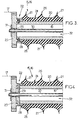
- Each end 27 comprises for example a disc circular 25 of which protrudes a tubular portion 28 centered on the axis A of the insert 16, and fretted (pressed by force) on the end of the core 19 while being glued to it.
- the tubular portion 28 is in additionally secured in a manner complementary to the core 19, by radial screwing ( Figure 3) or by means of one or more radial or diametral pins ( Figure 4).
- the end pieces 27 are made of a material Rigid enough to hold the interface between the end portions 17, 18 of the arm 7 and the insert 16. They are for example made steel or aluminum alloy.
- the ends 27 can be pierced with a hole 29 to allow the watertight passage of a cable of control 30, in particular hydraulic or optical.
- a cover 31 is fitted in the hole 29 for ensure the tight passage of the control cable 30 to through the mouthpiece 27.
- the electrical isolation device 15 is equipped with a dehumidification system 33 of the cavity 32.
- This system 33 comprises a gas supply 34 connected to the cavity 32 by means of a pipe 35 passing through one of the attachment ferrules 27.
- the power supply 34 is arranged to maintain the cavity 32 a gas pressure greater than the pressure atmospheric. It comprises for example a compressor or a pressure regulator connected to a gas tank (not shown)
- the overpressure prevailing in the cavity 32 makes it possible to limit the penetration into it of moisture and surrounding dust.
- a desiccant pad may further be placed in the cavity 32 to retain the steam of water by molecular interaction.
- the desiccant for example activated alumina, molecular sieve or silica gel
- the desiccant for example activated alumina, molecular sieve or silica gel
- the pulsed gas is preferably a inert gas (such as nitrogen) chosen for its absence chemical reactivity with the various components of the electrical isolation device 15, so in particular to avoid corrosion of fasteners 27.
- a inert gas such as nitrogen
Landscapes
- Engineering & Computer Science (AREA)
- Structural Engineering (AREA)
- Life Sciences & Earth Sciences (AREA)
- Geology (AREA)
- Mechanical Engineering (AREA)
- Insulators (AREA)
- Forklifts And Lifting Vehicles (AREA)
- Wind Motors (AREA)
Applications Claiming Priority (2)
| Application Number | Priority Date | Filing Date | Title |
|---|---|---|---|
| FR0310051A FR2859048B1 (fr) | 2003-08-20 | 2003-08-20 | Dispositif d'isolation electrique pour un engin de manutention |
| FR0310051 | 2003-08-20 |
Publications (1)
| Publication Number | Publication Date |
|---|---|
| EP1513237A1 true EP1513237A1 (de) | 2005-03-09 |
Family
ID=34112835
Family Applications (1)
| Application Number | Title | Priority Date | Filing Date |
|---|---|---|---|
| EP04292049A Withdrawn EP1513237A1 (de) | 2003-08-20 | 2004-08-13 | Elektrische Isolierungsvorrichtung eines Handhabungsgeräts |
Country Status (3)
| Country | Link |
|---|---|
| US (1) | US20050045355A1 (de) |
| EP (1) | EP1513237A1 (de) |
| FR (1) | FR2859048B1 (de) |
Cited By (3)
| Publication number | Priority date | Publication date | Assignee | Title |
|---|---|---|---|---|
| RU2399578C1 (ru) * | 2009-01-11 | 2010-09-20 | Открытое акционерное общество "Казанский электромеханический завод" | Подъемник автомобильный гидравлический |
| EP2554508A1 (de) * | 2011-08-04 | 2013-02-06 | Aldercote Ltd | Verbesserungen an oder im Zusammenhang mit einer Zugangsplattformvorrichtung |
| CN103956596A (zh) * | 2014-04-25 | 2014-07-30 | 国家电网公司 | 一种压接式跳线引流金具 |
Families Citing this family (6)
| Publication number | Priority date | Publication date | Assignee | Title |
|---|---|---|---|---|
| US20170099888A1 (en) * | 2015-10-12 | 2017-04-13 | Kevin James Flynn | Electrical safety device |
| CN106829754B (zh) * | 2017-03-24 | 2018-05-22 | 徐州海伦哲专用车辆股份有限公司 | 一种绝缘高空作业车及其绝缘工作平台自动限幅方法 |
| CA2986535A1 (en) * | 2017-10-18 | 2019-04-18 | Quanta Associates, L.P. | Systems and methods for drying and cleaning an aerial lift electrically insulated boom |
| CA3158861A1 (en) * | 2022-05-12 | 2023-11-12 | Quanta Associates, L.P. | Air gap boom cover system and method for drying an insulated boom section of an aerial lift device |
| CN115535864B (zh) * | 2022-09-30 | 2025-09-19 | 国网山东省电力公司滨州供电公司 | 一种变电站室内便携式挂线装置 |
| US12577092B2 (en) | 2022-10-04 | 2026-03-17 | Altec Industries, Inc. | Electrical insulation liner for aerial lift platform door |
Citations (4)
| Publication number | Priority date | Publication date | Assignee | Title |
|---|---|---|---|---|
| US3554319A (en) * | 1967-11-17 | 1971-01-12 | Simon Eng Dudley Ltd | Structures |
| JPS63174505A (ja) * | 1987-01-13 | 1988-07-19 | 住友電気工業株式会社 | 活線工事用ロボツト |
| JPH06287000A (ja) * | 1993-04-01 | 1994-10-11 | Sumitomo Electric Ind Ltd | 配電作業用ロボットシステム |
| JPH077822A (ja) * | 1992-06-26 | 1995-01-10 | Chubu Electric Power Co Inc | 配電線作業用マニピュレータの絶縁アーム |
Family Cites Families (7)
| Publication number | Priority date | Publication date | Assignee | Title |
|---|---|---|---|---|
| US4243118A (en) * | 1979-03-05 | 1981-01-06 | Landry Milton E | Non-conductive safety line and method |
| GB8312892D0 (en) * | 1983-05-11 | 1983-06-15 | Raychem Ltd | Electrical insulator |
| US4877422A (en) * | 1988-11-01 | 1989-10-31 | Gk Technologies, Inc. | Mobile aerial lift with boom structure having insulated boom section containing a clean, moisture free environment and method |
| CH685078A5 (de) * | 1992-06-15 | 1995-03-15 | Hubbell Inc | Isolator mit innerer Durchführung. |
| FR2727561B1 (fr) * | 1994-11-30 | 1996-12-20 | Sediver | Isolateur electrique, procede de fabrication d'un tel isolateur et dispositif pour la mise en oeuvre du procede |
| DE19629796C5 (de) * | 1996-07-24 | 2004-12-16 | Lapp Insulator Gmbh & Co. Kg | Kunststoffverbundisolator mit spiralförmigem Schirm und Verfahren zu seiner Herstellung |
| US6138470A (en) * | 1997-12-04 | 2000-10-31 | Fedders Corporation | Portable liquid desiccant dehumidifier |
-
2003
- 2003-08-20 FR FR0310051A patent/FR2859048B1/fr not_active Expired - Lifetime
-
2004
- 2004-08-13 EP EP04292049A patent/EP1513237A1/de not_active Withdrawn
- 2004-08-18 US US10/922,490 patent/US20050045355A1/en not_active Abandoned
Patent Citations (4)
| Publication number | Priority date | Publication date | Assignee | Title |
|---|---|---|---|---|
| US3554319A (en) * | 1967-11-17 | 1971-01-12 | Simon Eng Dudley Ltd | Structures |
| JPS63174505A (ja) * | 1987-01-13 | 1988-07-19 | 住友電気工業株式会社 | 活線工事用ロボツト |
| JPH077822A (ja) * | 1992-06-26 | 1995-01-10 | Chubu Electric Power Co Inc | 配電線作業用マニピュレータの絶縁アーム |
| JPH06287000A (ja) * | 1993-04-01 | 1994-10-11 | Sumitomo Electric Ind Ltd | 配電作業用ロボットシステム |
Non-Patent Citations (2)
| Title |
|---|
| PATENT ABSTRACTS OF JAPAN vol. 1995, no. 01 28 February 1995 (1995-02-28) * |
| PATENT ABSTRACTS OF JAPAN vol. 1995, no. 04 31 May 1995 (1995-05-31) * |
Cited By (3)
| Publication number | Priority date | Publication date | Assignee | Title |
|---|---|---|---|---|
| RU2399578C1 (ru) * | 2009-01-11 | 2010-09-20 | Открытое акционерное общество "Казанский электромеханический завод" | Подъемник автомобильный гидравлический |
| EP2554508A1 (de) * | 2011-08-04 | 2013-02-06 | Aldercote Ltd | Verbesserungen an oder im Zusammenhang mit einer Zugangsplattformvorrichtung |
| CN103956596A (zh) * | 2014-04-25 | 2014-07-30 | 国家电网公司 | 一种压接式跳线引流金具 |
Also Published As
| Publication number | Publication date |
|---|---|
| FR2859048A1 (fr) | 2005-02-25 |
| FR2859048B1 (fr) | 2005-12-23 |
| US20050045355A1 (en) | 2005-03-03 |
Similar Documents
| Publication | Publication Date | Title |
|---|---|---|
| EP1513237A1 (de) | Elektrische Isolierungsvorrichtung eines Handhabungsgeräts | |
| FR2500638A1 (fr) | Cable a fibres optiques | |
| CA2164069C (fr) | Isolateur electrique, procede de fabrication d'un tel isolateur et dispositif pour la mise en oeuvre du procede | |
| FR2491685A1 (fr) | Installation d'antenne actionnee par un moteur | |
| EP0754623B1 (de) | Anschlussvorrichtung für einen Enteiser eines Hubschrauberrotors | |
| FR2464696A1 (fr) | Attache cranienne d'extension | |
| FR2503476A1 (fr) | Procede de depose d'une gaine protectrice sur l'extremite d'un cable electrique et dispositif pour la mise en oeuvre de celui-ci | |
| FR2781198A1 (fr) | Perfectionnements aux installations de connexion de degivrage pour rotor de giravion | |
| WO2014102508A2 (fr) | Detection d'avarie d'une bande de captage | |
| EP0200244B1 (de) | Kupplungsvorrichtung für eine Umhüllung und einen Bestandteil ausserhalb dieser Umhüllung | |
| CA1245420A (fr) | Dispositif pour la realisation de galeries dans les cloisons composites | |
| FR2722238A1 (fr) | Ensemble de mesure comportant des moyens d'orientation d'une partie des elements de mesure | |
| EP3380728A1 (de) | Windturbinenschaufel mit einer plattierschicht mit optimiertem flächengewicht | |
| FR2706724A1 (fr) | Liaison électrique d'un vitrage. | |
| WO2005054874A1 (fr) | Joint tournant pour sonde de pression multifonction, a palette mobile | |
| EP0794347A1 (de) | Schutzfaltenbalg für einen Antrieb | |
| FR2892382A1 (fr) | Pale de giravion munie d'un volet orientable a l'aide d'au moins une rotule principale dont le premier arbre est solidaire de ladite pale. | |
| EP2957938B1 (de) | Längskabel und verlegeverfahren eines solchen kabels | |
| EP0797281B1 (de) | Verfahren und Vorrichtung zum Aufbringen einer elastischen rohrförmigen Umhüllung unter Klemmwirkung auf ein Element | |
| CA1282129C (fr) | Jonction souple pour cable sous-marin au papier impregne | |
| EP0071894B1 (de) | Vorrichtung zum Vermeiden einer Beschädigung eines Unterwasserverbindungskabels bei einem Gehäuseausgang während des Durchgangs auf einer Trommel und einer Rolle | |
| EP0043762B1 (de) | Aufblasbare Struktur mit Öffnung | |
| CA1317021C (fr) | Dispositif pour capter des ondes acoustiques se propageant dans l'eau | |
| FR2495551A2 (fr) | Ensemble de prise de courant a deperchage et reperchage automatiques pour vehicules a traction electrique, notamment les trolleybus | |
| FR2818238A1 (fr) | Perfectionnements aux rotors de giravion a pales a repliage automatique et installation de connexion electrique des pales |
Legal Events
| Date | Code | Title | Description |
|---|---|---|---|
| PUAI | Public reference made under article 153(3) epc to a published international application that has entered the european phase |
Free format text: ORIGINAL CODE: 0009012 |
|
| AK | Designated contracting states |
Kind code of ref document: A1 Designated state(s): AT BE BG CH CY CZ DE DK EE ES FI FR GB GR HU IE IT LI LU MC NL PL PT RO SE SI SK TR |
|
| AX | Request for extension of the european patent |
Extension state: AL HR LT LV MK |
|
| RAP1 | Party data changed (applicant data changed or rights of an application transferred) |
Owner name: ELECTRICITE DE FRANCE |
|
| AKX | Designation fees paid | ||
| REG | Reference to a national code |
Ref country code: DE Ref legal event code: 8566 |
|
| STAA | Information on the status of an ep patent application or granted ep patent |
Free format text: STATUS: THE APPLICATION IS DEEMED TO BE WITHDRAWN |
|
| 18D | Application deemed to be withdrawn |
Effective date: 20050910 |