EP1512879A1 - Fixed type constant velocity universal joint - Google Patents
Fixed type constant velocity universal joint Download PDFInfo
- Publication number
- EP1512879A1 EP1512879A1 EP04255244A EP04255244A EP1512879A1 EP 1512879 A1 EP1512879 A1 EP 1512879A1 EP 04255244 A EP04255244 A EP 04255244A EP 04255244 A EP04255244 A EP 04255244A EP 1512879 A1 EP1512879 A1 EP 1512879A1
- Authority
- EP
- European Patent Office
- Prior art keywords
- guide grooves
- center
- balls
- joint member
- spherical surface
- Prior art date
- Legal status (The legal status is an assumption and is not a legal conclusion. Google has not performed a legal analysis and makes no representation as to the accuracy of the status listed.)
- Granted
Links
Images


Classifications
-
- F—MECHANICAL ENGINEERING; LIGHTING; HEATING; WEAPONS; BLASTING
- F16—ENGINEERING ELEMENTS AND UNITS; GENERAL MEASURES FOR PRODUCING AND MAINTAINING EFFECTIVE FUNCTIONING OF MACHINES OR INSTALLATIONS; THERMAL INSULATION IN GENERAL
- F16D—COUPLINGS FOR TRANSMITTING ROTATION; CLUTCHES; BRAKES
- F16D3/00—Yielding couplings, i.e. with means permitting movement between the connected parts during the drive
- F16D3/16—Universal joints in which flexibility is produced by means of pivots or sliding or rolling connecting parts
- F16D3/20—Universal joints in which flexibility is produced by means of pivots or sliding or rolling connecting parts one coupling part entering a sleeve of the other coupling part and connected thereto by sliding or rolling members
- F16D3/22—Universal joints in which flexibility is produced by means of pivots or sliding or rolling connecting parts one coupling part entering a sleeve of the other coupling part and connected thereto by sliding or rolling members the rolling members being balls, rollers, or the like, guided in grooves or sockets in both coupling parts
- F16D3/223—Universal joints in which flexibility is produced by means of pivots or sliding or rolling connecting parts one coupling part entering a sleeve of the other coupling part and connected thereto by sliding or rolling members the rolling members being balls, rollers, or the like, guided in grooves or sockets in both coupling parts the rolling members being guided in grooves in both coupling parts
- F16D3/2237—Universal joints in which flexibility is produced by means of pivots or sliding or rolling connecting parts one coupling part entering a sleeve of the other coupling part and connected thereto by sliding or rolling members the rolling members being balls, rollers, or the like, guided in grooves or sockets in both coupling parts the rolling members being guided in grooves in both coupling parts where the grooves are composed of radii and adjoining straight lines, i.e. undercut free [UF] type joints
-
- F—MECHANICAL ENGINEERING; LIGHTING; HEATING; WEAPONS; BLASTING
- F16—ENGINEERING ELEMENTS AND UNITS; GENERAL MEASURES FOR PRODUCING AND MAINTAINING EFFECTIVE FUNCTIONING OF MACHINES OR INSTALLATIONS; THERMAL INSULATION IN GENERAL
- F16D—COUPLINGS FOR TRANSMITTING ROTATION; CLUTCHES; BRAKES
- F16D3/00—Yielding couplings, i.e. with means permitting movement between the connected parts during the drive
- F16D3/16—Universal joints in which flexibility is produced by means of pivots or sliding or rolling connecting parts
- F16D3/20—Universal joints in which flexibility is produced by means of pivots or sliding or rolling connecting parts one coupling part entering a sleeve of the other coupling part and connected thereto by sliding or rolling members
- F16D3/22—Universal joints in which flexibility is produced by means of pivots or sliding or rolling connecting parts one coupling part entering a sleeve of the other coupling part and connected thereto by sliding or rolling members the rolling members being balls, rollers, or the like, guided in grooves or sockets in both coupling parts
- F16D3/223—Universal joints in which flexibility is produced by means of pivots or sliding or rolling connecting parts one coupling part entering a sleeve of the other coupling part and connected thereto by sliding or rolling members the rolling members being balls, rollers, or the like, guided in grooves or sockets in both coupling parts the rolling members being guided in grooves in both coupling parts
- F16D3/224—Universal joints in which flexibility is produced by means of pivots or sliding or rolling connecting parts one coupling part entering a sleeve of the other coupling part and connected thereto by sliding or rolling members the rolling members being balls, rollers, or the like, guided in grooves or sockets in both coupling parts the rolling members being guided in grooves in both coupling parts the groove centre-lines in each coupling part lying on a sphere
- F16D3/2245—Universal joints in which flexibility is produced by means of pivots or sliding or rolling connecting parts one coupling part entering a sleeve of the other coupling part and connected thereto by sliding or rolling members the rolling members being balls, rollers, or the like, guided in grooves or sockets in both coupling parts the rolling members being guided in grooves in both coupling parts the groove centre-lines in each coupling part lying on a sphere where the groove centres are offset from the joint centre
-
- F—MECHANICAL ENGINEERING; LIGHTING; HEATING; WEAPONS; BLASTING
- F16—ENGINEERING ELEMENTS AND UNITS; GENERAL MEASURES FOR PRODUCING AND MAINTAINING EFFECTIVE FUNCTIONING OF MACHINES OR INSTALLATIONS; THERMAL INSULATION IN GENERAL
- F16D—COUPLINGS FOR TRANSMITTING ROTATION; CLUTCHES; BRAKES
- F16D3/00—Yielding couplings, i.e. with means permitting movement between the connected parts during the drive
- F16D3/16—Universal joints in which flexibility is produced by means of pivots or sliding or rolling connecting parts
- F16D3/20—Universal joints in which flexibility is produced by means of pivots or sliding or rolling connecting parts one coupling part entering a sleeve of the other coupling part and connected thereto by sliding or rolling members
- F16D3/22—Universal joints in which flexibility is produced by means of pivots or sliding or rolling connecting parts one coupling part entering a sleeve of the other coupling part and connected thereto by sliding or rolling members the rolling members being balls, rollers, or the like, guided in grooves or sockets in both coupling parts
- F16D3/223—Universal joints in which flexibility is produced by means of pivots or sliding or rolling connecting parts one coupling part entering a sleeve of the other coupling part and connected thereto by sliding or rolling members the rolling members being balls, rollers, or the like, guided in grooves or sockets in both coupling parts the rolling members being guided in grooves in both coupling parts
- F16D2003/22303—Details of ball cages
-
- F—MECHANICAL ENGINEERING; LIGHTING; HEATING; WEAPONS; BLASTING
- F16—ENGINEERING ELEMENTS AND UNITS; GENERAL MEASURES FOR PRODUCING AND MAINTAINING EFFECTIVE FUNCTIONING OF MACHINES OR INSTALLATIONS; THERMAL INSULATION IN GENERAL
- F16D—COUPLINGS FOR TRANSMITTING ROTATION; CLUTCHES; BRAKES
- F16D3/00—Yielding couplings, i.e. with means permitting movement between the connected parts during the drive
- F16D3/16—Universal joints in which flexibility is produced by means of pivots or sliding or rolling connecting parts
- F16D3/20—Universal joints in which flexibility is produced by means of pivots or sliding or rolling connecting parts one coupling part entering a sleeve of the other coupling part and connected thereto by sliding or rolling members
- F16D3/22—Universal joints in which flexibility is produced by means of pivots or sliding or rolling connecting parts one coupling part entering a sleeve of the other coupling part and connected thereto by sliding or rolling members the rolling members being balls, rollers, or the like, guided in grooves or sockets in both coupling parts
- F16D3/223—Universal joints in which flexibility is produced by means of pivots or sliding or rolling connecting parts one coupling part entering a sleeve of the other coupling part and connected thereto by sliding or rolling members the rolling members being balls, rollers, or the like, guided in grooves or sockets in both coupling parts the rolling members being guided in grooves in both coupling parts
- F16D2003/22309—Details of grooves
-
- Y—GENERAL TAGGING OF NEW TECHNOLOGICAL DEVELOPMENTS; GENERAL TAGGING OF CROSS-SECTIONAL TECHNOLOGIES SPANNING OVER SEVERAL SECTIONS OF THE IPC; TECHNICAL SUBJECTS COVERED BY FORMER USPC CROSS-REFERENCE ART COLLECTIONS [XRACs] AND DIGESTS
- Y10—TECHNICAL SUBJECTS COVERED BY FORMER USPC
- Y10S—TECHNICAL SUBJECTS COVERED BY FORMER USPC CROSS-REFERENCE ART COLLECTIONS [XRACs] AND DIGESTS
- Y10S464/00—Rotary shafts, gudgeons, housings, and flexible couplings for rotary shafts
- Y10S464/904—Homokinetic coupling
- Y10S464/906—Torque transmitted via radially spaced balls
Definitions
- the present invention relates to a constant velocity universal joint used in power transmission in automobiles and various industrial machines, and more particularly to a fixed type constant velocity universal joint having eight balls.
- Constant velocity universal joints are classified into a fixed type not sliding in the axial direction, and a slidable type.
- Figs. 8a and 8b show a Rzeppa type constant velocity universal joint (hereinafter called BJ type) as a representative example of fixed type constant velocity universal joint.
- This constant velocity universal joint comprises an outer ring 11 as an outer joint member having six arcuate guide grooves 11b extending in the axial direction in an inner spherical surface 11a, an inner ring 12 as an inner joint member having six arcuate guide grooves 12b extending in the axial direction in an outer spherical surface 12a, six balls 13 disposed between the guide grooves 11b of the outer ring 11 and guide grooves 12b of the inner ring 12, and a cage 14 for retaining the balls 13.
- the inner ring 12 has a tooth profile, i.e. serration or spline, 12c to be coupled with the shaft part 15.
- the outer ring 11 and inner ring 12 form a certain angle, and the balls 13 guided in the cage 14 are maintained within a plane perpendicular to a bisector of angle ⁇ formed by the outer and inner ring 11 and 12, so that the constant velocity of the joint is assured.
- a constant velocity universal joint applicable to high angle (maximum joint angle 50°) was an undercut-free joint (called UJ type) comprising six balls 13, but by increasing the number of balls and reducing the ball diameter, a more compact UJ type having eight balls with same strength and durability has been developed (for example, see Japanese Patent Application laid-open under No. H9-317784).
- a fixed type constant velocity universal joint when torque is transmitted in a state of forming a working angle, in the cage pockets, the balls move in the circumferential direction, and also move in the radial direction at the same time (see Fig. 1).
- the wall thickness of the cage has been determined to set the minimum limit to satisfy the displacement of balls in the radial direction at the maximum joint angle, in other words, so that the ball contact point may settle within the cage pocket. This is because increase of wall thickness of the cage causes the depth of guide grooves in the outer and inner rings to be reduced, thereby lowering the durability life of the joint at high angle and high load.
- It is one aspect of the invention to present a fixed type constant velocity universal joint comprising an outer joint member having eight arcuate guide grooves extending in the axial direction in an inner spherical surface, an inner joint member having eight arcuate guide grooves extending in the axial direction in an outer spherical surface, eight balls disposed between the guide grooves of the outer joint member and guide grooves of the inner joint member, and a cage interposed between the outer joint member and inner joint member for retaining the balls, in which center of guide grooves of the outer joint member is offset from center of inner spherical surface, and center of guide grooves of the inner joint member is offset from center of outer spherical surface by equal distance to opposite sides in the axial direction, and the relation of 0.45 ⁇ B/A ⁇ 0.65 is established, where A stands for the wall thickness of the cage, and B the radial displacement of balls at maximum joint angle.
- a fixed type constant velocity universal joint comprising an outer joint member having eight arcuate guide grooves extending in the axial direction in an inner spherical surface, an inner joint member having eight arcuate guide grooves extending in the axial direction in an outer spherical surface, eight balls disposed between the guide grooves of the outer joint member and guide grooves of the inner joint member, and a cage interposed between the outer joint member and inner joint member for retaining the balls, in which center of guide grooves of the outer joint member is offset from center of inner spherical surface, and center of guide grooves of the inner joint member from center of outer spherical surface, by equal distance to opposite sides in the axial direction, and inner spherical surface of the cage is offset from outer spherical surface thereof to the opposite side by equal distance in the axial direction, and further straight portions having straight groove bottoms are provided in guide grooves of the outer joint member and inner joint member, and the relation of 0.65 ⁇ B/A ⁇ 0.
- Value R1 of ratio (F/PCR) of offset amount F to length PCR of line segment linking center of guide grooves of the outer joint member or center of guide grooves of the inner joint member and center of balls may be specified in a range of 0.069 ⁇ R1 ⁇ 0.121.
- Contact angle ⁇ of guide grooves and balls may preferably be in a range of 29° to 40°.
- the inversion start angle of wedge angle between guide grooves of the outer joint member and inner joint member becomes smaller, and when the wedge angle is inverted, the play of the balls in the guide grooves is increased, and hammering sound can be generated.
- the contact angle ⁇ of guide grooves and balls is set in a range 29° to 40°.
- the wedge angle refers to the angle formed by a common normal of load side contact point of balls and guide grooves of outer joint member, and a common normal of load side contact point of balls and guide grooves of inner joint member.
- the ordinary angle of vehicle is generally 9° or less. As the joint angle increases, the wedge angle comes to the minus side going down below zero. This change of sign of wedge angle below zero is called inversion of wedge angle.
- the following table shows the relation of the value R1 of ratio (F/PCR) of offset amount F to length PCR of line segment linking center of guide grooves of the outer joint member or center of guide grooves of the inner joint member and center of balls, contact angle ⁇ , and wedge angle inversion start angle.
- the fixed type constant velocity universal joint of the invention assures the specified thickness of the cage, and realizes a more lightweight and compact structure while having the durability life and high angle strength equivalent to that of the conventional fixed type constant velocity universal joint of six balls.
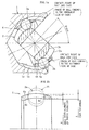
- Fig. 2a is a longitudinal sectional view of a joint
- Fig. 2b is a cross-sectional view of the joint
- Fig. 3 is a partial, magnified view of Fig. 2a.
- the fixed type constant velocity universal joint is mainly composed of an outer ring 1, an inner ring 2, balls 3, and a cage 4.
- the outer ring 1 as outer joint member is formed like a cup, and a shaft part for connecting with one of two shafts to be coupled is formed at the closed end side thereof.
- the outer ring 1 has a spherical inner circumference, that is, an inner spherical surface 1a, and eight arcuate guide grooves 1b extending in the axial direction are formed in the inner spherical surface 1a.
- the inner ring 2 as inner joint member has a tooth profile, i.e.
- the inner ring 2 has a spherical outer circumference, that is, an outer spherical surface 2a, and eight arcuate guide grooves 2b extending in the axial direction are formed in the outer spherical surface 2a.
- the guide grooves 1b of the outer ring 1 and guide grooves 2b of the inner ring 2 form pairs, and one ball is disposed in a ball track formed by each pair of guide grooves 1b and 2b.
- a total of eight balls 3 are retained at equal intervals in the circumferential direction by the cage 4.
- the cage 4 has concentric outer and inner spherical surfaces 4a and 4b, and the outer spherical surface 4a spherically contacts the inner spherical surface 1a of the outer ring 1, and the inner spherical surface 4b spherically contacts the outer spherical surface 2a of the inner ring 2.
- the center of the inner spherical surface 4b of the cage 4, and the center of the outer spherical surface 2a of the inner ring 1 as the guide surface of the inner spherical surface 4b of the cage 4 both coincide with the joint center O.
- Length PO 3 of line segment linking center P of guide grooves 1b of outer ring 1 and center O 3 of ball 3, and length QO 3 of line segment linking center Q of guide groove 2b of inner ring 2 and center O 3 of balls 3 are equal to each other, as indicated by PCR in Fig. 2a. Further, as shown in Fig.
- an angle formed between the line segment linking center P of guide grooves 1b of outer ring 1 and center O 3 of ball 3, and the line segment linking joint center O and center O 3 of balls 3 is called outer ring track offset angle ⁇ o
- an angle formed between the line segment linking center Q of guide grooves 2b of inner ring 2 and center O 3 of ball 3, and the line segment linking joint center O and center O 3 of balls 3 is called inner ring track offset angle ⁇ i
- the outer ring track offset angle ⁇ o and inner ring track ⁇ 1 are equal to each other.
- R1 0.104
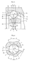
- FIG. 4 is a partial, magnified view of Fig. 2b, showing a mutual relation of outer ring 1, inner ring 2, and balls 3.
- Guide grooves 1b formed in the inner spherical surface 1a of the outer ring 1 have a Gothic arch cross section
- guide grooves 2b formed in the outer spherical surface 2a of the inner ring 2 have also a Gothic arch cross section. Therefore, the balls 3 contact the guide grooves 1b of the outer ring 1 at two points C 11 and C 12 , and contact guide grooves 2b of the inner ring 2 at two points C 21 and C 22 .
- Angle ⁇ formed by center O 3 of balls 3 corresponding to line segment passing the center O 3 of balls 3 and joint center O and contact points C 11 , C 12 , C 21 , C 22 with guide grooves 1b and 2b is the contact angle.
- Contact angles ⁇ of contact points C 11 , C 12 , C 21 , C 22 are all equal to each other, and set in a range of 29° to 40°.
- the contact angle ⁇ of 29° to 49° is smaller as compared with 37° to 45° in the conventional undercut-free joint of six balls, fixed type joint of six balls or fixed joint of eight balls.
- Fig. 5 is a magnified view in part of Fig. 3 for explaining the inversion start angle of wedge angle.
- the angle formed by common normal H 1 of contact point C 1 of balls 3 and guide grooves 1b of outer ring 1, and a common normal H 2 of contact point C 2 of balls 3 and guide grooves 2b of inner ring 2 is called the wedge angle 2 ⁇ .
- the common normal H 1 is a three-dimensional straight line linking the contact point of outer ring 1 and balls 3 and ball center O 3 .
- the common normal H 2 is a three-dimens ional straight line linking the contact point of inner ring 2 and balls 3 and ball center O 3 .
- Fig. 5 is a magnified view in part of Fig. 3 for explaining the inversion start angle of wedge angle.
- contact point C 1 of guide grooves 1b of outer ring 1 and balls 3 is inclined to the joint center surface passing through center O 3 of balls 3 by angle ⁇ owing to the arcuate guide grooves 1b.
- contact point C 2 of guide grooves 2b of inner ring 2 and balls 3 is inclined to the joint center plane passing through center O 3 of balls 3 by angle ⁇ owing to the arcuate guide grooves 2b.
- the wedge angle is equal to the sum 2 ⁇ of these wedge angles ⁇ .
- the wedge angle 2 ⁇ decreases in a certain phase along with increase of joint angle, and is then inverted.
- the joint angle upon start of inversion of wedge angle 2 ⁇ is set at 9° or higher.
- Fig. 6 shows an embodiment of UJ type. This embodiment is same as the embodiment in Fig. 1 except that a straight portion 1c is provided in the guide grooves 1b of the outer ring 1c, that a straight portion 1c is provided in the guide grooves 2b of the inner ring 2, and that the spherical centers p and q of the outer spherical surface 4a and inner spherical surface 4b of the cage 4 are offset in the opposite directions by equal distance f in the axial direction.
- Fig. 1a the joint in Fig. 2a has the maximum joint angle ⁇ max.
- the ball appearing at the upside in the drawing is indicated by reference numeral 3a, and the phase of this ball 3a is the phase of the ball coming to the innermost side of the cage.
- the ball appearing at the downside in the drawing is indicated by reference numeral 3b, and the phase of this ball 3b is the phase of the ball coming to the outermost side of the cage.
- FIG. 1b shows the balls 3a and 3b by double dot chain line in the longitudinal sectional view of the cage 4, in which the distance between centers of ball 3a and ball 3b indicated by character B is the radial displacement of the ball in the pocket 4c of the cage 4.
- the wall thickness of the cage 4 is the radial dimension of the peripheral wall of the pocket 4c, and it is indicated by character A in Fig. 1b.
- the wall thickness A of the cage 4 is defined to satisfy the range of 0.45 ⁇ B/A ⁇ 0.65 in the BJ type, and satisfy the range of 0.65 ⁇ B/A ⁇ 0.85 in the UJ type.
- the optimum value range of wall thickness of cage differs between the BJ type and UJ type because, as already explained in relation to Fig. 6, the UJ type has straight portions 1c and 2c in the guide grooves 1b and 2b of the outer and inner rings, and the guide grooves are shallower at the joint inner side as compared with the BJ type.
- T100 torque is a basic torque used in life calculation of constant velocity universal joint, and is the torque value determined from the contact stress (Hertz stress) of the guide grooves and balls of the outer ring and inner ring, and it means the torque capable of obtaining a life of 1500 hours at 100 rpm. As shown in Fig.
- an optimum wall thickness setting of the cage is required, and the range is as specified above (0.45 ⁇ B/A ⁇ 0.65 in the BJ type, and 0.65 ⁇ B/A ⁇ 0.85 in the UJ type).
Landscapes
- Engineering & Computer Science (AREA)
- General Engineering & Computer Science (AREA)
- Mechanical Engineering (AREA)
- Rolling Contact Bearings (AREA)
Abstract
Description
- The present invention relates to a constant velocity universal joint used in power transmission in automobiles and various industrial machines, and more particularly to a fixed type constant velocity universal joint having eight balls.
- Constant velocity universal joints are classified into a fixed type not sliding in the axial direction, and a slidable type. Figs. 8a and 8b show a Rzeppa type constant velocity universal joint (hereinafter called BJ type) as a representative example of fixed type constant velocity universal joint. This constant velocity universal joint comprises an
outer ring 11 as an outer joint member having sixarcuate guide grooves 11b extending in the axial direction in an inner spherical surface 11a, aninner ring 12 as an inner joint member having sixarcuate guide grooves 12b extending in the axial direction in an outerspherical surface 12a, sixballs 13 disposed between theguide grooves 11b of theouter ring 11 and guidegrooves 12b of theinner ring 12, and acage 14 for retaining theballs 13. - Centers P and Q of the
guide grooves guide groove 11b of theouter ring 11 is offset from center O of the inner spherical surface 11a to the opening side of theouter ring 11 by distance PO. The center Q ofguide groove 12b of theinner ring 12 is offset from center O of the outerspherical surface 12a to the inner side of theouter ring 11 by distance QO. The centers of inner spherical surface 11a of theouter ring 11 and outerspherical surface 12a of theinner ring 12 coincide with the joint center O. - One (not shown) of two shafts to be coupled is connected to the
outer ring 11, and other (shaft part 15) is connected to theinner ring 12. Accordingly, theinner ring 12 has a tooth profile, i.e. serration or spline, 12c to be coupled with theshaft part 15. Theouter ring 11 andinner ring 12 form a certain angle, and theballs 13 guided in thecage 14 are maintained within a plane perpendicular to a bisector of angle formed by the outer andinner ring - In a fixed type constant velocity universal joint, hitherto, a constant velocity universal joint applicable to high angle (maximum joint angle 50°) was an undercut-free joint (called UJ type) comprising six
balls 13, but by increasing the number of balls and reducing the ball diameter, a more compact UJ type having eight balls with same strength and durability has been developed (for example, see Japanese Patent Application laid-open under No. H9-317784). - In a fixed type constant velocity universal joint, when torque is transmitted in a state of forming a working angle, in the cage pockets, the balls move in the circumferential direction, and also move in the radial direction at the same time (see Fig. 1). In the conventional fixed type constant velocity universal joint of six balls, the wall thickness of the cage has been determined to set the minimum limit to satisfy the displacement of balls in the radial direction at the maximum joint angle, in other words, so that the ball contact point may settle within the cage pocket. This is because increase of wall thickness of the cage causes the depth of guide grooves in the outer and inner rings to be reduced, thereby lowering the durability life of the joint at high angle and high load.
- In the fixed type constant velocity universal joint of eight torque transmission balls realizing a more compact design and lighter weight, it is important that the strength at high joint angle should be kept same as that of the conventional constant velocity universal joint of six balls. To increase the strength of the cage, it is easy to increasing the wall thickness of the cage, but by increasing the thickness of the cage, the depth of the guide grooves of the outer and inner rings becomes shallower. As the guide grooves of the outer and inner rings become shallow, contact ellipses of balls can ride over the guide grooves at high angle and high torque load, and the durability life is lowered.
- It is hence an object of the invention to present a fixed type constant velocity universal joint of eight balls capable of satisfying two important functions, that is, assurance of cage strength at high angle and assurance of durability life at high angle and high torque load.
- It is other object of the invention to present a fixed type constant velocity universal joint of eight balls seeking the optimum thickness of cage in order to have the cage strength at high angle and durability life at high angle and high load equivalent to that of the conventional fixed type constant velocity universal joint of six balls.
- It is one aspect of the invention to present a fixed type constant velocity universal joint comprising an outer joint member having eight arcuate guide grooves extending in the axial direction in an inner spherical surface, an inner joint member having eight arcuate guide grooves extending in the axial direction in an outer spherical surface, eight balls disposed between the guide grooves of the outer joint member and guide grooves of the inner joint member, and a cage interposed between the outer joint member and inner joint member for retaining the balls, in which center of guide grooves of the outer joint member is offset from center of inner spherical surface, and center of guide grooves of the inner joint member is offset from center of outer spherical surface by equal distance to opposite sides in the axial direction, and the relation of 0.45 ≤ B/A ≤ 0.65 is established, where A stands for the wall thickness of the cage, and B the radial displacement of balls at maximum joint angle.
- It is other aspect of the invention to present a fixed type constant velocity universal joint comprising an outer joint member having eight arcuate guide grooves extending in the axial direction in an inner spherical surface, an inner joint member having eight arcuate guide grooves extending in the axial direction in an outer spherical surface, eight balls disposed between the guide grooves of the outer joint member and guide grooves of the inner joint member, and a cage interposed between the outer joint member and inner joint member for retaining the balls, in which center of guide grooves of the outer joint member is offset from center of inner spherical surface, and center of guide grooves of the inner joint member from center of outer spherical surface, by equal distance to opposite sides in the axial direction, and inner spherical surface of the cage is offset from outer spherical surface thereof to the opposite side by equal distance in the axial direction, and further straight portions having straight groove bottoms are provided in guide grooves of the outer joint member and inner joint member, and the relation of 0.65 ≤ B/A ≤ 0.85 is established, where A stans for the wall thickness of the cage, and B the radial displacement of balls at maximum joint angle.
- Value R1 of ratio (F/PCR) of offset amount F to length PCR of line segment linking center of guide grooves of the outer joint member or center of guide grooves of the inner joint member and center of balls may be specified in a range of 0.069 ≤ R1 ≤ 0.121.
- Contact angle α of guide grooves and balls may preferably be in a range of 29° to 40°. When the offset amount F is decreased, the inversion start angle of wedge angle between guide grooves of the outer joint member and inner joint member becomes smaller, and when the wedge angle is inverted, the play of the balls in the guide grooves is increased, and hammering sound can be generated. Accordingly, to set the wedge angle inversion start angle at least more than the ordinary angle of vehicle or the like, the contact angle α of guide grooves and balls is set in a range 29° to 40°. Herein, the wedge angle refers to the angle formed by a common normal of load side contact point of balls and guide grooves of outer joint member, and a common normal of load side contact point of balls and guide grooves of inner joint member. The ordinary angle of vehicle is generally 9° or less. As the joint angle increases, the wedge angle comes to the minus side going down below zero. This change of sign of wedge angle below zero is called inversion of wedge angle.
- The following table shows the relation of the value R1 of ratio (F/PCR) of offset amount F to length PCR of line segment linking center of guide grooves of the outer joint member or center of guide grooves of the inner joint member and center of balls, contact angle α, and wedge angle inversion start angle.
Value of ratio F/PCR Contact angle α (°) Inversion start angle of wedge angle (°) 0.069 45 8 40 9 29 14 0.121 45 14 40 16 29 25 - As known from Table 1, the smaller the contact angle α, the larger becomes the wedge angle inversion start angle. Also, the larger the offset amount F, the larger becomes the wedge angle inversion start angle. Therefore, as in the configuration described above, by setting the value R1 of ratio (F/PCR) of offset amount F to length PCR of line segment linking center of guide grooves of the outer joint member or center of guide grooves of the inner joint member and center of balls in a range of 0.069 ≤ R1 ≤ 0.121, and specifying the contact angle α of guide grooves and balls in a range of 29 degrees to 40 degrees, the contact ellipse of balls will not be dislocated from the guide grooves to ride over the spherical surface, and at least at the joint angle smaller than the ordinary joint angle of vehicle, play of balls in the guide grooves is eliminated, generation of hammering sound is prevented.
- The fixed type constant velocity universal joint of the invention assures the specified thickness of the cage, and realizes a more lightweight and compact structure while having the durability life and high angle strength equivalent to that of the conventional fixed type constant velocity universal joint of six balls.
- Referring now to the drawings, preferred embodiments of the invention will be described.
-
- Fig. 1a is a longitudinal sectional view of a joint for explaining the structure of the invention;
- Fig. 1b is a sectional view of a cage;
- Fig. 2a is a longitudinal sectional viewof joint according to an embodiment of the invention;
- Fig. 2b is a cross-sectional view of the joint shown in Fig.2a;
- Fig. 3 is a partial, magnified view of Fig. 2a;
- Fig. 4 is a partial, magnified view of Fig. 2b;
- Fig. 5 is a partial, magnified view of Fig. 3;
- Fig. 6 is a longitudinal sectional view of a joint according to other embodiment;
- Fig. 7 is a diagram showing the relation of cage strength and allowable load torque in terms of wall thickness of cage;
- Fig. 8a is a longitudinal sectional view of a conventional fixed type constant velocity universal joint; and
- Fig. 8b is a cross-sectional view of the joint shown in Fig. 8a.
-
- First, an embodiment of BJ type shown in Figs. 2a, 2b and Fig. 3 is explained. Fig. 2a is a longitudinal sectional view of a joint, and Fig. 2b is a cross-sectional view of the joint. Fig. 3 is a partial, magnified view of Fig. 2a.
- As shown in Figs. 2a, 2b and 3, the fixed type constant velocity universal joint is mainly composed of an
outer ring 1, aninner ring 2,balls 3, and acage 4. Theouter ring 1 as outer joint member is formed like a cup, and a shaft part for connecting with one of two shafts to be coupled is formed at the closed end side thereof. Theouter ring 1 has a spherical inner circumference, that is, an inner spherical surface 1a, and eightarcuate guide grooves 1b extending in the axial direction are formed in the inner spherical surface 1a. Theinner ring 2 as inner joint member has a tooth profile, i.e. serration or spline, 2d to be connected with other one (shaft part 5) of two shafts to be coupled. Theinner ring 2 has a spherical outer circumference, that is, an outerspherical surface 2a, and eightarcuate guide grooves 2b extending in the axial direction are formed in the outerspherical surface 2a. Theguide grooves 1b of theouter ring 1 and guidegrooves 2b of theinner ring 2 form pairs, and one ball is disposed in a ball track formed by each pair ofguide grooves balls 3 are retained at equal intervals in the circumferential direction by thecage 4. Thecage 4 has concentric outer and innerspherical surfaces spherical surface 4a spherically contacts the inner spherical surface 1a of theouter ring 1, and the innerspherical surface 4b spherically contacts the outerspherical surface 2a of theinner ring 2. - In this embodiment, centers P and Q of the
guide grooves outer ring 1 is offset from the center O of the inner spherical surface 1a to the opening side of theouter ring 1 by distance PO. The center ( inner ring track center) Q ofguide grooves 2b of theinner ring 2 is offset from the center O of the outerspherical surface 2a to the inner side of theouter ring 1 by distance QO. The center of the outerspherical surface 4a of thecage 4, and the center of the inner spherical surface 1a of theouter ring 1 as the guide surface of the outerspherical surface 4a of thecage 4 both coincide with the joint center O. Similarly, the center of the innerspherical surface 4b of thecage 4, and the center of the outerspherical surface 2a of theinner ring 1 as the guide surface of the innerspherical surface 4b of thecage 4 both coincide with the joint center O. Therefore, the offset amount (PO = F) of theouter ring 1 is the axial distance between the center P of theguide grooves 1b and the joint center O, and the offset amount (QO = F) of theinner ring 2 is the axial distance between the center Q of theguide grooves 2b and the joint center O, and the both are equal to each other. - Length PO3 of line segment linking center P of
guide grooves 1b ofouter ring 1 and center O3 ofball 3, and length QO3 of line segment linking center Q ofguide groove 2b ofinner ring 2 and center O3 ofballs 3 are equal to each other, as indicated by PCR in Fig. 2a. Further, as shown in Fig. 3, an angle formed between the line segment linking center P ofguide grooves 1b ofouter ring 1 and center O3 ofball 3, and the line segment linking joint center O and center O3 ofballs 3 is called outer ring track offset angle βo, and an angle formed between the line segment linking center Q ofguide grooves 2b ofinner ring 2 and center O3 ofball 3, and the line segment linking joint center O and center O3 ofballs 3 is called inner ring track offset angle βi, and the outer ring track offset angle βo and inner ring track β1 are equal to each other. - In this configuration, one (not shown) of two shafts to be coupled and
outer ring 1 are connected, and other (shaft part 5) andinner ring 2 are connected. When theouter ring 1 andinner ring 2 form a certain angle, theballs 3 guided in thecage 4 are maintained within a plane perpendicular to a bisector of angle formed by the outer andinner rings - As described above, the offset amount (F = PO = QO) of the
guide grooves - FIG. 4 is a partial, magnified view of Fig. 2b, showing a mutual relation of
outer ring 1,inner ring 2, andballs 3.Guide grooves 1b formed in the inner spherical surface 1a of theouter ring 1 have a Gothic arch cross section, and guidegrooves 2b formed in the outerspherical surface 2a of theinner ring 2 have also a Gothic arch cross section. Therefore, theballs 3 contact theguide grooves 1b of theouter ring 1 at two points C11 and C12, andcontact guide grooves 2b of theinner ring 2 at two points C21 and C22. Angle α formed by center O3 ofballs 3 corresponding to line segment passing the center O3 ofballs 3 and joint center O and contact points C11, C12, C21, C22 withguide grooves - Fig. 5 is a magnified view in part of Fig. 3 for explaining the inversion start angle of wedge angle. As mentioned above, the angle formed by common normal H1 of contact point C1 of
balls 3 and guidegrooves 1b ofouter ring 1, and a common normal H2 of contact point C2 ofballs 3 and guidegrooves 2b ofinner ring 2 is called the wedge angle 2τ. The common normal H1 is a three-dimensional straight line linking the contact point ofouter ring 1 andballs 3 and ball center O3. Similarly the common normal H2 is a three-dimens ional straight line linking the contact point ofinner ring 2 andballs 3 and ball center O3. As shown in Fig. 5, contact point C1 ofguide grooves 1b ofouter ring 1 andballs 3 is inclined to the joint center surface passing through center O3 ofballs 3 by angle τ owing to thearcuate guide grooves 1b. Similarly, contact point C2 ofguide grooves 2b ofinner ring 2 andballs 3 is inclined to the joint center plane passing through center O3 ofballs 3 by angle τ owing to thearcuate guide grooves 2b. The wedge angle is equal to the sum 2τ of these wedge angles τ. The wedge angle 2τ decreases in a certain phase along with increase of joint angle, and is then inverted. The joint angle upon start of inversion of wedge angle 2τ is set at 9° or higher. - Fig. 6 shows an embodiment of UJ type. This embodiment is same as the embodiment in Fig. 1 except that a
straight portion 1c is provided in theguide grooves 1b of theouter ring 1c, that astraight portion 1c is provided in theguide grooves 2b of theinner ring 2, and that the spherical centers p and q of the outerspherical surface 4a and innerspherical surface 4b of thecage 4 are offset in the opposite directions by equal distance f in the axial direction. - Referring back to Figs. 1a and 1b, in the fixed type constant velocity universal joint of eight balls, the cage strength at high angle and durability life at high angle and high load are compared with the conventional fixed type constant velocity universal joint of six balls, and the optimum value of the cage wall thickness for achieving the equivalent performance is explained. In Fig. 1a, the joint in Fig. 2a has the maximum joint angle max. The ball appearing at the upside in the drawing is indicated by
reference numeral 3a, and the phase of thisball 3a is the phase of the ball coming to the innermost side of the cage. The ball appearing at the downside in the drawing is indicated byreference numeral 3b, and the phase of thisball 3b is the phase of the ball coming to the outermost side of the cage. Fig. 1b shows theballs cage 4, in which the distance between centers ofball 3a andball 3b indicated by character B is the radial displacement of the ball in thepocket 4c of thecage 4. The wall thickness of thecage 4 is the radial dimension of the peripheral wall of thepocket 4c, and it is indicated by character A in Fig. 1b. - Supposing the wall thickness of the
cage 4 to be A and the radial displacement of theball 3 in one revolution of the joint to be B, the wall thickness A of thecage 4 is defined to satisfy the range of 0.45 ≤ B/A ≤ 0.65 in the BJ type, and satisfy the range of 0.65 ≤ B/A ≤ 0.85 in the UJ type. The optimum value range of wall thickness of cage differs between the BJ type and UJ type because, as already explained in relation to Fig. 6, the UJ type hasstraight portions guide grooves - The meaning of this numerical value range is illustrated in Fig. 7. In Fig. 7, the numerical values refer to the BJ type, but a similar tendency is noted in the UJ type, too. In the diagram, T100 torque is a basic torque used in life calculation of constant velocity universal joint, and is the torque value determined from the contact stress (Hertz stress) of the guide grooves and balls of the outer ring and inner ring, and it means the torque capable of obtaining a life of 1500 hours at 100 rpm. As shown in Fig. 7, at B/A < 0.45, in other words, when the cage wall thickness A is larger more than necessary than the radial displacement B of the
balls 3 in thepocket 4c of thecage 4, a sufficient strength of thecage 4 is assured, but the guide groove depth (inner side) of the inner and outer rings is too shallow, and the contact ellipse of theballs 3 can go out of the guide grooves at maximum joint angle, and the load torque is lowered extremely, and the joint function can be lost. On the other hand, at B/A > 0.65, in other words, when the cage wall thickness A is not sufficient as compared with the radial displacement B of theballs 3 in thepocket 4c of thecage 4, the guide groove depth (inner side) of the inner and outer rings is sufficient, and the contact ellipse of theballs 3 will not go out of the guide grooves. To the contrary, the wall thickness A of thecage 4 is not enough, and the cage strength at high angle cannot be assured. In the UJ type having eight balls, a similar tendency as in the BJ type is noted. Since the structure is thus different, the numerical value range is also different. - Thus, in order to satisfy the both important properties of cage strength at high angle and joint durability at high angle, an optimum wall thickness setting of the cage is required, and the range is as specified above (0.45 ≤ B/A ≤ 0.65 in the BJ type, and 0.65 ≤ B/A ≤ 0.85 in the UJ type).
Claims (4)
- A fixed type constant velocity universal joint comprising:wherein center of guide grooves of the outer joint member is offset from center of inner spherical surface, and center of guide grooves of the inner joint member is offset from center of outer spherical surface by equal distance (F) to opposite sides in the axial direction,an outer joint member having eight arcuate guide grooves extending in the axial direction in an inner spherical surface thereof,an inner joint member having eight arcuate guide grooves extending in the axial direction in an outer spherical surface thereof,eight balls disposed between the guide grooves of the outer joint member and guide grooves of the inner joint member, anda cage interposed between the outer joint member and inner joint member for retaining the balls,
characterized in that the relation of 0.45 ≤ B/A ≤ 0.65 is established, where A stands for the wall thickness of the cage, and B the radial displacement of balls at maximum joint angle. - The fixed type constant velocity universal joint of claim 1, characterized in that inner spherical surface of the cage is offset from outer spherical surface thereof to the opposite side by equal distance (f) in the axial direction, and that straight portions having straight groove bottoms are provided in guide grooves of the outer joint member and inner joint member.
- The fixed type constant velocity universal joint of claim 1 or 2, characterized in that value R1 of ratio (F/PCR) of offset amount (F) to length (PCR) of line segment linking center of guide grooves of the outer joint member or center of guide grooves of the inner joint member and center of balls is specified in a range of 0.069 ≤ R1 ≤ 0.121.
- The fixed type constant velocity universal joint of claim 1 or 2, characterized in that contact angle of guide grooves and balls is in a range of 29° to 40°.
Priority Applications (1)
| Application Number | Priority Date | Filing Date | Title |
|---|---|---|---|
| EP07001115.0A EP1770298B1 (en) | 2003-09-04 | 2004-08-31 | Fixed type constant velocity universal joint |
Applications Claiming Priority (2)
| Application Number | Priority Date | Filing Date | Title |
|---|---|---|---|
| JP2003313061A JP4223358B2 (en) | 2003-09-04 | 2003-09-04 | Fixed constant velocity universal joint |
| JP2003313061 | 2003-09-04 |
Related Child Applications (1)
| Application Number | Title | Priority Date | Filing Date |
|---|---|---|---|
| EP07001115.0A Division EP1770298B1 (en) | 2003-09-04 | 2004-08-31 | Fixed type constant velocity universal joint |
Publications (2)
| Publication Number | Publication Date |
|---|---|
| EP1512879A1 true EP1512879A1 (en) | 2005-03-09 |
| EP1512879B1 EP1512879B1 (en) | 2009-06-03 |
Family
ID=34131876
Family Applications (2)
| Application Number | Title | Priority Date | Filing Date |
|---|---|---|---|
| EP07001115.0A Expired - Lifetime EP1770298B1 (en) | 2003-09-04 | 2004-08-31 | Fixed type constant velocity universal joint |
| EP04255244A Expired - Lifetime EP1512879B1 (en) | 2003-09-04 | 2004-08-31 | Fixed type constant velocity universal joint |
Family Applications Before (1)
| Application Number | Title | Priority Date | Filing Date |
|---|---|---|---|
| EP07001115.0A Expired - Lifetime EP1770298B1 (en) | 2003-09-04 | 2004-08-31 | Fixed type constant velocity universal joint |
Country Status (5)
| Country | Link |
|---|---|
| US (1) | US7258616B2 (en) |
| EP (2) | EP1770298B1 (en) |
| JP (1) | JP4223358B2 (en) |
| CN (1) | CN100529450C (en) |
| DE (1) | DE602004021323D1 (en) |
Cited By (7)
| Publication number | Priority date | Publication date | Assignee | Title |
|---|---|---|---|---|
| EP1703158A1 (en) * | 2005-03-16 | 2006-09-20 | Ntn Corporation | Fixed constant velocity universal joint |
| WO2010099867A3 (en) * | 2009-03-02 | 2010-11-04 | Volkswagen Aktiengesellschaft | Constant velocity fixed joint |
| EP2299136A4 (en) * | 2008-06-13 | 2012-04-25 | Ntn Toyo Bearing Co Ltd | Fixed uniform-motion universal joint |
| EP2284411A4 (en) * | 2008-05-30 | 2012-05-09 | Ntn Toyo Bearing Co Ltd | Fixed type, constant velocity universal joint |
| CN103216540A (en) * | 2013-04-01 | 2013-07-24 | 浙江欧迪恩传动科技股份有限公司 | Rzeppa universal joint with double pressure angles |
| EP2594820A4 (en) * | 2010-07-15 | 2014-06-18 | Jtekt Corp | Constant-velocity ball joint |
| KR101467913B1 (en) * | 2013-09-11 | 2014-12-02 | 한국델파이주식회사 | Constant velocity universal joint |
Families Citing this family (11)
| Publication number | Priority date | Publication date | Assignee | Title |
|---|---|---|---|---|
| US8162764B2 (en) | 2004-02-13 | 2012-04-24 | Ntn Corporation | Constant velocity universal joint |
| JP4879501B2 (en) * | 2005-03-25 | 2012-02-22 | Ntn株式会社 | High angle fixed type constant velocity universal joint |
| US8147342B2 (en) | 2005-03-22 | 2012-04-03 | Ntn Corporation | Fixed-type constant-velocity universal joint |
| DE102005029042A1 (en) * | 2005-06-21 | 2007-01-11 | Volkswagen Ag | Fixed constant velocity joint |
| JP5073190B2 (en) * | 2005-09-22 | 2012-11-14 | Ntn株式会社 | Sliding constant velocity universal joint |
| JP4994689B2 (en) * | 2006-03-27 | 2012-08-08 | Ntn株式会社 | Fixed constant velocity universal joint |
| JP5241078B2 (en) * | 2006-03-31 | 2013-07-17 | Ntn株式会社 | Fixed constant velocity universal joint |
| JP2008025641A (en) * | 2006-07-19 | 2008-02-07 | Ntn Corp | Constant velocity universal joint |
| CN104806650B (en) * | 2014-03-18 | 2017-11-21 | 万向钱潮股份有限公司 | A kind of fixing end constant velocity cardan joint |
| JP6658319B2 (en) * | 2016-06-08 | 2020-03-04 | トヨタ自動車株式会社 | Fixed constant velocity joint |
| CN112020613B (en) * | 2018-04-24 | 2023-11-14 | Ntn株式会社 | Sliding constant velocity universal coupling for transmission shaft |
Citations (1)
| Publication number | Priority date | Publication date | Assignee | Title |
|---|---|---|---|---|
| US20020032064A1 (en) * | 1995-12-26 | 2002-03-14 | Keisuke Sone | Constant velocity joint having eight torque transmitting balls |
Family Cites Families (3)
| Publication number | Priority date | Publication date | Assignee | Title |
|---|---|---|---|---|
| JP3859267B2 (en) * | 1996-05-28 | 2006-12-20 | Ntn株式会社 | Fixed type constant velocity universal joint |
| US20030017877A1 (en) * | 2001-04-24 | 2003-01-23 | Masazumi Kobayashi | Constant velocity universal joint |
| US20030054893A1 (en) * | 2001-09-20 | 2003-03-20 | Delphi Technologies Inc. | Constant velocity joint |
-
2003
- 2003-09-04 JP JP2003313061A patent/JP4223358B2/en not_active Expired - Lifetime
-
2004
- 2004-08-31 DE DE602004021323T patent/DE602004021323D1/en not_active Expired - Lifetime
- 2004-08-31 EP EP07001115.0A patent/EP1770298B1/en not_active Expired - Lifetime
- 2004-08-31 EP EP04255244A patent/EP1512879B1/en not_active Expired - Lifetime
- 2004-09-01 US US10/931,207 patent/US7258616B2/en not_active Expired - Lifetime
- 2004-09-02 CN CN200410073705.2A patent/CN100529450C/en not_active Expired - Lifetime
Patent Citations (1)
| Publication number | Priority date | Publication date | Assignee | Title |
|---|---|---|---|---|
| US20020032064A1 (en) * | 1995-12-26 | 2002-03-14 | Keisuke Sone | Constant velocity joint having eight torque transmitting balls |
Non-Patent Citations (1)
| Title |
|---|
| PATENT ABSTRACTS OF JAPAN vol. 1998, no. 04 31 March 1998 (1998-03-31) * |
Cited By (16)
| Publication number | Priority date | Publication date | Assignee | Title |
|---|---|---|---|---|
| US7785206B2 (en) | 2005-03-16 | 2010-08-31 | Ntn Corporation | Fixed constant velocity universal joint |
| EP1703158A1 (en) * | 2005-03-16 | 2006-09-20 | Ntn Corporation | Fixed constant velocity universal joint |
| EP2284411A4 (en) * | 2008-05-30 | 2012-05-09 | Ntn Toyo Bearing Co Ltd | Fixed type, constant velocity universal joint |
| US8267802B2 (en) | 2008-05-30 | 2012-09-18 | Ntn Corporation | Fixed-type, constant-velocity universal joint |
| US8545337B2 (en) | 2008-06-13 | 2013-10-01 | Ntn Corporation | Fixed uniform-motion universal joint |
| EP2299136A4 (en) * | 2008-06-13 | 2012-04-25 | Ntn Toyo Bearing Co Ltd | Fixed uniform-motion universal joint |
| WO2010099867A3 (en) * | 2009-03-02 | 2010-11-04 | Volkswagen Aktiengesellschaft | Constant velocity fixed joint |
| EP2594820A4 (en) * | 2010-07-15 | 2014-06-18 | Jtekt Corp | Constant-velocity ball joint |
| CN103216540A (en) * | 2013-04-01 | 2013-07-24 | 浙江欧迪恩传动科技股份有限公司 | Rzeppa universal joint with double pressure angles |
| KR101467913B1 (en) * | 2013-09-11 | 2014-12-02 | 한국델파이주식회사 | Constant velocity universal joint |
| WO2015037915A1 (en) * | 2013-09-11 | 2015-03-19 | 한국델파이주식회사 | Constant-velocity universal joint |
| CN105593549A (en) * | 2013-09-11 | 2016-05-18 | 怡来汽车零部件系统株式会社 | Constant-velocity universal joint |
| EP3045754A4 (en) * | 2013-09-11 | 2017-06-14 | erae Automotive Systems Co., Ltd. | Constant-velocity universal joint |
| US10082182B2 (en) | 2013-09-11 | 2018-09-25 | Erae Ams Co., Ltd. | Constant-velocity universal joint |
| CN105593549B (en) * | 2013-09-11 | 2018-11-16 | 怡来汽车电子底盘系统有限公司 | Constant velocity turning joint |
| EP3045754B1 (en) | 2013-09-11 | 2019-12-18 | erae AMS Co., Ltd. | Constant-velocity universal joint |
Also Published As
| Publication number | Publication date |
|---|---|
| JP4223358B2 (en) | 2009-02-12 |
| EP1512879B1 (en) | 2009-06-03 |
| CN100529450C (en) | 2009-08-19 |
| JP2005083408A (en) | 2005-03-31 |
| CN1598344A (en) | 2005-03-23 |
| DE602004021323D1 (en) | 2009-07-16 |
| US20050079918A1 (en) | 2005-04-14 |
| EP1770298B1 (en) | 2016-08-03 |
| EP1770298A1 (en) | 2007-04-04 |
| US7258616B2 (en) | 2007-08-21 |
Similar Documents
| Publication | Publication Date | Title |
|---|---|---|
| EP1512879B1 (en) | Fixed type constant velocity universal joint | |
| US8808097B2 (en) | Fixed type constant velocity universal joint | |
| KR100556574B1 (en) | Sliding Constant Velocity Universal Joint | |
| US8292749B2 (en) | Fixed type constant velocity universal joint | |
| JP3060340B2 (en) | Rotary constant velocity joint | |
| JP2010043667A (en) | Fixed-type constant velocity universal joint | |
| JP2002323061A (en) | Constant velocity universal joint | |
| CN101268294B (en) | Sliding type constant velocity universal joint | |
| EP1548309A1 (en) | Fixed constant velocity universal joint | |
| US7785206B2 (en) | Fixed constant velocity universal joint | |
| JP5355876B2 (en) | Constant velocity universal joint | |
| US8342971B2 (en) | Fixed type constant velocity universal joint | |
| JP2007270997A (en) | Fixed type constant velocity universal joint | |
| JP5143453B2 (en) | Constant velocity universal joint | |
| JP4896662B2 (en) | Fixed constant velocity universal joint | |
| JP5340548B2 (en) | Fixed constant velocity universal joint | |
| JP2001330051A (en) | Constant velocity universal joint | |
| JP2009127638A (en) | Constant velocity universal joint | |
| JP2023079584A (en) | Fixed type constant velocity universal joint | |
| JP2010001951A (en) | Outer member for constant velocity universal joint, and method of manufacturing thereof | |
| JP2009138906A (en) | Fixed type constant velocity universal joint | |
| JP2007271040A (en) | Fixed type constant velocity universal joint | |
| JP2008267407A (en) | Fixed type constant velocity universal joint | |
| JP2007239875A (en) | Fixed constant velocity universal joint | |
| JP2007263222A (en) | Fixed type constant velocity universal joint |
Legal Events
| Date | Code | Title | Description |
|---|---|---|---|
| PUAI | Public reference made under article 153(3) epc to a published international application that has entered the european phase |
Free format text: ORIGINAL CODE: 0009012 |
|
| AK | Designated contracting states |
Kind code of ref document: A1 Designated state(s): AT BE BG CH CY CZ DE DK EE ES FI FR GB GR HU IE IT LI LU MC NL PL PT RO SE SI SK TR |
|
| AX | Request for extension of the european patent |
Extension state: AL HR LT LV MK |
|
| 17P | Request for examination filed |
Effective date: 20050719 |
|
| AKX | Designation fees paid |
Designated state(s): DE FR |
|
| GRAP | Despatch of communication of intention to grant a patent |
Free format text: ORIGINAL CODE: EPIDOSNIGR1 |
|
| RIN1 | Information on inventor provided before grant (corrected) |
Inventor name: KOBAYASHI, TOMOSHIGEC/O NTN CORPORATION Inventor name: NAKAGAWA, TOHRUC/O NTN CORPORATION Inventor name: KOBAYASHI, MASAZUMIC/O NTN CORPORATION Inventor name: NAKAMURA, MASAMICHIC/O NTN CORPORATION |
|
| GRAS | Grant fee paid |
Free format text: ORIGINAL CODE: EPIDOSNIGR3 |
|
| GRAA | (expected) grant |
Free format text: ORIGINAL CODE: 0009210 |
|
| AK | Designated contracting states |
Kind code of ref document: B1 Designated state(s): DE FR |
|
| REF | Corresponds to: |
Ref document number: 602004021323 Country of ref document: DE Date of ref document: 20090716 Kind code of ref document: P |
|
| PLBE | No opposition filed within time limit |
Free format text: ORIGINAL CODE: 0009261 |
|
| STAA | Information on the status of an ep patent application or granted ep patent |
Free format text: STATUS: NO OPPOSITION FILED WITHIN TIME LIMIT |
|
| 26N | No opposition filed |
Effective date: 20100304 |
|
| REG | Reference to a national code |
Ref country code: FR Ref legal event code: PLFP Year of fee payment: 13 |
|
| REG | Reference to a national code |
Ref country code: FR Ref legal event code: PLFP Year of fee payment: 14 |
|
| REG | Reference to a national code |
Ref country code: FR Ref legal event code: PLFP Year of fee payment: 15 |
|
| PGFP | Annual fee paid to national office [announced via postgrant information from national office to epo] |
Ref country code: FR Payment date: 20230703 Year of fee payment: 20 Ref country code: DE Payment date: 20230705 Year of fee payment: 20 |
|
| REG | Reference to a national code |
Ref country code: DE Ref legal event code: R071 Ref document number: 602004021323 Country of ref document: DE |