EP1512873B1 - Double valve constructed from unitary single valves - Google Patents
Double valve constructed from unitary single valves Download PDFInfo
- Publication number
- EP1512873B1 EP1512873B1 EP20040255307 EP04255307A EP1512873B1 EP 1512873 B1 EP1512873 B1 EP 1512873B1 EP 20040255307 EP20040255307 EP 20040255307 EP 04255307 A EP04255307 A EP 04255307A EP 1512873 B1 EP1512873 B1 EP 1512873B1
- Authority
- EP
- European Patent Office
- Prior art keywords
- valve
- cross
- coupled
- port
- unitary
- Prior art date
- Legal status (The legal status is an assumption and is not a legal conclusion. Google has not performed a legal analysis and makes no representation as to the accuracy of the status listed.)
- Expired - Lifetime
Links
- 230000000712 assembly Effects 0.000 claims description 54
- 238000000429 assembly Methods 0.000 claims description 54
- 239000012530 fluid Substances 0.000 claims description 6
- 238000012544 monitoring process Methods 0.000 claims description 6
- 230000008878 coupling Effects 0.000 claims description 2
- 238000010168 coupling process Methods 0.000 claims description 2
- 238000005859 coupling reaction Methods 0.000 claims description 2
- 238000004519 manufacturing process Methods 0.000 description 2
- 238000010276 construction Methods 0.000 description 1
- 238000010586 diagram Methods 0.000 description 1
- 238000010348 incorporation Methods 0.000 description 1
- 230000007257 malfunction Effects 0.000 description 1
- 239000000463 material Substances 0.000 description 1
Images


Classifications
-
- F—MECHANICAL ENGINEERING; LIGHTING; HEATING; WEAPONS; BLASTING
- F16—ENGINEERING ELEMENTS AND UNITS; GENERAL MEASURES FOR PRODUCING AND MAINTAINING EFFECTIVE FUNCTIONING OF MACHINES OR INSTALLATIONS; THERMAL INSULATION IN GENERAL
- F16P—SAFETY DEVICES IN GENERAL; SAFETY DEVICES FOR PRESSES
- F16P3/00—Safety devices acting in conjunction with the control or operation of a machine; Control arrangements requiring the simultaneous use of two or more parts of the body
- F16P3/18—Control arrangements requiring the use of both hands
- F16P3/22—Control arrangements requiring the use of both hands for hydraulic or pneumatic control systems
-
- F—MECHANICAL ENGINEERING; LIGHTING; HEATING; WEAPONS; BLASTING
- F15—FLUID-PRESSURE ACTUATORS; HYDRAULICS OR PNEUMATICS IN GENERAL
- F15B—SYSTEMS ACTING BY MEANS OF FLUIDS IN GENERAL; FLUID-PRESSURE ACTUATORS, e.g. SERVOMOTORS; DETAILS OF FLUID-PRESSURE SYSTEMS, NOT OTHERWISE PROVIDED FOR
- F15B20/00—Safety arrangements for fluid actuator systems; Applications of safety devices in fluid actuator systems; Emergency measures for fluid actuator systems
- F15B20/001—Double valve requiring the use of both hands simultaneously
-
- Y—GENERAL TAGGING OF NEW TECHNOLOGICAL DEVELOPMENTS; GENERAL TAGGING OF CROSS-SECTIONAL TECHNOLOGIES SPANNING OVER SEVERAL SECTIONS OF THE IPC; TECHNICAL SUBJECTS COVERED BY FORMER USPC CROSS-REFERENCE ART COLLECTIONS [XRACs] AND DIGESTS
- Y10—TECHNICAL SUBJECTS COVERED BY FORMER USPC
- Y10T—TECHNICAL SUBJECTS COVERED BY FORMER US CLASSIFICATION
- Y10T137/00—Fluid handling
- Y10T137/8593—Systems
- Y10T137/87169—Supply and exhaust
- Y10T137/87193—Pilot-actuated
- Y10T137/87209—Electric
Definitions
- the present invention relates in general to control valves, and, more specifically, to a double valve constructed from a pair a single-valve assemblies.
- Pneumatically-powered machine tools of various types operate through a valving system which interacts with a pneumatically-controlled clutch and/or brake assembly.
- the control valves that are used to operate these machine tools require the operator to activate two separate control switches substantially simultaneously to ensure that an operator's hands are away from the moving components of the machine tool when an operating cycle is initiated.
- an electronic circuit responsive to the two control switches generates a pilot control signal applied to the pilot valves for switching the main fluid circuit of the valve to control delivery of compressed air (or other fluid) to the machine tool to perform its operating cycle.
- Double valves operating in parallel in one valve body have been developed to ensure that a repeat or overrun of a machine tool operating cycle cannot be caused by malfunction of a single valve unit (e.g., a valve becoming stuck in an actuated position). Thus, if one valve unit fails to deactuate at the proper time, the double valve assumes a configuration that diverts the source of compressed air from the machine tool.
- a double valve is shown, for example, in commonly assigned U.S. patent 6,478,049 to Bento et al .
- each movable valve unit In a typical double valve, two movable valve units are mounted within respective bores within a single valve body or block. Each movable valve unit has a respective exhaust poppet between the outlet port and the exhaust port of the double valve and a respective inlet poppet between the outlet port and the inlet port of the double valve. Pilot valves are moved to an actuated position in response to an electrical control signal from a respective operator-controlled switch, which typically causes the exhaust poppets to close and the inlet poppets to open.
- the structure of an integrated double valve is relatively more complicated than that of a single poppet type valve. Consequently, the material costs and manufacturing costs of a double valve are higher. It would be desirable to achieve the safety functionality of a double valve (e.g., a locked out fault position and a monitoring capability) while avoiding the corresponding higher costs.
- the present invention has the advantage of constructing a double valve at low cost without a complex manufacturing operation.
- a pair of single unitary valve assemblies are built into a double valve assembly in such a way that the safety functionality of a double valve is obtained.
- a double valve comprises first and second unitary valve assemblies each having a respective inlet port, a respective outlet port, a respective exhaust port, a respective first cross-mirror port, and a respective second cross-mirror port.
- First and second pilot assemblies are coupled to the first and second unitary valve assemblies, respectively.
- a first plate is coupled to the first and second unitary valve assemblies and includes respective passages to provide a common inlet port coupled to the respective inlet ports of the first and second unitary valve assemblies, a common outlet port coupled to the respective outlet ports of the first and second unitary valve assemblies.
- a second plate is coupled to the first and second unitary valve assemblies providing a first cross-connection between the first cross-mirror port of the first unitary valve assembly and the second cross-mirror port of the second unitary valve assembly, and providing a second cross-connection between the second cross-mirror port of the first unitary valve assembly and the first cross-mirror port of the second unitary valve assembly, and including a common exhaust port coupled to the respective exhaust ports of the first and second unitary valve assemblies.
- a double valve 10 comprising a first unitary valve assembly 11 and a second unitary valve assembly 12.
- the unitary valve assemblies are preferably comprised of standard single valves such as valve assemblies having part numbers SF6103-IP available from Yonwoo Pneumatic Company.
- a pair of solenoid valves 13 and 14 are coupled to valve assemblies 11 and 12 by adapter blocks 15 and 16, respectively.
- a first plate 17 is coupled to both first and second unitary valve assemblies at one side and a second plate 18 is coupled to first and second unitary valve assemblies 11 and 12 at the opposite side thereof.
- a pair of exhaust silencers 20 and 21 are coupled to exhaust ports on second plate 18 in order to muffle noise at the exhaust ports.
- First unitary valve assembly 11 includes an inlet port 22, an outlet port 23, a first cross-mirror port 24, a second cross-mirror port 25, and an exhaust port 26.
- Second unitary valve assembly 12 includes an inlet port 27, an outlet port 28, a first cross-mirror port 30, a second cross-mirror port 31, and an exhaust port 32.
- First and second unitary valve assemblies 11 and 12 preferably comprise 5/2 way valves as is known in the art. After incorporation into the double valve of the present invention, a 3/2 way valve results.
- Inlet ports 22 and 27 are joined by an inlet circuit contained in first plate 17 comprising ports 33 and 34 coupled to ports 22 and 27, respectively, a passage 35, and external inlet ports 36 and 37 at opposite ends of first plate 17.
- an outlet circuit in first plate 17 interconnects outlet ports 23 and 28 of first and second unitary valve assemblies 11 and 12.
- ports 38 and 39 are coupled to ports 23 and 28 and to a passage 40 extending through first plate 17 between external outlet ports 41 and 42.
- Second plate 18 includes various internal passages for coupling with first and second unitary valve assemblies 11 and 12.
- a first cross-connection includes ports 45 and 48 interconnected by a passage 55 for cross connecting first cross-mirror port 24 of first unitary valve assembly 11 with second cross-mirror port 31 of second unitary valve assembly 12.
- a second cross connection includes ports 46 and 47 interconnected by a passage 56 so that second cross-mirror port 25 of first unitary valve assembly 11 is connected with first cross-mirror port 30 of second unitary valve assembly 12.
- Second plate 18 further includes an exhaust circuit for interconnecting exhaust ports 26 and 32 of first and second unitary valve assemblies 11 and 12.
- ports 50 and 51 are interconnected with ports 52 and 53 by internal passages 54.
- Ports 50 and 51 are coupled to exhaust ports 26 and 32 of first and second unitary valve assemblies 11 and 12.
- Exhaust ports 52 and 53 on the exterior side of second plate 18 are preferably coupled to silencers 20 and 21 as shown in Figure 1.
- Second plate 18 includes pilot ports 57 and 58, which are coupled to cross-connection passages 55 and 56 by other internal passages (not shown).
- the pilot connections further include a pair of tubes 60 and 61 for supplying pilot pressure to solenoid pilot valves 13 and 14.
- a pair of elbow connections 62 and 63 couple tubings 60 and 61 to ports 57 and 58, respectively.
- Fittings 64 and 65 are coupled to connections 66 and 67 in adapter blocks 13 and 16, respective.
- Connections 66 and 67 are coupled to passages 70 and 71 for supplying a source of pilot pressure to standard inlets in solenoid pilot valves 13 and 14. These passages may also correspond with pilot supply ports 72 and 73 on first and second unitary valve assemblies 11 and 12.
- pilot connections for supplying pilot pressure to the pilot valves can be comprised of internal passages within the bodies of valve assemblies 11 and 12 and/or within plate 18, instead of using external tubings.
- Second plate 18 further includes sensing ports 78 and 79 which are interconnected with cross passages 55 and 56, respectively, by other internal passages (not shown) for providing sensing ports as described below.
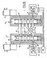
- Valve assemblies 11 and 12 include spools 80 and 81 received in longitudinal bores 82 and 83 of valve bodies 84 and 85, respectively.
- the valve assemblies are comprised of 5 port, 2 position valves (5/2-way valves) having inlet ports 86 and 87, outlet ports 88 and 89, exhaust ports 90 and 91, first cross-mirror ports 92 and 93, and second cross-mirror ports 94 and 95, respectively.
- the ports of the first and second unitary valve assemblies are interconnected by passages 40 and 54-57 as shown.
- the first and second plates for implementing these passages are not explicitly shown in order to simply the drawings.
- Inlet passage 57, outlet passage 40, and exhaust passage 54 include external ports as shown so that the equivalent of a 3/2-way valve is achieved by the interconnection of the two 5/2-way valves.
- Pressurized fluid at first cross-mirror ports 92 and 93 is provided to respective inlets of pilot valves 13 and 14 via passages 96 and 97 through flow restricters 98 and 99.
- Return springs 100 and 101 urge spools 80 and 81 into their upward deactuated positions as shown in Figure 3.
- the areas within bores 82 and 83 beneath spools 80 and 81 are coupled to atmosphere via passages 102 and 103, respectively.
- outlet passage 40 is coupled to exhaust passage 54 through both valve assemblies 11 and 12.
- Inlet 57 is coupled to second cross-mirror ports 94 and 95 through both valve assemblies 11 and 12 and the cross connection of the cross-mirror ports provides the inlet pressure to first cross-mirror ports 92 and 93. Consequently, passages 96 and 97 are pressurized so that actuation of pilot valves 13 and 14 can move spools 80 and 81 to their actuated positions as shown in Figure 4.
- inlet pressure at ports 86 and 87 flows to first cross-mirror ports 92 and 93, through the cross-connection to second cross-mirror ports 94 and 95 and through bores 82 and 83 to outlet ports 88 and 89.
- Figure 5 shows double valve 10 in a faulted position wherein one valve assembly is in its deactuated position and the other valve assembly is in its actuated position.
- outlet ports 88 and 89 are coupled to exhaust ports 90 and 91 so that the outlet cannot become pressurized.
- the valve assembly which is in its deactuated position i.e., valve assembly 11 in Figure 5
- the valve assembly in its deactuated position couples outlet passage 40 to exhaust passage 54.
- the valve assembly in its actuated position couples outlet passage 40 to the cross connection passage 55, thereby depressurizing the first cross-mirror port of the valve assembly in its deactuated position.
- Figures 6-9 show schematic representations of the pneumatic circuits of the double valve of the present invention in a deactuated position, an actuated position, and a faulted position of the double valve, respectively.
- a first embodiment is shown in Figures 9-11 including a pair of pressure switches 110 and 111 coupled to sensing ports 78 and 79 which lead to passages 112 and 113 and to first cross-mirror ports 92 and 93 through flow restricters 98 and 99, respectively.
- Pressure switches 110 and 111 are coupled via signal lines 114 and 115 to a control monitor circuit 116.
- An interconnection between the signal lines is controlled by a switch element 117 and 118, which may be actuated by pressurized fluid against springs 119 and 120 in pressure switches 110 and 111, respectively.
- pressure switches 110 and 111 are configured as failure indicators to monitor proper valve operation.
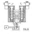
- FIG. 12-14 An alternative embodiment for monitoring the valve state is shown in Figures 12-14.
- An AND-gate 126 has a pair of inlets coupled by passages 121 and 122 to cross-connection passages 55 and 56, respectively.
- the outlet of AND-gate 126 is coupled to a pressure switch 123.
- pressure from AND-gate 126 pushes a switch element 124 against spring 125, thereby actuating pressure switch 123 and supplying a corresponding signal to control monitor circuit 116.
- Figures 12 and 13 illustrate pressure switch 123 being actuated with the double valve in its deactuated and actuated positions, respectively.
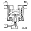
- Figure 14 shows the double valve in a faulted state with first unitary valve assembly 11 in its deactuated position and second unitary valve assembly 12 in its actuated position.
- Cross-connection passage 55 is not pressurized while cross-connection passage 56 is pressurized.
- the unequal pressures supplied to AND-gate 126 causes the outlet of AND-gate 126 to become unpressurized.
- Pressure switch 123 is deactuated by spring 125 and a corresponding signal is provided to control monitor circuit 116.
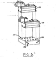
- FIG. 1 and 2 utilizes a standard in-line valve type.
- Figure 15 shows an alternative embodiment utilizing base-mounted unitary valve assemblies 130 and 131.
- a plate 132 receives valve assemblies 130 and 131 and includes ports 134 on an upper surface thereof for interfacing with the ports of valve assemblies 130 and 131.
- Plate 132 includes ports 135 on an adjacent face to provide a corresponding inlet ports, outlet ports, exhaust ports, and sensing ports for the double valve of the present invention.
- valves Although the present invention has been illustrated with in-line and base-mounted valves, other types of valves or combination of valves may be utilized in the present invention.
Landscapes
- Engineering & Computer Science (AREA)
- General Engineering & Computer Science (AREA)
- Mechanical Engineering (AREA)
- Chemical & Material Sciences (AREA)
- Analytical Chemistry (AREA)
- Physics & Mathematics (AREA)
- Fluid Mechanics (AREA)
- Multiple-Way Valves (AREA)
- Valve Housings (AREA)
- Fluid-Pressure Circuits (AREA)
- Fluid-Driven Valves (AREA)
Description
- The present invention relates in general to control valves, and, more specifically, to a double valve constructed from a pair a single-valve assemblies.
- Pneumatically-powered machine tools of various types operate through a valving system which interacts with a pneumatically-controlled clutch and/or brake assembly. For safety reasons, the control valves that are used to operate these machine tools require the operator to activate two separate control switches substantially simultaneously to ensure that an operator's hands are away from the moving components of the machine tool when an operating cycle is initiated. Typically, an electronic circuit responsive to the two control switches generates a pilot control signal applied to the pilot valves for switching the main fluid circuit of the valve to control delivery of compressed air (or other fluid) to the machine tool to perform its operating cycle.
- Double valves operating in parallel in one valve body have been developed to ensure that a repeat or overrun of a machine tool operating cycle cannot be caused by malfunction of a single valve unit (e.g., a valve becoming stuck in an actuated position). Thus, if one valve unit fails to deactuate at the proper time, the double valve assumes a configuration that diverts the source of compressed air from the machine tool. A double valve is shown, for example, in commonly assigned
U.S. patent 6,478,049 to Bento et al . - From
US-A-3 108 612 a double valve is known which is comprising: - first and second valve each having a respective inlet port, a respective outlet port, a respective exhaust port, a respective first cross-mirror port, and a respective second cross-mirror port;
- first and second pilot assemblies coupled to said first and second valves respectively;
- a first plate coupled to said first and second valves including respective passages to provide a common inlet port coupled to said respective inlet ports of said and second valves and a common outlet port coupled to said respective outlet ports of said first and second valves
- a second plate coupled to said first and second valves providing a first cross-connection between said first cross-mirror port of said first valve and said second cross-mirror port of said second valve and providing a second cross-connection between said second cross-mirror port of said first valve and said first cross-mirror port of said second valve.
- In a typical double valve, two movable valve units are mounted within respective bores within a single valve body or block. Each movable valve unit has a respective exhaust poppet between the outlet port and the exhaust port of the double valve and a respective inlet poppet between the outlet port and the inlet port of the double valve. Pilot valves are moved to an actuated position in response to an electrical control signal from a respective operator-controlled switch, which typically causes the exhaust poppets to close and the inlet poppets to open. Any time that 1) a valve unit fails to deactuate properly, 2) a valve unit fails to actuate properly, or 3) the pilot valves are actuated or deactuated non-simultaneously, then at least one valve unit becomes locked in a faulted position where its exhaust poppet cannot be closed (thereby preventing the outlet from becoming pressurized).
- In addition to providing protection against the repeat or overrun of the machine tool, it is desirable to monitor the double valve for a faulted valve unit and to prevent a new operating cycle of the machine tool from being initiated. Thus, prior art systems have caused the double valve to assume a lock-out configuration when a single valve unit is in a faulted condition so that the double valve cannot again be actuated until it has been intentionally reset to clear the faulted condition.
- The structure of an integrated double valve is relatively more complicated than that of a single poppet type valve. Consequently, the material costs and manufacturing costs of a double valve are higher. It would be desirable to achieve the safety functionality of a double valve (e.g., a locked out fault position and a monitoring capability) while avoiding the corresponding higher costs.
- The present invention has the advantage of constructing a double valve at low cost without a complex manufacturing operation. A pair of single unitary valve assemblies are built into a double valve assembly in such a way that the safety functionality of a double valve is obtained.
- In one aspect of the invention, a double valve comprises first and second unitary valve assemblies each having a respective inlet port, a respective outlet port, a respective exhaust port, a respective first cross-mirror port, and a respective second cross-mirror port. First and second pilot assemblies are coupled to the first and second unitary valve assemblies, respectively. A first plate is coupled to the first and second unitary valve assemblies and includes respective passages to provide a common inlet port coupled to the respective inlet ports of the first and second unitary valve assemblies, a common outlet port coupled to the respective outlet ports of the first and second unitary valve assemblies. A second plate is coupled to the first and second unitary valve assemblies providing a first cross-connection between the first cross-mirror port of the first unitary valve assembly and the second cross-mirror port of the second unitary valve assembly, and providing a second cross-connection between the second cross-mirror port of the first unitary valve assembly and the first cross-mirror port of the second unitary valve assembly, and including a common exhaust port coupled to the respective exhaust ports of the first and second unitary valve assemblies.
-
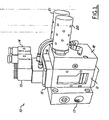
- Figure 1 is a perspective view of a double valve according to one embodiment of the invention.
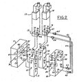
- Figure 2 is an exploded, perspective view of the double valve of Figure 1.
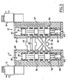
- Figure 3 is a side cross-sectional view of the unitary valve assemblies in an initial, deactuated position.
- Figure 4 is a side cross-sectional view of the unitary valve assemblies in an actuated position.
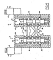
- Figure 5 is a side cross-sectional view of the unitary valve assemblies in a faulted position.
- Figures 6-8 are pneumatic circuit diagrams showing the unitary valve assemblies in a deactuated position, an actuated position, and a faulted position, respectively.
- Figure 9 is a side cross-sectional view of the double valve of the present invention in a deactuated position and incorporating pressure switches to be used as a failure indicator.
- Figure 10 is a side cross-sectional view of the double valve in Figure 9 in an actuated position.
- Figure 11 is a side cross-sectional view of the double valve of Figure 9 in a faulted position.
- Figure 12 is a side cross-sectional view of an alternative embodiment of a double valve including a pressure switch used as a failure indicator.
- Figure 13 is a side cross-sectional view of the double valve of Figure 12 in an actuated position.
- Figure 14 is a side cross-sectional view of the double valve of Figure 12 in a faulted position.
- Figure 15 is an exploded, perspective view of a double valve constructed from base-mounted unitary valve assemblies.
- Referring to Figures 1 and 2, a
double valve 10 is shown comprising a first unitary valve assembly 11 and a secondunitary valve assembly 12. The unitary valve assemblies are preferably comprised of standard single valves such as valve assemblies having part numbers SF6103-IP available from Yonwoo Pneumatic Company. A pair ofsolenoid valves valve assemblies 11 and 12 byadapter blocks second plate 18 is coupled to first and secondunitary valve assemblies 11 and 12 at the opposite side thereof. A pair ofexhaust silencers second plate 18 in order to muffle noise at the exhaust ports. First unitary valve assembly 11 includes aninlet port 22, an outlet port 23, afirst cross-mirror port 24, asecond cross-mirror port 25, and anexhaust port 26. Secondunitary valve assembly 12 includes aninlet port 27, an outlet port 28, afirst cross-mirror port 30, asecond cross-mirror port 31, and anexhaust port 32. - First and second unitary valve assemblies 11 and 12 preferably comprise 5/2 way valves as is known in the art. After incorporation into the double valve of the present invention, a 3/2 way valve results.
-
Inlet ports ports ports passage 35, andexternal inlet ports unitary valve assemblies 11 and 12. Specifically,ports passage 40 extending through first plate 17 betweenexternal outlet ports 41 and 42. By providing two inlet ports and two outlet ports on first plate 17, one port can be used as a working port while the second can be used as a sensing port. For example, a pressure switch or a pressure transducer can be used to monitor the outlet pressure at the sensing outlet port. -
Second plate 18 includes various internal passages for coupling with first and secondunitary valve assemblies 11 and 12. A first cross-connection includesports 45 and 48 interconnected by apassage 55 for cross connectingfirst cross-mirror port 24 of first unitary valve assembly 11 withsecond cross-mirror port 31 of secondunitary valve assembly 12. A second cross connection includes ports 46 and 47 interconnected by apassage 56 so thatsecond cross-mirror port 25 of first unitary valve assembly 11 is connected withfirst cross-mirror port 30 of secondunitary valve assembly 12.Second plate 18 further includes an exhaust circuit for interconnectingexhaust ports unitary valve assemblies 11 and 12. Thus,ports ports internal passages 54.Ports exhaust ports unitary valve assemblies 11 and 12.Exhaust ports second plate 18 are preferably coupled tosilencers -
Second plate 18 includespilot ports cross-connection passages tubes solenoid pilot valves elbow connections ports Fittings connections Connections passages 70 and 71 for supplying a source of pilot pressure to standard inlets insolenoid pilot valves pilot supply ports unitary valve assemblies 11 and 12. A pair ofpassages solenoid valves passages 76 and 77 of first and secondunitary valve assemblies 11 and 12 in order to actuate the respective valves when the corresponding solenoid pilot valves are actuated by one or more electrical switches (not shown) and are being supplied with a source of pressurized fluid. In an alternative embodiment, pilot connections for supplying pilot pressure to the pilot valves can be comprised of internal passages within the bodies ofvalve assemblies 11 and 12 and/or withinplate 18, instead of using external tubings. -
Second plate 18 further includessensing ports cross passages - Basic operation of the double valve of the present invention will now be described with reference to Figures 3-5.
Valve assemblies 11 and 12 includespools longitudinal bores valve bodies inlet ports outlet ports exhaust ports cross-mirror ports cross-mirror ports passages 40 and 54-57 as shown. The first and second plates for implementing these passages are not explicitly shown in order to simply the drawings.Inlet passage 57,outlet passage 40, andexhaust passage 54 include external ports as shown so that the equivalent of a 3/2-way valve is achieved by the interconnection of the two 5/2-way valves. - Pressurized fluid at first
cross-mirror ports pilot valves passages bores spools passages - In the deactuated position shown in Figure 3,
outlet passage 40 is coupled toexhaust passage 54 through bothvalve assemblies 11 and 12.Inlet 57 is coupled to secondcross-mirror ports valve assemblies 11 and 12 and the cross connection of the cross-mirror ports provides the inlet pressure to firstcross-mirror ports passages pilot valves spools spools ports cross-mirror ports cross-mirror ports bores outlet ports - Figure 5 shows
double valve 10 in a faulted position wherein one valve assembly is in its deactuated position and the other valve assembly is in its actuated position. In the faulted position or state,outlet ports exhaust ports outlet passage 40 toexhaust passage 54. Also at that time, the valve assembly in its actuated position couplesoutlet passage 40 to thecross connection passage 55, thereby depressurizing the first cross-mirror port of the valve assembly in its deactuated position. Consequently, no pressure is provided to the pilot valve of the deactuated valve assembly and the deactuated valve assembly cannot become actuated. Therefore, a pneumatic press or other equipment being operated by the double valve cannot be actuated until the fault in the double valve is corrected. Therefore, the safety function of a double valve is achieved using a low cost solution having unitary valve assemblies integrated into a single structure. - Figures 6-9 show schematic representations of the pneumatic circuits of the double valve of the present invention in a deactuated position, an actuated position, and a faulted position of the double valve, respectively.
- The present invention also provides for monitoring of the faulted/non-faulted state of the valve. A first embodiment is shown in Figures 9-11 including a pair of pressure switches 110 and 111 coupled to sensing
ports passages cross-mirror ports signal lines control monitor circuit 116. An interconnection between the signal lines is controlled by aswitch element springs passages cross-mirror ports switches 110 and 111 actuates theswitch elements springs monitor circuit 116, signifying proper operation of the double valve. Figure 10 illustrates how pressure is supplied to both pressure switches 110 and 111 with the double valve in its actuated position. - When the double valve is in a faulted position as shown in Figure 11, pressure to one of the pilot passages from the corresponding cross-mirror port drops to atmospheric pressure. Consequently, the corresponding switch (i.e.,
pressure switch 110 in Figure 11) is no longer actuated against its spring and the switch element completes a circuit with the opposite contact thereby signifying that the double valve is in a faulted state. - An alternative embodiment for monitoring the valve state is shown in Figures 12-14. An AND-gate 126 has a pair of inlets coupled by
passages cross-connection passages AND-gate 126 is coupled to apressure switch 123. There is pressure in the outlet ofAND-gate 126 only when both inlets to AND-gate 126 are pressurized. Both inlets are pressurized whenever the double valve has not entered a faulted position. When the double valve is in a proper actuated or deactuated state, pressure fromAND-gate 126 pushes aswitch element 124 againstspring 125, thereby actuatingpressure switch 123 and supplying a corresponding signal to controlmonitor circuit 116. Figures 12 and 13 illustratepressure switch 123 being actuated with the double valve in its deactuated and actuated positions, respectively. - Figure 14 shows the double valve in a faulted state with first unitary valve assembly 11 in its deactuated position and second
unitary valve assembly 12 in its actuated position.Cross-connection passage 55 is not pressurized whilecross-connection passage 56 is pressurized. The unequal pressures supplied toAND-gate 126 causes the outlet ofAND-gate 126 to become unpressurized.Pressure switch 123 is deactuated byspring 125 and a corresponding signal is provided to controlmonitor circuit 116. - The valve construction shown in Figures 1 and 2 utilizes a standard in-line valve type. Figure 15 shows an alternative embodiment utilizing base-mounted
unitary valve assemblies plate 132 receivesvalve assemblies ports 134 on an upper surface thereof for interfacing with the ports ofvalve assemblies Plate 132 includesports 135 on an adjacent face to provide a corresponding inlet ports, outlet ports, exhaust ports, and sensing ports for the double valve of the present invention. - Although the present invention has been illustrated with in-line and base-mounted valves, other types of valves or combination of valves may be utilized in the present invention.
Claims (9)
- A double valve comprising:first and second unitary valve assemblies (11, 12) each having a unitary valve body and each having a respective inlet port, (22, 27) a respective outlet port (23, 28), a respective exhaust port (26, 32), a respective first cross-mirror port (24, 30), and a respective second cross-mirror port (25, 31);first and second pilot assemblies (13, 14) coupled to said first and second unitary valve assemblies, respectively ;a first plate (17) coupled to said first and second unitary valve assemblies including respective passages to provide a common inlet port (36, 37) coupled to said respective inlet ports of said first and second unitary valve assemblies and a common outlet port (41, 42) coupled to said respective outlet ports of said first and second unitary valve assemblies;a second plate (18) coupled to said first and second unitary valve assemblies providing a first cross-connection between said first cross-mirror port (24) of said first unitary valve assembly (11) and said second cross-mirror port (31) of said second unitary valve assembly (12), and providing a second cross-connection between said second cross-mirror port (25) of said first unitary valve assembly (11) and said first cross-mirror port (30) of said second unitary valve assembly (12), and including a common exhaust port (52, 53) coupled to said respective exhaust ports (26, 32) of said first and second unitary valve assemblies.
- The double valve of claim 1 wherein said second plate further provides first and second pressure monitoring passages (112, 113) coupled to said first and second cross-connections, respectively.
- The double valve of claim 2 further comprising first and second pressure switches (110, 111) coupled to said first and second pressure monitoring passages, respectively.
- The double valve of claim 3 further comprising first and second flow restrictors (98, 99) coupled between said first and second pressure switches and said first cross-connections of said first and second unitary valve assemblies, respectively.
- The double valve of claim 2 further comprising:an AND-gate (126) having input ports coupled to said first and second pressure monitoring passages, respectively, and having an output port which is pressurized when both of said input ports receive a pressure greater than or equal to a predetermined pressure; anda pressure switch (123) coupled to said output port of said AND-gate for indicating whether said output port is pressurized.
- The double valve of claim 1 further comprising:first and second pilot passages (96, 97) supplying pressurized fluid from said first cross-mirror ports of said first and second unitary valve assemblies, respectively, to said first and second pilot assemblies, respectively.
- The double valve of claim 6 wherein said first and second pilot passages are comprised of first and second tubing pieces, respectively, wherein said double valve further comprises first and second pilot plates coupling said first and second pilot assemblies with said first and second unitary valve assemblies, respectively, and wherein said first and second tubing pieces are coupled between said second plate and said first and second pilot plates.
- The double valve of claim 1 wherein said first and second unitary valve assemblies are comprised of in-line valves.
- The double valve of claim 1 wherein said first and second unitary valve assemblies are comprised of base-mounted valves having bases conforming to standard dimensions.
Applications Claiming Priority (4)
| Application Number | Priority Date | Filing Date | Title |
|---|---|---|---|
| US49966703P | 2003-09-03 | 2003-09-03 | |
| US499667P | 2003-09-03 | ||
| US10/718,245 US7114521B2 (en) | 2003-09-03 | 2003-11-20 | Double valve constructed from unitary single valves |
| US718245 | 2003-11-20 |
Publications (3)
| Publication Number | Publication Date |
|---|---|
| EP1512873A2 EP1512873A2 (en) | 2005-03-09 |
| EP1512873A3 EP1512873A3 (en) | 2005-08-03 |
| EP1512873B1 true EP1512873B1 (en) | 2007-06-13 |
Family
ID=34139055
Family Applications (1)
| Application Number | Title | Priority Date | Filing Date |
|---|---|---|---|
| EP20040255307 Expired - Lifetime EP1512873B1 (en) | 2003-09-03 | 2004-09-02 | Double valve constructed from unitary single valves |
Country Status (7)
| Country | Link |
|---|---|
| US (1) | US7114521B2 (en) |
| EP (1) | EP1512873B1 (en) |
| JP (1) | JP4744114B2 (en) |
| CN (1) | CN100378347C (en) |
| BR (1) | BRPI0403726B1 (en) |
| DE (1) | DE602004006928T2 (en) |
| ES (1) | ES2285366T3 (en) |
Families Citing this family (10)
| Publication number | Priority date | Publication date | Assignee | Title |
|---|---|---|---|---|
| US7481149B2 (en) * | 2005-07-04 | 2009-01-27 | Smc Corporation | Bimanual control valve |
| US8028717B2 (en) * | 2007-10-04 | 2011-10-04 | Ross Operating Valve Company | High throughput double valve with reduced outlet pressure during a faulted state |
| CN101659131B (en) * | 2009-09-18 | 2011-11-30 | 无锡市拓发自控设备有限公司 | Safety control double-valve for power-off protection type press machine |
| US8794123B2 (en) * | 2010-03-12 | 2014-08-05 | Ross Operating Valve Company | Double valve constructed from unitary single valves |
| CN102878325A (en) * | 2012-10-18 | 2013-01-16 | 无锡市拓发自控设备有限公司 | Two-position three-way electromagnetic valve of combination pneumatic swivel joint |
| US9945494B2 (en) * | 2013-06-04 | 2018-04-17 | Spx Flow, Inc. | Pneumatic directional valve and method of operation |
| CN106415094B (en) * | 2014-06-20 | 2019-05-07 | 阿斯科公司 | Zone Manifold Assemblies for Solenoid Valve Control Systems |
| CN104879549A (en) * | 2015-04-10 | 2015-09-02 | 孟书芳 | Multi-head-control high-sensitive air valve |
| CN106090331B (en) * | 2016-07-30 | 2018-10-30 | 杭州鼎隆自动化设备有限公司 | A kind of two-way electromagnetic valve |
| JP7148323B2 (en) * | 2018-08-24 | 2022-10-05 | アズビルTaco株式会社 | CROSS-FLOW TYPE DUAL VALVE AND METHOD FOR MANUFACTURING CASING OF CROSS-FLOW TYPE DUAL VALVE |
Family Cites Families (26)
| Publication number | Priority date | Publication date | Assignee | Title |
|---|---|---|---|---|
| US2906246A (en) | 1953-06-18 | 1959-09-29 | Ross Operating Valve Co | Control system for fluid actuated devices |
| US3068897A (en) * | 1958-11-27 | 1962-12-18 | Erich Herion | Safety control mechanism for pressure circuits |
| US3108612A (en) * | 1959-04-27 | 1963-10-29 | Concordia Masch & Elekt | Valve mechanism for controlling pneumatic or hydraulic apparatus |
| US3051187A (en) * | 1959-10-29 | 1962-08-28 | Walter D Ludwig | Press safety valve |
| DE1273288B (en) * | 1963-12-11 | 1968-07-18 | Concordia Maschinen Und Elek Z | Three-way double valve in safety circuit |
| US3244193A (en) * | 1964-02-24 | 1966-04-05 | Gen Gas Light Co | Multiple valve units |
| US3316930A (en) * | 1964-11-04 | 1967-05-02 | Lawrence H Garduer | Valve |
| CH509535A (en) * | 1970-05-06 | 1971-06-30 | Technomatic Ag | Safety valve for pressure medium operated devices |
| US3848848A (en) * | 1974-03-25 | 1974-11-19 | Tirro D Di | Fail safe apparatus for fluid actuated systems |
| US4100937A (en) * | 1976-08-16 | 1978-07-18 | Owens-Illinois, Inc. | Valve block |
| DD136524A5 (en) * | 1977-12-16 | 1979-07-11 | Technomatic Ag | SAFETY VALVE |
| US4181148A (en) * | 1978-06-23 | 1980-01-01 | Ross Operating Valve Company | Self monitoring double valve |
| US4291613A (en) * | 1979-02-23 | 1981-09-29 | Ross Operating Valve Company | Monitor for double safety valves |
| DE2930571A1 (en) * | 1979-07-27 | 1981-02-12 | Technomatic Ag Aesch | SAFETY VALVE |
| US4257455A (en) | 1979-09-06 | 1981-03-24 | Ross Operating Valve Company | Double safety valve for stamping presses and the like |
| US4359064A (en) * | 1980-07-24 | 1982-11-16 | Kimble Charles W | Fluid power control apparatus |
| US4542767A (en) * | 1983-04-05 | 1985-09-24 | Ross Operating Valve Company | Monitor for double safety valves |
| DE3529802A1 (en) * | 1985-08-20 | 1987-02-26 | Herion Werke Kg | TWO-HANDED SECURITY CONTROL |
| AT391178B (en) * | 1985-12-30 | 1990-08-27 | Enfo Grundlagen Forschungs Ag | 5/3-WAY VALVE UNIT |
| DE19537482A1 (en) * | 1995-10-09 | 1997-04-10 | Schwelm Hans | Hydraulic control block |
| US6478049B2 (en) * | 1996-12-16 | 2002-11-12 | Ross Operating Valve Company | Double valve with anti-tiedown capability |
| US5927324A (en) | 1996-12-16 | 1999-07-27 | Ross Operating Valve Company | Cross flow with crossmirror and lock out capability valve |
| US5850852A (en) * | 1996-12-16 | 1998-12-22 | Ross Operating Valve Company | Crossflow with crossmirror and lock out capability valve |
| BR9702779A (en) | 1997-08-21 | 1999-03-09 | Jose Carlos Bento | Maximum safety double electropneumatic valve for pneumatically operated brake and / or clutch control of mechanical presses |
| DE10112496B4 (en) * | 2001-03-15 | 2004-09-30 | Dbt Gmbh | Valve block for electrohydraulic control device and reusable valves therefor |
| US6604547B1 (en) | 2002-02-19 | 2003-08-12 | Ross Operating Valve Company | Double valve with cross exhaust |
-
2003
- 2003-11-20 US US10/718,245 patent/US7114521B2/en not_active Expired - Lifetime
-
2004
- 2004-09-02 EP EP20040255307 patent/EP1512873B1/en not_active Expired - Lifetime
- 2004-09-02 JP JP2004255808A patent/JP4744114B2/en not_active Expired - Fee Related
- 2004-09-02 BR BRPI0403726-0A patent/BRPI0403726B1/en not_active IP Right Cessation
- 2004-09-02 DE DE200460006928 patent/DE602004006928T2/en not_active Expired - Lifetime
- 2004-09-02 ES ES04255307T patent/ES2285366T3/en not_active Expired - Lifetime
- 2004-09-03 CN CNB2004100855133A patent/CN100378347C/en not_active Expired - Fee Related
Non-Patent Citations (1)
| Title |
|---|
| None * |
Also Published As
| Publication number | Publication date |
|---|---|
| US20050045234A1 (en) | 2005-03-03 |
| JP2005076890A (en) | 2005-03-24 |
| ES2285366T3 (en) | 2007-11-16 |
| EP1512873A2 (en) | 2005-03-09 |
| DE602004006928D1 (en) | 2007-07-26 |
| EP1512873A3 (en) | 2005-08-03 |
| DE602004006928T2 (en) | 2008-02-14 |
| US7114521B2 (en) | 2006-10-03 |
| BRPI0403726A (en) | 2005-06-07 |
| CN1598333A (en) | 2005-03-23 |
| BRPI0403726B1 (en) | 2015-08-04 |
| JP4744114B2 (en) | 2011-08-10 |
| CN100378347C (en) | 2008-04-02 |
Similar Documents
| Publication | Publication Date | Title |
|---|---|---|
| US9651068B2 (en) | Double valve constructed from unitary single valves | |
| EP1512873B1 (en) | Double valve constructed from unitary single valves | |
| JP2007205568A (en) | System for monitoring dynamic hydraulic power of different actuators | |
| JPH0788844B2 (en) | Valve system and device for online valve replacement | |
| CA2220919C (en) | Crossflow with crossmirror and lock out capability valve | |
| US5927324A (en) | Cross flow with crossmirror and lock out capability valve | |
| EP1255047B1 (en) | Double valve with anti-tiedown capability | |
| CN101868633B (en) | High throughput double valve with reduced outlet pressure during a faulted state | |
| EP1515052B1 (en) | Dynamically-monitored double valve with retained memory of valve states | |
| US6604547B1 (en) | Double valve with cross exhaust | |
| US5796571A (en) | Control device for a two-hand control means for controlling presses for instance | |
| US7089957B2 (en) | Redundant valve system | |
| JPH06507467A (en) | Position indicator for hydraulic setting motors | |
| US3584647A (en) | Solenoid pilot dump combination directional control valve | |
| EP0782057B1 (en) | A double valve control device | |
| US6722390B2 (en) | Hydraulic double valve | |
| EP1069323A1 (en) | Cross flow with crossmirror and lock out capability valve |
Legal Events
| Date | Code | Title | Description |
|---|---|---|---|
| PUAI | Public reference made under article 153(3) epc to a published international application that has entered the european phase |
Free format text: ORIGINAL CODE: 0009012 |
|
| AK | Designated contracting states |
Kind code of ref document: A2 Designated state(s): AT BE BG CH CY CZ DE DK EE ES FI FR GB GR HU IE IT LI LU MC NL PL PT RO SE SI SK TR |
|
| AX | Request for extension of the european patent |
Extension state: AL HR LT LV MK |
|
| PUAL | Search report despatched |
Free format text: ORIGINAL CODE: 0009013 |
|
| AK | Designated contracting states |
Kind code of ref document: A3 Designated state(s): AT BE BG CH CY CZ DE DK EE ES FI FR GB GR HU IE IT LI LU MC NL PL PT RO SE SI SK TR |
|
| AX | Request for extension of the european patent |
Extension state: AL HR LT LV MK |
|
| 17P | Request for examination filed |
Effective date: 20060125 |
|
| AKX | Designation fees paid |
Designated state(s): DE ES FR GB IT |
|
| GRAP | Despatch of communication of intention to grant a patent |
Free format text: ORIGINAL CODE: EPIDOSNIGR1 |
|
| GRAJ | Information related to disapproval of communication of intention to grant by the applicant or resumption of examination proceedings by the epo deleted |
Free format text: ORIGINAL CODE: EPIDOSDIGR1 |
|
| GRAP | Despatch of communication of intention to grant a patent |
Free format text: ORIGINAL CODE: EPIDOSNIGR1 |
|
| GRAS | Grant fee paid |
Free format text: ORIGINAL CODE: EPIDOSNIGR3 |
|
| GRAA | (expected) grant |
Free format text: ORIGINAL CODE: 0009210 |
|
| RAP1 | Party data changed (applicant data changed or rights of an application transferred) |
Owner name: ROSS OPERATING VALVE COMPANY |
|
| AK | Designated contracting states |
Kind code of ref document: B1 Designated state(s): DE ES FR GB IT |
|
| REG | Reference to a national code |
Ref country code: GB Ref legal event code: FG4D |
|
| REF | Corresponds to: |
Ref document number: 602004006928 Country of ref document: DE Date of ref document: 20070726 Kind code of ref document: P |
|
| ET | Fr: translation filed | ||
| REG | Reference to a national code |
Ref country code: ES Ref legal event code: FG2A Ref document number: 2285366 Country of ref document: ES Kind code of ref document: T3 |
|
| PLBE | No opposition filed within time limit |
Free format text: ORIGINAL CODE: 0009261 |
|
| STAA | Information on the status of an ep patent application or granted ep patent |
Free format text: STATUS: NO OPPOSITION FILED WITHIN TIME LIMIT |
|
| 26N | No opposition filed |
Effective date: 20080314 |
|
| REG | Reference to a national code |
Ref country code: FR Ref legal event code: PLFP Year of fee payment: 13 |
|
| REG | Reference to a national code |
Ref country code: FR Ref legal event code: PLFP Year of fee payment: 14 |
|
| REG | Reference to a national code |
Ref country code: FR Ref legal event code: PLFP Year of fee payment: 15 |
|
| PGFP | Annual fee paid to national office [announced via postgrant information from national office to epo] |
Ref country code: FR Payment date: 20190711 Year of fee payment: 16 |
|
| PGFP | Annual fee paid to national office [announced via postgrant information from national office to epo] |
Ref country code: GB Payment date: 20190830 Year of fee payment: 16 |
|
| PGFP | Annual fee paid to national office [announced via postgrant information from national office to epo] |
Ref country code: ES Payment date: 20191001 Year of fee payment: 16 |
|
| REG | Reference to a national code |
Ref country code: DE Ref legal event code: R082 Ref document number: 602004006928 Country of ref document: DE Representative=s name: HL KEMPNER PATENTANWAELTE, SOLICITORS (ENGLAND, DE Ref country code: DE Ref legal event code: R082 Ref document number: 602004006928 Country of ref document: DE Representative=s name: HL KEMPNER PATENTANWALT, RECHTSANWALT, SOLICIT, DE |
|
| GBPC | Gb: european patent ceased through non-payment of renewal fee |
Effective date: 20200902 |
|
| PG25 | Lapsed in a contracting state [announced via postgrant information from national office to epo] |
Ref country code: FR Free format text: LAPSE BECAUSE OF NON-PAYMENT OF DUE FEES Effective date: 20200930 |
|
| PG25 | Lapsed in a contracting state [announced via postgrant information from national office to epo] |
Ref country code: GB Free format text: LAPSE BECAUSE OF NON-PAYMENT OF DUE FEES Effective date: 20200902 |
|
| REG | Reference to a national code |
Ref country code: ES Ref legal event code: FD2A Effective date: 20220114 |
|
| PG25 | Lapsed in a contracting state [announced via postgrant information from national office to epo] |
Ref country code: ES Free format text: LAPSE BECAUSE OF NON-PAYMENT OF DUE FEES Effective date: 20200903 |
|
| PGFP | Annual fee paid to national office [announced via postgrant information from national office to epo] |
Ref country code: IT Payment date: 20220811 Year of fee payment: 19 Ref country code: DE Payment date: 20220621 Year of fee payment: 19 |
|
| REG | Reference to a national code |
Ref country code: DE Ref legal event code: R119 Ref document number: 602004006928 Country of ref document: DE |
|
| PG25 | Lapsed in a contracting state [announced via postgrant information from national office to epo] |
Ref country code: DE Free format text: LAPSE BECAUSE OF NON-PAYMENT OF DUE FEES Effective date: 20240403 |
|
| PG25 | Lapsed in a contracting state [announced via postgrant information from national office to epo] |
Ref country code: IT Free format text: LAPSE BECAUSE OF NON-PAYMENT OF DUE FEES Effective date: 20230902 |
|
| PG25 | Lapsed in a contracting state [announced via postgrant information from national office to epo] |
Ref country code: IT Free format text: LAPSE BECAUSE OF NON-PAYMENT OF DUE FEES Effective date: 20230902 |