EP1515052B1 - Dynamically-monitored double valve with retained memory of valve states - Google Patents
Dynamically-monitored double valve with retained memory of valve states Download PDFInfo
- Publication number
- EP1515052B1 EP1515052B1 EP20040255062 EP04255062A EP1515052B1 EP 1515052 B1 EP1515052 B1 EP 1515052B1 EP 20040255062 EP20040255062 EP 20040255062 EP 04255062 A EP04255062 A EP 04255062A EP 1515052 B1 EP1515052 B1 EP 1515052B1
- Authority
- EP
- European Patent Office
- Prior art keywords
- inlet
- poppet
- movable
- movable valve
- exhaust
- Prior art date
- Legal status (The legal status is an assumption and is not a legal conclusion. Google has not performed a legal analysis and makes no representation as to the accuracy of the status listed.)
- Expired - Lifetime
Links
- 230000000717 retained effect Effects 0.000 title claims description 6
- 239000012530 fluid Substances 0.000 claims description 37
- 230000008878 coupling Effects 0.000 claims description 10
- 238000010168 coupling process Methods 0.000 claims description 10
- 238000005859 coupling reaction Methods 0.000 claims description 10
- 230000004044 response Effects 0.000 claims description 7
- 238000000034 method Methods 0.000 claims description 5
- 230000005484 gravity Effects 0.000 claims description 3
- 125000006850 spacer group Chemical group 0.000 description 8
- 230000001351 cycling effect Effects 0.000 description 6
- 230000007704 transition Effects 0.000 description 5
- 238000004891 communication Methods 0.000 description 4
- 230000007257 malfunction Effects 0.000 description 2
- 230000009471 action Effects 0.000 description 1
- 230000004913 activation Effects 0.000 description 1
- 230000008901 benefit Effects 0.000 description 1
- 238000010586 diagram Methods 0.000 description 1
- 230000006870 function Effects 0.000 description 1
- 238000012423 maintenance Methods 0.000 description 1
- 238000004519 manufacturing process Methods 0.000 description 1
- 238000003825 pressing Methods 0.000 description 1
- 230000000630 rising effect Effects 0.000 description 1
Images


Classifications
-
- F—MECHANICAL ENGINEERING; LIGHTING; HEATING; WEAPONS; BLASTING
- F15—FLUID-PRESSURE ACTUATORS; HYDRAULICS OR PNEUMATICS IN GENERAL
- F15B—SYSTEMS ACTING BY MEANS OF FLUIDS IN GENERAL; FLUID-PRESSURE ACTUATORS, e.g. SERVOMOTORS; DETAILS OF FLUID-PRESSURE SYSTEMS, NOT OTHERWISE PROVIDED FOR
- F15B20/00—Safety arrangements for fluid actuator systems; Applications of safety devices in fluid actuator systems; Emergency measures for fluid actuator systems
- F15B20/001—Double valve requiring the use of both hands simultaneously
-
- Y—GENERAL TAGGING OF NEW TECHNOLOGICAL DEVELOPMENTS; GENERAL TAGGING OF CROSS-SECTIONAL TECHNOLOGIES SPANNING OVER SEVERAL SECTIONS OF THE IPC; TECHNICAL SUBJECTS COVERED BY FORMER USPC CROSS-REFERENCE ART COLLECTIONS [XRACs] AND DIGESTS
- Y10—TECHNICAL SUBJECTS COVERED BY FORMER USPC
- Y10T—TECHNICAL SUBJECTS COVERED BY FORMER US CLASSIFICATION
- Y10T137/00—Fluid handling
- Y10T137/0318—Processes
- Y10T137/0396—Involving pressure control
-
- Y—GENERAL TAGGING OF NEW TECHNOLOGICAL DEVELOPMENTS; GENERAL TAGGING OF CROSS-SECTIONAL TECHNOLOGIES SPANNING OVER SEVERAL SECTIONS OF THE IPC; TECHNICAL SUBJECTS COVERED BY FORMER USPC CROSS-REFERENCE ART COLLECTIONS [XRACs] AND DIGESTS
- Y10—TECHNICAL SUBJECTS COVERED BY FORMER USPC
- Y10T—TECHNICAL SUBJECTS COVERED BY FORMER US CLASSIFICATION
- Y10T137/00—Fluid handling
- Y10T137/8593—Systems
- Y10T137/87169—Supply and exhaust
- Y10T137/87193—Pilot-actuated
- Y10T137/87209—Electric
Definitions
- the present invention relates in general to control valves, and, more specifically, to a double valve for controlling a single flow of pressurized fluid in response to simultaneous activation of a pair of control switches.
- Machine tools of various types operate through a valving system, which interacts with a pneumatically-controlled clutch and/or brake assembly.
- the control valves that are used to operate these machine tools require the operator to activate two separate control switches substantially simultaneously to ensure that an operator's hands are away from the moving components of the machine tool when an operating cycle is initiated.
- an electronic circuit responsive to the two control switches generates a pilot control signal applied to the pilot valves for switching the main fluid circuit of the valve to control delivery of compressed air (or other fluid) to the machine tool to perform its operating cycle.
- Double valves operating in parallel in one valve body have been developed to ensure that a repeat or overrun of a machine tool operating cycle cannot be caused by malfunction of a single valve unit (e.g., a valve becoming stuck in an actuated position). Thus, if one valve unit fails to deactuate at the proper time, the double valve assumes a configuration that diverts the source of compressed air from the machine tool.
- a double valve is shown, for example, in commonly assigned U.S. patent 6,478,049 to Bento et al , which is incorporated herein by reference for all purposes.
- a double valve assembly includes two electromagnetically-controlled pilot valves.
- the pilot valves are normally closed.
- the double valve assembly includes two movable valve units, each with a respective exhaust poppet between the outlet port and the exhaust port of the double valve and a respective inlet poppet between the outlet port and the inlet port of the double valve.
- the pilot valves are normally closed, then the exhaust poppets are normally open and the inlet poppets are normally closed.
- Each of the pilot valves is moved to an actuated position in response to an electrical control signal from a respective operator-controlled switch, which typically causes the exhaust poppets to close and the inlet poppets to open.
- the inlet to the double valve receives a continuous source of pressurized fluid.
- the source is periodically turned off (e.g., during maintenance or at the end of a work shift).
- pressures within different sections of the double valve acting upon various valve components decays and then rebuilds, thereby causing forces on the valve units not typically experienced during normal running conditions.
- the affect upon the movable valve units of cycling the pressure has typically been inconsistent and unpredictable.
- a valve unit that was in a faulted state can end up being reset by the pressure cycling. This is undesirable because the failure of a valve that becomes faulted shortly before cycling the pressure might not be noticed before the pressure is turned off.
- EP 1255047 discloses a control valve system comprising first and second pluralities of valves, each plurality of valves being moveable between an actuated position, a deactuated position and an intermediate position.
- a plurality of reset members are selectively engageable with the first plurality of valves.
- the present invention seeks to provide a double valve with memory such that when the valve is in its normal deactuated state and the inlet air supply is cycled (e.g., turned from on to off or from off to on), then the valve remains in the deactuated (i.e., ready to run) state.
- the valve is in a faulted state (e.g., intermediate position) and the inlet air supply is cycled, then the valve remains in the faulted state.
- the memory is achieved by a balanced condition of the movable valve elements when in the normal deactuated position and an unbalanced or latched condition when in the intermediate or faulted position.
- control valve system comprises a housing defining an inlet; an outlet and an exhaust, wherein the inlet is adapted to receive pressurized fluid.
- a first movable valve unit includes a first exhaust poppet and a first inlet poppet, wherein the first exhaust poppet is movable between an open position for coupling the outlet to the exhaust and a closed position for isolating the outlet from the exhaust, and wherein the first inlet poppet is movable between an open position for coupling the outlet to the inlet and a closed position for isolating the outlet from the inlet.
- the first movable valve unit is movable to an actuated position, a deactuated position, and an intermediate position, wherein the actuated position comprises the first inlet poppet being in its open position and the first exhaust poppet being in its closed position, wherein the deactuated position comprises the first inlet poppet being in its closed position and the first exhaust poppet being in its open position, and wherein the intermediate position comprises the first inlet poppet and the first exhaust poppet both being at least partially open.
- a second movable valve unit includes a second exhaust poppet and a second inlet poppet, wherein the second exhaust poppet is movable between an open position for coupling the outlet to the exhaust and a closed position for isolating the outlet from the exhaust, and wherein the second inlet poppet is movable between an open position for coupling the outlet to the inlet and a closed position for isolating the outlet from the inlet.
- the second movable valve unit is movable to an actuated position, a deactuated position, and an intermediate position, wherein the actuated position comprises the second inlet poppet being in its open position and the second exhaust poppet being in its closed position, wherein the deactuated position comprises the second inlet poppet being in its closed position and the second exhaust poppet being in its open position, and wherein the intermediate position comprises the second inlet poppet and the second exhaust poppet both being at least partially open.
- First and second crossover chambers communicate with the second and first inlet poppets, respectively.
- First and second flow restrictors couple the inlet to the first and second crossover chambers, respectively.
- First and second pilot valves are disposed at one end of the first and second movable valve units, respectively, for selectably urging the first and second movable valve units to the respective actuated positions.
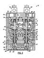
- a control valve system in the form of a double valve 10 includes a housing 11 having an inlet port 12 leading to an inlet chamber 13, an outlet port 14 leading to an outlet chamber 15, and an exhaust port 16 leading to an exhaust chamber 17.
- Housing 11 may include separate blocks 11a - 11d which may be clamped or bolted together.
- Chambers 13, 15, and 17 are joined by various passages to create elongated bores for receiving a first movable valve unit 18 and a second movable valve unit 20.
- First movable valve unit 18 includes an exhaust piston/piston/poppet 21 slidably received at one end of a stem 22 via a piston 23.
- First movable valve unit 18 also includes an inlet poppet 24 and a flow restrictor 25.
- a disk-shaped shoulder 26 extends from a spacer 34 that is fixed to stem 22. Shoulder 26 is slidably received in a passage 27 forming flow restrictor 25 so that pressurized fluid from inlet chamber 13 flows at a reduced rate into a first crossover chamber 28 when shoulder 26 is present in passage 27.
- stem 22 receives pistons 30 and 31 which are retained by a retainer nut 33 threaded to one end of stem 22. Pistons 30 and 31 are slidably received in a bushing 32 which is rigidly retained within housing 11.
- a spring stop 36 is slidably received on spacer 34 and is urged in an upward direction by a return spring 35.
- Beneath movable valve unit 18, a return chamber 37 is formed which receives part of a reset piston 38 and a piston return spring 40.
- First movable valve unit 18 is shown in Figure 1 in its deactuated position wherein outlet port 14 is open to exhaust port 16 and closed to inlet port 12.
- exhaust piston/poppet 21 is in its upward, deactuated position wherein an exhaust seal 42 is spaced away from an exhaust seat 41.
- an inlet seal 44 of inlet poppet 24 is disposed against an inlet seat 43.
- Second movable valve unit 20 includes an exhaust piston/poppet 46 slidably received at one end of a stem 47 via a piston 48. Second movable valve unit 20 also includes an inlet poppet 50 and a flow restrictor 51. A disk-shaped shoulder 52 extends from a spacer 60 that is fixed to stem 47. Shoulder 52 is slidably received in a passage 53 forming flow restrictor 51 so that pressurized fluid from inlet chamber 13 flows at a reduced rate into a second crossover chamber 54 when shoulder 52 is present in passage 53.
- stem 47 receives pistons 55 and 56 which are retained by a retainer nut 58 threaded to one end of stem 47. Pistons 55 and 56 are slidably received in a bushing 57 which is rigidly retained within housing 11.
- a spring stop 62 is slidably received on spacer 60 and is urged in an upward direction by a return spring 61.
- Beneath movable valve unit 20, a return chamber 63 is formed which receives part of a reset piston 64 and a piston return spring 65.
- Second movable valve unit 20 is shown in Figure 1 in its deactuated position wherein outlet port 14 is open to exhaust port 16 and closed to inlet port 12.
- exhaust piston/poppet 46 is in its upward, deactuated position wherein an exhaust seal 67 is spaced away from an exhaust seat 66.
- an inlet seal 70 of inlet poppet 50 is disposed against an inlet seat 68.
- a fluid passage 72 provides fluid communication between first crossover chamber 28 and return chamber 63 of second movable valve unit 20.
- a fluid passage 73 provides fluid communication from first crossover chamber 28 to timing chambers 74 and 75 for providing pressurized fluid to an input of a first pilot valve 76.
- a passage 77 is coupled between the output of first pilot valve 76 and the upper surface of exhaust piston/poppet 21.
- a fluid passage 78 provides fluid communication between second crossover chamber 54 and return chamber 37 of first movable valve unit 18.
- a fluid passage 80 provides fluid communication from second crossover chamber 54 to timing chambers 81 and 82 for providing pressurized fluid to an input of a second pilot valve 83.
- a passage 84 is coupled between the output of second pilot valve 83 and the upper surface of exhaust piston/poppet 46.
- a reset port 85 communicates with a reset passage 86 for providing reset pressure to reset pistons 38 and 64 which extend upward to put first and second movable valve units 18 and 20 in their normal deactuated positions.
- valve units 18 and 20 are held in their upper, deactuated positions by friction (e.g., between pistons 30 and 31 and bushing 32).
- the amount of friction provided is sufficient to maintain the movable valve units in their current positions against the force of gravity regardless of what orientation the valve body is placed.
- first movable valve unit 18 that are open to inlet chamber 13 include a first side 87 of shoulder 26 and an upper surface 89 of piston 30. These surfaces are provided with equal areas such that inlet pressure against the surfaces creates an upward force against surface 87 which is substantially exactly counterbalanced by a downward force against surface 89.
- a surface 88 of shoulder 52 has an area substantially equal to a surface 90 of piston 55.
- crossover chambers 28 and 54 Due to the imperfect seals of flow restrictors 25 and 51, pressure begins to build up in crossover chambers 28 and 54. As pressure builds up in the crossover chambers, the resulting pressure acts upon inlet poppets 24 and 50 to force them against their respective seats 43 and 68, respectively. The increasing pressure is also communicated to return chambers 37 and 63, which also creates an upward force to seat the inlet poppets. Pressure from the crossover chambers is also communicated to the timing chambers of pilot valves 76 and 83. After a short delay, pressure in the crossover chambers, return chambers, and timing chambers equalize with the pressure in inlet chamber 13.
- Figure 2 shows double valve 10 in its normal actuated state. Since timing chambers 75 and 82 are fully pressurized when pilot valves 76 and 83 are turned on, the pressure applied from the pilot valves against exhaust piston/poppets 21 and 46 force them downward until exhaust seals 42 and 67 are seated on valve seats 41 and 66, respectively. Exhaust piston/poppets 21 and 46 force valve stems 22 and 47 downward, thereby unseating inlet poppets 24 and 50. Shoulders 26 and 52 of spacers 34 and 60, respectively, also move downward and displace spring stops 36 and 62 while also enlarging the opening at the flow restrictions to thereby increase the flow coefficient through the valve.
- first and second movable valve units 18 and 20 move upward to their normal deactuated positions as shown in Figure 1 to await the next actuation of pilot valves 76 and 83, while timing chambers 74, 75, 81, and 82 quickly become fully pressurized.
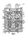
- valve 10 Operation of valve 10 after one movable valve unit has become faulted is shown in Figures 3 and 4.
- the faulted state results when first movable valve unit 18 has failed to return to its deactuated position after turning off of pilot valve 76, for example.
- First movable valve unit 18 is shown at its intermediate position wherein both exhaust piston/poppet 21 and inlet poppet 24 are in an unseated condition. If movable valve unit 18 is in an actuated (i.e., fully downward) position when it first becomes faulted, return spring 35 will attempt to move first movable valve unit 18 to the intermediate position. Spring stop 36 prevents inlet poppet 24 from being moved to its closed position.
- second crossover chamber 54 is coupled to exhaust 16 via one or both of the exhaust valves. With second crossover chamber 54 exhausted, return chamber 37 is exhausted so that no return force can be generated on first movable valve unit 18. Timing chambers 81 and 82 are also exhausted so that double valve 10 is in a locked out condition wherein second movable valve unit 20 cannot be actuated by second pilot valve 83. Since inlet poppet 50 is closed, pressure builds in first crossover chamber 28 even though the other movable valve unit 18 is faulted. Crossover chamber 28 provides pressure to return chamber 63 and to timing chambers 74 and 75.
- pilot valves 76 and 83 when pilot valves 76 and 83 are actuated, faulted valve unit 18 receives full pressure at the top of exhaust piston/poppet 21 and can move into its fully actuated position.
- exhaust piston/poppet 46 is open while inlet poppet is open, significant pressure cannot build in crossover chamber 54. Consequently, pilot valve 83 is not able to provide sufficient pressure to move second movable valve unit 20 from its deactuated position.
- double valve 10 remains in a locked out position at least until both movable valve units are reset by reset pistons 38 and 64.
- inlet pressure is turned off while a movable valve unit is in its fully actuated position, then the valve unit is urged into the intermediate position by the corresponding return spring.
- the return spring cannot move the corresponding movable valve unit beyond the intermediate position due to the corresponding spring stop.
- the movable valve unit is prevented from moving all the way to its deactuated position by friction and/or gravity depending upon the orientation of the double valve. If inlet pressure is restored, pressure from the flow restrictor corresponding to the non-faulted movable valve unit is supplied into a crossover chamber which is open to exhaust through the faulted inlet poppet and at least the exhaust poppet of the non-faulted unit.
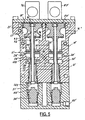
- FIG. 5 shows an alternative embodiment of a double valve 10', which functions in essentially the same manner as the embodiment shown in Figures 1-4. Corresponding parts in Figure 5 are designated using the same reference numbers with an added prime.
- Housing 11' includes a first movable valve unit 18' and a second movable valve unit 20'. Since the units are identical, only movable valve unit 18' will be described in detail.
- a valve stem 22' has an exhaust piston/poppet 21' fixedly mounted at one end by a retaining nut 91.
- a spacer 92 has disc portions 93 and 94 at each axial end.
- Exhaust piston/poppet 21' includes a cavity 95, which is bowl shaped and receives disc portion 93 and an o-ring 96.
- O-ring 96 forms a face seal with exhaust seat 41' in the manner described in co-pending application serial number (attorney docket 2166-206), incorporated herein by reference for all purposes.
- inlet poppet 24' has a cavity 97 for receiving disc shaped portion 94 and an o-ring 98.
- Piston 101 is shaped to provide a flow restrictor 25' between inlet chamber 13' and crossover chamber 28'. Piston 101 has a constant diameter throughout inlet chamber 13' so that it has no surfaces for exerting force in an axial direction on movable valve unit 18'. However, a top surface 102 is exposed to crossover chamber 28' for generating a downward latching force when in the faulted state as described earlier.
- the present invention has the additional advantage that if a machine tool is currently in an operating cycle when the inlet air supply is turned off, then the operating cycle of the machine tool does not resume when inlet air pressure is restored.
Landscapes
- Engineering & Computer Science (AREA)
- Chemical & Material Sciences (AREA)
- Analytical Chemistry (AREA)
- Physics & Mathematics (AREA)
- Fluid Mechanics (AREA)
- Mechanical Engineering (AREA)
- General Engineering & Computer Science (AREA)
- Multiple-Way Valves (AREA)
- Fluid-Pressure Circuits (AREA)
- Safety Devices In Control Systems (AREA)
- Indication Of The Valve Opening Or Closing Status (AREA)
Description
- The present invention relates in general to control valves, and, more specifically, to a double valve for controlling a single flow of pressurized fluid in response to simultaneous activation of a pair of control switches.
- Machine tools of various types operate through a valving system, which interacts with a pneumatically-controlled clutch and/or brake assembly. For safety reasons, the control valves that are used to operate these machine tools require the operator to activate two separate control switches substantially simultaneously to ensure that an operator's hands are away from the moving components of the machine tool when an operating cycle is initiated. Typically, an electronic circuit responsive to the two control switches generates a pilot control signal applied to the pilot valves for switching the main fluid circuit of the valve to control delivery of compressed air (or other fluid) to the machine tool to perform its operating cycle.
- Double valves operating in parallel in one valve body have been developed to ensure that a repeat or overrun of a machine tool operating cycle cannot be caused by malfunction of a single valve unit (e.g., a valve becoming stuck in an actuated position). Thus, if one valve unit fails to deactuate at the proper time, the double valve assumes a configuration that diverts the source of compressed air from the machine tool. A double valve is shown, for example, in commonly assigned
U.S. patent 6,478,049 to Bento et al , which is incorporated herein by reference for all purposes. - In addition to providing protection against the repeat or overrun of the machine tool, it is desirable to monitor the double valve for a faulted valve unit and to prevent a new operating cycle of the machine tool from being initiated. Thus, prior art systems have caused the double valve to assume a lock-out configuration when a single valve unit is in a faulted condition so that the double valve cannot again be actuated until it has been intentionally reset to clear the faulted condition.
- More specifically, a double valve assembly includes two electromagnetically-controlled pilot valves. Typically, the pilot valves are normally closed. The double valve assembly includes two movable valve units, each with a respective exhaust poppet between the outlet port and the exhaust port of the double valve and a respective inlet poppet between the outlet port and the inlet port of the double valve. When the pilot valves are normally closed, then the exhaust poppets are normally open and the inlet poppets are normally closed. Each of the pilot valves is moved to an actuated position in response to an electrical control signal from a respective operator-controlled switch, which typically causes the exhaust poppets to close and the inlet poppets to open. Any time that 1) a valve unit fails to deactuate properly, 2) a valve unit fails to actuate properly, or 3) the pilot valves are actuated or deactuated non-simultaneously, then at least one valve unit becomes locked in a faulted position where its exhaust poppet cannot be closed (thereby preventing the outlet from becoming pressurized).
- During normal running conditions, the inlet to the double valve receives a continuous source of pressurized fluid. However, the source is periodically turned off (e.g., during maintenance or at the end of a work shift). When the pressurized fluid cycles off and on, pressures within different sections of the double valve acting upon various valve components decays and then rebuilds, thereby causing forces on the valve units not typically experienced during normal running conditions. In prior art double valves, the affect upon the movable valve units of cycling the pressure has typically been inconsistent and unpredictable. In many instances, a valve unit that was in a faulted state can end up being reset by the pressure cycling. This is undesirable because the failure of a valve that becomes faulted shortly before cycling the pressure might not be noticed before the pressure is turned off. If the faulted valve is reset by the pressure cycling, then the indication of a malfunction is lost and it may be possible for a valve that should be locked out to attempt to operate normally. On the other hand, it is also possible for a non-malfunctioning valve unit to inadvertently assume the faulted position when no fault has actually occurred, thereby requiring valves to be reset after cycling the pressure off and on which adds inefficiency in a manufacturing operation. Consequently, it would be desirable to provide a dynamic memory of the valve state during the cycling of inlet pressure so that each valve unit resumes the same state as it had when the pressure was removed.
-
EP 1255047 discloses a control valve system comprising first and second pluralities of valves, each plurality of valves being moveable between an actuated position, a deactuated position and an intermediate position. A plurality of reset members are selectively engageable with the first plurality of valves. - The present invention seeks to provide a double valve with memory such that when the valve is in its normal deactuated state and the inlet air supply is cycled (e.g., turned from on to off or from off to on), then the valve remains in the deactuated (i.e., ready to run) state. When the valve is in a faulted state (e.g., intermediate position) and the inlet air supply is cycled, then the valve remains in the faulted state. The memory is achieved by a balanced condition of the movable valve elements when in the normal deactuated position and an unbalanced or latched condition when in the intermediate or faulted position.
- According to the present invention there is provided a control valve system as disclosed in
claim 1. - In one aspect of the invention, the control valve system comprises a housing defining an inlet; an outlet and an exhaust, wherein the inlet is adapted to receive pressurized fluid. A first movable valve unit includes a first exhaust poppet and a first inlet poppet, wherein the first exhaust poppet is movable between an open position for coupling the outlet to the exhaust and a closed position for isolating the outlet from the exhaust, and wherein the first inlet poppet is movable between an open position for coupling the outlet to the inlet and a closed position for isolating the outlet from the inlet. The first movable valve unit is movable to an actuated position, a deactuated position, and an intermediate position, wherein the actuated position comprises the first inlet poppet being in its open position and the first exhaust poppet being in its closed position, wherein the deactuated position comprises the first inlet poppet being in its closed position and the first exhaust poppet being in its open position, and wherein the intermediate position comprises the first inlet poppet and the first exhaust poppet both being at least partially open.
- A second movable valve unit includes a second exhaust poppet and a second inlet poppet, wherein the second exhaust poppet is movable between an open position for coupling the outlet to the exhaust and a closed position for isolating the outlet from the exhaust, and wherein the second inlet poppet is movable between an open position for coupling the outlet to the inlet and a closed position for isolating the outlet from the inlet. The second movable valve unit is movable to an actuated position, a deactuated position, and an intermediate position, wherein the actuated position comprises the second inlet poppet being in its open position and the second exhaust poppet being in its closed position, wherein the deactuated position comprises the second inlet poppet being in its closed position and the second exhaust poppet being in its open position, and wherein the intermediate position comprises the second inlet poppet and the second exhaust poppet both being at least partially open.
- First and second crossover chambers communicate with the second and first inlet poppets, respectively. First and second flow restrictors couple the inlet to the first and second crossover chambers, respectively. First and second pilot valves are disposed at one end of the first and second movable valve units, respectively, for selectably urging the first and second movable valve units to the respective actuated positions.
- When one of the first and second units is in the deactuated position and the pressurized fluid is removed from the inlet then substantially no net forces act on the one unit and it remains in the deactuated position. When the pressurized fluid is restored to the inlet then the one unit is urged into the deactuated position in response to pressure resulting from fluid flow into a corresponding crossover chamber via a respective flow restrictor.
- According to another aspect of the present invention, there is provided a method of providing memory of a normal valve state and a faulted valve state in a control valve system as disclosed in
claim 10. -
- Figure 1 is a cross-sectional view of a double valve according to a first embodiment of the present invention in its normal deactuated position.
- Figure 2 is a cross-sectional view of double valve of Figure 1 in its normal actuated position.
- Figure 3 is a cross-sectional view of double valve of Figure 1 in a faulted state.
- Figure 4 is a cross-sectional view of double valve of Figure 1 in a faulted state with the pilot valves turned on and attempting to actuate the double valve.
- Figure 5 is a cross-sectional view of double valve according to a second embodiment of the present invention in its normal deactuated position.
- Figure 6 is a state diagram showing the operation of a double valve according to the present invention when inlet pressure is cycled off and on.
- Referring now to Figure 1, a control valve system in the form of a
double valve 10 includes a housing 11 having aninlet port 12 leading to aninlet chamber 13, anoutlet port 14 leading to anoutlet chamber 15, and anexhaust port 16 leading to anexhaust chamber 17. Housing 11 may include separate blocks 11a - 11d which may be clamped or bolted together. - Chambers 13, 15, and 17 are joined by various passages to create elongated bores for receiving a first
movable valve unit 18 and a secondmovable valve unit 20. Firstmovable valve unit 18 includes an exhaust piston/piston/poppet 21 slidably received at one end of a stem 22 via a piston 23. Firstmovable valve unit 18 also includes aninlet poppet 24 and aflow restrictor 25. A disk-shaped shoulder 26 extends from aspacer 34 that is fixed to stem 22. Shoulder 26 is slidably received in a passage 27 formingflow restrictor 25 so that pressurized fluid frominlet chamber 13 flows at a reduced rate into afirst crossover chamber 28 when shoulder 26 is present in passage 27. - The lower end of stem 22 receives
pistons retainer nut 33 threaded to one end of stem 22. Pistons 30 and 31 are slidably received in abushing 32 which is rigidly retained within housing 11. - A
spring stop 36 is slidably received onspacer 34 and is urged in an upward direction by areturn spring 35. Beneathmovable valve unit 18, areturn chamber 37 is formed which receives part of areset piston 38 and apiston return spring 40. - First
movable valve unit 18 is shown in Figure 1 in its deactuated position whereinoutlet port 14 is open toexhaust port 16 and closed toinlet port 12. Thus, exhaust piston/poppet 21 is in its upward, deactuated position wherein anexhaust seal 42 is spaced away from an exhaust seat 41. At the same time, aninlet seal 44 ofinlet poppet 24 is disposed against aninlet seat 43. - Second
movable valve unit 20 includes an exhaust piston/poppet 46 slidably received at one end of astem 47 via apiston 48. Secondmovable valve unit 20 also includes aninlet poppet 50 and aflow restrictor 51. A disk-shapedshoulder 52 extends from aspacer 60 that is fixed to stem 47.Shoulder 52 is slidably received in apassage 53 formingflow restrictor 51 so that pressurized fluid frominlet chamber 13 flows at a reduced rate into asecond crossover chamber 54 whenshoulder 52 is present inpassage 53. - The lower end of
stem 47 receivespistons retainer nut 58 threaded to one end ofstem 47.Pistons bushing 57 which is rigidly retained within housing 11. - A
spring stop 62 is slidably received onspacer 60 and is urged in an upward direction by areturn spring 61. Beneathmovable valve unit 20, areturn chamber 63 is formed which receives part of areset piston 64 and apiston return spring 65. - Second
movable valve unit 20 is shown in Figure 1 in its deactuated position whereinoutlet port 14 is open to exhaustport 16 and closed toinlet port 12. Thus, exhaust piston/poppet 46 is in its upward, deactuated position wherein anexhaust seal 67 is spaced away from anexhaust seat 66. At the same time, aninlet seal 70 ofinlet poppet 50 is disposed against aninlet seat 68. - A
fluid passage 72 provides fluid communication betweenfirst crossover chamber 28 and returnchamber 63 of secondmovable valve unit 20. Afluid passage 73 provides fluid communication fromfirst crossover chamber 28 to timingchambers first pilot valve 76. Apassage 77 is coupled between the output offirst pilot valve 76 and the upper surface of exhaust piston/poppet 21. - A
fluid passage 78 provides fluid communication betweensecond crossover chamber 54 and returnchamber 37 of firstmovable valve unit 18. Afluid passage 80 provides fluid communication fromsecond crossover chamber 54 to timingchambers second pilot valve 83. Apassage 84 is coupled between the output ofsecond pilot valve 83 and the upper surface of exhaust piston/poppet 46. - A
reset port 85 communicates with areset passage 86 for providing reset pressure to resetpistons movable valve units units valve units pistons - When inlet pressure is first applied to
inlet port 12, the movable valve units remain at their deactuated positions as follows. The pressure ininlet chamber 13 immediately reflects the increased pressure atinlet port 12. The surfaces of firstmovable valve unit 18 that are open toinlet chamber 13 include afirst side 87 of shoulder 26 and an upper surface 89 ofpiston 30. These surfaces are provided with equal areas such that inlet pressure against the surfaces creates an upward force againstsurface 87 which is substantially exactly counterbalanced by a downward force against surface 89. Similarly, a surface 88 ofshoulder 52 has an area substantially equal to a surface 90 ofpiston 55. Thus, a net force of substantially zero acts upon each of the movable valve units in response to the build up of pressure ininlet chamber 13. - Due to the imperfect seals of
flow restrictors crossover chambers inlet poppets respective seats chambers pilot valves inlet chamber 13. - Figure 2 shows
double valve 10 in its normal actuated state. Since timingchambers pilot valves poppets valve seats 41 and 66, respectively. Exhaust piston/poppets inlet poppets Shoulders 26 and 52 ofspacers - When the pilot valves are deactuated, pressurized fluid pressing against the top of exhaust piston/
poppets outlet chamber 15 and returnchambers movable valve units inlet chamber 13. As a result, first and secondmovable valve units pilot valves chambers - Operation of
valve 10 after one movable valve unit has become faulted is shown in Figures 3 and 4. As shown in Figure 3, the faulted state results when firstmovable valve unit 18 has failed to return to its deactuated position after turning off ofpilot valve 76, for example. Firstmovable valve unit 18 is shown at its intermediate position wherein both exhaust piston/poppet 21 andinlet poppet 24 are in an unseated condition. Ifmovable valve unit 18 is in an actuated (i.e., fully downward) position when it first becomes faulted,return spring 35 will attempt to move firstmovable valve unit 18 to the intermediate position.Spring stop 36 preventsinlet poppet 24 from being moved to its closed position. Withinlet poppet 24 open,second crossover chamber 54 is coupled to exhaust 16 via one or both of the exhaust valves. Withsecond crossover chamber 54 exhausted, returnchamber 37 is exhausted so that no return force can be generated on firstmovable valve unit 18. Timingchambers double valve 10 is in a locked out condition wherein secondmovable valve unit 20 cannot be actuated bysecond pilot valve 83. Sinceinlet poppet 50 is closed, pressure builds infirst crossover chamber 28 even though the othermovable valve unit 18 is faulted.Crossover chamber 28 provides pressure to returnchamber 63 and to timingchambers pilot valves valve unit 18 receives full pressure at the top of exhaust piston/poppet 21 and can move into its fully actuated position. However, since exhaust piston/poppet 46 is open while inlet poppet is open, significant pressure cannot build incrossover chamber 54. Consequently,pilot valve 83 is not able to provide sufficient pressure to move secondmovable valve unit 20 from its deactuated position. Thus,double valve 10 remains in a locked out position at least until both movable valve units are reset byreset pistons - In the event that inlet pressure is turned off while a movable valve unit is in its fully actuated position, then the valve unit is urged into the intermediate position by the corresponding return spring. The return spring cannot move the corresponding movable valve unit beyond the intermediate position due to the corresponding spring stop. The movable valve unit is prevented from moving all the way to its deactuated position by friction and/or gravity depending upon the orientation of the double valve. If inlet pressure is restored, pressure from the flow restrictor corresponding to the non-faulted movable valve unit is supplied into a crossover chamber which is open to exhaust through the faulted inlet poppet and at least the exhaust poppet of the non-faulted unit. Since full pressure builds up in the other crossover chamber (i.e., the crossover chamber fed by the flow restrictor of the faulted valve unit), a downward pressure against the flow restrictor from within the crossover chamber latches the faulted movable valve unit in the intermediate position against the return spring.
- Figure 5 shows an alternative embodiment of a double valve 10', which functions in essentially the same manner as the embodiment shown in Figures 1-4. Corresponding parts in Figure 5 are designated using the same reference numbers with an added prime. Housing 11' includes a first movable valve unit 18' and a second movable valve unit 20'. Since the units are identical, only movable valve unit 18' will be described in detail.
- A valve stem 22' has an exhaust piston/poppet 21' fixedly mounted at one end by a retaining nut 91. A spacer 92 has
disc portions cavity 95, which is bowl shaped and receivesdisc portion 93 and an o-ring 96. O-ring 96 forms a face seal with exhaust seat 41' in the manner described in co-pending application serial number (attorney docket 2166-206), incorporated herein by reference for all purposes. Likewise, inlet poppet 24' has acavity 97 for receiving disc shapedportion 94 and an o-ring 98. - Also mounted to stem 22' are a
spacer 100 and apiston 101. Aboss 103 at the bottom end of stem 22' clamps the poppets, spacers, and piston in a fixed relationship on stem 22'.Piston 101 is shaped to provide a flow restrictor 25' between inlet chamber 13' and crossover chamber 28'.Piston 101 has a constant diameter throughout inlet chamber 13' so that it has no surfaces for exerting force in an axial direction on movable valve unit 18'. However, atop surface 102 is exposed to crossover chamber 28' for generating a downward latching force when in the faulted state as described earlier. - The transitions between operating states of the double valve of the present invention is shown in greater detail in Figure 6. Beginning in a normal
deactuated state 110 and if inlet pressure is cycled from on to off, then when the pressure decays a transition is made to a state 111 wherein the movable valve units are balanced in the deatuated position. Due to the balanced condition, the movable valve units are not moved regardless of any residual pressure in the inlet chamber. In other words, no net forces act on a valve unit and it remains in the deactuated position by virtue of friction between the valve units and the housing. When pressure is restored, the rising inlet pressure in the inlet chamber generates no net force against a valve unit. Fluid passes through the flow restrictors and builds pressure in the crossover chambers, resulting in a pressure that positively retains the valve units in the deactuated positions and a return is made to normaldeactuated state 110. - From
state 110, when both pilot valves are simultaneously actuated then a transition is made to normal actuated state 112. When the pilots are deactuated (e.g., be terminating the push button switch signals near the end of a machine operating cycle), then the valve units return to the deactuated position and the valve returns to normaldeactuated state 110. If a fault occurs, however, a transition is made to faultedstate 113 wherein the faulted valve units are prevented from deactuating. - If pressure at the inlet is removed, then a transition is made to
state 114 wherein the faulted units are latched in the intermediate position by the action of the return spring and spring stops. When pressure is restored, the faulted valve unit is prevented from entering the deactuated position by returning tostate 113. - If inlet pressure is cycled from on to off while in a normal actuated state 112, then as the pressure decays the valve units will both latch in the intermediate position and the valve will enter
state 114. When pressure is restored, the valve continues to be locked out in a faulted condition instate 113 even though the valve was in a normal condition when pressure was turned off. Thus, the present invention has the additional advantage that if a machine tool is currently in an operating cycle when the inlet air supply is turned off, then the operating cycle of the machine tool does not resume when inlet air pressure is restored.
Claims (12)
- A control valve system comprising:a housing (11) defining an inlet port (12) leading to an inlet chamber (13), an outlet (14) and an exhaust (16), said inlet port (12) being adapted to receive pressurized fluid;a first movable valve unit (18) including a first exhaust poppet (21) and a first inlet poppet (24), wherein said first exhaust poppet (21) is movable between an open position for coupling said outlet (14) to said exhaust (16) and a closed position for isolating said outlet (14) from said exhaust (16), wherein said first inlet poppet (24) is movable between an open position for coupling said outlet (14) to said inlet chamber (13) and a closed position for isolating said outlet (14) from said inlet chamber (13), wherein said first movable valve unit (18) is movable to an actuated position, a deactuated position, and an intermediate position, wherein said actuated position comprises said first inlet poppet (24) being in its open position and said first exhaust poppet (21) being in its closed position, wherein said deactuated position comprises said first inlet poppet (24) being in its closed position and said first exhaust poppet (21) being in its open position, and wherein said intermediate position comprises said first inlet poppet (24) and said first exhaust poppet (21) both being at least partially open;a second movable valve unit (20) including a second exhaust poppet (46) and a second inlet poppet (50), wherein said second exhaust poppet (46) is movable between an open position for coupling said outlet (14) to said exhaust (16) and a closed position for isolating said outlet (14) from said exhaust (16), wherein said second inlet poppet (50) is movable between an open position for coupling said outlet (14) to said inlet chamber (13) and a closed position for isolating said outlet (14) from said inlet chamber (13), wherein said second movable valve unit (20) is movable to an actuated position, a deactuated position, and an intermediate position, wherein said actuated position comprises said second inlet poppet (50) being in its open position and said second exhaust poppet (46) being in its closed position, wherein said deactuated position comprises said second inlet poppet (50) being in its closed position and said second exhaust poppet (46) being in its open position, and wherein said intermediate position comprises said second inlet poppet (50) and said second exhaust poppet (46) both being at least partially open;first and second crossover chambers (28, 54) communicating with said second (50) and first (24) inlet poppets, respectively;first and second flow restrictors (25, 51) coupling said inlet chamber (13) to said first (28) and second (54) crossover chambers, respectively; andfirst and second pilot valves (76, 83) disposed at one end of said first (18) and second (20) movable valve units, respectively, for selectably urging said first (18) and second (20) movable valve units to said respective actuated positions,characterised in that;
when one of said first (18) and second (20) units is in said deactuated position and said pressurized fluid is removed from said inlet port (12) then substantially no net forces act on said one unit (18, 20) and it remains in said deactuated position, and when said pressurized fluid is restored to said inlet port (12) then said one unit (18, 20) is urged into said deactuated position in response to pressure resulting from fluid flow into a corresponding crossover chamber (28, 54) via a respective flow restrictor (25, 51). - The control valve system of claim 1 wherein said first (18) and second (20) movable valve units are shaped such that said pressurized fluid in said inlet chamber (13) produces forces acting on said first (18) and second (20) valve units with substantially no components in an axial direction of said first (18) and second (20) movable valve units.
- The control valve system of claim 2 wherein portions of said first (18) and second (20) valve units exposed to said pressurized fluid in said inlet chamber (13) are cylindrically shaped with a substantially constant diameter.
- The control valve system of claim 2 wherein said first (25) and second (51) flow restrictors comprise first (26) and second (52) shoulders on said first (18) and second (20) movable valve units, respectively, each shoulder (26, 52) having a respective inlet side (87, 88) with a respective surface area exposed to said inlet chamber (13), and wherein said first (18) and second (20) movable valve units include first (89) and second (90) piston surfaces opposing said first (26) and second (52) shoulders, respectively, and exposed to said inlet chamber (13), said first (89) and second (90) piston surfaces providing respective surface areas equal to said surface areas of said inlet sides (87, 88) of said respective shoulders (26, 52).
- The control valve system of claim 1 further comprising a spring stop (36, 62) that is urged in an upward direction by a return spring (35, 61), wherein when one of said first (18) and second (20) units is in said actuated position or said intermediate position and said pressurized fluid is removed from said inlet port (12) then said one unit (18, 20) is urged into the intermediate position by the corresponding return spring (35, 61), said one unit being prevented from moving into said deactuated position due to the corresponding spring stop (36, 62), and said one unit (18, 20) being further prevented from moving into said deactuated position at least partially by friction and at least partially by gravity.
- The control valve system of claim 1 wherein when one of said first (18) and second (20) units is in said actuated position or said intermediate position and said pressurized fluid is removed from said inlet port (12) then said one unit (18, 20) is prevented from moving into said deactuated position, and wherein when said pressurized fluid is restored to said inlet port (12) then said one unit (18, 20) is urged away from said deactuated position in response to pressure built up in a respective crossover chamber (28, 54) exerting a downward pressure against a corresponding flow restrictor (25, 51).
- The control valve system of claim 1 further comprising:first and second return springs (35, 61) for urging said first and second movable valve units (18, 20) from said actuated position into said intermediate position.
- The control valve system of claim 7 wherein when one of said first and second units (18, 20) is in said actuated position or said intermediate position and said pressurized fluid is removed from said inlet port (12) then said one unit (18, 20) is urged into said intermediate position by a respective return spring (35, 61), and wherein when said pressurized fluid is restored to said inlet port (12) then said one unit (18, 20) is retained in said intermediate position against said respective return spring (35, 61) in response to pressure built up in a respective crossover chamber (28, 54).
- The control valve system of claim 1 further comprising:first and second return chambers (37, 63) disposed at the other end of said first and second movable valve units (18, 20), respectively, wherein said first and second return chambers (37, 63) are coupled to said second and first crossover chambers (54, 28), respectively.
- A method of providing memory of a normal valve state and a faulted valve state in a control valve system, wherein said control valve system includes a housing (11) defining an inlet port (12) leading to an inlet chamber (13), an outlet (14) and an exhaust (16), said inlet port (12) being adapted to receive pressurized fluid, wherein said control valve system includes a first movable valve unit (18) including a first exhaust poppet (21) and a first inlet poppet (24), wherein said first movable valve unit (18) is movable to an actuated position, a deactuated position, and an intermediate position, wherein said control valve system includes a second movable valve unit (20) including a second exhaust poppet (46) and a second inlet poppet (50), wherein said second movable valve unit (20) is movable to an actuated position, a deactuated position, and an intermediate position, wherein said control valve system includes first and second crossover chambers (28, 54) communicating with said second (50) and first (24) inlet poppets, respectively, wherein said control valve system includes first and second flow restrictors (25, 51) coupling said inlet chamber (13) to said first (28) and second (54) crossover chambers, respectively, wherein said control valve system includes first and second pilot valves (76, 83) disposed at one end of said first(18) and second (20) movable valve units, respectively, that are activated to selectably urge said first (18) and second (20) movable valve units to said respective actuated positions, wherein a normal valve state is comprised of a movable valve unit (18, 20) being in said deactuated position when a respective pilot valve (76, 83) is not activated, and wherein said faulted valve state is comprised of a movable valve unit (18, 20) being in said actuated position or said intermediate position when a respective pilot valve (76, 83) is not activated, said method characterised by:when a movable valve unit (18, 20) is in said normal valve state, then balancing said movable valve unit (18, 20) at said deactuated position when said inlet pressure is cycled off and on; andwhen a movable valve unit (18, 20) is in said faulted valve state, then latching said movable valve unit (18, 20) at said intermediate position when said inlet pressure is cycled off and on.
- The method of claim 10 wherein said movable valve units (18, 20) are shaped such that pressurized fluid in said inlet chamber (13) generates substantially no net forces on said movable valve units (18, 20) in their axial direction.
- The method of claim 10 wherein said latching step comprises building pressure in a respective crossover chamber (28, 54) of one movable valve unit (18, 20) in a faulted valve state, said respective crossover chamber (28, 54) being sealed by the other movable valve unit (18, 20) being in a normal valve state.
Applications Claiming Priority (2)
| Application Number | Priority Date | Filing Date | Title |
|---|---|---|---|
| US660993 | 2003-09-12 | ||
| US10/660,993 US6840259B1 (en) | 2003-09-12 | 2003-09-12 | Dynamically-monitored double valve with retained memory of valve states |
Publications (3)
| Publication Number | Publication Date |
|---|---|
| EP1515052A2 EP1515052A2 (en) | 2005-03-16 |
| EP1515052A3 EP1515052A3 (en) | 2005-07-13 |
| EP1515052B1 true EP1515052B1 (en) | 2007-09-19 |
Family
ID=33553004
Family Applications (1)
| Application Number | Title | Priority Date | Filing Date |
|---|---|---|---|
| EP20040255062 Expired - Lifetime EP1515052B1 (en) | 2003-09-12 | 2004-08-23 | Dynamically-monitored double valve with retained memory of valve states |
Country Status (7)
| Country | Link |
|---|---|
| US (1) | US6840259B1 (en) |
| EP (1) | EP1515052B1 (en) |
| JP (1) | JP4615270B2 (en) |
| CN (1) | CN100439721C (en) |
| BR (1) | BRPI0403775B1 (en) |
| DE (1) | DE602004009008T2 (en) |
| ES (1) | ES2290636T3 (en) |
Families Citing this family (5)
| Publication number | Priority date | Publication date | Assignee | Title |
|---|---|---|---|---|
| US6840258B1 (en) * | 2003-09-12 | 2005-01-11 | Ross Operating Valve Company | Dynamically-monitored double valve with anti-tiedown feature |
| US7438086B2 (en) * | 2006-02-02 | 2008-10-21 | Ross Controls | Dynamic fluid power monitoring system for separate actuators |
| US8028717B2 (en) * | 2007-10-04 | 2011-10-04 | Ross Operating Valve Company | High throughput double valve with reduced outlet pressure during a faulted state |
| US8794123B2 (en) | 2010-03-12 | 2014-08-05 | Ross Operating Valve Company | Double valve constructed from unitary single valves |
| US9945494B2 (en) * | 2013-06-04 | 2018-04-17 | Spx Flow, Inc. | Pneumatic directional valve and method of operation |
Family Cites Families (10)
| Publication number | Priority date | Publication date | Assignee | Title |
|---|---|---|---|---|
| US4542767A (en) | 1983-04-05 | 1985-09-24 | Ross Operating Valve Company | Monitor for double safety valves |
| SE505573C2 (en) | 1995-12-19 | 1997-09-15 | Ross Operating Valve Co | Control device with self-control of the control device components during each control operation |
| SE9600697L (en) | 1996-02-23 | 1997-03-24 | Ross Operating Valve Co | Feedback lock for one self-controlling controller in each work cycle |
| JPH1056003A (en) * | 1996-08-09 | 1998-02-24 | Sony Corp | Dry etching method |
| US5850852A (en) * | 1996-12-16 | 1998-12-22 | Ross Operating Valve Company | Crossflow with crossmirror and lock out capability valve |
| US6155293A (en) * | 1996-12-16 | 2000-12-05 | Ross Operating Valve Company | Double valve with anti-tiedown capability |
| US5927324A (en) | 1996-12-16 | 1999-07-27 | Ross Operating Valve Company | Cross flow with crossmirror and lock out capability valve |
| US6478049B2 (en) * | 1996-12-16 | 2002-11-12 | Ross Operating Valve Company | Double valve with anti-tiedown capability |
| US6604547B1 (en) * | 2002-02-19 | 2003-08-12 | Ross Operating Valve Company | Double valve with cross exhaust |
| US6840258B1 (en) * | 2003-09-12 | 2005-01-11 | Ross Operating Valve Company | Dynamically-monitored double valve with anti-tiedown feature |
-
2003
- 2003-09-12 US US10/660,993 patent/US6840259B1/en not_active Expired - Lifetime
-
2004
- 2004-08-23 EP EP20040255062 patent/EP1515052B1/en not_active Expired - Lifetime
- 2004-08-23 ES ES04255062T patent/ES2290636T3/en not_active Expired - Lifetime
- 2004-08-23 DE DE200460009008 patent/DE602004009008T2/en not_active Expired - Lifetime
- 2004-08-31 JP JP2004251950A patent/JP4615270B2/en not_active Expired - Lifetime
- 2004-09-08 BR BRPI0403775-8A patent/BRPI0403775B1/en active IP Right Grant
- 2004-09-10 CN CNB200410077141XA patent/CN100439721C/en not_active Expired - Lifetime
Non-Patent Citations (1)
| Title |
|---|
| None * |
Also Published As
| Publication number | Publication date |
|---|---|
| CN1594899A (en) | 2005-03-16 |
| EP1515052A2 (en) | 2005-03-16 |
| US6840259B1 (en) | 2005-01-11 |
| DE602004009008D1 (en) | 2007-10-31 |
| DE602004009008T2 (en) | 2008-06-19 |
| EP1515052A3 (en) | 2005-07-13 |
| CN100439721C (en) | 2008-12-03 |
| JP2005090741A (en) | 2005-04-07 |
| ES2290636T3 (en) | 2008-02-16 |
| JP4615270B2 (en) | 2011-01-19 |
| BRPI0403775B1 (en) | 2017-07-18 |
| BRPI0403775A (en) | 2005-06-07 |
Similar Documents
| Publication | Publication Date | Title |
|---|---|---|
| EP2545286B1 (en) | Double valve constructed from unitary single valves | |
| EP1059460B1 (en) | Double valve with anti-tiedown capability | |
| CA2220919C (en) | Crossflow with crossmirror and lock out capability valve | |
| US5927324A (en) | Cross flow with crossmirror and lock out capability valve | |
| CN101868633B (en) | High throughput double valve with reduced outlet pressure during a faulted state | |
| EP1515052B1 (en) | Dynamically-monitored double valve with retained memory of valve states | |
| EP1255047B1 (en) | Double valve with anti-tiedown capability | |
| EP1512873B1 (en) | Double valve constructed from unitary single valves | |
| EP1515053B1 (en) | Double valve with anti-tiedown feature | |
| US6604547B1 (en) | Double valve with cross exhaust | |
| EP1255048B1 (en) | Control valve system | |
| EP1069323B1 (en) | Cross flow with crossmirror and lock out capability valve | |
| CA2330493C (en) | Crossflow with crossmirror and lock out capability valve |
Legal Events
| Date | Code | Title | Description |
|---|---|---|---|
| PUAI | Public reference made under article 153(3) epc to a published international application that has entered the european phase |
Free format text: ORIGINAL CODE: 0009012 |
|
| AK | Designated contracting states |
Kind code of ref document: A2 Designated state(s): AT BE BG CH CY CZ DE DK EE ES FI FR GB GR HU IE IT LI LU MC NL PL PT RO SE SI SK TR |
|
| AX | Request for extension of the european patent |
Extension state: AL HR LT LV MK |
|
| PUAL | Search report despatched |
Free format text: ORIGINAL CODE: 0009013 |
|
| AK | Designated contracting states |
Kind code of ref document: A3 Designated state(s): AT BE BG CH CY CZ DE DK EE ES FI FR GB GR HU IE IT LI LU MC NL PL PT RO SE SI SK TR |
|
| AX | Request for extension of the european patent |
Extension state: AL HR LT LV MK |
|
| 17P | Request for examination filed |
Effective date: 20060109 |
|
| AKX | Designation fees paid |
Designated state(s): DE ES FR GB IT |
|
| RAP1 | Party data changed (applicant data changed or rights of an application transferred) |
Owner name: ROSS OPERATING VALVE COMPANY |
|
| GRAP | Despatch of communication of intention to grant a patent |
Free format text: ORIGINAL CODE: EPIDOSNIGR1 |
|
| GRAS | Grant fee paid |
Free format text: ORIGINAL CODE: EPIDOSNIGR3 |
|
| GRAA | (expected) grant |
Free format text: ORIGINAL CODE: 0009210 |
|
| AK | Designated contracting states |
Kind code of ref document: B1 Designated state(s): DE ES FR GB IT |
|
| REG | Reference to a national code |
Ref country code: GB Ref legal event code: FG4D |
|
| REF | Corresponds to: |
Ref document number: 602004009008 Country of ref document: DE Date of ref document: 20071031 Kind code of ref document: P |
|
| REG | Reference to a national code |
Ref country code: ES Ref legal event code: FG2A Ref document number: 2290636 Country of ref document: ES Kind code of ref document: T3 |
|
| ET | Fr: translation filed | ||
| PLBE | No opposition filed within time limit |
Free format text: ORIGINAL CODE: 0009261 |
|
| STAA | Information on the status of an ep patent application or granted ep patent |
Free format text: STATUS: NO OPPOSITION FILED WITHIN TIME LIMIT |
|
| 26N | No opposition filed |
Effective date: 20080620 |
|
| PGFP | Annual fee paid to national office [announced via postgrant information from national office to epo] |
Ref country code: ES Payment date: 20080808 Year of fee payment: 5 |
|
| PGFP | Annual fee paid to national office [announced via postgrant information from national office to epo] |
Ref country code: FR Payment date: 20080807 Year of fee payment: 5 |
|
| PGFP | Annual fee paid to national office [announced via postgrant information from national office to epo] |
Ref country code: GB Payment date: 20090708 Year of fee payment: 6 |
|
| REG | Reference to a national code |
Ref country code: FR Ref legal event code: ST Effective date: 20100430 |
|
| PG25 | Lapsed in a contracting state [announced via postgrant information from national office to epo] |
Ref country code: FR Free format text: LAPSE BECAUSE OF NON-PAYMENT OF DUE FEES Effective date: 20090831 |
|
| REG | Reference to a national code |
Ref country code: ES Ref legal event code: FD2A Effective date: 20090824 |
|
| GBPC | Gb: european patent ceased through non-payment of renewal fee |
Effective date: 20100823 |
|
| PG25 | Lapsed in a contracting state [announced via postgrant information from national office to epo] |
Ref country code: GB Free format text: LAPSE BECAUSE OF NON-PAYMENT OF DUE FEES Effective date: 20100823 |
|
| PG25 | Lapsed in a contracting state [announced via postgrant information from national office to epo] |
Ref country code: ES Free format text: LAPSE BECAUSE OF NON-PAYMENT OF DUE FEES Effective date: 20090824 |
|
| REG | Reference to a national code |
Ref country code: DE Ref legal event code: R082 Ref document number: 602004009008 Country of ref document: DE Representative=s name: HASELTINE LAKE LLP, DE |
|
| REG | Reference to a national code |
Ref country code: DE Ref legal event code: R082 Ref document number: 602004009008 Country of ref document: DE Representative=s name: HL KEMPNER PATENTANWAELTE, SOLICITORS (ENGLAND, DE Ref country code: DE Ref legal event code: R082 Ref document number: 602004009008 Country of ref document: DE Representative=s name: HL KEMPNER PATENTANWALT, RECHTSANWALT, SOLICIT, DE |
|
| PGFP | Annual fee paid to national office [announced via postgrant information from national office to epo] |
Ref country code: IT Payment date: 20230711 Year of fee payment: 20 |
|
| PGFP | Annual fee paid to national office [announced via postgrant information from national office to epo] |
Ref country code: DE Payment date: 20230627 Year of fee payment: 20 |
|
| REG | Reference to a national code |
Ref country code: DE Ref legal event code: R071 Ref document number: 602004009008 Country of ref document: DE |