BACKGROUND OF THE INVENTION
-
The present invention relates to a swash plate type
variable displacement compressor, which is capable of changing
its displacement.
-
For example, in a refrigerant circuit of a vehicle air
conditioner, a swash plate type variable displacement
compressor is typically used as a refrigerant compressor. The
swash plate type variable displacement compressor includes a
drive shaft coupled to an output shaft of an engine, a swash
plate that is tiltably supported by and rotates integrally
with the drive shaft, and pistons each engaged with the swash
plate with shoes.
-
Since the swash plate type variable displacement
compressor has the configuration shown above, when swash plate
rotates as the drive shaft rotates, the swash plate slides
across the shoes and wobbles back and forth apparently in a
direction along the axis of the drive shaft. Wobbling of the
swash plate causes the pistons to reciprocate to compress gas.
Also, by changing the inclination angle of the swash plate
relative to the drive shaft, the stroke of the pistons is
varied. Accordingly, the displacement of the swash plate type
variable displacement compressor is changed.
-
A clutchless type compressor is known as one of the swash
plate type variable displacement compressors other than a
clutch type compressor, which is another swash plate type
variable displacement compressor equipped with a clutch in a
power transmission mechanism between its drive shaft and an
engine. The clutchless type compressor has no clutch in the
power transmission mechanism and permits power of the engine
to be constantly transmitted. That is, the drive shaft of the
swash plate type variable displacement compressor having no
clutch is constantly rotated by the drive shaft of the engine
when the engine is running. Therefore, when cooling is not
needed, the vehicle air conditioner causes the compressor to
perform an "OFF operation", in which the displacement of the
swash plate type variable displacement compressor is
minimized. Accordingly, the load on the engine (load for
driving the swash plate type variable displacement compressor)
is reduced, thereby improving the fuel economy of the engine.
-
The swash plate type variable displacement compressor
having no clutch, that is the clutchless type compressor, has
shoes that slide on a swash plate. Therefore, mechanical loss
due to frictional resistance at the contacting portions of the
swash plate and the shoes is great, thereby increasing the
load on the engine. Particularly, in the swash plate type
variable displacement compressor having no clutch, mechanical
loss at the contacting portions of the swash plate and the
shoes have been desired to be reduced for the same of
decreasing the load on the engine during the OFF operation.
-
In response to such demand, improved structures of swash
plate type variable displacement compressors have been
proposed' (for example, see Fig. 1 of Japanese Laid-Open Patent
Publication No 10-196525). In a typical improvement, a swash
plate guiding member is coupled to a drive shaft to rotate
integrally with and incline relative to the drive shaft. A
swash plate is supported by the guiding member with bearings.
When the guiding member rotates as the drive shaft rotates,
the guiding member slips relative to the swash plate.
Accordingly, the rotation speed of the swash plate is lower
than that of the guiding member. Accordingly, the relative
rotation speed of the swash plate and the shoes is lower than
the relative rotation speed of the shoes and the guiding
member. This reduces the mechanical loss at the contacting
portions of the swash plate and the shoes. As a result, the
load of the swash plate type variable displacement compressor
acting on the engine is reduced.
-
However, since the rotation speed of the swash plate is
lower than that of the guiding member in the above described
improved swash plate type variable displacement compressor,
the swash plate only receives a slight centrifugal force.
Centrifugal force of the swash plate acts to cancel the
inertial force of the piston, which is generated by
reciprocation of the piston. Specifically, while the
centrifugal force of the swash plate acts to decrease the
inclination angle of the swash plate, the inertial force of
the pistons act to increase the inclination angle of the swash
plate.
-
Therefore, if the swash plate only receives said slight
centrifugal force, the inclination angle of the swash plate
cannot be smoothly.decreased against the inertial force of the
pistons. This adversely affects the displacement control of
the swash plate type variable displacement compressor.
Particularly, when the swash plate type variable displacement
compressor is operating at a high speed (high-speed rotation
of the drive shaft), that is, when the inertial force of the
piston is great, the problem is serious.
-
As described above, the prior art has a dilemma. That
is, if the displacement control of a swash plate type variable
displacement compressor is prioritized, the mechanical loss
between the swash plate and the shoes is increased.
Conversely, if reduction of mechanical loss generated between
the swash plate and the shoes is prioritized, the displacement
control of the swash plate type variable displacement
compressor is degraded.
SUMMARY OF THE INVENTION
-
Accordingly, it is an objective of the present invention
to provide a swash plate type variable displacement compressor
that is capable of switching between a state where improving
the displacement controllability is prioritized and a state
where reduction of mechanical loss between the swash plate and
the shoes is prioritized.
-
To achieve the above-mentioned objective, the present
invention provides a swash plate type variable displacement
compressor. The compressor includes a drive shaft, a swash
plate guiding member that is coupled to the drive shaft. The
guiding member rotates integrally with and inclines relative
to the drive shaft. The compressor further includes a swash
plate supported by the guiding member, a shoe, and a piston
engaged with the swash plate via the shoe. When the guiding
member is rotated by rotation of the drive shaft, the piston
reciprocates to compress gas. When an inclination angle of
the swash plate relative to the drive shaft is changed as the
guiding member inclines, the stroke of the piston is changed
to vary the displacement of the compressor. A clutch is
located between the guiding member and the swash plate. The
clutch is switched between an engaged state, where the clutch
permits the guiding member and the swash plate to rotate
integrally, and a disengaged state, where the clutch permits
the guiding member and the swash plate to rotate relative to
each other.
-
Other aspects and advantages of the invention will become
apparent from the following description, taken in conjunction
with the accompanying drawings, illustrating by way of example
the principles of the invention.
BRIEF DESCRIPTION OF THE DRAWINGS
-
The invention, together with objects and advantages
thereof, may best be understood by reference to the following
description of the presently preferred embodiments together
with the accompanying drawings in which:
- Fig. 1 is a longitudinal cross-sectional view
illustrating a compressor according to a first embodiment of
the present invention;
- Fig. 2 is an enlarged cross-sectional view illustrating a
portion including a swash plate guiding member of the
compressor shown in Fig. 1;
- Fig. 3 is an enlarged cross-sectional view illustrating a
portion including the guiding member when the inclination
angle is minimized;
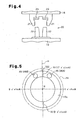
- Fig. 4 is a plan view showing the hinge mechanism shown
in Fig. 1 in a disassembled state;
- Fig. 5 is a front view illustrating the axial slide
limiting surface shown in Fig. 1;
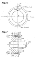
- Fig. 6 is a front view illustrating an axial slide
limiting surface of a compressor according to a second
embodiment of the present invention;
- Fig. 7 is a partial cross-sectional view illustrating a
portion including a boss of a compressor according to a third
embodiment of the present invention;
- Fig. 8 is a partial cross-sectional view illustrating a
portion including a boss of a compressor according to a fourth
embodiment of the present invention;
- Fig. 9 is a partial cross-sectional view illustrating a
portion including a boss of a compressor according to a fifth
embodiment of the present invention;
- Fig. 10 is a partial cross-sectional view illustrating a
portion including a swash plate guiding member of a compressor
according to a sixth embodiment of the present invention;
- Fig. 11 is a partial cross-sectional view illustrating a
portion including a swash plate guiding member of a compressor
according to a seventh embodiment of the present invention;
- Fig. 12 is a longitudinal cross-sectional view
illustrating a compressor according to an eighth embodiment of
the present invention;
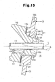
- Fig. 13 is a partial cross-sectional view illustrating a
portion including a swash plate guiding member of a compressor
according to a ninth embodiment of the present invention;
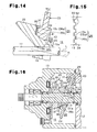
- Fig. 14 is a partial cross-sectional view illustrating a
portion including a clutch of a compressor according to a
tenth embodiment of the present invention;
- Fig. 15 is a plan view illustrating a portion including
the clutch shown in Fig. 14;
- Fig. 16 is a partial cross-sectional view illustrating a
compressor according to an eleventh embodiment of the present
invention;
- Fig. 17 is a partial cross-sectional view illustrating a
portion including a swash plate guiding member of a compressor
according to a twelfth embodiment of the present invention;
- Fig. 18 is a partial cross-sectional view illustrating
the compressor shown in Fig. 17 when the inclination angle is
minimized; and
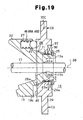
- Fig. 19 is a partial cross-sectional view illustrating a
compressor according to a modified embodiment of the present
invention.
-
DETAILED DESCRIPTION OF THE PREFERRED EMBODIMENTS
-
A first embodiment of the present invention will now be
described.
-
Fig. 1 is a longitudinal cross-sectional view
illustrating a swash plate type variable displacement
compressor 10 used in a refrigerant circuit of a vehicle air
conditioner. As shown in Fig. 1, a housing 11 of the
compressor 10 includes a cylinder block 12, a front housing
member 13, and a rear housing member 14. The front housing
member 13 is secured to one end (left end as viewed in the
drawing) of the cylinder block 12. The rear housing member 14
is secured to the other end (right end as viewed in the
drawing) of the cylinder block 12 with a valve assembly 15 in
between. In Fig. 1, the left side is (the side corresponding
to the front housing member 13) is referred to as. the front of
the compressor 10, and the right side (the side corresponding
to the rear housing member 14) is referred to as the rear of
the compressor 10, as necessary.
-
A space defined by the inner wall of the front housing
member 13 and the cylinder block 12 forms a crank chamber 16.
One end (front end) of a drive shaft 17 is rotatably supported
by the front housing member 13. The other end (rear end) of
the drive shaft 17 is rotatably supported by the cylinder
block 12. The drive shaft 17 extends frontward and rearward
in the housing 11 of the compressor 10 and through the crank
chamber 16.
-
The drive shaft 17 is connected to a drive source of the
vehicle, which is an engine (internal combustion engine) E in
this embodiment, through a power transmission mechanism PT.
The power transmission mechanism PT is a clutchless mechanism
that includes, for example, a belt and a pulley. In other
words, the power transmission mechanism PT does not have a
clutch mechanism (for example, an electromagnetic clutch) that
selectively transmits and disconnects power with external
electric control. The power transmission mechanism PT
therefore constantly transmits power. Therefore, when the
engine E is running, the drive shaft 17 constantly receives
power from the engine E and rotates around an axis L.
-
A substantially disk-shaped rotor 18 is accommodated in
the crank chamber 16. The rotor 18 is fixed to the drive
shaft 17 to rotate integrally with the drive shaft 17. A
swash plate guiding member 19, which is made of an iron-based
metal, is accommodated in the crank chamber 16. The guiding
member 19 is located rearward of the rotor 18. A boss 19a is
formed on a center of the rear side of the guiding member 19.
A shaft receiving hole 19b is formed in a central portion of
the guiding member 19 (including the boss 19a). The drive
shaft 17 extends through the shaft receiving hole 19b and
supports the guiding member 19 such that the guiding member 19
slides back and forth along the axis L of the drive shaft 17
and that the inclination angle of the guiding member 19 is
variable.
-
Specifically, the inclination angle of the guiding member
19 relative to the drive shaft 17 refers to an angle defined
by an imaginary plane perpendicular to a central axis M of the
guiding member 19 or a central axis M of the boss 19a, and an
imaginary plane perpendicular to the axis L of the drive shaft
17.
-
As shown in Figs. 1 and 4, the rotor 18 is connected to
the guiding member 19 with a hinge mechanism 20. The hinge
mechanism 20 is of a "pinless type". The hinge mechanism 20
has a pair of driving projections 21 protruding from the rear
side of the rotor and a pair of driven projections 22
protruding toward the rotor 18 from the front side of the
guiding member 19. The driven projections 22 are located
between the driving projections 21. A cam surface 23 is
formed at the proximal portion of each driving projection 21.
The distal end of the corresponding one of the driven
projection 22 slidably contacts each cam surface 23.
-
The hinge mechanism 20 thus constructed permits rotation
force of the rotor 18 to be transmitted to the guiding member
19 through one of the driving projections 21 and one of the
driven projections 22 that contacts the driving projection 21.
In a state where the distal ends of the driven projections 22
contact the cam surfaces 23, when the distal ends of the
driven projections 22 move away from the drive shaft 17, the
inclination angle of the guiding member 19 relative to the
axis L of the drive shaft 17 is increased. In contrast, when
the distal ends of the driven projections 22 move toward the
drive shaft 17, the inclination angle of the guiding member 19
relative to the axis L of the drive shaft 17 is decreased.
-
As shown in Figs. 1 and 2, a disk-shaped swash plate 24
is accommodated in the crank chamber 16. From the viewpoint
of the sliding property with the guiding member 19, the swash
plate 24 is made of a material different from that of the
guiding member 19, for example,' of a copper-based metal. A
boss receiving hole 24a is formed in a center portion of the
swash plate 24. In a section of an inner circumferential
surface 41 of the boss receiving hole 24a that corresponds to
the cylinder block 12 (rear portion), a constant diameter
portion 41a is formed. In a section of an outer
circumferential surface 43 of the boss 19a that corresponds to
the cylinder block 12 (rear portion), a constant diameter
portion 43a is formed. The boss receiving hole 24a of the
swash plate 24 receives the boss 19a of the guiding member 19.
The swash plate 24 is supported such that the constant
diameter portion 41a of the boss receiving hole 24a rotates
relative to the constant diameter portion 43a of the boss 19a
substantially around the central axis M of the boss 19a, or
around the central axis M of the swash plate 24 (the boss
receiving hole 24a), and that the constant diameter portion
41a slides on the constant diameter portion 43a back and forth
along a direction of the central axis M.
-
A slide limiting surface 19c is formed on the guiding
member 19 in an area surrounding the' proximal portion of the
boss 19a. The limiting surface 19c is formed planar and
annular shape. The limiting surface 19c lies in an imaginary
plane perpendicular to the central axis M of the guiding
member 19. Also, a snap ring 25 as a slide limiter is
attached to the guiding member 19 at a distal end (rear end)
of the boss 19a, which protrudes from the boss receiving hole
24a of the swash plate 24 toward the cylinder block 12.
-
Therefore, the swash plate 24 slides along the central
axis M in a range defined by the limiting surface 19c and the
snap ring 25. The swash plate 24 is supported by the boss 19a
and prevented from being coming off the boss 19a by the snap
ring 25. The swash plate 24 is inclined together with the
guiding member 19 so that the inclination angle with respect
to the drive shaft 17 (substantially the same as the
inclination angle of the guiding member 19 with respect to the
drive shaft 17) can be changed.
-
As shown in Fig. 1, cylinder bores 28 are formed in the
cylinder block 12 at constant angular intervals around the
axis L of the drive shaft 17. Each cylinder bore 28 extends
through the cylinder block 12 from the end face corresponding
to the front housing member 13 (front end face) to the end
face corresponding to the rear housing member 14 (rear end
face). A part of each piston 29 (a rear part that is located
at the end corresponding to the rear housing member and is
referred to as a "head") is accommodated in the corresponding
one of the cylinder bores 28. Each piston 29 is held by the
corresponding cylinder bore 28, or by the cylinder block 12,
so that the piston 29 approaches and separates from the front
end face (end face corresponding to the cylinder block 12) of
the valve assembly 15.
-
The openings of each cylinder bore 28 are closed by the
front end face of the valve assembly 15 and the corresponding
piston 29. In this manner, an enclosed space exists in each
cylinder bore, which will be referred to as a compression
chamber 30 below. Each compression chamber 30 is an enclosed
space defined in the corresponding cylinder bore 28. The
volume of each compression chamber 30 is changed as the
corresponding piston 29 slides in the cylinder bore 28.
-
A suction chamber 32 and a discharge chamber 33 are
defined by the rear end face of the valve assembly 15 and the
inner side (inner surface) of the rear housing member 14 in
the housing 11. The valve assembly 15 has suction ports 34,
which connect the compression chambers 30 with the suction
chamber 32 to permit flow of refrigerant gas between the
compression chambers 30 and the suction chamber 32. The valve
assembly 15 also has suction valve flaps 35, each of which
corresponds to one of the compression chambers 30 and opens
and closes the corresponding suction port 34. The valve
assembly 15 also has discharge ports 36, which connect the
compression chambers 30 with the discharge chamber 33 to
permit flow of refrigerant gas between the compression
chambers 30 and the discharge chamber 33. The valve assembly
15 also has discharge valve flaps 37, each of which
corresponds to one of the compression chambers 30 and opens
and closes the corresponding discharge port 36.
-
An end of each piston 29 that protrudes into the crank
chamber 16 (front end portion, which is opposite to the head)
is coupled to a peripheral portion of the swash plate 24 with
a pair of semispherical shoes 31. Rotation of the guiding
member 19 is converted into reciprocation of the pistons 29 by
the swash plate 24 and the shoes 31. Reciprocation of the
pistons 29 changes the volume of the compression chambers 30.
When each piston 29 moves from the top dead center to the
bottom dead center, refrigerant gas in the suction chamber 32
is drawn into the corresponding compression chamber 30 through
the suction ports 34 and the opened suction valve flap 35.
Refrigerant gas drawn into each compression chamber 30 is
compressed to a predetermined pressure as the piston 29 is
moved from the bottom dead center to the top dead center.
Then, the refrigerant gas is discharged to the discharge
chamber 33 through the corresponding discharge port 36 and the
opened discharge valve flap 37.
-
The inclination angle of the guiding member 19 and the
swash plate 24 is determined by the equilibrium of various
moments, such as the rotational moment caused by centrifugal
force generated when the guiding member 19 (or the guiding
member 19 and the swash plate 24) rotates, the moment caused
by reciprocation inertial force of the pistons 29, and the
moment of gas pressure acting on the front and rear end faces
of the pistons 29. The moment caused by gas pressure refers
to the moment generated based on the relationship between the
inner pressure of the compression chambers 30 and the inner
pressure of the crank chamber 16, which corresponds to a back
pressure of the pistons 29. The gas pressure moment acts to
either decrease or increase the inclination angle. A
configuration for controlling the inner pressure of the crank
chamber 16 will now be described.
-
The housing 11 has a bleed passage 38, a supply passage
39, and a control valve 40. The bleed passage 38 connects the
crank chamber 16 with the suction chamber 32 so that
refrigerant gas flows therebetween. The supply passage 39
connects the discharge chamber 33 with the crank chamber 16 so
that refrigerant gas flows therebetween. The control valve 40
is located in the supply passage 39 to adjust the opening
degree of the supply passage 39.
-
The control valve 40 has a conventional configuration
that permits the opening degree of the supply passage 39 to be
externally controlled with electricity. The control valve 40
includes an electromagnetic actuator 40a and a valve body 40b.
Electromagnetic force generated by the actuator 40a is related
to the position of the valve body 40b. Based on a command of
a control computer 60 in accordance with the cooling load and
the driving condition of the vehicle, a drive circuit 61
supplies electricity to the electromagnetic actuator 40a.
When the electricity supplied to the electromagnetic actuator
40a is increased, the control valve 40 decreases the opening
degree of the supply passage 39. When the electricity
supplied to the electromagnetic actuator 40a is decreased, the
control valve 40 increases the opening degree of the supply
passage 39. When no electricity is supplied to the
electromagnetic actuator 40a, the control valve 40 maximizes
the opening degree of the supply passage 39.
-
By adjusting its opening, the control valve 40 controls
the ratio between the flow rate of refrigerant gas (highly
pressurized gas) drawn to the crank chamber 16 from the
discharge chamber 33 through the supply passage 39, and the
flow rate of refrigerant gas supplied to the suction chamber
32 from the crank chamber 16 through the bleed passage 38,
thereby determining the inner pressure of the crank chamber
16. In accordance with the inner pressure of the crank
chamber 16 which is adjusted, in this manner, the difference
between the inner pressure of the crank chamber 16 and the
inner pressure of the compression chambers 30 with the pistons
29 in between is changed. Accordingly, the force applied to
the swash plate 24 and the guiding member 19 by the pistons 29
is changed. This, in turn, changes the inclination angle of
the guiding member 19 and the swash plate 24. As a result,
the stroke of each piston 29, that is, the displacement of the
compressor 10, is controlled. Specifically, the displacement
of the compressor 10 is controlled in the following manner.
-
When the inner pressure of the crank chamber 16 is
lowered as the opening degree of the control valve 40 (the
supply passage 39) is reduced, the inclination angle of the
guiding member 19 and the swash plate 24 is increased. This
lengthens the stroke of each piston 29 and the displacement of
the compressor 10 is increased, accordingly. In contrast,
when the inner pressure of the crank chamber 16 is increased
as the opening degree of the control valve 40 is increased,
the inclination angle of the guiding member 19 and the swash
plate 24 is decreased. This shortens the stroke of each
piston 29 and the displacement of the compressor 10 is
decreased, accordingly. When the opening degree of the
control valve 40 is maximized, the inclination angle of the
guiding member 19 and the swash plate 24 is minimized (zero
degrees or an minute angle close to zero degrees, for example,
an angle in a range between 0° and approximately 3°). In this
state, the displacement of the compressor 10 is minimized (see
Fig. 3).
-
When an occupant commands to turn off the air
conditioning (for example, turns an air conditioner switch
(not shown) off), or when the vehicle is rapidly accelerated
(for example, when an acceleration pedal (not shown) is
depressed by an degree greater than a predetermined amount),
the control computer 60 commands the drive circuit 61 to stop
supplying electricity to the control valve 40. Therefore, the
opening degree of the control valve 40 is maximized and the
displacement of the compressor 10 is minimized. That is, the
compressor 10 is in an "OFF operation". Accordingly, the load
on the engine E (load for driving the compressor 10) is
reduced. Thus, for example, the fuel economy of the engine E
and the acceleration performance of the vehicle are improved.
-
As shown in Figs. 1 to 3, a clutch 26 is located between
the guiding member 19 and the swash plate 24. The clutch 26
switches between an engaged state to cause the guiding member
19 and the swash plate 24 to rotate integrally, and a
disengaged state to permit the guiding member 19 and the swash
plate 24 to rotate relative to each other. The clutch 26 will
now be described.
-
The clutch 26 is a cone clutch, which is a friction
clutch. The clutch 26 includes a driving clutch surface 26a
and a driven clutch surface 26b. The driving clutch surface
26a is located on an outer circumferential surface 43 of the
boss 19a of the guiding member 19 and forms part of the outer
circumferential surface 43. The driven clutch surface 26b is
located on an inner circumferential surface 41 of the boss
receiving hole 24a of the swash plate 24 and forms part of the
inner circumferential surface 41.
-
The driving clutch surface 26a is adjacent (connected) to
the constant diameter portion 43a at a front portion as viewed
in a direction along the central axis M of the boss 19a (the
proximal portion of the boss 19a). The driving clutch surface
26a is shaped as a cone with a central axis coinciding with
the central axis M. Specifically, a section of the driving
clutch surface 26a that is closer to the constant diameter
portion 43a (a section corresponding to the distal end of the
boss 19a) has a smaller diameter. A section of the driving
clutch surface 26a that corresponds to the proximal portion of
the boss 19a has a larger diameter. The boundary between the
driving clutch surface 26a and the constant diameter portion
43a is machined to form a concave surface so that the constant
diameter portion 43a is smoothly connected to the driving
clutch surface 26a. This prevents stress being concentrated
on the boundary.
-
The driven clutch surface 26b is adjacent (connected) to
the constant diameter portion 41a at a front portion as viewed
in a direction along the central axis M of the swash plate 24
(the proximal portion of the boss 19a). The driven clutch
surface 26b is shaped as a cone with a central axis coinciding
with the central axis M. Specifically, a section of the
driven clutch surface 26b that is closer to the constant
diameter portion 41a (a section corresponding to the distal
end of the boss 19a) has a smaller diameter. A section of the
driven clutch surface 26b that corresponds to the proximal
portion of the boss 19a has a larger diameter. The boundary
between the driven clutch surface 26b and the constant
diameter portion 41a is machined to be a convex surface so
that the boundary does not contact the outer circumferential
surface 43 in its edge.
-
To permit the clutch 26 to operate in a favorable manner
(for example, to provide the clutch 26 in a narrow space
between the boss 19a and the boss receiving hole 24a while
securing a sufficient clutch capacity), the angle a (see Fig.
2) of the driving clutch surface 26a and the driven clutch
surface 26b relative to the central axis M is set preferably
in a range between 5° and 20°, more preferably in a range
between 10° and 15°.
-
When the swash plate 24 slides relative to the guiding
member 19 in a direction along the central axis M, the driven
.clutch surface 26b of the clutch 26 approaches or separates
from the driving clutch surface 26a. A state in which the
driven clutch surface 26b contacts the driving clutch surface
26a is the engaged state of the clutch 26. When the clutch 26
is engaged, rotational force of the guiding member 19 is
transmitted to the swash plate 24 substantially at 100%, which
causes the swash plate 24 to rotate integrally with the
guiding member 19 (see Fig. 2).
-
A state in which the driven clutch surface 26b is away
from the driving clutch surface 26a is the disengaged state of
the clutch 26. When the clutch 26 is disengaged, little or no
rotational force of the guiding member 19 is transmitted to
the swash plate 24, which permits the swash plate 24 and the
guiding member 19 to rotate relative to each other. In other
words, the swash plate 24 slips on the guiding member 19 (see
Fig. 3).
-
That is, the clutch 26 is switched from the disengaged
state of Fig. 3 to the engaged state of Fig. 2 when the swash
plate 24 slides on the guiding member 19 in one direction
(towards the limiting surface 19c) along the central axis M.
Also, the clutch 26 is switched from the engaged state of Fig.
2 to the disengaged state of Fig. 3 when the swash plate 24
slides on the guiding member 19 in the other direction
(towards the cylinder block 12) along the central axis M.
-
When the clutch 26 is switched from the disengaged state
to the engaged state, the swash plate 24 is slid by
compression reaction force CS acting on the swash plate 24
through the pistons 29 as refrigerant gas is compressed.
Also, when the clutch 26 is switched from the engaged state to
the disengaged state, the swash plate 24 is slid by force
(urging force) of the coil springs 27 located between the
guiding member 19 and the swash plate 24. Hereinafter,
springs 27 and the structure including the spring 27 will be
described.
-
As shown in Fig. 2, spring holes 46 (only one is shown in
Fig. 2) for accommodating the spring 27 are formed in the
limiting surface 19c of the guiding member 19. The transverse
cross section of the spring hole 46 is substantially circular.
The axis of the circle of the hole 46 is parallel to the
central axis M of the guiding member 19. As shown in Fig. 5,
a portion on the swash plate 24 that corresponds to a top dead
center is denoted as TDC, which portion coincides with a
center point of the curvature of the shoes 31 corresponding to
the piston 29 at the top dead center. An imaginary plate
containing the top dead center portion TDC and the central
axis M of the swash plate 24 is denoted as an imaginary plane
H. One of the spring holes 46 (spring hole 46A) is located in
one of the areas of the swash plate 24 divided by the
imaginary plane H (a right area as viewed in the drawing).
The other spring hole 46 (spring hole 46B) is located in the
other area (left area as viewed in the drawing). The spring
hole 46A and the spring hole 46B are symmetrical with respect
to the imaginary plane H.
-
Specifically, the state of Fig. 5, or the state when the
limiting surface 19c is viewed from the front, is regarded as
a dial of a clock (in other words, the central axis M is
regarded as the axis of a clock). Sections of lines at
intersections of the annular limiting surface 19c and the
imaginary plane H are referred to as line sections X1, X2.
The line section X1, which is located at the side of the top
dead center portion TDC of the swash plate 24 (upper side as
viewed in the drawing), corresponds to twelve o'clock. The
line section X2, which is located at a side opposite from the
top dead center portion TDC (lower side as viewed in the
drawing), corresponds to six o'clock.
-
The spring hole 46A (specifically the center of the
opening of the spring hole 46A) is located in a range from
twelve o' clock to three o' clock in the clockwise direction
on the limiting surface 19c (preferably in a range from one o'
clock to two o' clock). Also, the spring hole 46B
(specifically the center of the opening of the spring hole
46B) is located in a range from nine o'clock to twelve o'clock
in the clockwise direction on the limiting surface 19c
(preferably in a range from ten o'clock to eleven o' clock).
That is, the springs 27 accommodated in the spring holes 46A,
46B are arranged to apply force in a concentrated and intense
manner to an area near the top dead center portion TDC on the
swash plate 24 around the central axis M. At the area, the
compression reaction force CS acts strongly.
-
As shown in Fig. 2, a ball 47, which functions as bearing
and a thrust bearing, is held by each of the spring holes 46A,
46B. Each ball 47 is urged toward the swash plate 24 by the
force of the corresponding spring 27. Part of each ball 47
projects from the spring hole 46A, 46B, or from the limiting
surface 19c, toward the swash plate 24. Around the opening of
the boss receiving hole 24a on the front face of the swash
plate 24, a roll groove 48 is formed to correspond to the
limiting surface 19c of the guiding member 19. The roll
groove 48 is formed annular around the central axis M. The
transverse cross section of the roll groove 48 is
substantially semicircular.
-
As described above, each ball 47,which is urged by the
corresponding spring 27, contacts the inner surface of the
roll groove 48. That is, each spring 27 applies its force to
the swash plate 24 through the corresponding ball 47 and the
inner surface of the roll groove 48. Also, when the guiding
member 19 and the swash plate 24 rotate relative to each other
in the disengaged state of the clutch 26, the balls 47 roll on
the inner surface of the roll groove 48 along the
circumferential direction of the roll groove 48. That is, the
balls 47 are located between the springs 27 and the swash
plate 24, which rotates relative to the guiding member 19 in
the disengaged state of the clutch 26.
-
Switching of the clutch 26 will now be described.
-
In a state shown in Fig. 3, that is, when the compressor
10 is in the OFF operation, the stroke of the pistons 29 is
zero or a value close to zero. Therefore, the compression
reaction force CS applied to the swash plate 24 through the
pistons 29 is less than a predetermined value. In this state,
the force of the springs 27 acts dominantly to determine the
position of the swash plate 24 relative to the guiding member
19 (the boss 19a) in a direction along the central axis M.
-
Therefore, the swash plate 24 is moved by the force of
the springs 27 to a position contacting the snap ring 25
against the compression reaction force CS, the clutch 26 is
caused to the disengaged state. In this state, the swash
plate 24 and the guiding member 19 rotate relative to each
other. That is, the swash plate 24 slips on the guiding
member 19, and the rotation speed of the swash plate 24 is
lower than the rotation speed of the guiding member 19. As a
result, the mechanical loss between the swash plate 24 and the
shoes 31 is further reduced. Accordingly, the load of the
compressor 10, which acts on the engine E, is further reduced.
-
Since the load of the compressor 10 on the engine E is
further reduced, the fuel economy of the engine E and the
acceleration performance of the vehicle are further improved.
Also, since the generation of frictional heat at contacting
portions of the swash plate 24 and the shoes 31 is suppressed,
a lip seal for sealing an end portion of the drive shaft 17
and a bearing supporting the shaft end portion are prevented
from being degraded by heat. This improves the reliability of
the compressor 10.
-
In the OFF operation state of the compressor 10, the
swash plate 24 is slightly inclined relative to the axis L of
the drive shaft 17, and the pistons 29 are reciprocated with a
very small stroke. This causes refrigerant gas to be
discharged to the discharge chamber 33 from the compression
chambers 30. The refrigerant gas is then supplied to the
crank chamber 16 from the discharge chamber 33 through the
supply passage 39 and the control valve 40. The refrigerant
gas in the crank chamber 16 is supplied to the suction chamber
32 through the bleed passage 38, and then drawn into the
compression chambers 30 from the suction chamber 32. In this
manner, when the compressor 10 is in the OFF operation,
refrigerant gas circulates within the compressor 10 and passes
through the control valve 40.
-
If the opening degree of the control valve 40 is less
than the fully opened state (by starting the supply of
electricity to the electromagnetic actuator 40a of the control
valve 40), the flow rate of refrigerant gas supplied to the
crank chamber 16 is decreased. Accordingly, the compression
reaction force CS is relatively increased. Also, when the
flow rate of refrigerant gas supplied to the crank chamber 16
decreases, the inclination angle of the swash plate 24 is
increased, so that the displacement of the compressor 10 is
increased from the minimum displacement (leaves the OFF
operation and shifts to "an ON operation"). Therefore, the
compression reaction force CS applied to the swash plate 24. is
greater than the predetermined value. In this state, the
compression reaction force CS acts dominantly to determine the
position of the swash plate 24 relative to the guiding member
19 (the boss 19a) in a direction along the central axis M.
-
Accordingly, the swash plate 24 is moved by the
compression reaction force CS to a position where the driven
clutch surface 26b contacts the driving clutch surface 26a
against to the force of the springs 27. This engages the
clutch 26, and the swash plate 24 and the guiding member 19
start rotate integrally. If the opening degree of the control
valve 40 is changed in a state where the swash plate 24 and
the guiding member 19 rotate integrally, that is, in the on
operating state of the compressor 10, the inclination angle of
the guiding member 19 and the swash plate 24 is changed.
-
At this time, since centrifugal force acts on the guiding
member 19 and the swash plate 24 which rotates integrally with
the guiding member 19, the inertial force due to reciprocation
of the pistons 29 is cancelled. This permits the inclination
angle of the guiding member 19 and the swash plate 24 to be
easily changed. Particularly, when the compressor 10 is
operating at a high speed (when the drive shaft 17 is rotating
at a high speed), that is, the inertial force of the pistons
29 is great, the advantage of facilitating changes in the
inclination angle of the guiding member 19 and the swash plate
24 is remarkable.
-
When the control valve 40 is fully opened during the ON
operation of the compressor 10 (when the supply of electricity
to the electromagnetic actuator 40a of the control valve 40 is
stopped), the compressor 10 shifts to the OFF operation and
the clutch 26 is disengaged.
-
The above embodiment provides the following advantages.
- (1) As described above, engaging the clutch 26 improves
the displacement control performance of the compressor 10, and
disengaging the clutch 26 reduces the mechanical loss between
the swash plate 24 and the shoes 31. Therefore, when, for
example, designing the compressor 10, the dilemma accompanying
the prior art is avoided.
- (2) The boss 19a of the guiding member 19 supports the
swash plate 24 at the boss receiving hole 24a. The swash
plate 24, which receives the boss 19a at the boss receiving
hole 24a formed in the center portion of the swash plate 24,
is stably supported by the boss 19a. This permits the swash
plate 24 to smoothly slide in a direction along the central
axis M.
- (3) When the clutch 26 is switched from the disengaged
state to the engaged state, the swash plate 24 is slid by
compression reaction force CS acting on the swash plate 24
through the pistons 29 as refrigerant gas is compressed.
Therefore, the clutch 26 is automatically switched from the
engaged state to the disengaged state and from the disengaged
state to the engaged state according to the operating
condition of the compressor 10. Therefore, no special
external control means for directly controlling the clutch 26
is required. This simplifies the structure of the compressor
10.
- (4) When the clutch 26 is switched from the engaged state
to the disengaged state, the swash plate 24 is slid by the
force of the springs 27. Therefore, when in the engaged
state, the clutch 26 is reliably switched to the disengaged
state by the force of the springs 27.
- (5) The balls (bearing, thrust bearings) 47 are located
between the guiding member 19 and the swash plate 24. The
balls 47 support the swash plate 24 such that the swash plate
24 is rotatable relative to the guiding member 19. Therefore,
when the guiding member 19 and the swash plate 24 rotate
relative to each other, that is, when the clutch 26 is in the
disengaged state, the mechanical loss between the guiding
member 19 and the swash plate 24 is further reduced.
- (6) The balls 47 (bearing, a thrust bearing) are located
between the springs 27 and the swash plate 24, which rotates
in the disengaged state of the clutch 26. Therefore, when the
guiding member 19 and the swash plate 24 rotate relative to
each other, that is, when the clutch 26 is in the disengaged
state, the mechanical loss between the swash plate 24 and the
springs 27 is further reduced. This further reduces the load
of the compressor 10 acting on the engine E.
- (7) The roll groove 48, in which the balls 47 roll, is
formed on the swash plate 24. The roll groove 48 has a
semicircular transverse cross-section. Therefore, compared to
a case where balls roll on a flat surface of a swash plate,
the surface pressure between each ball 47 and a section of the
roll groove 48 contacting the ball 47 is small. As a result,
the mechanical loss between the swash plate 24 and the springs
27 is further effectively reduced. Accordingly, the load of
the compressor 10, which acts on the engine E, is further
reduced.
- (8) The springs 27 are configured to apply force in a
concentrated and intense manner to an area near the top dead
center portion TDC on the swash plate 24 around the central
axis M. That is, in the area of the swash plate 24 near the
top dead center portion TDC receives the compression reaction
force CS in a concentrated and intense manner. Therefore,
when the swash plate 24 slides as the clutch 26 is switched
from the engaged state to the disengaged state, the movement
of the top dead center portion TDC of the swash plate 24 is
hindered by the strong compression reaction force CS compared
to other portions. Also, when the swash plate 24 slides as
the clutch 26 is switched from the disengaged state to the
engaged state, the top dead center portion TDC of the swash
plate 24 is excessively moved by the strong compression
reaction force CS compared to other portions. That is, since
the compression reaction force CS acts on the top dead center
portion TDC in a concentrated manner, the inclination of the
swash plate 24 relative to the central axis M is facilitated
when the swash plate 24 is sliding.
Therefore, if the force of the springs 27 is controlled
to act on the top dead center portion TDC in a concentrated
manner against the strong compression reaction force CS as in
the above embodiment, the sliding attitude of the swash plate
24 is stabilized (the swash plate 24 is prevented from being
inclined relative to the central axis M). This permits the
swash plate 24 to smoothly slide; and thus permits the clutch
26 to smoothly and reliably switch the state.
- (9) The clutch 26 is in the engaged state when the
driving clutch surface 26a formed on the guiding member 19
contacts the driven clutch surface 26b formed on the swash
plate 24. Therefore, no medium connecting the driving clutch
surface and the driven clutch surface is required (for
example, an electromagnetic powder clutch uses powder as the
medium). Therefore, the structure of the clutch 26 is
simplified and its size is reduced.
- (10) The driving clutch surface 26a is formed on the
outer circumferential surface 43 of the boss 19a, and the
driven clutch surface 26b is formed on the inner
circumferential surface 41 of the boss receiving hole 24a..
That is, part of the outer circumferential surface 43 of the
boss 19a is used as the driving clutch surface 26a, and part
of the inner circumferential surface 41 of the boss receiving
hole 24a is used as the driven clutch surface 26b. Thus, for
example, when compared to a case where the driving clutch
surface 26a and the driven clutch surface 26b are located
outside of the boss receiving hole 24a, that is, when compared
to a case where the driving clutch surface 26a and the driven
clutch surface 26b are independently formed, the structure of
the guiding member 19 and the swash plate 24 is simplified and
the size is reduced.
- (11) The clutch 26 is a friction clutch. Thus, the
shapes of the driving clutch surface 26a and the driven clutch
surface 26b are simple, which simplifies the structure of the
clutch 26. Also, a little sliding of the swash plate 24
relative to the guiding member 19 permits the clutch 26 to
switch between the engaged state and the disengaged state.
Therefore, the sliding of the swash plate 24 does not
adversely affects the efficiency of the compressor 10. For
example, the top clearance (the distance'between a piston 29
at the top dead center and the valve assembly 15), which
degrades the efficiency of the compressor 10 when the top
clearance is increased, is not increased. Further, the size
of the compressor 10 is reduced.
During the ON operation of the compressor 10, adhesion
between the swash plate 24 and the shoes 31 increases the
torque required for rotating the swash plate 24. In this
case, the clutch 26, which is a friction clutch, exerts a
torque limiting function and slips the driving clutch surface
26a and the driven clutch surface 26b on each other.
Therefore, the swash'plate 24 is not forced to rotate when the
swash plate 24 receives an excessive torque, so the belt and
other members of the power transmission mechanism PT are not
damaged. Therefore, the power transmission mechanism PT does
not need to have a dedicated torque limiter, which simplifies
the structure of the compressor 10. - (12) The clutch 26 is a cone clutch. Even if the radial
size of the cone clutch is reduced, a large area is secured
for the driving clutch surface 26a and the driven clutch
surface 26b.. Therefore, as in the above embodiment, it is
possible to form the driving clutch surface 26a on the outer
circumferential surface 43 of the boss 19a and the driven
clutch surface 26b on the inner circumferential surface 41 of
the boss receiving hole 24a, and to secure a great capacity of
the clutch 26.
Fig. 6 illustrates a compressor according to a second
embodiment, which is a modification of the first embodiment.
Hereafter, only the components different from those of
the compressor according to the first embodiment are
explained. The same, equivalent, or similar components are
given the same numbers and detailed explanations are omitted.The compressor of the second embodiment is the same as
the compressor of the first embodiment except that the
compressor of the second embodiment has one spring hole 46,
one spring 27, and one ball 47. The spring hole 46 is
arranged such that the central axis of the spring hole 46 is
located on the imaginary plane H. That is, the spring hole 46
(specifically, the center of the opening of the spring hole
46) corresponds to twelve o'clock on the limiting surface 19c
of the guiding member 19.The spring hole 46 may be misaligned clockwise or
counterclockwise from twelve o' clock. Particularly, if the
drive shaft 17 rotates clockwise as viewed in Fig. 6, the
spring hole 46, or the spring 27 accommodated in the spring
hole 46, is preferably provided in a range from twelve o'clock
to three o'clock in the clockwise direction, where the
compression reaction force CS strongly acts (more preferably
in a range from one o'clock to two o'clock in the clockwise
direction). In contrast, if the drive shaft 17 rotates
counterclockwise as viewed in Fig. 6, the spring hole 46, or
the spring 27 accommodated in the spring hole 46, is
preferably provided in a range between nine o'clock to twelve
o'clock in the clockwise direction, where the compression
reaction force CS strongly acts (preferably in a range from
ten o'clock to eleven o'clock in the clockwise direction). The compressor according to the second embodiment has the
same advantages (1) to (12) of the compressor according to the
first embodiment. In addition, the compressor according to
the second embodiment provides the following advantage (13). - (13) Since the number of each of the spring hole 46, the
spring 27, and the ball (bearing, thrust bearing) 47 is one,
the structure of the compressor 10 is simplified.
Fig. 7 illustrates a compressor according to a third
embodiment, which is a modification of the first embodiment.
Fig. 8 illustrates a compressor according to a fourth
embodiment, which is a modification of the first embodiment.The compressors according to the third and fourth
embodiments are the same as the compressor according to the
first embodiment except that a radial bearing 71 is located
between the guiding member 19 and the swash plate 24. The
radial bearing 71 supports the swash plate 24 such that the
swash plate 24 rotate relative to the guiding member 19 around
the central axis M and slides in a direction along the central
axis M.Particularly, in the compressor according to the third
embodiment (Fig. 7), the radial bearing 71 is a linear ball
bearing. The linear ball bearing includes an outer ring 72
and a ball holder 73. The outer ring 72 is fixed to the
constant diameter portion 41a of the boss receiving hole 24a,
for example, by press fitting. The ball holder 73 is located
inside of the outer ring 72 and holds two or more
circumferential rows of balls 73a. Each ball 73a in the ball
holder 73 contacts the inner circumferential surface of the
outer ring 72 and the constant diameter portion 43a of the
outer circumferential surface 43 of the boss 19a. Free
rolling of the balls 73a permits the guiding member 19 and the
swash plate 24 to rotate relative to each other and slide in a
direction along the central axis M relative to each other.In the compressor according to the fourth embodiment
(Fig. 8), the radial bearing 71 is a plain bearing. The plain
bearing includes an outer cylinder 75 and an inner cylinder
76. The outer cylinder 75 is fixed to the constant diameter
portion 41a of the inner circumferential surface 41 of the
boss receiving hole 24a, for example, by press fitting. The
inner cylinder 76 is fixed to the constant diameter portion
43a of the outer circumferential surface 43 of the boss 19a,
for example, by press fitting. The outer cylinder 75 and the
inner cylinder 76 are both made of material having a superior
sliding property. Relative rotation and movement in the axial
direction of the outer cylinder 75 and the inner cylinder 76,
or relative rotation and relative sliding in a direction along
the central axis M of the guiding member 19 and the swash
plate 24 are smoothly performed.The compressors according to the third and fourth
embodiments have the same advantages (1) to (12) of the
compressor according to the first embodiment. In addition,
the compressors according to the third and fourth embodiments
provide the following advantage (14).
- (14) The radial bearing 71 further reduces the mechanical
loss between the guiding member 19 and the swash plate 24 when
the clutch 26 is in the disengaged state. For example, the
load of the compressor that acts on the engine E is further
reduced. Further, when the clutch 26 is switched, the swash
plate 24 is slid smoothly. Further, when the clutch 26
performs torque limiting or is in the disengaged state, the
outer circumferential surface 43 of the boss 19a and the inner
circumferential surface 41 of the boss receiving hole 24a are
prevented from being worn.
Fig. 9 illustrates a compressor according to a fifth
embodiment, which is a modification of the first embodiment.The compressor of the fifth embodiment is the same as the
compressor of the first embodiment except that the compressor
of the fifth embodiment has oil supply portion 77. The oil
supply portion 77 supplies lubricant oil (refrigeration oil)
to a space between the guiding member 19 and the swash plate
24 when the guiding member 19 and the swash plate 24 rotate
relative to each other. The oil supply portion 77 will now be
described.The oil supply portion 77 has an oil supply hole 78
formed in the guiding member 19 and a reservoir groove 79
formed on the inner circumferential surface 41 of the boss
receiving hole 24a of the swash plate 24. The reservoir
groove 79 is linearly formed with a curved part, and extends
substantially along the central axis M (in a direction
frontward and backward). The reservoir groove 79 extends from
the constant diameter portion 41a to the driven clutch surface
26b. The oil supply hole 78 has an outlet 78a of lubricant
oil. The outlet 78a opens to (is connected to) the reservoir
groove 79 on the outer circumferential surface 43 of the boss
19a. The oil supply hole 78 has an inlet 78b of lubricant
oil. The inlet 78b opens to (is connected to) the crank
chamber 16 at a position that is closer to the drive shaft 17
than the outlet 78a on the rear side of the guiding member 19.
Specifically, the inlet 78b opens to the crank chamber 16 at a
position on the inner circumferential surface of the boss 19a.Therefore, lubricant oil drawn to the inlet 78b of the
oil supply hole 78 from the crank chamber 16 is moved to the
outlet 78a, which is farther from the drive shaft 17 than the
inlet 78b, by centrifugal force generated as the guiding
member 19 rotates. The lubricant oil is then supplied to the
reservoir groove 79. The lubricant oil supplied to the
reservoir groove 79 spreads (flows) in the groove 79
substantially along the central axis M. Further, as the
guiding member 19 and the swash plate 24 rotate relative to
each other, the lubricant oil spreads in a wide area.between
the outer circumferential surface 43 of the boss 19a and the
inner circumferential surface 41 of the boss receiving hole
24a.The compressor according to the fifth embodiment has the
same advantages (1) to (12) of the compressor according to the
first embodiment. In addition, the compressor according to
the fifth embodiment provides the following advantages (15) to
(19).
- (15) The oil supply portion 77 supplies lubricant oil to
a space between the guiding member 19 and the swash plate 24
when the guiding member 19 and the swash plate 24 rotate
relative to each other. Therefore, when the guiding member 19
and the swash plate 24 rotate relative to each other, that is,
when the clutch 26 is performing torque limiting or in the
disengaged state, the mechanical loss between the guiding
member 19 and the swash plate 24 is further reduced. Further,
for example, the load of the compressor that acts on the
engine E is reduced.
- (16) The oil supply portion 77 supplies lubricant oil to
a space between the driving clutch surface 26a and the driven
clutch surface 26b when the guiding member 19 and the swash
plate 24 rotate relative to each other. Therefore, when the
clutch 26 is performing torque limiting or in the disengaged
state, the mechanical loss between the driving clutch surface
26a and the driven clutch surface 26b is further reduced.
Particularly, when the clutch 26 is performing torque
limiting, wear of the driving clutch surface 26a and the
driven clutch surface 26b is suppressed.
- (17) The oil supply portion 77 supplies lubricant oil to
a space between the outer circumferential surface 43 of the
boss 19a and the inner circumferential surface 41 of the boss
receiving hole 24a when the guiding member 19 and the swash
plate 24 rotate relative to each other. Therefore, when the
guiding member 19 and the swash plate 24 rotate relative to
each other, that is, when the clutch 26 is performing torque
limiting or in the disengaged state, the mechanical loss
between the outer circumferential surface 43 of the boss 19a
and the inner circumferential surface 41 of the boss receiving
hole 24a is further reduced. Further, the load of the
compressor acting on the engine E is reduced. Further, when
the clutch 26 is switched, the swash plate 24 is slid
smoothly.
- (18) The oil supply portion 77 has the oil supply hole
78. The oil supply hole 78 uses centrifugal force generated
when the guiding member 19 rotates to move lubricant oil from
the inlet 78b to the outlet 78a. Since lubricant oil is
supplied by using centrifugal force, the structure of the oil
supply portion 77 is simplified to have only a passage.
- (19) The oil supply portion 77 has the reservoir groove
79 to which lubricant oil is supplied from the oil supply hole
78. The reservoir groove 79 is formed on the inner
circumferential surface 41 of the boss receiving hole 24a to
extend substantially along the central axis M. This permits
lubricant oil to spread in an wide area between the outer
circumferential surface 43 of the boss 19a and the inner
circumferential surface 41 of the boss receiving hole 24a.
Therefore, mechanical loss between the outer circumferential
surface 43 of the boss 19a and the inner circumferential
surface 41 of the boss receiving hole 24a is further
effectively reduced.
Fig. 10 illustrates a compressor according to a sixth
embodiment, which is a modification of the first embodiment.
Fig. 11 illustrates a compressor according to a seventh
embodiment, which is a modification of the first embodiment.The compressors according to the sixth and seventh
embodiments are the same as the compressor according to the
first embodiment except that the clutch 26, the driving clutch
surface 26a, and the driven clutch surface 26b are located
outside of the boss receiving hole 24a. Therefore, almost the
entire inner circumferential surface 41 of the boss receiving
hole 24a is the constant diameter portion 41a, and almost the
entire outer circumferential surface 43 of the boss 19a is the
constant diameter portion 43a.In the sixth embodiment (Fig. 10), a cylindrical surface
forming projection 80 projects from the rear side of the
guiding member 19. The surface forming projection 80 is
located radially outside of the limiting surface 19c. The
inner circumferential surface of the surface forming
projection 80 functions as the driving clutch surface 26a. A
driven clutch surface 26b is formed in a peripheral portion of
the front side of the swash plate 24 that is radially outside
of the roll groove 48.In the seventh embodiment (Fig. 11), a cylindrical
surface forming projection 81 projects from the front side of
the swash plate 24. The surface forming projection 81 is
located radially outside of the roll groove 48. The inner
circumferential surface of the surface forming projection 81
functions as the driven clutch surface 26b. A driving clutch
surface 26a is formed in a peripheral portion of the rear side
of the guiding member 19 that is radially outside of the
limiting surface 19c.The compressors according to the sixth and seventh
embodiments have the same advantages (1) to (9), (11), and
(12) of the compressor according to the first embodiment. In
addition, the compressors according to the sixth and seventh
embodiments provide the following advantage (20).
- (20) The driving clutch surface 26a and the driven clutch
surface 26b are located outside of the boss receiving hole
24a. That is, the driving clutch surface 26a is formed
separately from the outer circumferential surface 43 of the
boss 19a, and the driven clutch surface 26b is formed
separately from the inner circumferential surface 41 of the
boss receiving hole 24a.
Therefore, the structure of the clutch 26 (for example,
the shapes and the measurements of the driving clutch surface
26a and the driven clutch surface 26b) is not significantly
affected by the arrangement, the measurements, and the shapes
of the boss 19a (the outer circumferential surface 43) and the
boss receiving hole 24a (the inner circumferential surface
41). This adds to the flexibility of design of the clutch 26.
Accordingly, a wide area can be easily secured for the area of
the driving clutch surface 26a and the driven clutch surface
26b. This increases the capacity of the clutch 26.
Increasing the capacity of the clutch 26 reliably suppresses
the slipping between the guiding member 19 and the swash plate
24 when the clutch 26 is engaged. This, for example, permits
the compressor to maintain a favorable displacement control
performance.Since the driving clutch surface 26a and the driven
clutch surface 26b are located outside the boss receiving hole
24a, substantially the entire inner circumferential surface 41
of the boss receiving hole 24a is used as the constant
diameter portion 41a and substantially the entire outer
circumferential surface 43 of the boss 19a is used as the
constant diameter portion 43a. Therefore, during the OFF
operation of the compressor 10, the swash plate 24 is stably
supported by the boss 19a. Thus, for example, noise and
vibration due to chattering of the swash plate 24 and
undesirable fluctuations of stroke of the pistons 29 are
suppressed. Further, when the clutch 26 is switched, the
swash plate 24 is slid smoothly. That is, switching of the
clutch 26 is reliably and smoothly performed.Fig. 12 illustrates a compressor according to an eighth
embodiment, which is a modification of the first embodiment.The compressor 10 according to the eight embodiment is
the same as the compressor 10 according to the first
embodiment except for a first rotation speed sensor (swash
plate rotation speed sensor) 85 for detecting the rotation
speed of the swash plate 24, a second rotation speed sensor 86
for detecting the rotation speed of the guiding member 19, and
an indicator 87,.which is, for example, a lamp.The first rotation speed sensor 85 includes a magnet 85a
embedded in the outer edge of the swash plate 24 and a pickup
coil 85b that is attached to the housing 11 and located in the
crank chamber 16. When the magnet 85a passes by the pickup
coil 85b, and a magnetic flux is generated, the pickup coil
85b generates pulses corresponding to the rotation speed of
the swash plate 24 due to electromagnetic induction, and sends
the pulses to the control computer 60.The second rotation speed sensor 86 is connected to a
computer (not shown) for controlling, for example, the engine
E. The computer uses the second rotation speed sensor 86 to
obtain the rotation speed of the engine E (output shaft), in
other words, to obtain a physical quantity related to the
rotation speed of the guiding member 19. The computer for
controlling the engine E sends information regarding the
rotation speed detected by the second rotation speed sensor 86
to the control computer 60, which is communicatively connected
to the engine computer. The control computer 60 obtains the
rotation speed of the drive shaft 17, or the rotation speed of
the guiding member 19, based on the rotation speed of the
engine E and a predetermined pulley ratio of the power
transmission mechanism PT.The control computer 60 judges whether the rotation speed
of the swash plate 24 is lower than the rotation speed of the
guiding member 19 (for example, whether the rotation speed of
the swash plate 24 is equal to or lower than a predetermined
value) when the clutch 26 is engaged, that is, when the
computer 60 is commanding the drive circuit 61 to supply
electricity to the control valve 40. This process corresponds
to a slip judging portion. In the engaged state of the clutch
26, the rotation speed of the swash plate 24 falls below the
rotation speed of the guiding member 19, that is, the swash
plate 24 slips relative to the guiding member 19 (the clutch
26 is unable to transmit power at 100%) when the swash plate
24 and the shoes 31 adhere to each other and the torque
required for rotating the swash plate 24 is unduly increased.When the outcome of the above judgment is positive, the
control computer 60 commands the drive circuit 61 to stop the
supply of electricity to the control valve 40, thereby
disengaging the clutch 26.. This process corresponds to clutch
controller. This frees the driving clutch surface 26a and the
driven clutch surface 26b from a harsh sliding environment,
and thus reduces deterioration due to wearing. Also, the
displacement of the compressor 10 is minimized when the clutch
26 is disengaged. In this state, the stroke of the pistons 29
is minimized, and the torque required for wobbling the swash
plate 24 is decreased to a low level. Therefore, the load on
the guiding member 19 when the swash plate 24 wobbles is
reduced.When the clutch 26 is disengaged, that is, when the
computer 60 is commanding the drive circuit 61 to stop
supplying electricity to the control valve 40, the control
computer 60 judges whether the rotation speed of the swash
plate 24 is more than a reference rotation speed that is
stored in a RAM in advance . This process corresponds to an
abnormality judging portion. In the disengaged state of the
clutch 26, the rotation speed of the swash plate 24 surpasses
the reference rotation speed if, for example, there is an
abnormality in the clutch 26 and the transmission of power is
not completely stopped. When the result of the judgment is
positive, the control computer 60 stores an occurrence of the
abnormality in the RAM (this process corresponds to memory
portion) and causes the indicator (lamp) 87, which has been
off, to light up or blink (alternatively, turns off the
lighting indicator 87 or causes the lighting indicator 87 to
blink or change the lighting color).The compressor according to the eighth embodiment has the
same advantages (1) to (12) of the compressor according to the
first embodiment. In addition, the compressor according to
the eighth embodiment provides the following advantages (21)
and (22).
- (21) When the clutch 26 starts slipping while being
engaged, the computer 60 disengages the clutch 26. Therefore,
the guiding member 19 does not need to rotate the swash plate
24. This prevents rotation of the guiding member 19, that is,
rotation of the drive shaft 17, from being locked. Therefore,
the power transmission mechanism PT does not need to have a
dedicated torque limiter, which simplifies the structure of
the compressor 10.
Particularly in this embodiment, the clutch 26 is
disengaged when the displacement of the compressor 10 is
minimized. Therefore, the torque required for wobbling the
swash plate 24 is reduced when the swash plate 24 is adhered
to the shoes 31. This further prevents adhesion between the
swash plate 24 and the shoes 31 from affecting the guiding
member 19. Also, since the swash plate 24 is scarcely caused
to wobble or not caused to wobble at all, adhesion between the
swash plate 24 and the shoes 31 is prevented from developing
to a complete locked state.
- (22) When the clutch 26 is disengaged, the control
computer 60 stores the state where the rotation speed of the
swash plate 24 is more than the reference rotation speed, or
where there is an abnormality in the clutch 26. Therefore, a
user or a mechanic can be easily informed of the abnormality
by reading out the stored information related to the
abnormality from the control computer 60 by using a service
computer. Particularly in this embodiment, the indicator 87
shows the occurrence of the abnormality, a user or a mechanic
can easily find an abnormality of the compressor 10 without
using the service computer. That is, the indicator 87 is
regarded as another memory portion other than the RAM
incorporated in the control computer 60. From a different
point of view, the indicator 87 is regarded as notifying
portion for notifying a user or a mechanic of an abnormality.
Fig. 13 illustrates a compressor according to a ninth
embodiment, which is a modification of the first embodiment. The compressor of the ninth embodiment is the same as the
compressor of the first embodiment except that the spring
holes 46, the springs 27, and the balls 47 are omitted. A
disc spring 90 is located around the proximal portion of the
boss 19a and between the limiting surface 19c of the guiding
member 19 and the front side of the swash plate 24. The force
of the spring 90 acts on the swash plate 24 substantially at
equal magnitude around the central axis M.The compressor according to the ninth embodiment has the
same advantages (1) to (4), and (9) to (12) of the compressor
according to the first embodiment.If the force at a specific part of the spring 90,
particularly a part corresponding to the top dead center
portion TDC, is made stronger than the force at the other
portion (for example, by increasing the thickness of the
specific part, or the measurement between the guiding member
19 and the swash plate 24), the same advantage as the
advantage (8) is obtained.Figs. 14 and 15 illustrate a compressor according to a
tenth embodiment, which is a modification of the ninth
embodiment. Hereafter, only the components different from
those of the compressor according to the ninth embodiment are
explained. The same, equivalent, or similar components are
given the same numbers and detailed explanations are omitted.The compressor of the tenth embodiment is the same as the
compressor of the ninth embodiment except that the spring 90
is omitted, and that the clutch 26 is changed to a dog clutch
from the cone clutch. That is, the limiting surface 19c of
the guiding member 19 functions as the driving clutch surface
26a. The driving clutch surface 26a has driving projections
92 at a predetermined pitch. The front side of the swash
plate 24 that faces the limiting surface 19c functions as the
driven clutch surface 26b. The driven clutch surface 26b has
driven projections 93, which are arranged at the same pitch as
that of the driving projections 92.When the swash plate 24 slides relative to the guiding
member 19 in a direction along the central axis M, the driven
clutch surface 26b is meshed with or separates from the
driving clutch surface 26a. Accordingly, the clutch 26 is
switched between the engaged state and the disengaged state.
The corners of the driving projections 92 and the driven
projections 93 are curved so that there is no edges.The compressors according to the tenth embodiment has the
same advantages (1) to (3), (9) of the compressor according to
the first embodiment, and the advantage (20) of the
compressors according to the sixth and seventh embodiments.
In addition, the compressor according to the tenth embodiment
provides the following advantage (23).
- (23) During the ON operation of the compressor 10, the
clutch 26, which is a dog clutch, reliably maintains
engagement, or connection, between the driving clutch surface
26a and the driven clutch surface 26b without causing
slipping.
Fig. 16 illustrates a compressor according to an eleventh
embodiment, which is a modification of the ninth embodiment.The compressor of the ninth embodiment is the same as the
compressor of the ninth embodiment except that the hinge
mechanism 20 is changed from a pinless type to a pin type.
That is, a pair of pin holes 94 are formed in the rotor 18,
and a pair of pins 95 project from the guiding member 19 to be
received by the pin. holes 94. When the inclination angle of
the guiding member 19 and the swash plate 24 is changed, the
pins 95 slide in the pin holes 94.The compressor according to the eleventh embodiment has
the same advantages (1) to (4), and (9) to (12) of the
compressor according to the first embodiment.Figs. 17 and 18 illustrate a compressor according to a
twelfth embodiment, which is a modification of the first
embodiment. Fig. 17 is an enlarged cross-sectional view
illustrating a portion including a swash plate guiding member
when a clutch is in the engaged state. Fig. 18 is an enlarged
cross-sectional view illustrating a portion including the
guiding member when the inclination angle is minimized and the
clutch is in a disengaged state.The compressor according to twelfth embodiment is
different from the compressor according to the first
embodiment in that a thrust bearing 96 is located between the
swash plate 24 and the snap ring 25. When the clutch 26 is in
the disengaged state, the thrust bearing 96 rotatably supports
the swash plate 24 relative to the snap ring 25.
Specifically, a bearing receiving recess 97 is on the rear
side of the swash plate 24 around the opening of the boss
receiving hole 24a. The thrust bearing 96 is located in the
bearing receiving recess 97. As shown in Fig. 17, when the
clutch 26 is in the engaged state, the thrust bearing 96 is
separated from the snap ring 25, and the thrust bearing 96
rotates integrally with the swash plate 24. As shown in Fig.
18, when the clutch 26 is in the disengaged state, the driven
clutch surface 26b of the swash plate 24 is separated from the
driving clutch surface 26a, and the thrust bearing 96 contacts
the snap ring 25. In this state, since the swash plate 24
rotates relative to the guiding member 19, the swash plate 24
also rotates relative to the snap ring 25. The thrust bearing
96 rotates with receiving a load that is equal to the force of
the springs 27 acting on the swash plate 24 through the balls
47.The compressor according to the twelfth embodiment has
the same advantages (1) to (12) of the compressor according to
the first embodiment. In addition, the compressor according
to the twelfth embodiment provides the following advantage
(24). - (24) Since the thrust bearing 96 is located between the
swash plate 24 and the snap ring 25, mechanical loss between
the swash plate 24 and the snap ring 25 when the clutch 26 is
disengaged is further reduced.
-
-
The invention may be embodied in the following forms.
The modifications may be combined as long as they do not
conflict with each other.
-
The clutch 26 may be directly controlled from the outside
with dedicated means. That is, for example, the clutch 26 may
be replaced by an electromagnetic friction clutch or an
electromagnetic powder clutch. Alternatively, a dedicated
actuator (for example, an electromagnetic actuator) may be
used for sliding the swash plate 24. In these cases, the
clutch 26 can be switched regardless of the displacement of
the compressor 10, that is, the opening degree of the control
valve 40.
-
In the first to eighth embodiments, a disc spring or a
wave spring may be used as the spring 27.
-
In the first to eighth embodiments, the spring holes 46,
the springs 27, and the balls 47 may be provided in the swash
plate 24.
-
In the first to eighth embodiments, additional sets of
the spring holes 46, the springs 27, and the balls 47 may be
provided in a range from three o' clock to nine o' clock along
the clockwise direction.
-
In the first to eighth embodiments, the spring holes 46,
the springs 27, and the balls 47 may be provided only in a
range from three o' clock to nine o' clock along the clockwise
direction.
-
In the first and three to eighth embodiments, the spring
hole 46A and the spring hole 46B may be located at
asymmetrical positions with respect to the imaginary plane H.
-
In the first to eighth embodiments, the balls 47 may be
omitted.
-
In the first to eighth embodiments, the spring holes 46
may be omitted, and projections may be formed on the limiting
surface 19c to support the springs 27. In this case, each
spring 27 is fitted around a projection. A ball seat for
holding the ball 47 is preferably formed on each spring 27.
-
In the first to eighth embodiments, the spring holes 46,
the springs 27, the balls 47, and the roll groove 48 may be
omitted.
-
In the ninth embodiment or the eleventh embodiment, a
coil spring or an annular wave spring may be used as the
spring 90.
-
In the ninth embodiment or the eleventh embodiment, the
spring 90 may be omitted.
-
At least one of a surface of the snap ring 25 contacting
the swash plate 24 and a surface of the swash plate 24
contacting the snap ring 25 may be coated (for example, with
polytetrafluoroethylene) or plated (for example, with tin) to
reduce the friction coefficient. In this configuration,
mechanical loss between the swash plate 24 and the snap ring
25 when the clutch 26 is disengaged is reduced.
-
In the first, second, or fifth to eleventh embodiments,
at least one of the constant diameter portion 43a of the boss
19a and the constant diameter portion 41a of the boss
receiving hole 24a may be coated (for example, with
polytetrafluoroethylene) or plated (for example, with tin) to
reduce the friction coefficient. In this case, when the
guiding member 19 and the swash plate 24 rotate relative to
each other, that is, when the clutch 26 is in the disengaged
state, the mechanical loss between the constant diameter
portion 43a of the boss 19a and the constant diameter portion
41a of the boss receiving hole 24a is reduced. Further, when
the clutch 26 is switched, the swash plate 24 is slid
smoothly.
-
In the ninth embodiment or the eleventh embodiment,
surface of the guiding member 19 and the swash plate 24 that
contact the spring 90 or both side surface of the spring 90
may be coated (for example, with polytetrafluoroethylene) or
plated (for example, with tin) to reduce the friction
coefficient.
-
In the ninth embodiment or the eleventh embodiment, a
thrust bearing may be provided in at least one of the space
between the guiding member 19 and the spring 90 and the space
between the swash plate 24 and the spring 90.
-
In the fifth embodiment, two or more reservoir grooves 79
may be provided.
-
In the fifth embodiment, two or more oil supply holes 78
may be provided.
-
In the fifth embodiment, the reservoir groove 79 may be
formed only on the outer circumferential surface 43 of the
boss 19a. Alternatively, two reservoir grooves 79 may be
provided. In this case, one of the grooves 79 is formed on
the inner circumferential surface 41 of the boss receiving
hole 24a, and the other groove 79 is formed on the outer
circumferential surface 43 of the boss 19a.
-
In the fifth embodiment, the reservoir groove 79 may be
provided only in the constant diameter portion 41a.
Alternatively, the reservoir groove 79 may be provided only on
the driven clutch surface 26b.
-
In the fifth embodiment, the reservoir groove 79 may be
omitted.
-
In the fifth embodiment, the configuration of the oil
supply portion 77 may be changed to supply lubricant oil to
the space between the guiding member 19 and the swash plate 24
without using centrifugal force. For example, a pump that is
actuated by rotation of the drive shaft 17 is provided, and by
the action of the pump, lubricant oil is supplied to the space
between the guiding member 19 and the swash plate 24.
-
In the tenth embodiment, the driving clutch surface 26a
may formed on a part of the outer circumferential surface 43
of the boss 19a, and the driven clutch surface 26b may be
formed on a part of the inner circumferential surface 41 of
the boss receiving hole 24a. This modification has the
advantage (10) of the compressor according to the first
embodiment. In this case, the heights of the driving
projections 92 and the driven projections 93 are preferably
low.
-
In the tenth embodiment, a spring may be provided between
the guiding member 19 and the swash plate 24, so that, when
the clutch 26 is switched from the engaged state to the
disengaged state, the force of the spring is used to slide the
swash plate 24.
-
In the tenth embodiment, the oil supply portion 77 of the
fifth embodiment may be used.
-
In the tenth embodiment, the radial bearing of the third
or fourth embodiment may be used.
-
In the twelfth embodiment, the radial bearing of the
third or fourth embodiment may be used as shown in Fig. 19.
-
The present invention may be applied to a compressor
other than the refrigerant compressor. For example, the
present invention may be applied to an air compressor.