EP1512454A1 - Vorrichtung zum Reinigen von Abluft aus landwirtschaftlichen Anlagen - Google Patents
Vorrichtung zum Reinigen von Abluft aus landwirtschaftlichen Anlagen Download PDFInfo
- Publication number
- EP1512454A1 EP1512454A1 EP04020984A EP04020984A EP1512454A1 EP 1512454 A1 EP1512454 A1 EP 1512454A1 EP 04020984 A EP04020984 A EP 04020984A EP 04020984 A EP04020984 A EP 04020984A EP 1512454 A1 EP1512454 A1 EP 1512454A1
- Authority
- EP
- European Patent Office
- Prior art keywords
- filter material
- filter
- exhaust air
- wall part
- treatment plant
- Prior art date
- Legal status (The legal status is an assumption and is not a legal conclusion. Google has not performed a legal analysis and makes no representation as to the accuracy of the status listed.)
- Granted
Links
- 238000000746 purification Methods 0.000 title 1
- 239000002912 waste gas Substances 0.000 title 1
- 239000000463 material Substances 0.000 claims abstract description 61
- 238000004140 cleaning Methods 0.000 claims abstract description 31
- 239000008187 granular material Substances 0.000 claims abstract description 13
- 239000003344 environmental pollutant Substances 0.000 claims abstract description 8
- 231100000719 pollutant Toxicity 0.000 claims abstract description 8
- 239000007789 gas Substances 0.000 claims description 20
- 238000009826 distribution Methods 0.000 claims description 7
- 230000000712 assembly Effects 0.000 claims description 5
- 238000000429 assembly Methods 0.000 claims description 5
- 230000001105 regulatory effect Effects 0.000 claims description 4
- 238000011010 flushing procedure Methods 0.000 claims description 3
- 230000005484 gravity Effects 0.000 claims description 3
- 239000000203 mixture Substances 0.000 claims description 2
- 239000011148 porous material Substances 0.000 claims description 2
- 238000013517 stratification Methods 0.000 claims description 2
- QVGXLLKOCUKJST-UHFFFAOYSA-N atomic oxygen Chemical compound [O] QVGXLLKOCUKJST-UHFFFAOYSA-N 0.000 claims 1
- 239000001301 oxygen Substances 0.000 claims 1
- 229910052760 oxygen Inorganic materials 0.000 claims 1
- 238000010926 purge Methods 0.000 claims 1
- 230000036962 time dependent Effects 0.000 claims 1
- 239000002699 waste material Substances 0.000 abstract description 5
- 239000002245 particle Substances 0.000 abstract 2
- 239000002028 Biomass Substances 0.000 description 5
- 238000009434 installation Methods 0.000 description 5
- 238000000034 method Methods 0.000 description 4
- 239000002341 toxic gas Substances 0.000 description 4
- 230000000694 effects Effects 0.000 description 3
- 230000001473 noxious effect Effects 0.000 description 3
- XLYOFNOQVPJJNP-UHFFFAOYSA-N water Substances O XLYOFNOQVPJJNP-UHFFFAOYSA-N 0.000 description 3
- QGZKDVFQNNGYKY-UHFFFAOYSA-N Ammonia Chemical compound N QGZKDVFQNNGYKY-UHFFFAOYSA-N 0.000 description 2
- 241001465754 Metazoa Species 0.000 description 1
- 229920000426 Microplastic Polymers 0.000 description 1
- 238000010521 absorption reaction Methods 0.000 description 1
- 230000006978 adaptation Effects 0.000 description 1
- 229910021529 ammonia Inorganic materials 0.000 description 1
- 230000009286 beneficial effect Effects 0.000 description 1
- 238000001816 cooling Methods 0.000 description 1
- 230000001419 dependent effect Effects 0.000 description 1
- 230000008021 deposition Effects 0.000 description 1
- 238000010586 diagram Methods 0.000 description 1
- 239000000428 dust Substances 0.000 description 1
- 238000005429 filling process Methods 0.000 description 1
- 238000001914 filtration Methods 0.000 description 1
- 239000011121 hardwood Substances 0.000 description 1
- 238000010438 heat treatment Methods 0.000 description 1
- 238000012423 maintenance Methods 0.000 description 1
- 230000002503 metabolic effect Effects 0.000 description 1
- 230000004060 metabolic process Effects 0.000 description 1
- 244000005700 microbiome Species 0.000 description 1
- 235000019645 odor Nutrition 0.000 description 1
- 238000005457 optimization Methods 0.000 description 1
- 230000035699 permeability Effects 0.000 description 1
- 239000000523 sample Substances 0.000 description 1
- 229910001220 stainless steel Inorganic materials 0.000 description 1
- 239000010935 stainless steel Substances 0.000 description 1
- 239000007858 starting material Substances 0.000 description 1
- 239000000126 substance Substances 0.000 description 1
- 238000009423 ventilation Methods 0.000 description 1
- 239000002023 wood Substances 0.000 description 1
Images

Classifications
-
- B—PERFORMING OPERATIONS; TRANSPORTING
- B01—PHYSICAL OR CHEMICAL PROCESSES OR APPARATUS IN GENERAL
- B01D—SEPARATION
- B01D46/00—Filters or filtering processes specially modified for separating dispersed particles from gases or vapours
- B01D46/30—Particle separators, e.g. dust precipitators, using loose filtering material
- B01D46/32—Particle separators, e.g. dust precipitators, using loose filtering material the material moving during filtering
-
- B—PERFORMING OPERATIONS; TRANSPORTING
- B01—PHYSICAL OR CHEMICAL PROCESSES OR APPARATUS IN GENERAL
- B01D—SEPARATION
- B01D46/00—Filters or filtering processes specially modified for separating dispersed particles from gases or vapours
- B01D46/66—Regeneration of the filtering material or filter elements inside the filter
- B01D46/79—Regeneration of the filtering material or filter elements inside the filter by liquid process
-
- B—PERFORMING OPERATIONS; TRANSPORTING
- B01—PHYSICAL OR CHEMICAL PROCESSES OR APPARATUS IN GENERAL
- B01D—SEPARATION
- B01D53/00—Separation of gases or vapours; Recovering vapours of volatile solvents from gases; Chemical or biological purification of waste gases, e.g. engine exhaust gases, smoke, fumes, flue gases, aerosols
- B01D53/02—Separation of gases or vapours; Recovering vapours of volatile solvents from gases; Chemical or biological purification of waste gases, e.g. engine exhaust gases, smoke, fumes, flue gases, aerosols by adsorption, e.g. preparative gas chromatography
- B01D53/06—Separation of gases or vapours; Recovering vapours of volatile solvents from gases; Chemical or biological purification of waste gases, e.g. engine exhaust gases, smoke, fumes, flue gases, aerosols by adsorption, e.g. preparative gas chromatography with moving adsorbents, e.g. rotating beds
- B01D53/10—Separation of gases or vapours; Recovering vapours of volatile solvents from gases; Chemical or biological purification of waste gases, e.g. engine exhaust gases, smoke, fumes, flue gases, aerosols by adsorption, e.g. preparative gas chromatography with moving adsorbents, e.g. rotating beds with dispersed adsorbents
- B01D53/12—Separation of gases or vapours; Recovering vapours of volatile solvents from gases; Chemical or biological purification of waste gases, e.g. engine exhaust gases, smoke, fumes, flue gases, aerosols by adsorption, e.g. preparative gas chromatography with moving adsorbents, e.g. rotating beds with dispersed adsorbents according to the "fluidised technique"
Definitions
- the invention relates to a device for cleaning noxious gases containing Exhaust air, in particular from agricultural installations, according to the preamble of Claim 1.
- a cleaning device provided, which in the manner of a trickle bed reactor a continuous removal of generated by noxious gas parts of the exhaust air biomass from a granular filter material provides.
- the device consists of a one-piece filter container in which the filter material as a granular bed located. For their cleaning is a water flooding of the filter tank provided so that flushed biomass located under the filter container Supply vessel to and removed from this.
- a filter device in which also a tubular filter chamber is provided with vertically permeable filter material in the form of granules and Similar devices are described in DE 33 11 108 A1, DE 33 31 225 C2 and DE 36 36 467 C2, in which a central filter system containing the noxious gas parts Exhaust air is supplied in the vertical or axial direction of the container.
- the invention is concerned with the problem of a device for cleaning exhaust air from particular agricultural facilities to create that with low technical effort can be produced with optimally distributable bed of filter material forms an improved in its effectiveness granule structure and at low maintenance use of the device as a central aspiration or air circulation system allows.
- the invention solves this problem with a device having the features of the claim 1. With regard to essential embodiments of this device is on the Claims 2 to 19 referenced.
- the device according to the invention is as a compact, portable treatment plant formed, in the interior of which for continuous cleaning integrated provided by the exhaust air flowed through the filter material Umisselzü is, so that this treatment plant with Umisselzü substantially independent can be used by installed in buildings ventilation assemblies.
- the Application of this compact treatment plant is in any buildings, in particular agricultural installations, without additional supply and exhaust air installations possible and costly structural adjustments are unnecessary, since the treatment plant Installable with a small footprint in intended service areas is. There are only a power and water connection and a drain required.
- the spent at the site treatment plant takes harmful gas parts from the Exhaust air directly at the point of origin and on this can by an air circulation cleaned fresh air directly in stable buildings o. The like.
- Provided or the particular freed of annoying odors air from the treatment plant be delivered to the environment.
- This is going to be continuous reprocessed filter material within the treatment plant in a circuit promoted.
- the particular bound to a filter granules harmful gas parts arrive at the bottom of the treatment plant in a cleaning device.
- the damaged parts for example in the form of a biomass, rinsed out and After this cleaning phase, the granular filter material by a with a Circulating unit cooperating conveyor system on the top repeated in the filter system insertable.
- the treatment plant is made of a tubular outer wall part with a constructed according to the tube-in-tube principle in this engaging inner wall part, wherein the tube walls have a gas-permeable hole structure. Between these Both tube parts is a vertical passage space for under gravity given displaceable filter material and this is thus for the cleaning process provided in an optimal flow structure.
- a filter material layer variable in its filter thickness and area Form created as a hollow cylinder granules layering the optional from the inside to the outside or from the outside to the inside applied to the exhaust air can be.
- the purified fresh air can be taken from the treatment plant and distributed directly at the place of origin in the building space.
- the cylindricalodywandung thus forms almost the entire outer circumference of the izo comprehensive air outlet surface or air inlet surface, so that at a Use of the system as a recirculation unit optimal distribution of clean air in the agricultural utility space is effected.
- the treatment plant can also be used as a portable unit in an adjoining room of the stable building and used as an end-off pipe unit.
- the stall exhaust air is conveyed into the next room, passes over the outer wall the treatment plant in the filter layer and from this, the purified Exhaust air through the interior of the treatment plant directly into the environment be promoted.
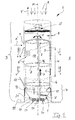
- Fig. 1 is a generally designated 1 device for cleaning with an arrow A illustrated and pollutant-containing exhaust air shown.
- These polluting exhaust air A arises in particular in agricultural plants, in those due to animals, feed materials, excrements o. The like.
- Filter container known in which a permeable by the exhaust air A filter material in the form of granules o. The like. Contained.
- In this granulate filter material Are harmful gas parts by microorganisms, chemical bond o. The like. Included and then by a continuous cleaning of the filter material the Erased noxious gas parts in the form of disposable as a biomass waste material.
- the device 1 is in accordance with the invention as a portable treatment plant B trained.
- this treatment plant B the exhaust air A is immediate at the point of origin in a filter material 3 can be introduced, so that in the exhaust air A contained noxious gas parts are bound in the filter material 3.
- the filter material 3 is fed to a continuous cleaning and from the system B, the purified fresh air according to arrow F directly into the Environment 2 be carried out.
- the filter material 3 is in a height H having a filter zone within the device 1 distributed and for filtering out the bound by the harmful gas contaminated components of the filter material 3, this is within the treatment plant B conveyed in a cycle including a flushing cleaning 4, so that by a continuous movement of the filter material 3 whose simple Reuse within the compact unit B is achieved.
- the Components of this assembly B are in the range of essential functional assemblies made of stainless steel.
- the treatment plant B has as a filter container on a double-wall assembly, from a tubular outer wall part 5 and an inside to this out a vertical passage space 6 for the filter material 3 defining inner wall part 7 is formed.
- Fig. 1 the components of this treatment plant B in a schematic representation illustrated in the respective items partially cut and see transparent in their installation position.
- harmful gas exhaust air is over an at least partially gas-permeable wall structure 8 (in Fig. 1 fragmentary indicated in the region of the left container part) in the filter zone H and the passage space 6, wherein this wall structure 8, the outer wall part. 5 and / or the inner wall part 7 permeable so limited that the filter zone H of the Passage chamber 6 optionally from different directions of flow for the air flow is accessible.
- this wall structure 8 the outer wall part. 5 and / or the inner wall part 7 permeable so limited that the filter zone H of the Passage chamber 6 optionally from different directions of flow for the air flow is accessible.
- the outer wall part 5 and the inner wall part 7 engage almost over the entire height of the treatment plant B according to the tube-in-tube principle into each other, these two parts with their radial distance D a Passage passage for the passage chamber 6 pretend.
- the two wall parts 5 and 7 are as an assembly concentric to a vertical vertical axis M of the device 1 arranged.
- the passage chamber 6 defines in a partial area H its up to the area of the lower Spülcuri 4 reaching total height the actual filter zone. It is also conceivable that provided for the filter zone H. permeable wall structures 8 detect a smaller area or the exhaust air A is pressed into the passage chamber 6 in the vertical direction and laterally is discharged (not shown).
- the filter material 3 in the passage space 6 arranged so that a vertical stratification in the form of one of the Wall parts 5 and 7 limited hollow cylinder (Fig. 2) is formed.
- this hollow cylinder Z the exhaust air A is introduced centrally, while the radially stratified filter material 3 substantially perpendicular to the cylinder axis (corresponds to vertical axis M) flows through the exhaust air A.
- the radially stratified filter material 3 substantially perpendicular to the cylinder axis (corresponds to vertical axis M) flows through the exhaust air A.
- the treatment plant B has an advantageously high efficiency.
- the two wall parts 5 and 7 are opposite provided with the respective gas-permeable wall structure 8, wherein these in Shape of a corresponding pore, sieve and / or hole structure, the gas permeability guaranteed.
- Particularly advantageous is the use of wood granules proved as a filter material 3, in particular hardwood, Bongosiholz o. Like. Nature products are used as starting material and thus an efficient Binding of dust and odor-intensive gas parts is detectable.
- the Application of treatment plant B is not based on the use of natural granules limited, but can also filter materials 3 made of plastic granules o. The like. Be used, so that in particular ammonia o. The like. Intensely smelling and irritating gases are bound in the filter material 3.
- the treatment plant B shown in FIG. 1 is constructed with assemblies that are in the installation position shown a substantially annular contour of the passage cross-section Define D. It is also conceivable that the outer wall part. 5 and / or the inner wall part 7 has a polygonal cross-sectional contour (not shown).
- the hollow cylindrical Stratifying filter material 3 during its movement in the passage space 6 out so that when moving in the direction of flow E, for example Ensured by the pollutant content of the supplied air A dependent residence time is.
- the filter material 3 is doing with a controlled lowering speed in the lower cleaning device 9 initiated.
- This optimization is done in particular from the aspect that the granular filter material 3 according to its respective Consistency, in particular the weight, the grain size and / or the Bulk density, may require a variable passage space 6, whose constructive adaptation with little effort is possible so that the application different filter materials 3 in the treatment plant B is guaranteed.
- the harmful gas-containing exhaust air A via a feed channel 10 formed by the interior of the inner wall part 7 introduced centrally into the treatment plant B, including a switchable fan G is provided.
- the sucked exhaust air A is on the filter zone H radially out of the Feeding channel 10 squeezed so that the cleaned exhaust air as clean air F in the immediate Environment 2 is distributable.
- the passage space 6 At its lower end is the passage space 6 with a regulating device 11, with which the supply (conveying direction E) of the contaminated in this area filter material 3 in the cleaning device 9 throttle or is releasable.
- Conceivable is a not shown Ring assembly, a spring-elastic cuff o.
- a generally designated 15 distribution unit at the end of a conveyor pipe sixteenth provided so that the filter material 3 'in the direction of arrow C above the passage space 6 experiences a largely uniform and horizontal distribution and the achieved annular distribution at the top of the hollow cylinder layer becomes.
- respective distributor rails are 17 (Fig. 2), a filter material 3 'distributing baffle plate (not shown) o. The like.
- the whole Distribution unit 15 may also be pivotable in a direction of rotation K, so that the filter material 3 'is optimally distributed.
- the bottom-side cleaning device 9 of the treatment plant B has a Collecting container 18, at the bottom one granules in the form of a water-filter material mixture circulating compressed air system 20 is connected. For emptying the bottom side supported at 19 treatment plant B is a corresponding discharge device 21 is provided.
Landscapes
- Chemical & Material Sciences (AREA)
- Chemical Kinetics & Catalysis (AREA)
- Dispersion Chemistry (AREA)
- Engineering & Computer Science (AREA)
- Analytical Chemistry (AREA)
- General Chemical & Material Sciences (AREA)
- Oil, Petroleum & Natural Gas (AREA)
- Filtering Of Dispersed Particles In Gases (AREA)
- Treating Waste Gases (AREA)
- Catching Or Destruction (AREA)
- Exhaust Gas After Treatment (AREA)
- Control Of Throttle Valves Provided In The Intake System Or In The Exhaust System (AREA)
Abstract
Description
- Fig. 1
- eine Prinzipdarstellung der Behandlungsanlage in vertikaler Gebrauchsstellung, und
- Fig. 2
- eine Draufsicht der Behandlungsanlage mit oberseitig in dieser vorgesehenen Verteilbaugruppen für das gereinigte Filtermaterial.
Claims (19)
- Vorrichtung zum Reinigen von Schadgase enthaltender Abluft (A), insbesondere aus landwirtschaftlichen Anlagen, mit einem ein von der Abluft (A) durchströmbares Filtermaterial (3) in Form von Granulat o. dgl. aufnehmenden Filterbehälter, wobei zur Entfernung von ausgefilterten Schadgas-Teilen eine Spülreinigung (4) des Filtermaterials (3) vorgesehen ist, dadurch gekennzeichnet, daß die Vorrichtung (1) als eine transportable Behandlungsanlage (B) ausgebildet ist, wobei die Abluft (A; A') unmittelbar am Entstehungsort in das Filtermaterial (3) einleitbar, das Schadgas-Teile bindende Filtermaterial (3) einer kontinuierlichen Reinigung innerhalb der Behandlungsanlage (B) zuführbar und aus dieser die gereinigte Frischluft (F; F') direkt in die Umgebung (2) ausförderbar ist.
- Vorrichtung nach Anspruch 1, dadurch gekennzeichnet, daß das Filtermaterial (3) in einer Filterzone (H) verteilbar und innerhalb der Behandlungsanlage (B) in einem die Spülreinigung (4) einschließenden Kreislauf kontinuierlich förderbar ist.
- Vorrichtung nach Anspruch 1 oder 2, dadurch gekennzeichnet, daß der Filterbehälter der Behandlungsanlage (B) aus einem rohrförmigen Außenwandteil (5) und einem innenseitig zu diesem hin einen vertikalen Durchlaßraum (6) für das Filtermaterial (3) definierenden Innenwandteil (7) gebildet ist.
- Vorrichtung nach einem der Ansprüche 1 bis 3, dadurch gekennzeichnet, daß die schadgashaltige Abluft (A; A') über eine zumindest bereichsweise gasdurchlässige Wandungsstruktur (8) des Außenwandteils (5) und/oder des Innenwandteils (7) durch die Filterzone (H) des Durchlaßraumes (6) leitbar ist.
- Vorrichtung nach einem der Ansprüche 1 bis 4, dadurch gekennzeichnet, daß die Strömungsrichtung der in den Durchlaßraum (6) bzw. die Filterzone (H) eingeleiteten Abluft (A; A') umschaltbar ist.
- Vorrichtung nach einem der Ansprüche 1 bis 5, dadurch gekennzeichnet, daß das Außenwandteil (5) und das Innenwandteil (7) als jeweilige nach dem Rohr-in-Rohr-Prinzip ineinandergreifende, mit ihrem radialen Abstand einen Durchlaßquerschnitt des Durchlaßraumes (6) vorgebende und konzentrisch zu einer vertikalen Hochachse (M) angeordnete Baugruppen ausgebildet sind.
- Vorrichtung nach einem der Ansprüche 1 bis 6, dadurch gekennzeichnet, daß der Durchlaßraum (6) in einem Teilbereich seiner Höhe die Filterzone (H) definiert.
- Vorrichtung nach einem der Ansprüche 1 bis 7, dadurch gekennzeichnet, daß im Durchlaßraum (6) das Filtermaterial (3) eine vertikale Schichtung in Form eines von den Wandteilen (5, 7) begrenzten Hohlzylinders (Z) bildet, in diesen die Abluft (A; A') einleitbar und die Hohlzylinder-Schicht im wesentlichen senkrecht zu ihrer vertikalen Zylinderachse (M) von der Abluft (A; A') durchströmbar ist.
- Vorrichtung nach einem der Ansprüche 1 bis 8, dadurch gekennzeichnet, daß das gereinigte Filtermaterial (3') oberseitig im Durchlaßraum (6) horizontal verteilt zuführbar, das Filtermaterial (3) unter Schwerkraftwirkung (Pfeil E) vertikal im Durchlaßraum (6) verlagerbar, unterseitig aus diesem das Filtermaterial (3) mit dem am Granulat gebundenen Schadgas entnehmbar und dieses in einer Reinigungsvorrichtung (9) ausspülbar ist.
- Vorrichtung nach einem der Ansprüche 1 bis 9, dadurch gekennzeichnet, daß der Innenwandteil (7) und der Außenwandteil (5) den Durchlaßraum (6) jeweils mit einer der zumindest bereichsweise gasdurchlässigen Wandungsstrukturen (8) begrenzen und diese beiden Wandungsstrukturen (8) gegenüberliegend angeordnet sind.
- Vorrichtung nach Anspruch 10, dadurch gekennzeichnet, daß die Wandungen (5, 7) mittels einer Poren-, Sieb- und/oder Lochstruktur gasdurchlässig sind.
- Vorrichtung nach einem der Ansprüche 1 bis 11, dadurch gekennzeichnet, daß das Außenwandteil (5) und das Innenwandteil (7) eine zylindrische oder vieleckige Querschnittskontur aufweisen und in Einbaulage die im wesentlichen ringförmige Kontur des Durchlaßquerschnitts (D) definieren.
- Vorrichtung nach einem der Ansprüche 1 bis 12, dadurch gekennzeichnet, daß der Durchlaßraum (6) das die hohlzylinderförmige Schichtung (Z) bildende Filtermaterial (3) in einer vom Schadstoffgehalt der zugeführten Abluft (A; A') abhängenden Verweilzeit aufnimmt und das Filtermaterial (3) mit gesteuerter Absenkgeschwindigkeit in die untere Reinigungsvorrichtung (9) einleitbar ist.
- Vorrichtung nach einem der Ansprüche 1 bis 13, dadurch gekennzeichnet, daß der Durchlaßraum (6) in seinem Querschnittsmaß (D) entsprechend dem Gewicht, der Korngröße und/oder der Schüttdichte des Granulat-Filtermaterials (3) variabel ausführbar ist.
- Vorrichtung nach einem der Ansprüche 1 bis 14, dadurch gekennzeichnet, daß die schadgashaltige Abluft (A; A') über einen vom Innenraum des Innenwandteils (7) gebildeten Zuführkanal (10) zentral in die Behandlungsanlage (B) einführbar, über die Filterzone (H) radial auspreßbar und als Reinluft (F; F') in der unmittelbaren Umgebung (2) verteilbar ist.
- Vorrichtung nach einem der Ansprüche 1 bis 15, dadurch gekennzeichnet, daß der Durchlaßraum (6) an seinem unteren Ende mit einer Regulierungsvorrichtung (11) versehen ist, mit der die Zufuhr des verunreinigten Filtermaterials (3) in die Reinigungsvorrichtung (9) drossel- bzw. freigebbar ist.
- Vorrichtung nach einem der Ansprüche 1 bis 16, dadurch gekennzeichnet, daß diese im Bereich der Regulierungsvorrichtung (11) mit einer in den unteren Bereich der Filterzone (H) eingreifenden Schadstoffmeßsonde (12) und/oder einem Füllstandsregler (13) im Bereich der Reinigungsvorrichtung (9) zusammenwirkt.
- Vorrichtung nach einem der Ansprüche 1 bis 17, dadurch gekennzeichnet, daß das gereinigte Filtermaterial (3') mittels einer Pumpe (14) zentral im Zuführkanal (10) in der Behandlungsanlage (B) hochförderbar und mittels einer Verteileinheit (15) oberhalb des Durchlaßraumes (6) horizontal gleichmäßig verteilt in den kreisringförmigen Bereich der Hohlzylinder-Schicht (Z) zuführbar ist.
- Vorrichtung nach einem der Ansprüche 1 bis 18, dadurch gekennzeichnet, daß die Reinigungsvorrichtung (9) einen Sammelbehälter (18) aufweist, an den bodenund/oder wandungsseitig eine das Wasser-Filtermaterial-Gemisch umwälzende und eine Sauerstoffanreicherung bewirkende Druckluftanlage (20) angeschlossen ist.
Applications Claiming Priority (2)
| Application Number | Priority Date | Filing Date | Title |
|---|---|---|---|
| DE20313713U | 2003-09-04 | ||
| DE20313713U DE20313713U1 (de) | 2003-09-04 | 2003-09-04 | Vorrichtung zum Reinigen von Abluft aus landwirtschaftlichen Anlagen |
Publications (2)
| Publication Number | Publication Date |
|---|---|
| EP1512454A1 true EP1512454A1 (de) | 2005-03-09 |
| EP1512454B1 EP1512454B1 (de) | 2009-01-07 |
Family
ID=32946552
Family Applications (1)
| Application Number | Title | Priority Date | Filing Date |
|---|---|---|---|
| EP04020984A Expired - Lifetime EP1512454B1 (de) | 2003-09-04 | 2004-09-03 | Vorrichtung zum Reinigen von Abluft aus landwirtschaftlichen Anlagen |
Country Status (4)
| Country | Link |
|---|---|
| EP (1) | EP1512454B1 (de) |
| AT (1) | ATE419914T1 (de) |
| DE (2) | DE20313713U1 (de) |
| DK (1) | DK1512454T3 (de) |
Cited By (1)
| Publication number | Priority date | Publication date | Assignee | Title |
|---|---|---|---|---|
| CN112755700A (zh) * | 2020-12-15 | 2021-05-07 | 瞿松华 | 一种用于空气净化的有害颗粒物处理用净化装置 |
Families Citing this family (1)
| Publication number | Priority date | Publication date | Assignee | Title |
|---|---|---|---|---|
| WO2017103023A1 (en) * | 2015-12-17 | 2017-06-22 | Solvay Sa | Gas extraction method using adsorbent particles, adsorber and gas extraction system |
Citations (7)
| Publication number | Priority date | Publication date | Assignee | Title |
|---|---|---|---|---|
| DE825393C (de) * | 1948-10-02 | 1951-12-17 | Metallgesellschaft Ag | Verfahren zur Abtrennung von Stoffen aus Gasen mittels Adsorptionsmitteln |
| DE2256963A1 (de) * | 1972-11-21 | 1974-05-22 | Babcock & Wilcox Ag | Silo zur reinigung von rauchgasen |
| US4255403A (en) * | 1979-07-31 | 1981-03-10 | Exxon Research And Engineering Co. | Magnetically stabilized fluid cross-flow contactor having support means and process for using the same |
| EP0095999A1 (de) * | 1982-05-13 | 1983-12-07 | Hans H. Dr. Stiehl | Verfahren und Vorrichtung zum kontinuierlichen Austausch von in einem chemischen und/oder physikalischen Vorgang, wie z.B. einem Filter-, einem Adsorptions- oder Trockenvorgang, verbrauchten regenerierbaren Kontaktmitteln, wie Filtermaterialien, Trockenmitteln, Adsorbermaterialien oder Katalysatoren |
| DE3331225A1 (de) * | 1983-08-30 | 1985-03-14 | Energie Systemplanung Insumma GmbH, 8500 Nürnberg | Filtervorrichtung zur abgasfilterung |
| WO1994008697A1 (en) * | 1992-10-22 | 1994-04-28 | Senea Miljöteknik Ab | Method for flue-gas cleaning |
| DE19961691A1 (de) * | 1999-12-20 | 2001-06-21 | Bifa Gmbh Bayerisches Inst Fue | Verfahren und Vorrichtung zur Reinigung von Rauchgas |
Family Cites Families (3)
| Publication number | Priority date | Publication date | Assignee | Title |
|---|---|---|---|---|
| DE3311108A1 (de) * | 1983-03-26 | 1984-09-27 | Klöckner-Humboldt-Deutz AG, 5000 Köln | Filter zur reinigung von gasen |
| DE8407661U1 (de) * | 1984-03-13 | 1987-11-12 | Helsa-Werke Helmut Sandler GmbH & Co KG, 8586 Gefrees | Filtervorrichtung mit Adsorbermaterial in Granulatform |
| DE3636467A1 (de) * | 1986-10-25 | 1988-04-28 | Kloeckner Humboldt Deutz Ag | Filter zur reinigung von gasen |
-
2003
- 2003-09-04 DE DE20313713U patent/DE20313713U1/de not_active Expired - Lifetime
-
2004
- 2004-09-03 AT AT04020984T patent/ATE419914T1/de not_active IP Right Cessation
- 2004-09-03 DE DE502004008808T patent/DE502004008808D1/de not_active Expired - Lifetime
- 2004-09-03 EP EP04020984A patent/EP1512454B1/de not_active Expired - Lifetime
- 2004-09-03 DK DK04020984T patent/DK1512454T3/da active
Patent Citations (7)
| Publication number | Priority date | Publication date | Assignee | Title |
|---|---|---|---|---|
| DE825393C (de) * | 1948-10-02 | 1951-12-17 | Metallgesellschaft Ag | Verfahren zur Abtrennung von Stoffen aus Gasen mittels Adsorptionsmitteln |
| DE2256963A1 (de) * | 1972-11-21 | 1974-05-22 | Babcock & Wilcox Ag | Silo zur reinigung von rauchgasen |
| US4255403A (en) * | 1979-07-31 | 1981-03-10 | Exxon Research And Engineering Co. | Magnetically stabilized fluid cross-flow contactor having support means and process for using the same |
| EP0095999A1 (de) * | 1982-05-13 | 1983-12-07 | Hans H. Dr. Stiehl | Verfahren und Vorrichtung zum kontinuierlichen Austausch von in einem chemischen und/oder physikalischen Vorgang, wie z.B. einem Filter-, einem Adsorptions- oder Trockenvorgang, verbrauchten regenerierbaren Kontaktmitteln, wie Filtermaterialien, Trockenmitteln, Adsorbermaterialien oder Katalysatoren |
| DE3331225A1 (de) * | 1983-08-30 | 1985-03-14 | Energie Systemplanung Insumma GmbH, 8500 Nürnberg | Filtervorrichtung zur abgasfilterung |
| WO1994008697A1 (en) * | 1992-10-22 | 1994-04-28 | Senea Miljöteknik Ab | Method for flue-gas cleaning |
| DE19961691A1 (de) * | 1999-12-20 | 2001-06-21 | Bifa Gmbh Bayerisches Inst Fue | Verfahren und Vorrichtung zur Reinigung von Rauchgas |
Cited By (1)
| Publication number | Priority date | Publication date | Assignee | Title |
|---|---|---|---|---|
| CN112755700A (zh) * | 2020-12-15 | 2021-05-07 | 瞿松华 | 一种用于空气净化的有害颗粒物处理用净化装置 |
Also Published As
| Publication number | Publication date |
|---|---|
| DE20313713U1 (de) | 2004-09-02 |
| EP1512454B1 (de) | 2009-01-07 |
| DE502004008808D1 (de) | 2009-02-26 |
| DK1512454T3 (da) | 2009-05-11 |
| ATE419914T1 (de) | 2009-01-15 |
Similar Documents
| Publication | Publication Date | Title |
|---|---|---|
| EP0243358B1 (de) | Verfahren und vorrichtung zum reinigen lösungsmittelbelasteter abluft | |
| DE102006027882B4 (de) | Wäscher zum Behandeln von Halbleiter-Abgas | |
| DE2558256A1 (de) | Filtereinrichtung zum abscheiden gasfoermiger organischer verunreinigungen aus abgasen | |
| EP0210196A1 (de) | Verfahren und vorrichtung zum trocknen und konditionieren von hühnermist oder ähnlichen pastösen stoffen. | |
| CN110591896A (zh) | 区域内粪便无害化封闭处理设备及工艺 | |
| CN208327752U (zh) | 一种污水净化处理系统 | |
| EP0530672B1 (de) | Auswaschbarer Filter | |
| CN2165916Y (zh) | 污浊气体过滤装置 | |
| DE19623229A1 (de) | Betriebsvorrichtungen und -verfahren für eine wartungsfreie Warmwasser-Aquarienanlage | |
| EP1512454B1 (de) | Vorrichtung zum Reinigen von Abluft aus landwirtschaftlichen Anlagen | |
| DE102005000768A1 (de) | Vorrichtung und Verfahren zur Erzeugung von Pyrolysegas | |
| CN206390030U (zh) | 一种智能循环水养殖系统 | |
| DE102009055182B4 (de) | Verrieselungsstrippmodul und Verfahren zur Entfernung flüchtiger gelöster Stoffe aus Grundwasserströmen durch anoxisches Vakuumstrippen | |
| EP3015157B1 (de) | Filter und filtersystem | |
| DE3443832C2 (de) | Schüttschichtfilter, insbesondere für Rauchgase | |
| EP0048683B1 (de) | Verfahren und Vorrichtung zur Reinigung von Schmutzrückständen | |
| DE19603959C1 (de) | Verfahren und Vorrichtung zum Behandeln von biologisch belastetem Abwasser, insbesondere von Haushaltsabwasser | |
| CN112358094B (zh) | 一种养鸡用废水处理设备 | |
| DE19961691B4 (de) | Verfahren zur Reinigung von Rauchgas | |
| CN111111288B (zh) | 一种模块化污水处理系统 | |
| EP0856345A1 (de) | Anordnung zur Entfernung von Gasen aus Grund- und/oder Abwasser | |
| DE102007049845A1 (de) | Filteranlage zum Entfernen von partikulären und oder gelösten Teilchen aus insbesondere stehenden Gewässern | |
| DE102007059549A1 (de) | Luft - Waschanlage (Feinstaubwaschanlage) für Feinstoffe, Feststoffe, Pollen etc. | |
| CN113620530A (zh) | 一种黑臭水体生态净化处理系统 | |
| DE202008002100U1 (de) | Vorrichtung zum mechanischen Filtern und zur biologischen Aufbereitung von organisch belastetem Teichwasser |
Legal Events
| Date | Code | Title | Description |
|---|---|---|---|
| PUAI | Public reference made under article 153(3) epc to a published international application that has entered the european phase |
Free format text: ORIGINAL CODE: 0009012 |
|
| AK | Designated contracting states |
Kind code of ref document: A1 Designated state(s): AT BE BG CH CY CZ DE DK EE ES FI FR GB GR HU IE IT LI LU MC NL PL PT RO SE SI SK TR |
|
| AX | Request for extension of the european patent |
Extension state: AL HR LT LV MK |
|
| 17P | Request for examination filed |
Effective date: 20050901 |
|
| AKX | Designation fees paid |
Designated state(s): AT BE BG CH CY CZ DE DK EE ES FI FR GB GR HU IE IT LI LU MC NL PL PT RO SE SI SK TR |
|
| 17Q | First examination report despatched |
Effective date: 20071106 |
|
| GRAP | Despatch of communication of intention to grant a patent |
Free format text: ORIGINAL CODE: EPIDOSNIGR1 |
|
| GRAS | Grant fee paid |
Free format text: ORIGINAL CODE: EPIDOSNIGR3 |
|
| GRAA | (expected) grant |
Free format text: ORIGINAL CODE: 0009210 |
|
| AK | Designated contracting states |
Kind code of ref document: B1 Designated state(s): AT BE BG CH CY CZ DE DK EE ES FI FR GB GR HU IE IT LI LU MC NL PL PT RO SE SI SK TR |
|
| REG | Reference to a national code |
Ref country code: GB Ref legal event code: FG4D Free format text: NOT ENGLISH |
|
| REG | Reference to a national code |
Ref country code: CH Ref legal event code: EP |
|
| REG | Reference to a national code |
Ref country code: IE Ref legal event code: FG4D Free format text: LANGUAGE OF EP DOCUMENT: GERMAN |
|
| REF | Corresponds to: |
Ref document number: 502004008808 Country of ref document: DE Date of ref document: 20090226 Kind code of ref document: P |
|
| REG | Reference to a national code |
Ref country code: DK Ref legal event code: T3 |
|
| PG25 | Lapsed in a contracting state [announced via postgrant information from national office to epo] |
Ref country code: SI Free format text: LAPSE BECAUSE OF FAILURE TO SUBMIT A TRANSLATION OF THE DESCRIPTION OR TO PAY THE FEE WITHIN THE PRESCRIBED TIME-LIMIT Effective date: 20090107 |
|
| PG25 | Lapsed in a contracting state [announced via postgrant information from national office to epo] |
Ref country code: FI Free format text: LAPSE BECAUSE OF FAILURE TO SUBMIT A TRANSLATION OF THE DESCRIPTION OR TO PAY THE FEE WITHIN THE PRESCRIBED TIME-LIMIT Effective date: 20090107 Ref country code: ES Free format text: LAPSE BECAUSE OF FAILURE TO SUBMIT A TRANSLATION OF THE DESCRIPTION OR TO PAY THE FEE WITHIN THE PRESCRIBED TIME-LIMIT Effective date: 20090418 |
|
| REG | Reference to a national code |
Ref country code: IE Ref legal event code: FD4D |
|
| PG25 | Lapsed in a contracting state [announced via postgrant information from national office to epo] |
Ref country code: SE Free format text: LAPSE BECAUSE OF FAILURE TO SUBMIT A TRANSLATION OF THE DESCRIPTION OR TO PAY THE FEE WITHIN THE PRESCRIBED TIME-LIMIT Effective date: 20090407 Ref country code: PT Free format text: LAPSE BECAUSE OF FAILURE TO SUBMIT A TRANSLATION OF THE DESCRIPTION OR TO PAY THE FEE WITHIN THE PRESCRIBED TIME-LIMIT Effective date: 20090608 Ref country code: PL Free format text: LAPSE BECAUSE OF FAILURE TO SUBMIT A TRANSLATION OF THE DESCRIPTION OR TO PAY THE FEE WITHIN THE PRESCRIBED TIME-LIMIT Effective date: 20090107 |
|
| PG25 | Lapsed in a contracting state [announced via postgrant information from national office to epo] |
Ref country code: IE Free format text: LAPSE BECAUSE OF FAILURE TO SUBMIT A TRANSLATION OF THE DESCRIPTION OR TO PAY THE FEE WITHIN THE PRESCRIBED TIME-LIMIT Effective date: 20090107 Ref country code: EE Free format text: LAPSE BECAUSE OF FAILURE TO SUBMIT A TRANSLATION OF THE DESCRIPTION OR TO PAY THE FEE WITHIN THE PRESCRIBED TIME-LIMIT Effective date: 20090107 Ref country code: CZ Free format text: LAPSE BECAUSE OF FAILURE TO SUBMIT A TRANSLATION OF THE DESCRIPTION OR TO PAY THE FEE WITHIN THE PRESCRIBED TIME-LIMIT Effective date: 20090107 |
|
| PLBE | No opposition filed within time limit |
Free format text: ORIGINAL CODE: 0009261 |
|
| STAA | Information on the status of an ep patent application or granted ep patent |
Free format text: STATUS: NO OPPOSITION FILED WITHIN TIME LIMIT |
|
| PG25 | Lapsed in a contracting state [announced via postgrant information from national office to epo] |
Ref country code: RO Free format text: LAPSE BECAUSE OF FAILURE TO SUBMIT A TRANSLATION OF THE DESCRIPTION OR TO PAY THE FEE WITHIN THE PRESCRIBED TIME-LIMIT Effective date: 20090107 Ref country code: SK Free format text: LAPSE BECAUSE OF FAILURE TO SUBMIT A TRANSLATION OF THE DESCRIPTION OR TO PAY THE FEE WITHIN THE PRESCRIBED TIME-LIMIT Effective date: 20090107 |
|
| 26N | No opposition filed |
Effective date: 20091008 |
|
| PG25 | Lapsed in a contracting state [announced via postgrant information from national office to epo] |
Ref country code: BG Free format text: LAPSE BECAUSE OF FAILURE TO SUBMIT A TRANSLATION OF THE DESCRIPTION OR TO PAY THE FEE WITHIN THE PRESCRIBED TIME-LIMIT Effective date: 20090407 |
|
| BERE | Be: lapsed |
Owner name: LAMMERS SYSTEMTECHNIK G.M.B.H. & CO. KG Effective date: 20090930 |
|
| PG25 | Lapsed in a contracting state [announced via postgrant information from national office to epo] |
Ref country code: MC Free format text: LAPSE BECAUSE OF NON-PAYMENT OF DUE FEES Effective date: 20090930 |
|
| REG | Reference to a national code |
Ref country code: CH Ref legal event code: PL |
|
| REG | Reference to a national code |
Ref country code: DK Ref legal event code: EBP |
|
| GBPC | Gb: european patent ceased through non-payment of renewal fee |
Effective date: 20090903 |
|
| REG | Reference to a national code |
Ref country code: FR Ref legal event code: ST Effective date: 20100531 |
|
| PG25 | Lapsed in a contracting state [announced via postgrant information from national office to epo] |
Ref country code: FR Free format text: LAPSE BECAUSE OF NON-PAYMENT OF DUE FEES Effective date: 20090930 |
|
| PG25 | Lapsed in a contracting state [announced via postgrant information from national office to epo] |
Ref country code: BE Free format text: LAPSE BECAUSE OF NON-PAYMENT OF DUE FEES Effective date: 20090930 |
|
| PG25 | Lapsed in a contracting state [announced via postgrant information from national office to epo] |
Ref country code: GR Free format text: LAPSE BECAUSE OF FAILURE TO SUBMIT A TRANSLATION OF THE DESCRIPTION OR TO PAY THE FEE WITHIN THE PRESCRIBED TIME-LIMIT Effective date: 20090408 Ref country code: CH Free format text: LAPSE BECAUSE OF NON-PAYMENT OF DUE FEES Effective date: 20090930 Ref country code: LI Free format text: LAPSE BECAUSE OF NON-PAYMENT OF DUE FEES Effective date: 20090930 |
|
| PG25 | Lapsed in a contracting state [announced via postgrant information from national office to epo] |
Ref country code: AT Free format text: LAPSE BECAUSE OF NON-PAYMENT OF DUE FEES Effective date: 20090903 Ref country code: GB Free format text: LAPSE BECAUSE OF NON-PAYMENT OF DUE FEES Effective date: 20090903 |
|
| PG25 | Lapsed in a contracting state [announced via postgrant information from national office to epo] |
Ref country code: DK Free format text: LAPSE BECAUSE OF NON-PAYMENT OF DUE FEES Effective date: 20090930 |
|
| PGFP | Annual fee paid to national office [announced via postgrant information from national office to epo] |
Ref country code: NL Payment date: 20100929 Year of fee payment: 7 |
|
| PG25 | Lapsed in a contracting state [announced via postgrant information from national office to epo] |
Ref country code: IT Free format text: LAPSE BECAUSE OF FAILURE TO SUBMIT A TRANSLATION OF THE DESCRIPTION OR TO PAY THE FEE WITHIN THE PRESCRIBED TIME-LIMIT Effective date: 20090107 |
|
| PG25 | Lapsed in a contracting state [announced via postgrant information from national office to epo] |
Ref country code: LU Free format text: LAPSE BECAUSE OF NON-PAYMENT OF DUE FEES Effective date: 20090903 |
|
| PG25 | Lapsed in a contracting state [announced via postgrant information from national office to epo] |
Ref country code: HU Free format text: LAPSE BECAUSE OF FAILURE TO SUBMIT A TRANSLATION OF THE DESCRIPTION OR TO PAY THE FEE WITHIN THE PRESCRIBED TIME-LIMIT Effective date: 20090708 |
|
| PG25 | Lapsed in a contracting state [announced via postgrant information from national office to epo] |
Ref country code: TR Free format text: LAPSE BECAUSE OF FAILURE TO SUBMIT A TRANSLATION OF THE DESCRIPTION OR TO PAY THE FEE WITHIN THE PRESCRIBED TIME-LIMIT Effective date: 20090107 |
|
| PG25 | Lapsed in a contracting state [announced via postgrant information from national office to epo] |
Ref country code: CY Free format text: LAPSE BECAUSE OF FAILURE TO SUBMIT A TRANSLATION OF THE DESCRIPTION OR TO PAY THE FEE WITHIN THE PRESCRIBED TIME-LIMIT Effective date: 20090107 |
|
| REG | Reference to a national code |
Ref country code: NL Ref legal event code: V1 Effective date: 20120401 |
|
| PG25 | Lapsed in a contracting state [announced via postgrant information from national office to epo] |
Ref country code: NL Free format text: LAPSE BECAUSE OF NON-PAYMENT OF DUE FEES Effective date: 20120401 |
|
| PGFP | Annual fee paid to national office [announced via postgrant information from national office to epo] |
Ref country code: DE Payment date: 20121114 Year of fee payment: 9 |
|
| REG | Reference to a national code |
Ref country code: DE Ref legal event code: R119 Ref document number: 502004008808 Country of ref document: DE Effective date: 20140401 |
|
| PG25 | Lapsed in a contracting state [announced via postgrant information from national office to epo] |
Ref country code: DE Free format text: LAPSE BECAUSE OF NON-PAYMENT OF DUE FEES Effective date: 20140401 |