EP1512441A1 - Dispositif d'accueil d'un pied ou d'une chaussure sur un engin de sport - Google Patents
Dispositif d'accueil d'un pied ou d'une chaussure sur un engin de sport Download PDFInfo
- Publication number
- EP1512441A1 EP1512441A1 EP04020352A EP04020352A EP1512441A1 EP 1512441 A1 EP1512441 A1 EP 1512441A1 EP 04020352 A EP04020352 A EP 04020352A EP 04020352 A EP04020352 A EP 04020352A EP 1512441 A1 EP1512441 A1 EP 1512441A1
- Authority
- EP
- European Patent Office
- Prior art keywords
- rear support
- slider
- support element
- reception device
- wall
- Prior art date
- Legal status (The legal status is an assumption and is not a legal conclusion. Google has not performed a legal analysis and makes no representation as to the accuracy of the status listed.)
- Granted
Links
- 230000003100 immobilizing effect Effects 0.000 claims abstract description 11
- 230000002787 reinforcement Effects 0.000 claims description 21
- 230000000295 complement effect Effects 0.000 claims description 3
- 230000000670 limiting effect Effects 0.000 claims description 3
- 210000002683 foot Anatomy 0.000 description 6
- 230000002829 reductive effect Effects 0.000 description 3
- 210000003423 ankle Anatomy 0.000 description 2
- 239000000463 material Substances 0.000 description 2
- 230000036961 partial effect Effects 0.000 description 2
- 230000000717 retained effect Effects 0.000 description 2
- 230000002441 reversible effect Effects 0.000 description 2
- 238000003860 storage Methods 0.000 description 2
- 230000001464 adherent effect Effects 0.000 description 1
- 238000004026 adhesive bonding Methods 0.000 description 1
- 238000004140 cleaning Methods 0.000 description 1
- 238000004519 manufacturing process Methods 0.000 description 1
- 229910052751 metal Inorganic materials 0.000 description 1
- 239000002184 metal Substances 0.000 description 1
- 150000002739 metals Chemical class 0.000 description 1
- 210000000878 metatarsophalangeal joint Anatomy 0.000 description 1
- 238000000034 method Methods 0.000 description 1
- 230000035515 penetration Effects 0.000 description 1
- 229920003023 plastic Polymers 0.000 description 1
- 239000004033 plastic Substances 0.000 description 1
- 239000000843 powder Substances 0.000 description 1
- 229920002994 synthetic fiber Polymers 0.000 description 1
- XLYOFNOQVPJJNP-UHFFFAOYSA-N water Substances O XLYOFNOQVPJJNP-UHFFFAOYSA-N 0.000 description 1
- 238000003466 welding Methods 0.000 description 1
Images


Classifications
-
- A—HUMAN NECESSITIES
- A63—SPORTS; GAMES; AMUSEMENTS
- A63C—SKATES; SKIS; ROLLER SKATES; DESIGN OR LAYOUT OF COURTS, RINKS OR THE LIKE
- A63C10/00—Snowboard bindings
- A63C10/28—Snowboard bindings characterised by auxiliary devices or arrangements on the bindings
- A63C10/285—Pads as foot or binding supports, e.g. pads made of foam
-
- A—HUMAN NECESSITIES
- A63—SPORTS; GAMES; AMUSEMENTS
- A63C—SKATES; SKIS; ROLLER SKATES; DESIGN OR LAYOUT OF COURTS, RINKS OR THE LIKE
- A63C10/00—Snowboard bindings
- A63C10/02—Snowboard bindings characterised by details of the shoe holders
- A63C10/04—Shoe holders for passing over the shoe
-
- A—HUMAN NECESSITIES
- A63—SPORTS; GAMES; AMUSEMENTS
- A63C—SKATES; SKIS; ROLLER SKATES; DESIGN OR LAYOUT OF COURTS, RINKS OR THE LIKE
- A63C10/00—Snowboard bindings
- A63C10/02—Snowboard bindings characterised by details of the shoe holders
- A63C10/04—Shoe holders for passing over the shoe
- A63C10/06—Straps therefor, e.g. adjustable straps
-
- A—HUMAN NECESSITIES
- A63—SPORTS; GAMES; AMUSEMENTS
- A63C—SKATES; SKIS; ROLLER SKATES; DESIGN OR LAYOUT OF COURTS, RINKS OR THE LIKE
- A63C10/00—Snowboard bindings
- A63C10/24—Calf or heel supports, e.g. adjustable high back or heel loops
Definitions
- the invention relates to a device for receiving a foot or a shoe on a machine sport.
- Such devices are used for snowboarding or snowboarding, skiing on snow or on water, snowshoe, rollerblading, or whatever.
- Some devices according to the prior art comprise a seat, intended to accommodate the foot sole or sole of the footwear and a rear support element intended for support the lower leg of a user.
- the rear support element has a support surface opposed to a free face, the support face receiving the lower leg.
- the seat is associated with the rear support element as follows. First of all the seat extends in length from a rear end to a front end.
- the rear support element meanwhile has an attachment end opposite to a free end, an axis joint substantially transverse connecting the attachment end to the seat.
- the rear support element is therefore rotatably mounted relative to the seat. The joint makes it possible to reduce the bulk of the device for its storage, by tilting the rear support element forward.
- a stop is provided to limit a rotation towards the rear of the rear support element.
- the stop is adjustable, to adapt the device to the user.
- the stop includes a movable cursor along the rear support element, as well as a means for immobilizing the slider on the back support element. It suffices to act on the means of immobilization for ability to adjust the position of the cursor, and therefore the angular position of the support element back to the seat.
- the cursor and the immobilizing means are located on the side of the free face of the rear support element, so that the cursor position can be adjusted as well when the shoe is in or out of the device. An adjustment is possible because the immobilization means is directly accessible. This is a characteristic of use of the device.
- snowboarding snow or ice can be an obstacle to moving or stopping the cursor.
- the latter generally has teeth intended to cooperate with a toothing of the rear support element. If snow or ice is fits in the teeth, moving the cursor becomes difficult or impossible in some extreme cases. It is the same for immobilization because the taking of teeth is not done, or at least not correctly. The user must therefore clean his device, which is often long and impractical.
- the purpose of the invention is notably to facilitate the movement of the cursor along the rear support element, or its immobilization.
- the invention proposes a device for receiving a foot or a shoe on a sports vehicle, the device comprising a seat associated with a rear support element, the rear support element having a bearing surface opposite to a free face, the element rear support being rotatably mounted relative to the seat, an abutment limiting a rotation towards the rear of the rear support member, the stop comprising a movable cursor along the rear support element and a means for immobilizing the cursor on the support element back.
- the reception device is characterized in that a wall covers the cursor on the side of the free face, the immobilizing means passing through the wall.
- the wall strongly or even totally limits the arrival of foreign bodies at the level of cursor. Simultaneously the immobilization means remains accessible to the user. So the inclination of the rear support element can be easily done. The absence of foreign bodies avoid cleaning. An advantage that results is the time saved. Another advantage is the comfort of use of the device, as regards the inclination adjustment of the element rear support.
- a reception device 1 allows reception temporary on a board 2 of a shoe not shown.
- the reception device 1 comprises a seat 3 which extends in length between a rear end 4 and a front end 5, and in width from a first edge 6 to a second edge 7.
- the seat 3 has an upper face 8 provided to be facing the sole of the shoe, and a lower face 9 provided to be above the board 2.
- the seat 3 preferably comprises a base 10 covered with a cushion 11.
- the base 10 is a rigid piece which delimits at least partly the lower face 9.
- the cushion 11 as to at least partially delimits the upper face 8.
- the cushion 11 extends from the rear end 4 to the front end 5 of the seat 3. This allows a cushioned contact with the entire surface of the sole of the shoe.
- a rear portion 12 and a front portion 13 of the cushion 11 delimit a housing space 14 for the base 10.
- seat 3 may be provided, such as for example a base associated with two cushions, one at the back, the other at the front.
- the seat 3 is retained in the board 2 by means made in the form of a disc, itself retained in the board 2 by screws.
- the seat 3 is bordered laterally by a first portion represented in the form of a first flange 20, as well as by a second part represented in the form of a second flange 21.
- first flange 20 is lateral and the second 21 is medial, but it could have been the opposite.
- the flanges 20, 21 delimit a reception area 22 of the shoe. When the latter is in place on the device 1, the flanges 20, 21 run along the sole laterally. Of course, something other than flanges 20, 21 to form the lateral and medial portions. For example stops could suit.
- the base 10 and the flanges 20, 21 form a single piece made by example in synthetic material.
- the flanges 20, 21 are parts secured to the base by any means, such as gluing, welding, screwing, interlocking, or other.
- a first link 23 is located forward, at the level of the metatarsophalangeal joint when the foot is held.
- a second link 24 is located aft, at the level of the instep when the foot is held.
- Each of the links 23, 24 extends transversely between the flanges 20, 21.
- the first link 23 comprises for example a lateral portion 25 and a medial portion 26, which are respectively attached to the lateral and medial flanges 21.
- a device linkage 27 makes it possible to connect to one another, in a reversible manner, the lateral portions 25 and 26.
- the binding device 27 makes it possible to tighten the shoe according to an intensity desired.
- the second link 24 comprises for example a lateral portion 28 and a medial portion 29, which are respectively attached to the lateral flanges 20 and medial 21.
- a connecting device 30 allows to connect to one another, so reversible, the lateral portions 28 and medial 29.
- the connecting device 30 allows to tighten the shoe to a desired intensity.
- the second link 24 also comprises, according to the embodiment described, a division rear 31.
- the latter extends the second link 24 rearward, to bypass the heel, or the back of the user's ankle or lower leg.
- the association of lateral portions 28 and medial 29 form a division before 32 of the second link 24.
- the second link 24 thus completely surrounds the ankle or the lower leg of the user. A advantage that arises is better support of the foot or the shoe on the seat.
- the second link 24 always allows a function of maintaining the shoe on the device 1.
- the device 1 also comprises a rear support element 40, so that the user can take back supports with the lower leg.
- the rear support element 40 comprises a body 41 which extends longitudinally between first 42 and second 43 attachment ends and a free end 44, transversely between a first edge or lateral edge 45 and a second medial edge or edge 46, and thickness between a bearing face 47 and a free face 48.
- the support face 47 is provided to receive the back of the lower leg of the user, the rear support member 40 and the base 10 being associated accordingly.
- the rear support element 40 is rotatably mounted relative to the seat 3.
- the element rear support is connected to the flanges 20, 21 by means of a first articulation 49, located at level of the first attachment end 42, and by means of a second articulation 50, located at the second attachment end 43.
- Each hinge 49, 50 is respectively oriented substantially along a first 51 and a second 52 transverse axis of the device 1.
- Each hinge 49, 50 may comprise any component such as a screw, a rivet, a washer, a nut, a pin, or other.
- Each articulation 49, 50 allows a rotational movement of the rear support element 40 to the seat 3.
- An advantage that arises is to facilitate storage.
- an abutment 60 limits the rotation toward the rear of the element eponymous support 40.
- the stop 60 comprises a link 61 which runs along the support element 40.
- the link 61 is disposed on the seat 3 and cooperates with the rear support element 40 to limit the rotation towards the rear of the rear support element 40.
- the path of the link 61 can be done as follows.
- link 61 includes a first portion or portion 62 and a second portion or medial portion 63, one extending the other.
- Each portion 62, 63 of the link 61 is connected to the base 10 respectively by a first 64 and by a second 65 low link, which 64, 65 are each located in front of the first 49 or the second 50 articulation.
- the link 61 is preferably made from a cable, the latter presenting a first end or lateral end 66, and a second end or medial end 67. Each of the ends 66, 67 is connected to the lateral or medial flange 21 by any means known to those skilled in the art, to form the first 64 and second 65 low links. The use of a crimped tip may be suitable. Between the low links 64, 65, the cable 61 follows each flange 20, 21 away from it, to go along the rear support member 40 in a position further away from the flanges.
- first portion 62 and the second portion 63 are each connected to the rear support element 40 by a first 68 and a second 69 high link, which are located respectively between the first 42 or second 43 attachment end and the free end 44.
- the high links 68, 69 each comprise a first 70 and a second 71 guide.
- the stop 60 comprises a slider 72 movable on the along the rear support member 40.
- the slider 72 located between the guides 70, 71, maintains the cable 61. It is sufficient to move the slider 72 closer or further away from the free end 44 to modify the free length of the portions 62, 63 of the link 61, between the low links 64, 65 and the rear support element 40.
- the immobilizing means comprises for example a screw 73 for tightening or loosen the slider 72 relative to the rear support element 40.
- the means of immobilization comprises complementary toothing 74, 75, respectively on the slider 72 and on the rear support element 40, which allow a positioning of the one on the other.
- These teeth 74, 75 are well known to those skilled in the art. They 74, 75 allow immobilization by obstacle of the slider relative to the rear support element. However, alternatively, immobilization by friction can be provided. In this case the teeth disappear in favor of regular surfaces.
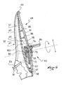
- a wall 90 covers the slider 72 on the side of the free face 48, the means immobilizing the slider 72 passing through the wall 90.
- the wall 90 strongly limits, or even totally, the arrival of foreign bodies at the level of cursor 72. Simultaneously the immobilization means is accessible to the user. So the Tilt adjustment of the rear support element can be done easily. The absence of body strangers let the cursor move easily.
- the wall 90 which covers the slider 72, is a reinforcement which extends longitudinally substantially from the attachment ends 42, 43 to the free end 44 of the rear support member 40.
- the reinforcement 90 extends substantially from the lateral edge 45 to the medial edge 46.
- the reinforcement 90 has a free face 91 opposite to an anterior face 92.
- the free face 91 is confuses with the free face 48 of the rear support element 40.
- the reinforcement 90 is the portion of the rearmost support member 40 the most remote and the largest. He gives 90 the rear support member 40 a large part of its mechanical strength.
- 90 reinforcement includes relatively rigid materials, such as metals or plastics.
- the free face 91 is substantially convex in the transverse direction, which allows the rear support member 40 to support the pulses from the lower leg of the user, and better accommodate the lower leg.
- the free face 91 has a continuity of curvature, which is conducive to driving easy because a possible obstacle tends to slide on the face 91 without clinging to it.
- powder snow which rubs the rear support member 40 is little, if any, adherent vis-à-vis of element 40. In other words deep snow penetration is improved.
- the thickness of the reinforcement 90 is substantially constant, to facilitate the manufacture of the rear support element, as well as the position of the slider 72. Indeed the screw 73 crosses the reinforcement 90 by a slot 93. The latter 93 is oriented longitudinally by relative to the rear support element 40, through the toothing 75, since the toothing 75 is located on the reinforcement 90. A constant thickness of the reinforcement 90 allows immobilization of the cursor 72, or a release, for the same number of turns of screws. This regardless of the position longitudinal screw 73 in the slot 93.
- a handle 94 associated with the screw 73 In order to allow tool-less handling, there is provided a handle 94 associated with the screw 73.
- the handle 94 is hinged relative to the screw 73.
- the handle 94 can be deployed to turn the screw 73, as is the case in Figure 6.
- the handle 94 can be folded down to reduce clutter, as is the case in the figures 1 to 5.
- any other mode of actuation of the screw can be provided, including the use of a tool.
- the slider 72 is movable relative to the reinforcement 90 which covers the slider 72. Since this reinforcement 90 constitutes a continuous part connected to the seat 3, the rear support member 40 is held in angular position when the slider 72 is immobilized.
- the slider 72 and the handle 94 are respectively on either side of the same wall or reinforcement 90.
- the slider 72 is on the side of the shoe, facing the face former 92, while the handle 94 is on the side of the free face 91, accessible to the user in all cases.
- the toothing 75 of the rear support element 40 is on the side of the shoe, on the anterior face 92.
- a means for stiffening. This comprises for example ribs 95, 96, 97, 98 projecting from relative to the anterior face 92.
- the ribs 95, 96, 97, 98 allow to keep a low mass for the rear support element 40.
- a hood 99 is provided. to form in part at least the bearing face 47 of the rear support element 40.
- the hood 99 rests on the ribs 95, 96, 97, 98, as well as on the anterior face 92. transmit the supports, from the lower leg of the user, to the wall or reinforcement 90. consequently these supports are transmitted to the stop 60.
- the cover 99 covers the slider 72 and the teeth 74, 75 on the side of the bearing face 47. the reinforcement 90, the cover 99 forms an enclosure 100 for the reception of the cursor 72.
- the enclosure is almost closed, with the exception of the slot 93 for the passage of the screw 73, and guides 70, 71 for the passage of the link 60.
- the slot 93 is reduced in size relative to the cursor 72, and the handle 94 at least partly covers the slot, so that the foreign bodies do not penetrate not substantially into the enclosure 100.
- the clearance between the link 60 and each guide is reduced, also making the passage of foreign bodies almost impossible.
- the adjustment of the position of the slider 72 is in good conditions.
- the invention is made from materials and according to implementation techniques known to those skilled in the art.
- cover wall whether formed by the reinforcement or by the cover, can present a relief such as that which would delimit a reduced enclosure for the cursor movement.
- the free face 48 would then have a hollow hump.
- one or more deformable plugs may be provided in the slot 93 traversed by the screw 73. These plugs would be more or less compressed according to the position of the screw in the slot. The plugs further improve the tightness of the enclosure 100.
Landscapes
- Footwear And Its Accessory, Manufacturing Method And Apparatuses (AREA)
- Road Paving Machines (AREA)
- Braking Arrangements (AREA)
Abstract
Description
- la figure 1 est une vue en perspective avant d'un dispositif d'accueil selon la forme de réalisation de l'invention,
- la figure 2 est une vue partielle du dispositif, similaire à la figure 1,
- la figure 3 est une vue de côté du dispositif de la figure 1,
- la figure 4 est une vue arrière du dispositif de la figure 1,
- la figure 5 est une vue avant partielle du dispositif de la figure 1,
- la figure 6 est une vue en coupe selon VI-VI de la figure 4.
Claims (10)
- Dispositif d'accueil (1) d'un pied ou d'une chaussure sur un engin de sport (2), le dispositif (1) comprenant une assise (3) associée à un élément d'appui arrière (40), l'élément d'appui arrière (40) présentant une face d'appui (47) opposée à une face libre (48, 91), l'élément d'appui arrière (40) étant monté rotatif par rapport à l'assise (3), une butée (60) limitant une rotation vers l'arrière de l'élément d'appui arrière (40), la butée (60) comprenant un curseur (72) mobile le long de l'élément d'appui arrière (40), ainsi qu'un moyen d'immobilisation du curseur (72) sur l'élément d'appui arrière (40),
caractérisé par le fait qu'une paroi (90) couvre le curseur (72) du côté de la face libre (48, 91), le moyen d'immobilisation traversant la paroi (90). - Dispositif d'accueil (1) selon la revendication 1, caractérisé par le fait que la paroi (90) est un renfort qui s'étend longitudinalement sensiblement depuis des extrémités d'attache (42, 43) jusqu'à une extrémité libre (44) de l'élément d'appui arrière (40), transversalement sensiblement depuis un bord latéral (45) jusqu'à un bord médial (46) de l'élément d'appui arrière (40), et en épaisseur entre une face libre (48, 91) et une face antérieure (92).
- Dispositif d'accueil (1) selon la revendication 1 ou 2, caractérisé par le fait que le moyen d'immobilisation du curseur (72) comprend une vis (73) qui traverse le renfort (90) par une fente (93).
- Dispositif d'accueil (1) selon l'une des revendications 1 à 3, caractérisé par le fait que le moyen d'immobilisation du curseur (72) comprend des dentures complémentaires (74, 75) respectivement sur le curseur (72) et sur la paroi (90).
- Dispositif d'accueil (1) selon la revendication 3 ou 4, caractérisé par le fait qu'une poignée (94) est associée à la vis (73), le curseur (72) et la poignée (94) étant respectivement de part et d'autre du renfort ou paroi (90).
- Dispositif d'accueil (1) selon l'une des revendications 1 à 5, caractérisé par le fait qu'un capot (99) forme en partie au moins la face d'appui (47) de l'élément d'appui arrière (40).
- Dispositif d'accueil (1) selon l'une des revendications 1 à 6, caractérisé par le fait que la face libre (48, 91) est sensiblement convexe dans le sens transversal.
- Dispositif d'accueil (1) selon l'une des revendications 1 à 7, caractérisé par le fait que la face libre (48, 91) présente une continuité de courbure.
- Dispositif d'accueil (1) selon la revendication 1, caractérisé par le fait que la paroi qui couvre le curseur (72) du côté de la face libre est un capot.
- Dispositif d'accueil (1) selon l'une des revendications 1 à 9, caractérisé par le fait qu'il comprend des liens (23, 24) pour maintenir de façon amovible la chaussure sur l'assise (3).
Applications Claiming Priority (4)
| Application Number | Priority Date | Filing Date | Title |
|---|---|---|---|
| FR0310366 | 2003-09-02 | ||
| FR0310366A FR2859109B1 (fr) | 2003-09-02 | 2003-09-02 | Dispositif de maintien d'un pied ou d'une chaussure sur un engin de sport |
| FR0409074A FR2859389B1 (fr) | 2003-09-02 | 2004-08-25 | Dispositif d'accueil d'un pied ou d'une chaussure sur un engin de sport |
| FR0409074 | 2004-08-25 |
Publications (2)
| Publication Number | Publication Date |
|---|---|
| EP1512441A1 true EP1512441A1 (fr) | 2005-03-09 |
| EP1512441B1 EP1512441B1 (fr) | 2008-03-12 |
Family
ID=34137711
Family Applications (1)
| Application Number | Title | Priority Date | Filing Date |
|---|---|---|---|
| EP04020352A Expired - Lifetime EP1512441B1 (fr) | 2003-09-02 | 2004-08-27 | Dispositif d'accueil d'un pied ou d'une chaussure sur un engin de sport |
Country Status (4)
| Country | Link |
|---|---|
| EP (1) | EP1512441B1 (fr) |
| AT (1) | ATE388742T1 (fr) |
| DE (1) | DE602004012359T2 (fr) |
| FR (1) | FR2859389B1 (fr) |
Cited By (1)
| Publication number | Priority date | Publication date | Assignee | Title |
|---|---|---|---|---|
| FR2896425A1 (fr) * | 2006-01-26 | 2007-07-27 | Salomon Sa | Dispositif d'accueil d'un pied ou d'une chaussure sur un engin de sport |
Citations (2)
| Publication number | Priority date | Publication date | Assignee | Title |
|---|---|---|---|---|
| FR2793156A1 (fr) * | 1999-05-07 | 2000-11-10 | Salomon Sa | Dispositif de retenue d'une chaussure sur une planche de glisse |
| US20030015857A1 (en) * | 2001-07-17 | 2003-01-23 | Piva S.R.L. | Leg support particularly for snowboard bindings |
-
2004
- 2004-08-25 FR FR0409074A patent/FR2859389B1/fr not_active Expired - Fee Related
- 2004-08-27 AT AT04020352T patent/ATE388742T1/de not_active IP Right Cessation
- 2004-08-27 EP EP04020352A patent/EP1512441B1/fr not_active Expired - Lifetime
- 2004-08-27 DE DE602004012359T patent/DE602004012359T2/de not_active Expired - Lifetime
Patent Citations (2)
| Publication number | Priority date | Publication date | Assignee | Title |
|---|---|---|---|---|
| FR2793156A1 (fr) * | 1999-05-07 | 2000-11-10 | Salomon Sa | Dispositif de retenue d'une chaussure sur une planche de glisse |
| US20030015857A1 (en) * | 2001-07-17 | 2003-01-23 | Piva S.R.L. | Leg support particularly for snowboard bindings |
Cited By (1)
| Publication number | Priority date | Publication date | Assignee | Title |
|---|---|---|---|---|
| FR2896425A1 (fr) * | 2006-01-26 | 2007-07-27 | Salomon Sa | Dispositif d'accueil d'un pied ou d'une chaussure sur un engin de sport |
Also Published As
| Publication number | Publication date |
|---|---|
| DE602004012359D1 (de) | 2008-04-24 |
| FR2859389A1 (fr) | 2005-03-11 |
| FR2859389B1 (fr) | 2006-01-20 |
| DE602004012359T2 (de) | 2009-03-12 |
| ATE388742T1 (de) | 2008-03-15 |
| EP1512441B1 (fr) | 2008-03-12 |
Similar Documents
| Publication | Publication Date | Title |
|---|---|---|
| EP1512440B1 (fr) | Dispositif de maintien d'un pied ou d'une chaussure sur un engin de sport | |
| EP1559454B1 (fr) | Dispositif d'accueil d'un pied ou d'une chaussure sur un engin de sport | |
| FR2634721A1 (fr) | Dispositif de fixation d'une chaussure sur une pedale de bicyclette | |
| EP1120139A1 (fr) | Dispositif d'interface pour engin de sport | |
| EP1103290B1 (fr) | Fixation de surf | |
| EP1108450B1 (fr) | Dispositif de retenue d'une chaussure sur une planche de glisse | |
| EP1254684B1 (fr) | Perfectionnement pour dispositif de retenue d'une chaussure sur une planche de glisse sur neige du type surf | |
| FR2835439A1 (fr) | Fixation pour appareils de sport, notamment pour une planche de surf des neiges | |
| EP0956886B1 (fr) | Interface de liaison entre une chaussure et une planche de glisse | |
| FR2896425A1 (fr) | Dispositif d'accueil d'un pied ou d'une chaussure sur un engin de sport | |
| EP1104251B1 (fr) | Chaussure de ski de fond | |
| FR2958556A1 (fr) | Dispositif d'accueil d'un pied ou d'une chaussure sur un engin de glisse. | |
| EP1512441B1 (fr) | Dispositif d'accueil d'un pied ou d'une chaussure sur un engin de sport | |
| FR2834475A1 (fr) | Dispositif de retenue d'une chaussure sur un engin de sport | |
| EP1433504A1 (fr) | Dispositif de retenue d'une chaussure sur un engin de sport | |
| EP3741436B1 (fr) | Dispositif de fixation pour fixer une chaussure à une planche de glisse | |
| FR2769239A1 (fr) | Dispositif de retenue d'une chaussure sur une planche de glisse destinee a la pratique du surf sur neige | |
| EP1530987B1 (fr) | Fixation de surf | |
| WO2004089481A2 (fr) | Fixation avec un organe de liaison en deux parties | |
| FR3096273A1 (fr) | Dispositif de fixation pour fixer une chaussure à une planche de glisse | |
| EP1923105B1 (fr) | Dispositif d'accueil d'un pied ou d'une chaussure sur un engin de sport | |
| FR2879940A1 (fr) | Article de sport comprenant une premiere piece et une deuxieme piece prevues pour tourner a plat l'une sur l'autre | |
| EP1468711A1 (fr) | Dispositif de retenue d'une chaussure sur un engin de sport | |
| FR3163534A1 (fr) | Dispositif de verrouillage pour une chaussure de ski | |
| FR2878757A1 (fr) | Dispositif de maintien d'un pied ou d'une chaussure sur un engin de sport |
Legal Events
| Date | Code | Title | Description |
|---|---|---|---|
| PUAI | Public reference made under article 153(3) epc to a published international application that has entered the european phase |
Free format text: ORIGINAL CODE: 0009012 |
|
| AK | Designated contracting states |
Kind code of ref document: A1 Designated state(s): AT BE BG CH CY CZ DE DK EE ES FI FR GB GR HU IE IT LI LU MC NL PL PT RO SE SI SK TR |
|
| AX | Request for extension of the european patent |
Extension state: AL HR LT LV MK |
|
| 17P | Request for examination filed |
Effective date: 20050902 |
|
| AKX | Designation fees paid |
Designated state(s): AT CH DE FR LI |
|
| 17Q | First examination report despatched |
Effective date: 20061208 |
|
| GRAP | Despatch of communication of intention to grant a patent |
Free format text: ORIGINAL CODE: EPIDOSNIGR1 |
|
| GRAS | Grant fee paid |
Free format text: ORIGINAL CODE: EPIDOSNIGR3 |
|
| GRAA | (expected) grant |
Free format text: ORIGINAL CODE: 0009210 |
|
| AK | Designated contracting states |
Kind code of ref document: B1 Designated state(s): AT CH DE FR LI |
|
| RIN1 | Information on inventor provided before grant (corrected) |
Inventor name: COUDERC, BERNARD |
|
| REG | Reference to a national code |
Ref country code: CH Ref legal event code: EP |
|
| REF | Corresponds to: |
Ref document number: 602004012359 Country of ref document: DE Date of ref document: 20080424 Kind code of ref document: P |
|
| PG25 | Lapsed in a contracting state [announced via postgrant information from national office to epo] |
Ref country code: AT Free format text: LAPSE BECAUSE OF FAILURE TO SUBMIT A TRANSLATION OF THE DESCRIPTION OR TO PAY THE FEE WITHIN THE PRESCRIBED TIME-LIMIT Effective date: 20080312 |
|
| PGFP | Annual fee paid to national office [announced via postgrant information from national office to epo] |
Ref country code: CH Payment date: 20080918 Year of fee payment: 5 |
|
| PLBE | No opposition filed within time limit |
Free format text: ORIGINAL CODE: 0009261 |
|
| STAA | Information on the status of an ep patent application or granted ep patent |
Free format text: STATUS: NO OPPOSITION FILED WITHIN TIME LIMIT |
|
| 26N | No opposition filed |
Effective date: 20081215 |
|
| REG | Reference to a national code |
Ref country code: FR Ref legal event code: CJ Ref country code: FR Ref legal event code: CA |
|
| REG | Reference to a national code |
Ref country code: CH Ref legal event code: PL |
|
| PG25 | Lapsed in a contracting state [announced via postgrant information from national office to epo] |
Ref country code: LI Free format text: LAPSE BECAUSE OF NON-PAYMENT OF DUE FEES Effective date: 20090831 Ref country code: CH Free format text: LAPSE BECAUSE OF NON-PAYMENT OF DUE FEES Effective date: 20090831 |
|
| PGFP | Annual fee paid to national office [announced via postgrant information from national office to epo] |
Ref country code: FR Payment date: 20120823 Year of fee payment: 9 Ref country code: DE Payment date: 20120822 Year of fee payment: 9 |
|
| PG25 | Lapsed in a contracting state [announced via postgrant information from national office to epo] |
Ref country code: DE Free format text: LAPSE BECAUSE OF NON-PAYMENT OF DUE FEES Effective date: 20140301 |
|
| REG | Reference to a national code |
Ref country code: DE Ref legal event code: R119 Ref document number: 602004012359 Country of ref document: DE Effective date: 20140301 |
|
| REG | Reference to a national code |
Ref country code: FR Ref legal event code: ST Effective date: 20140430 |
|
| PG25 | Lapsed in a contracting state [announced via postgrant information from national office to epo] |
Ref country code: FR Free format text: LAPSE BECAUSE OF NON-PAYMENT OF DUE FEES Effective date: 20130902 |