EP1512430B1 - Device for sleep-apnea treatment - Google Patents
Device for sleep-apnea treatment Download PDFInfo
- Publication number
- EP1512430B1 EP1512430B1 EP04090229A EP04090229A EP1512430B1 EP 1512430 B1 EP1512430 B1 EP 1512430B1 EP 04090229 A EP04090229 A EP 04090229A EP 04090229 A EP04090229 A EP 04090229A EP 1512430 B1 EP1512430 B1 EP 1512430B1
- Authority
- EP
- European Patent Office
- Prior art keywords
- sleep
- apnea
- medical device
- signal
- unit
- Prior art date
- Legal status (The legal status is an assumption and is not a legal conclusion. Google has not performed a legal analysis and makes no representation as to the accuracy of the status listed.)
- Not-in-force
Links
Images

Classifications
-
- A—HUMAN NECESSITIES
- A61—MEDICAL OR VETERINARY SCIENCE; HYGIENE
- A61B—DIAGNOSIS; SURGERY; IDENTIFICATION
- A61B5/00—Measuring for diagnostic purposes; Identification of persons
- A61B5/05—Detecting, measuring or recording for diagnosis by means of electric currents or magnetic fields; Measuring using microwaves or radio waves
- A61B5/053—Measuring electrical impedance or conductance of a portion of the body
- A61B5/0538—Measuring electrical impedance or conductance of a portion of the body invasively, e.g. using a catheter
-
- A—HUMAN NECESSITIES
- A61—MEDICAL OR VETERINARY SCIENCE; HYGIENE
- A61B—DIAGNOSIS; SURGERY; IDENTIFICATION
- A61B5/00—Measuring for diagnostic purposes; Identification of persons
- A61B5/0002—Remote monitoring of patients using telemetry, e.g. transmission of vital signals via a communication network
- A61B5/0031—Implanted circuitry
-
- A—HUMAN NECESSITIES
- A61—MEDICAL OR VETERINARY SCIENCE; HYGIENE
- A61B—DIAGNOSIS; SURGERY; IDENTIFICATION
- A61B5/00—Measuring for diagnostic purposes; Identification of persons
- A61B5/02—Detecting, measuring or recording pulse, heart rate, blood pressure or blood flow; Combined pulse/heart-rate/blood pressure determination; Evaluating a cardiovascular condition not otherwise provided for, e.g. using combinations of techniques provided for in this group with electrocardiography or electroauscultation; Heart catheters for measuring blood pressure
- A61B5/02028—Determining haemodynamic parameters not otherwise provided for, e.g. cardiac contractility or left ventricular ejection fraction
-
- A—HUMAN NECESSITIES
- A61—MEDICAL OR VETERINARY SCIENCE; HYGIENE
- A61B—DIAGNOSIS; SURGERY; IDENTIFICATION
- A61B5/00—Measuring for diagnostic purposes; Identification of persons
- A61B5/103—Detecting, measuring or recording devices for testing the shape, pattern, colour, size or movement of the body or parts thereof, for diagnostic purposes
- A61B5/11—Measuring movement of the entire body or parts thereof, e.g. head or hand tremor, mobility of a limb
- A61B5/1112—Global tracking of patients, e.g. by using GPS
-
- A—HUMAN NECESSITIES
- A61—MEDICAL OR VETERINARY SCIENCE; HYGIENE
- A61B—DIAGNOSIS; SURGERY; IDENTIFICATION
- A61B5/00—Measuring for diagnostic purposes; Identification of persons
- A61B5/103—Detecting, measuring or recording devices for testing the shape, pattern, colour, size or movement of the body or parts thereof, for diagnostic purposes
- A61B5/11—Measuring movement of the entire body or parts thereof, e.g. head or hand tremor, mobility of a limb
- A61B5/1118—Determining activity level
-
- A—HUMAN NECESSITIES
- A61—MEDICAL OR VETERINARY SCIENCE; HYGIENE
- A61B—DIAGNOSIS; SURGERY; IDENTIFICATION
- A61B5/00—Measuring for diagnostic purposes; Identification of persons
- A61B5/103—Detecting, measuring or recording devices for testing the shape, pattern, colour, size or movement of the body or parts thereof, for diagnostic purposes
- A61B5/11—Measuring movement of the entire body or parts thereof, e.g. head or hand tremor, mobility of a limb
- A61B5/1123—Discriminating type of movement, e.g. walking or running
-
- A—HUMAN NECESSITIES
- A61—MEDICAL OR VETERINARY SCIENCE; HYGIENE
- A61B—DIAGNOSIS; SURGERY; IDENTIFICATION
- A61B5/00—Measuring for diagnostic purposes; Identification of persons
- A61B5/103—Detecting, measuring or recording devices for testing the shape, pattern, colour, size or movement of the body or parts thereof, for diagnostic purposes
- A61B5/11—Measuring movement of the entire body or parts thereof, e.g. head or hand tremor, mobility of a limb
- A61B5/1126—Measuring movement of the entire body or parts thereof, e.g. head or hand tremor, mobility of a limb using a particular sensing technique
-
- A—HUMAN NECESSITIES
- A61—MEDICAL OR VETERINARY SCIENCE; HYGIENE
- A61B—DIAGNOSIS; SURGERY; IDENTIFICATION
- A61B5/00—Measuring for diagnostic purposes; Identification of persons
- A61B5/48—Other medical applications
- A61B5/4806—Sleep evaluation
- A61B5/4818—Sleep apnoea
-
- A—HUMAN NECESSITIES
- A61—MEDICAL OR VETERINARY SCIENCE; HYGIENE
- A61N—ELECTROTHERAPY; MAGNETOTHERAPY; RADIATION THERAPY; ULTRASOUND THERAPY
- A61N1/00—Electrotherapy; Circuits therefor
- A61N1/18—Applying electric currents by contact electrodes
- A61N1/32—Applying electric currents by contact electrodes alternating or intermittent currents
- A61N1/36—Applying electric currents by contact electrodes alternating or intermittent currents for stimulation
- A61N1/362—Heart stimulators
- A61N1/365—Heart stimulators controlled by a physiological parameter, e.g. heart potential
- A61N1/36514—Heart stimulators controlled by a physiological parameter, e.g. heart potential controlled by a physiological quantity other than heart potential, e.g. blood pressure
-
- A—HUMAN NECESSITIES
- A61—MEDICAL OR VETERINARY SCIENCE; HYGIENE
- A61B—DIAGNOSIS; SURGERY; IDENTIFICATION
- A61B2562/00—Details of sensors; Constructional details of sensor housings or probes; Accessories for sensors
- A61B2562/02—Details of sensors specially adapted for in-vivo measurements
- A61B2562/0219—Inertial sensors, e.g. accelerometers, gyroscopes, tilt switches
-
- A—HUMAN NECESSITIES
- A61—MEDICAL OR VETERINARY SCIENCE; HYGIENE
- A61B—DIAGNOSIS; SURGERY; IDENTIFICATION
- A61B5/00—Measuring for diagnostic purposes; Identification of persons
- A61B5/02—Detecting, measuring or recording pulse, heart rate, blood pressure or blood flow; Combined pulse/heart-rate/blood pressure determination; Evaluating a cardiovascular condition not otherwise provided for, e.g. using combinations of techniques provided for in this group with electrocardiography or electroauscultation; Heart catheters for measuring blood pressure
- A61B5/0205—Simultaneously evaluating both cardiovascular conditions and different types of body conditions, e.g. heart and respiratory condition
-
- A—HUMAN NECESSITIES
- A61—MEDICAL OR VETERINARY SCIENCE; HYGIENE
- A61B—DIAGNOSIS; SURGERY; IDENTIFICATION
- A61B5/00—Measuring for diagnostic purposes; Identification of persons
- A61B5/02—Detecting, measuring or recording pulse, heart rate, blood pressure or blood flow; Combined pulse/heart-rate/blood pressure determination; Evaluating a cardiovascular condition not otherwise provided for, e.g. using combinations of techniques provided for in this group with electrocardiography or electroauscultation; Heart catheters for measuring blood pressure
- A61B5/024—Detecting, measuring or recording pulse rate or heart rate
- A61B5/0245—Detecting, measuring or recording pulse rate or heart rate by using sensing means generating electric signals, i.e. ECG signals
-
- A—HUMAN NECESSITIES
- A61—MEDICAL OR VETERINARY SCIENCE; HYGIENE
- A61B—DIAGNOSIS; SURGERY; IDENTIFICATION
- A61B5/00—Measuring for diagnostic purposes; Identification of persons
- A61B5/02—Detecting, measuring or recording pulse, heart rate, blood pressure or blood flow; Combined pulse/heart-rate/blood pressure determination; Evaluating a cardiovascular condition not otherwise provided for, e.g. using combinations of techniques provided for in this group with electrocardiography or electroauscultation; Heart catheters for measuring blood pressure
- A61B5/026—Measuring blood flow
- A61B5/029—Measuring or recording blood output from the heart, e.g. minute volume
-
- A—HUMAN NECESSITIES
- A61—MEDICAL OR VETERINARY SCIENCE; HYGIENE
- A61B—DIAGNOSIS; SURGERY; IDENTIFICATION
- A61B5/00—Measuring for diagnostic purposes; Identification of persons
- A61B5/07—Endoradiosondes
-
- A—HUMAN NECESSITIES
- A61—MEDICAL OR VETERINARY SCIENCE; HYGIENE
- A61B—DIAGNOSIS; SURGERY; IDENTIFICATION
- A61B5/00—Measuring for diagnostic purposes; Identification of persons
- A61B5/24—Detecting, measuring or recording bioelectric or biomagnetic signals of the body or parts thereof
- A61B5/316—Modalities, i.e. specific diagnostic methods
- A61B5/318—Heart-related electrical modalities, e.g. electrocardiography [ECG]
- A61B5/346—Analysis of electrocardiograms
- A61B5/349—Detecting specific parameters of the electrocardiograph cycle
- A61B5/363—Detecting tachycardia or bradycardia
-
- A—HUMAN NECESSITIES
- A61—MEDICAL OR VETERINARY SCIENCE; HYGIENE
- A61B—DIAGNOSIS; SURGERY; IDENTIFICATION
- A61B5/00—Measuring for diagnostic purposes; Identification of persons
- A61B5/68—Arrangements of detecting, measuring or recording means, e.g. sensors, in relation to patient
- A61B5/6846—Arrangements of detecting, measuring or recording means, e.g. sensors, in relation to patient specially adapted to be brought in contact with an internal body part, i.e. invasive
- A61B5/6847—Arrangements of detecting, measuring or recording means, e.g. sensors, in relation to patient specially adapted to be brought in contact with an internal body part, i.e. invasive mounted on an invasive device
- A61B5/686—Permanently implanted devices, e.g. pacemakers, other stimulators, biochips
Definitions
- the invention relates to a medical device for implantation in a body, with a stimulation unit which is designed to generate an electrical stimulation pulse in response to an apnea therapy signal, a sleep detector unit having at least one signal input, which is formed as a function of at least recognize an input signal a sleep state of the body and to generate a sleep signal corresponding to a sleep detection result.
- the medical device for implantation in a body also referred to below as an implantable medical device, also has an apnea detector unit which is designed to recognize a sleep apnea as a function of at least one body signal caused by the body and an apnea signal which corresponds to an apnea recognition result.
- the implantable medical device also has a therapy unit, which is at least indirectly connected to the sleep detector unit and with the apnea detector unit and designed to generate at least one apnea therapy signal depending on the apnea signal and the sleep signal, which therapy information optionally for the prevention of sleep apnea, Treatment of sleep apnea or both represents and send this to the stimulation unit.
- a therapy unit which is at least indirectly connected to the sleep detector unit and with the apnea detector unit and designed to generate at least one apnea therapy signal depending on the apnea signal and the sleep signal, which therapy information optionally for the prevention of sleep apnea, Treatment of sleep apnea or both represents and send this to the stimulation unit.
- Such a system has a particular advantage for patients in whom a pacemaker implantation is already indicated. Such a system may also be beneficial for patients suffering from sleep apnea without other indications for implantation.
- a significant proportion of the population is affected by respiratory disorders.
- Such a respiratory disorder is, for example, sleep apnea, a temporary respiratory failure.
- the most common manifestation is obstructive sleep apnea, which affects approximately 6% of the male population over the age of 40 years. In obstructive sleep apnea, the upper airways collapse and occlude, preventing the passage of breathing air. This can occur repeatedly during sleep.
- sleep apnea Another manifestation of sleep apnea is the central sleep apnea syndrome.
- This syndrome the airways remain open, but the central control of the respiratory muscles is adversely affected. While this form of apnea is observed in about 10 to 20% of all sleep apnea sufferers, it has a high preponderance in patients with heart failure.
- Such patients also have the Cheyne-Stokes respiration, which is a periodic decrease and increase in respiratory amplitude, also referred to as respiratory depth.
- the patient in this case has periods of lesser depth of breath, that is, central apnea, and periods of increased depth of breath, also referred to as hyperventilation.
- These respiratory dysfunctions affect heart rate, hemodynamics, and blood pressure.
- the apnea periods may stimulate an increase in sympathetic activity, which may adversely affect the heart.
- the interaction of sleep apnea with heart failure significantly reduces the quality of life and the patient's performance. Therefore, it is essential that sleep apnea be monitored, identified and treated in such cases.
- respiratory dysfunctions such as sleep apnea
- Prior art devices include the use of externally mounted respiratory sensors and respiratory masks.
- sleep apnea is treated by artificial respirators that control breathing and force inhalation and exhalation.
- these devices significantly limit the quality of life. Since this therapy depends on patient cooperation, the intrusive nature of this device may prevent its ongoing use.
- Atrial overexertion was set at about 15 beats per minute above the patient's average heart rate at night.
- the observed apnea-hypopnea index dropped more than 50% during the nights with continuous pacemaker pacing.
- the Apnea Hypopnea Index is a measure of the frequency of the stunted or slowed respiratory rate Night. The reason for the observed improvement is not cited, but the pacemaker apparatus improved both obstructive and central apnea.
- the St. Jude Medical Center published a new study evaluating pacemaker therapy for sleep apnea.
- the plan was to evaluate the impact of increased pacing rate during a resting period, but the study is apparently limited to pacemaker patients diagnosed with sleep apnea.
- the St. Jude study wants to use a secret algorithm to download into a patient's pacemaker.
- an implantable cardiac stimulator which is capable of detecting sleep apnea and then increasing the rate of pacing.
- a pacemaker which includes a position and motion sensor for adjusting the rate of stimulation to the physiological needs of the patient.
- the use of the heartbeat volume is known as an input parameter for adjusting or adjusting the pacing rate.
- a tidal volume value is calculated from the frequency and relative amplitude of a respiratory signal, which can be determined from a measurement of intrathoracic impedance.
- the St. Jude algorithm uses a time of day clock to turn pacemaker therapy on and off.
- an algorithm based on reading a time of day clock can cause problems when the patient is traveling through time zones, as a result of which time changes occur (as well as such time changes to gain daylight time), and when the patient has sleep disturbances.
- the apnea detector unit includes an apnea weighting discriminator having at least one input for a body signal.
- the apnea weighting discriminator is configured to evaluate the body signal according to a predetermined apnea weighting function and to generate an apnea signal representing a sleep apnea.
- the sleep detector unit preferably includes a sleep weighting discriminator having at least one input for an input signal, wherein the sleep weighting discriminator is configured to evaluate the input signal according to a predetermined sleep weighting function and generate a sleep signal representing a sleep state ,
- the sleep weighting discriminator and / or the apnea weighting discriminator includes fuzzy logic.
- the medical device preferably includes a time of day clock associated with the sleep detector unit and thus available as an input parameter for deciding whether a sleep status exists or not.
- the medical device comprises a world time zone detector having a satellite receiver, the world time zone detector operably connected to the time of day clock and configured to receive satellite signals to position on the earth by evaluating the satellite signals determine and generate from the position on the earth a world time zone signal and send it to the time of day clock, which is adapted to correct the time of day accordingly.
- the satellite receiving system can determine the position in the form of coordinates. Based on the coordinates, the satellite receiving system can make an assignment to a world time zone in which the wearer of the medical device is currently located.
- the satellite receiving system is preferably associated with the time of day clock and thus can effect a correction of the time of day when the wearer of the medical device is in a different time zone.
- the satellite receiving system includes the Global Positioning System (GPS) known in the art.
- GPS Global Positioning System
- the stimulation unit is configured to generate an electrical stimulation pulse which is suitable for stimulating a tissue such that a depolarization threshold for muscle contraction is exceeded.
- the stimulation unit comprises respiratory musculature stimulation unit which is designed to generate an electrical stimulation pulse for stimulation of the diaphragm or the thorax musculature.
- the implantable medical device has an outlet for connecting respiratory muscle stimulation electrodes.
- the implantable medical device comprises a pacemaker or defibrillator.
- the therapy unit may be connected to the pacemaker or defibrillator and send therapeutic signals containing stimulation information thereto.
- the pacemaker is thus an executive agent for the treatment of sleep apnea.
- An exemplary embodiment of an activity sensor is an accelerometer or closed loop stimulation (CLS).
- a resting or load state of the body is derived from an intracardiac impedance signal during a closed-loop stimulation.
- This technique is in the article " Closed Loop Stimulation - A New Pacemaker - Concept for Frequency Adaptation Using a Contractility Sensor "in Journal Kardiol, 1999, Vol. 6, Iss.1, pp. 21-25 explained.
- the implantable medical device in a preferred embodiment, has an intracardiac impedance sensor connected to the sleep detector and configured to detect resting of the body based on intracardiac impedance and to generate a resting state signal representative of the resting state of the body.
- the sensor for detecting the intracardiac impedance may also be designed as a contractility sensor.
- the device can advantageously use the CLS intracardiac impedance sensor on devices with CLS to divert an intracardiac impedance signal from the CLS.
- An acceleration sensor can advantageously be designed as a triaxial acceleration sensor in which the directional axes of the detectable accelerations form an orthogonal system and which is operatively connected to the sleep detector and designed to generate an acceleration time signal representing an acceleration.
- a body movement can be evaluated in such a way that the implantable medical device can distinguish between normal daily movement sequences and, for example, rolling movements during sleep when evaluating the time signals of the acceleration sensor on the basis of preferably occurring directions of acceleration.
- the implantable medical device preferably has an acceleration pattern classifier, which is formed on the basis of predetermined acceleration patterns, which are in each case for all three axes of motion can be stored to distinguish body movements during sleep from those during a daily routine.
- the acceleration pattern classifier is connected on the output side to the sleep detector unit and input side to the accelerometer and configured to evaluate an acceleration time signal and to detect predetermined acceleration patterns in the acceleration time signal, classify them, and an acceleration pattern signal representing an acceleration pattern to generate and output this output side.
- the medical device may also have a speed sensor.
- the acceleration patterns provided for classification may be time signals or power spectra, in the case of power spectra the acceleration pattern classifier has on the input side an FFT analyzer (FFT: Fast Fourier Transform), which is designed to continuously supply acceleration pattern power spectra from an acceleration time signal and send them to the accelerator pattern classifier.
- FFT Fast Fourier Transform
- the storage of power spectra for classification comparison is advantageous in comparison to the storage of time signals particularly economical in storage space consumption.
- the implantable medical device has a time of day clock which is connected to the sleep detector unit.
- the implantable medical device has at least one activity sensor to increase the accuracy of detection, whether sleep has begun or ended, and whether pacing therapy should be started or stopped.
- the algorithm In order to activate the stimulation algorithm of the present invention, which means switching the stimulation protocol to "on", the algorithm requires that the time of day clock must indicate that the time is within a predetermined time interval for sleep and that at least one activity sensor is missing indicates a movement of the patient.
- the stimulation protocol in this case means an increase in the heart rate.
- an increase of the stimulation rate with a rising edge over a period of 10 minutes is provided according to the invention.
- the overall increase in pacing rate is 10 beats per minute and is achieved by increasing the pacing rate from one beats per minute to 10 minutes.
- the sleep algorithm of the present invention may disable the pacing protocol when the predetermined time interval is reached and motion is detected by at least one activity sensor, just as a preferred sleep algorithm may increase the pacing rate in accordance with a ramping on pacing protocol, the preferred sleep algorithm may be Lower the stimulation rate to a similar absolute rate, for example, if the stimulation rate increases by one beat per minute at power up, the decrease should also be one beat per minute on exit.
- the different sensing means may respectively a weighting factor and the prevalence of "NO MOTION" weighted signals can be assigned, which may be sufficient.
- the ability to extracorporeally program the rate of increase / decrease of the stimulation rate and the predetermined period of sleep time is considered essential.
- the algorithm also reads the patient's breathing pattern via the Minute Ventilation waveform or the Closed Loop Stimulation (CLS) waveform to detect sleep apnea.
- CLS Closed Loop Stimulation
- stimulation can only be switched to "on” via the recognition of a sleep apnea.
- a simple position detector is formed, in which case the status of the position detector may be used in a part of the sleep algorithm to detect if sleep has begun.
- An implantable monitoring system of the present invention overcomes all limits of previously known systems.
- the system can monitor respiration and send respiratory information with other diagnostic data to a remote monitoring center. In this way, a physician is able to monitor the patient without continuously monitoring the patient.
- the respiratory monitor may be integrated with a therapeutic device which is an implantable pacemaker or defibrillator (ICD, ICD: Implantable Cardioverter / Defibrillator) or it may operate as a stand-alone diagnostic device.
- ICD implantable pacemaker or defibrillator
- Breathing is measured via the intrathoracic impedance.
- sleep apnea therapy can be used in a resynchronization therapy using a cardiac pacemaker or defibrillator (ICD) for heart failure patients.
- ICD defibrillator
- the implantable respiratory monitor includes means for measuring impedance, a means for long distance telemetry (LDT), means for storing data, means for measuring a cardiac action signal, and a central control unit.
- LDT long distance telemetry
- Many of the monitors may also include an electrotherapeutic module, such as a pacemaker, a defibrillator (ICD), or both.
- ICD defibrillator
- the means for measuring the impedance may inject a sub-threshold electrical current between two electrodes selected from the available leads.
- the current can consist of biphasic pulses with constant amplitude.
- a pair of electrodes can be used.
- the measured voltage in this case is proportional to the impedance of the tissue in the measuring region.
- the current and voltage electrodes are the same electrodes.
- the voltage is amplified and filtered.
- a bandpass filter is preferred for this purpose.
- the filter may be selected to pass the respiratory signal but attenuate higher and lower frequency components.
- the medical device preferably comprises an oxygen sensor which is connected to the apnea detector unit and configured to determine an oxygen concentration in blood and to generate a blood oxygen signal representing the blood oxygen concentration.
- the oxygen concentration in blood thus serves as input for the apnea detector unit.
- the implantable medical device has a respiratory minute volume detection unit associated with the apnea detector unit connected is.
- the respiratory minute volume acquisition unit preferably contains means for determining the thoracic impedance.
- the thoracic impedance To detect respiration, the thoracic impedance must be determined.
- the impedance of the thorax changes during the respiratory cycles because the electrical conductivity of the lungs changes according to a different air content.
- the thoracic impedance also changes according to geometric differences.
- a preferred embodiment for a thoracic impedance detector is a tripolar measurement configuration utilizing the housing or can of the implant as a common electrode for current and voltage.
- a current is injected between the can and a ring electrode of the right ventricular lead or the left ventricular lead.
- the resulting voltage is measured between the tip of the electrode and the can, so that, as it were, the impedance of the thoracic tissue is measured.
- a lead for stimulation of the left ventricle either a coronary sinus lead or epicardial leads can be used with the appropriate tripolar configuration. In this case, the left part of the lung is included in the measurement region.
- a defibrillator lead (ICD lead), including the excitation coil may also be used for impedance measurements.
- the medical device has a heartbeat volume detection unit which is connected to the sleep detector unit and / or the therapy unit and configured to determine a heartbeat volume and to generate a heartbeat volume signal representing the heartbeat volume.
- the heartbeat volume can thus serve as an input to sleep detection or as an actual state variable for the therapy unit for regulating the heartbeat volume.
- the position sensor comprises at least two switching contacts and at least one electrically conductive ball which is arranged so as to electrically connect or disconnect the switching contacts depending on the inclination of the position sensor.
- the electrically conductive balls are preferably metal balls.
- a position sensor may include carbon spheres instead of the metal spheres.
- the carbon spheres contain compressed activated carbon dust, more preferably additionally a binder.
- the advantage of using the activated carbon spheres is that the number of carbon spheres involved in the short circuit depends on the positional angle of the position sensor relative to the horizontal one. This results in a function of the angular position, a different electrical resistance between the contacts of the position sensor.
- a ball material having a predetermined ohmic resistance may also be used.
- such balls are plastic balls or glass balls, which are vapor-deposited with a thin metal layer. The conductivity of the metal layer can be adjusted via the layer thickness and the textural properties.
- the position sensor may also be a Hall probe, which is designed to generate a Hall voltage as a function of its orientation in the earth's magnetic field.
- a position sensor according to the invention may also be a mercury switch known from the prior art.
- the remote viewing system which can be used with the present invention is well known in the art.
- the implant may send diagnostic data via the long-distance telemetry means (LDTM) to a device outside the patient, typically a device positioned laterally of a patient bed. From there, the data is sent to a central service center where a doctor can access the data.
- LDTM long-distance telemetry means
- the respiratory signal of a patient provides many parameters that can be extracted for diagnostic purposes. These data are stored in the implant and can be sent in a compressed form. The stored values can also be queried by an external device from the doctor. The external device can display the received data on a display in the form of numbers, trends, histograms or similar displays. For remote monitoring, the data is compressed into long-term averages, numerical values, etc., which are sent, for example, every 24 hours to a service center or a normal base.
- the device may be equipped to allow the patient to initiate a shipment.
- the intended device according to the invention may also be equipped with threshold switches based on various possible alarm criteria.
- apnea statistics information can be extracted from the respiratory signal and stored as apnea statistics information. These can be, but are not limited to, the following parameters:
- Respiratory rate Respiratory minute volume (relative to a reference value); Count of breathing pauses (or apnea events); Duration of breathing breaks; Counter of hyperventilation phases; Duration of hyperventilation phases; Classification of respiratory phases (normal, obstructive apnea, central apnea, hyperventilation, Cheyne-Stokes respiration). Monitoring of pulmonary edema is also conceivable.
- Cardiac action signals detected by the implant may also be correlated with the respiratory signals. This is particularly important for the monitoring of central sleep apnea and for patients with heart failure who suffer from sleep apnea.
- Some of the heart signal data may include, but is not limited to, the heart rate, event counters, etc. Changes in heart rate may prove particularly useful in conjunction with respiratory data since it has been known that obstructive sleep apnea is often accompanied by alternating phases of bradycardia and tachycardia.
- the diagnostic functionality of the implant may be combined with therapeutic options, such as atrial overstimulation.
- the respiratory sensor may trigger a pacing therapy when apnea has been detected.
- the device can also be used as a therapy monitor. A long-term success or short-term success of pacing therapy can be monitored. In addition, drug therapy corresponding to respiratory dysfunction associated with the implant may be used.
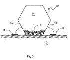
- the Figures 3 . 4 and 5 show exemplary embodiments of position sensors.
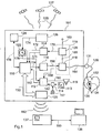
- FIG. 12 shows an implantable medical device 101 having a central control unit 110, a sleep detector unit 112, an apnea detector unit 114, a pacemaker unit 118 and an impedance sensor 120.
- the implantable medical device 101 also has a stimulation electrode output 131 which is connected via a connection lead 164 is connected to the pacing unit 118.
- Shown is also a heart 132, an electrode lead 130, which opens into the right atrium of the heart 132 and at the distal end portion of a ring electrode 134 and a tip electrode 136 is attached.
- the impedance sensor 120 is configured to flow current between the housing of the implantable medical device 101 and the ring electrode 134 to detect intrathoracic impedance and to detect a resulting voltage between the housing and the tip electrode 136.
- the impedance sensor 120 is connected via a housing line 169 to the housing of the implantable medical device 101 and connected via a connecting line 168 to the pacemaker unit 118, wherein the pacemaker unit 118 is formed, during a pause pause, an electrical connection between the Impendanzsensor 120th and the ring electrode 134 and the tip electrode 136 when the electrode lead 130 is connected to the stimulation output 131 of the implantable medical device 101.
- the apnea detector unit 114 is connected via a connecting line 170 to the impedance sensor 120 and designed to evaluate the time course of an intrathoracic impedance signal detected by the impedance sensor 120 and to generate a respiration signal, to evaluate this respiration signal according to its time course and to generate a corresponding, for example, breathing break information. Generate evaluation result.
- the apnea detector unit 114 can generate an apnea detector signal which represents the evaluation result, for example in the form of apnea status information and apnea therapy information, and sends this to the central control unit 110.
- the apnea detector unit 114 is connected on the output side via a connecting line 172 to the central control unit 110.
- the apnea detector unit 114 is also connected to the central control unit 110 for transmitting apnea statistics information via a connection line 171 and configured to generate a statistical evaluation result of the breathing signal and an apnea statistics signal representing the evaluation result via the connection line 171 to the central control unit 110 to send.
- the apnea statistics signal may include the following parameters: Respiration rate: Trend, histogram, minimum, maximum, mean, respiratory amplitude; Respiratory minute ventilation: Trend, histogram, minimum, maximum, mean; Apnea events: Absolute number, number per night; Duration of the Apnea events: Trend, histogram, minimum, maximum, mean, total during one night; Number of hyperventilation phases: Absolute number, number per night; Classification of the respiratory phases: normal breathing, obstructive apnea, central apnea, hyperventilation, Cheyne-Stokes respiration.
- the central control unit 110 is designed, for example, as a programmable microprocessor and can execute a control program implemented therein.
- the sleep detector unit 112 is designed to receive signals as a function of the input side via the connecting lines 151, 158, 160, 162, and 176, to evaluate them, to generate a sleep signal corresponding to the evaluation result and to output this via the connecting line 152 to the central control unit 110 to send.
- the sleep detector unit 112 is connected on the input side via a heart rate connection line 158 to the pacemaker unit 118, which has on the output side a heart rate signal corresponding to a detected heart rate generated and this can send via the connection line 158 to the sleep detector unit 112.
- the sleep detector unit 112 is connected on the input side via a connecting line 160 to a position sensor 115, which is designed to change its electrical resistance as a function of its angular position in relation to the horizontal.
- the sleep detector unit 112 is designed to interrogate the angular position of the position sensor 115 and to apply an electrical voltage to the position sensor 115 via the connecting line 160 and to detect a resulting electric current.
- the sleep detector unit 112 is connected on the input side via a connecting line 162 to an acceleration pattern classifier 114, which is connected to a triaxial acceleration sensor 113.
- the acceleration pattern classifier 114 is configured to evaluate a time signal of the triaxial acceleration sensor 113 and distinguish between different acceleration patterns corresponding to motion patterns of a wearer of the implantable medical device 101.
- the acceleration pattern classifier 114 is connected via a connecting line to an acceleration pattern storage unit 117 and configured to read out from this acceleration pattern stored there and to compare it with the acceleration patterns detected via the triaxial acceleration sensor 113 and to classify the detected acceleration patterns.
- the acceleration pattern classifier 114 may generate an acceleration pattern signal representing an acceleration pattern and send it via the connection line 162 to the sleep detector unit 112.
- the acceleration pattern classifier 114 may include an FFT analyzer configured to continuously generate a sequence of acceleration pattern power spectra from the time signal of the triaxial acceleration sensor 113. The classification then takes place on the basis of the acceleration pattern power spectra and in the acceleration pattern memory unit 117, predetermined acceleration pattern power spectra are stored.
- the acceleration pattern classification can also be performed on the basis of time signals, which, however, requires considerably more storage space than the acceleration pattern power spectra.
- the sleep detector unit is connected via a connecting line 176 to a time of day clock 122 which is designed to generate a time of day signal corresponding to a time and to send this on the output side via the connecting line 176 to the sleep detector unit.
- the time of day clock is connected via a connection line 174 to a world time zone detector having a satellite receiver, for example a GPS receiver.
- the satellite receiver is designed to receive a satellite signal 129 emitted by satellite 128, to evaluate it and to calculate therefrom an earth position, for example in the form of coordinates.
- the world time zone detector is designed, for example, to associate with a look-up table a determined earth position of a world time zone and to generate a world time zone signal and to send this output via the connection line 174 to the time of day clock 122.
- the central control unit 110 is connected to the therapy unit 116 via a connection line 154 and can input one as required by a therapy controlled by the control program in response to the apnea detector signal received via the connection line 172 and the sleep signal received via the connection line 152 Generate therapy information containing therapy signal and send this therapy signal via the connection line 154 to the therapy unit 116.
- the therapy unit 116 is connected via a connecting line 156 to the pacemaker unit 118 and formed, depending on the central control unit via the connection line 154 of the requested therapy due to the therapy signal to generate a heart rate request signal and send it via the connection line 156 to the pacer unit 118, which can then set the pacing rate accordingly.
- the central control unit 110 is connected to a memory unit 124 via a connection line 178 for storing apnea statistics information received, for example, via the connection line 171.
- the central control unit 110 is connected via a bidirectional data bus 150 to a telemetry unit for wireless data transmission (long-distance telemetry system) 128.
- the telemetry unit 128 is a Bluetooth telemetry unit.
- the central control unit 110 can thus transmit apnea statistics information as well as heart signal information 182 detected by the pacemaker unit 118 via the telemetry unit 128 to a mobile patient application device 137 wirelessly. Via the telemetry unit 128, a control program can be received and sent via the bidirectional data bus 150 to the central control unit 110 and stored there, the central control unit 110 and the telemetry unit 128 can be designed accordingly.
- the mobile patient application device 137 may be located near a patient bed.
- the mobile patient application device 137 is connected to a central service center 138 for communicating patient-related data via a network connection line 180. From there, a doctor can, for example, retrieve and monitor patient information.
- the mobile patient application device 137 and the central service center 138 may have a wireless interface, for example a Bluetooth interface, and wirelessly transmit patient-related data via this Bluetooth interface.
- FIG. 2 12 shows, schematically, the interaction of a sleep weighting discriminator 210, which may be included in the sleep detector unit 112, with an apnea weighting discriminator 212, which may be included in an apnea detector unit 114.
- the sleep weighting discriminator 210 has signal inputs to which are connected via connecting lines 270, 272, 274, 276 and 278 sensors or signal generators in a broader sense.
- the sleep weighting discriminator 210 is designed to evaluate the signals applied to the signal inputs according to a predetermined weighting function and to generate a sleep signal representing the evaluation result and to send this output to a therapy discriminator 214 via a connection line 256.
- the apnea weighting discriminator 212 also has signal inputs which are connected to signal generators via connection lines 260, 262, 264 and 268.
- the apnea weighting discriminator 212 evaluates the signals applied to the signal inputs in accordance with a predetermined weighting function and generates an apnea signal and sends this output to the therapy discriminator 214 via a connected connection line 254.
- the sleep weight discriminator 210 is connected via a connection line 270 to a heart rate sensor 234, which may be included in the pacer unit 118. Thus, via the connection line 270, an actual-state heart rate may be transmitted from the heart rate sensor 234 and received by the sleep-weighting discriminator 210.
- the sleep weighting discriminator 210 is connected on the input side to an impedance sensor 216 via a connecting line 272.
- the impedance sensor 216 is connected via a connecting line 241 to a ring electrode 240 and via a connecting line 239 to a tip electrode 238, which are arranged in the region of the distal end 242 of an electrode line.
- the impedance sensor 216 is also connected via a connecting line 237 to a housing 236 of the implantable medical device 101 and formed on the output side via the connecting lines 237 and 241 to flow a current and the input side via the connecting line 239 and the connecting line 237 to detect a resulting voltage and from the detected voltage and the current to form an impedance.
- the impedance sensor 216 is configured to calculate an intracardiac impedance from this detected impedance and send an intracardiac impedance representing output signal to the sleep weighting discriminator 210 via the connection line 272.
- the illustrated acceleration pattern classifier 114 is connected to a triaxial accelerometer 113 via a connection line 252 and is configured to transmit on the output side a signal representing the classification result via the connection line 274 to the sleep weighting discriminator 210.
- the sleep weighting discriminator 210 is also connected via a connecting line 276 on the input side with a - as in FIG. 1 already explained - position sensor 115 connected.
- a time-of-day clock 122 is connected on the input side to a world time zone detector 126 and is configured to send a time location signal corrected in accordance with a world location to the sleep weighting discriminator 210 on the output side via a connection line 278.
- the apnea weighting discriminator is connected on the input side to a blood oxygen sensor 222 via a connecting line 260, connected on the input side to a respiratory minute volume detection unit 220 via a connecting line 262 and connected on the input side to an impedance evaluation unit 218 via a connecting line 264.
- the impedance evaluation unit 218 is connected via a connecting line 250 to the impedance sensor 216 and configured to evaluate a breathability characterizing impedance-time signal of the impedance sensor 216 and to generate a number and duration of breathing breaks characterizing breathing signal and this output side via the connecting line 264 to the Apnea weighting discriminator 212 to send.
- the apnea weighting discriminator 212 is connected on the input side to the heart rate sensor 234 via a connecting line 268 and can thus receive as an input variable a heart rate signal generated thereby.
- the apnea weighting discriminator is designed to generate an apnea signal on the basis of a predetermined apnea weighting function and to send this on the output side via the connection line 254 to the therapy discriminator 214.
- the therapy discriminator Based on a therapy weighting function, the therapy discriminator evaluates the apnea signal available on the input side and the sleep signal available on the input side and assigns to the evaluation result a therapy result which is output from the therapy discriminator via the connection line 258 to a discriminator output 213 can be issued.
- the discriminator output 213, the in FIG. 1 shown therapy unit via the connecting line 154 may be connected.
- the position sensor 10 of the present invention may be a hexagonal shaped object having a plurality of metal balls 12 contained within an internal cavity 14.
- the position sensor 10 When the patient is lying, the position sensor 10 is positioned such that the metal balls 12 make electrical connection between the lower side walls 16 and 18 so that the electrical connection is detected as a short circuit.
- the balls 12 When the patient is standing, the balls 12 only touch one of the lower side walls 16 or 18, which is recognized as an open circuit.
- contact surfaces A and B are mounted on a circuit board 20. Although the connection of the lower side walls 16 and 18 with the contact surfaces are shown as wires, there are other known ways to make this connection.
- the sidewalls may also be provided with a contact surface which extends below the base surface of the sensor so as to allow easy, connection-wire-free soldering of the sensor in a solder wave bath. It is expected that the position sensor will be the size of a 0806 capacitor or a 0603 capacitor. A primary advantage of the position sensor is that it consumes no energy.
- FIG. 4 shows a further embodiment of a position sensor 30.
- the position sensor 30 comprises electrically conductive balls 38, which are located in a cavity 40.
- the cavity 40 is formed by electrically conductive side walls 42 and 44 and by a cover surface 46.
- the contact surfaces 42 and 44 are also executed on a portion of the intended for mounting on a board bottom surface. Shown are also contact surfaces of printed conductors 32 and 33, on each of which one of the contact surfaces 42 and 44 are soldered with solder 36.
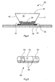
- FIG. 5 shows an embodiment of a cylindrically shaped position sensor 50 having a cavity 51 which is enclosed by a cylindrical wall 56.
- the cylinder wall 56 has two longitudinally spaced-apart electrically conductive ring contacts 54 and 52.
- the cavity 51 is partially filled with electrically conductive balls 58. If the cylindrical position sensor 50 is longitudinally axially in a horizontal orientation, the electrically conductive ring contacts 52 and 54 are electrically connected to one another by the electrically conductive balls 58.
- an angle to the horizontal can be set at which the ring contacts 52 and 54 are still - or no longer - electrically connected to each other.
- the electrically conductive ring contacts 52 and 54 are always electrically connected to each other when the carrier of the implantable medical Device is in a horizontal position, regardless of whether the wearer takes a supine, prone or lateral position.
- a position sensor there is an electrically conductive ball in a cavity, which is enclosed by a hollow spherical wall.
- On the inside of the hollow ball wall are a plurality of electrically conductive contacts.
- the ball diameter of the electrically conductive ball in the cavity and the distance of the electrically conductive contacts on the inside of the position sensor wall are dimensioned such that in any position of the position sensor, at least two of the electrically conductive contacts are connected to each other via the electrically conductive ball, when electrically conductive ball acts, for example, a weight.
Abstract
Description
Die Erfindung betrifft ein medizinisches Gerät zur Implantation in einen Körper, mit einer Stimulationseinheit, welche ausgebildet ist, in Abhängigkeit von einem Apnoe-Therapiesignal einen elektrischen Stimulationsimpuls zu erzeugen, einer Schlaf-Detektoreinheit mit mindestens einem Signaleingang, welche ausgebildet ist, in Abhängigkeit von mindestens einem Eingangssignal einen Schlafzustand des Körpers zu erkennen und ein Schlaf-Signal zu erzeugen, welches einem Schlaf-Erkennungsergebnis entspricht. Das medizinische Gerät zur Implantation in einen Körper, im Folgenden auch implantierbares medizinisches Gerät genannt, weist auch eine Apnoe-Detektoreinheit auf, welche ausgebildet ist, in Abhängigkeit von mindestens einem von dem Körper verursachten Körpersignal eine Schlaf-Apnoe zu erkennen und ein Apnoe-Signal zu erzeugen, welches einem Apnoe-Erkennungsergebnis entspricht. Das implantierbare medizinische Gerät weist auch eine Therapieeinheit auf, welche mit der Schlaf-Detektoreinheit und mit der Apnoe-Detektoreinheit mindestens mittelbar verbunden und ausgebildet ist, in Abhängigkeit von dem Apnoe-Signal und dem Schlaf-Signal mindestens ein Apnoe-Therapiesignal zu erzeugen, welches Therapieinformation wahlweise zur Prävention von Schlaf-Apnoe, zur Behandlung von Schlaf-Apnoe oder beidem repräsentiert und dieses an die Stimulationseinheit zu senden.The invention relates to a medical device for implantation in a body, with a stimulation unit which is designed to generate an electrical stimulation pulse in response to an apnea therapy signal, a sleep detector unit having at least one signal input, which is formed as a function of at least recognize an input signal a sleep state of the body and to generate a sleep signal corresponding to a sleep detection result. The medical device for implantation in a body, also referred to below as an implantable medical device, also has an apnea detector unit which is designed to recognize a sleep apnea as a function of at least one body signal caused by the body and an apnea signal which corresponds to an apnea recognition result. The implantable medical device also has a therapy unit, which is at least indirectly connected to the sleep detector unit and with the apnea detector unit and designed to generate at least one apnea therapy signal depending on the apnea signal and the sleep signal, which therapy information optionally for the prevention of sleep apnea, Treatment of sleep apnea or both represents and send this to the stimulation unit.
Ein solches System hat einen besonderen Vorteil für Patienten, bei denen bereits eine Herzschrittmacher-Implantation angezeigt ist. Ein solches System kann auch vorteilhaft sein für Patienten, welche unter Schlaf-Apnoe leiden, ohne dass andere Indikationen für eine Implantation vorliegen. Ein signifikanter Bevölkerungsanteil ist von Atmungsstörungen betroffen. Eine solche Atmungsstörung ist beispielsweise Schlaf-Apnoe, ein vorübergehendes Aussetzen der Atmung. Die häufigste Erscheinung ist die obstruktive Schlaf-Apnoe, von welcher näherungsweise 6% der männlichen Bevölkerung in einem Alter über 40 Jahren betroffen sind. Bei der obstruktiven Schlaf-Apnoe kollabieren die oberen Luftwege und verschließen, wodurch das Passieren von Atemluft verhindert wird. Dies kann wiederholt im Schlaf auftreten.Such a system has a particular advantage for patients in whom a pacemaker implantation is already indicated. Such a system may also be beneficial for patients suffering from sleep apnea without other indications for implantation. A significant proportion of the population is affected by respiratory disorders. Such a respiratory disorder is, for example, sleep apnea, a temporary respiratory failure. The most common manifestation is obstructive sleep apnea, which affects approximately 6% of the male population over the age of 40 years. In obstructive sleep apnea, the upper airways collapse and occlude, preventing the passage of breathing air. This can occur repeatedly during sleep.
Eine andere Erscheinungsform der Schlaf-Apnoe ist das zentrale Schlaf-Apnoe-Syndrom. Bei diesem Syndrom bleiben die Atemwege offen, aber die zentrale Kontrolle der Atemmuskulatur ist nachteilig beeinflusst. Während diese Form der Apnoe bei etwa 10 bis 20% von allen an Schlaf-Apnoe Leidenden beobachtet wird, hat sie ein großes Übergewicht bei Patienten mit Herzinsuffizienz. Solche Patienten haben auch die Cheyne-Stokes-Atmung, welche ein periodisches Abnehmen und Zunehmen der Atemamplitude ist, auch als Atemtiefe bezeichnet. Der Patient hat in diesem Fall Perioden geringerer Atemtiefe, das bedeutet, zentrale Apnoe, und Perioden gesteigerter Atemtiefe, auch als Hyperventilation bezeichnet. Von diesen Atemfehlfunktionen sind die Herzrate, die Hämodynamik und der Blutdruck beeinflusst. Beispielsweise können die Apnea-Perioden eine Zunahme der sympathischen Aktivität anregen, welche das Herz negativ beeinträchtigen kann. Das Zusammenwirken von Schlaf-Apnoe mit Herzinsuffizienz reduziert wesentlich die Lebensqualität und die Leistungsfähigkeit des Patienten. Daher ist es wesentlich, dass in solchen Fällen die Schlaf-Apnoe überwacht, identifiziert und behandelt wird.Another manifestation of sleep apnea is the central sleep apnea syndrome. In this syndrome, the airways remain open, but the central control of the respiratory muscles is adversely affected. While this form of apnea is observed in about 10 to 20% of all sleep apnea sufferers, it has a high preponderance in patients with heart failure. Such patients also have the Cheyne-Stokes respiration, which is a periodic decrease and increase in respiratory amplitude, also referred to as respiratory depth. The patient in this case has periods of lesser depth of breath, that is, central apnea, and periods of increased depth of breath, also referred to as hyperventilation. These respiratory dysfunctions affect heart rate, hemodynamics, and blood pressure. For example, the apnea periods may stimulate an increase in sympathetic activity, which may adversely affect the heart. The interaction of sleep apnea with heart failure significantly reduces the quality of life and the patient's performance. Therefore, it is essential that sleep apnea be monitored, identified and treated in such cases.
Im Allgemeinen erfordern Atemfehlfunktionen, wie beispielsweise die Schlaf-Apnoe, eine kontinuierliche Überwachung eines Patienten und wenn mögliche eine kontinuierliche Behandlung, eher als nur während eines Aufenthaltes in einer medizinischen Einrichtung. Um diese Fehlfunktion zu überwachen und zu behandeln, muss der Patient während des Schlafes zu Hause überwacht und behandelt werden. Geräte aus dem Stand der Technik schließen die Verwendung von extern angebrachten Atemsensoren und Atemmasken ein. Bei diesen Geräten wird die Schlaf-Apnoe durch künstliche Atemgeräte behandelt, welche die Atmung die kontrollieren und eine Einatmung und Ausatmung erzwingen. Tatsächlich bedeuten diese Geräte eine signifikante Einschränkung der Lebensqualität. Da diese Therapie von der Kooperation des Patienten abhängt, könnte die aufdringliche Natur dieses Gerätes seine laufende Verwendung verhindern.In general, respiratory dysfunctions, such as sleep apnea, require continuous monitoring of a patient and, if possible, continuous treatment, rather than just during a stay at a medical facility. To monitor and treat this malfunction, the patient must be monitored and treated at home during sleep. Prior art devices include the use of externally mounted respiratory sensors and respiratory masks. In these devices, sleep apnea is treated by artificial respirators that control breathing and force inhalation and exhalation. In fact, these devices significantly limit the quality of life. Since this therapy depends on patient cooperation, the intrusive nature of this device may prevent its ongoing use.
In dem Artikel "
Ende des Jahres 2003 hat das St. Jude Medical Center eine neue Studie zur Evaluierung einer Schrittmachertherapie für Schlaf-Apnoe veröffentlicht. Wie bei der Garrigue-Studie, war hier der Plan den Einfluss einer erhöhten Schrittmacherrate während einer Ruhe-Phase zu bewerten, aber die Studie ist offensichtlich auf Herzschrittmacher-Patienten mit diagnostizierter Schlaf-Apnoe beschränkt. Offensichtlich will die St. Jude-Studie einen geheimen Algorithmus zum Herunterladen in den Herzschrittmacher eines Patienten verwenden.At the end of 2003, the St. Jude Medical Center published a new study evaluating pacemaker therapy for sleep apnea. As with the Garrigue study, the plan was to evaluate the impact of increased pacing rate during a resting period, but the study is apparently limited to pacemaker patients diagnosed with sleep apnea. Obviously, the St. Jude study wants to use a secret algorithm to download into a patient's pacemaker.
Aus
Aus
In der Schrittmacher-Therapie ist die Verwendung des Herzschlagvolumens als Eingabeparameter zur Justierung oder Anpassung der Schrittmacher-Rate bekannt. Ein Atemvolumen-Wert wird aus der Frequenz und der relativen Amplitude eines Atem-Signals berechnet, welches aus einer Messung einer intrathorakalen Impedanz bestimmt werden kann. Offensichtlich verwendet der St. Jude-Algorithmus eine Tageszeit-Uhr, um die Schrittmacher-Therapie ein- und auszuschalten. Selbstverständlich kann ein Algorithmus, basierend auf dem Auslesen einer Tageszeit-Uhr Probleme bereiten, wenn der Patient beim Reisen Zeitzonen passiert, in Folge dessen Zeitwechsel eintreten (wie auch solche Zeitwechsel zur Gewinnung von Tageslichtzeit) und wenn der Patient Schlafrhythmusstörungen hat.In pacemaker therapy, the use of the heartbeat volume is known as an input parameter for adjusting or adjusting the pacing rate. A tidal volume value is calculated from the frequency and relative amplitude of a respiratory signal, which can be determined from a measurement of intrathoracic impedance. Obviously, the St. Jude algorithm uses a time of day clock to turn pacemaker therapy on and off. Of course, an algorithm based on reading a time of day clock can cause problems when the patient is traveling through time zones, as a result of which time changes occur (as well as such time changes to gain daylight time), and when the patient has sleep disturbances.
Es ist daher die Aufgabe der vorliegenden Erfindung, ein Gerät zur Behandlung von Schlaf-Apnoe mittels einer übersteuerten Erregung des Vorhofes eines Herzens mittels eines implantierten Herzschrittmachers anzugeben.It is therefore the object of the present invention to provide a device for the treatment of sleep apnea by means of an overdriven excitement of the atrium of a heart by means of an implanted cardiac pacemaker.
Diese Aufgabe wird durch die in Anspruch 1 angegebene Merkmale gelöst.This object is achieved by the features specified in claim 1.
In einer bevorzugten Ausführungsform enthält die Apnoe-Detektoreinheit einen Apnoe-Gewichtungs-Diskriminator mit mindestens einem Eingang für ein Körpersignal enthält. Der Apnoe-Gewichtungs-Diskriminator ist ausgebildet, gemäß einer vorbestimmten Apnoe-Gewichtungsfunktion das Körpersignal zu bewerten und ein eine Schlaf-Apnoe repräsentierendes Apnoe-Signal zu erzeugen.In a preferred embodiment, the apnea detector unit includes an apnea weighting discriminator having at least one input for a body signal. The apnea weighting discriminator is configured to evaluate the body signal according to a predetermined apnea weighting function and to generate an apnea signal representing a sleep apnea.
Die Schlaf-Detektoreinheit enthält bevorzugt einen Schlaf-Gewichtungs-Diskriminator mit mindestens einem Eingang für ein Eingangssignal, wobei der Schlaf-Gewichtungs-Diskriminator ausgebildet ist, gemäß einer vorbestimmten Schlaf-Gewichtungsfunktion das Eingangssignal zu bewerten und ein einen Schlafzustand repräsentierendes Schlaf-Signal zu erzeugen.The sleep detector unit preferably includes a sleep weighting discriminator having at least one input for an input signal, wherein the sleep weighting discriminator is configured to evaluate the input signal according to a predetermined sleep weighting function and generate a sleep signal representing a sleep state ,
Weiter bevorzugt enthält der Schlaf-Gewichtungs-Diskriminator und/oder der Apnoe-Gewichtungs-Diskriminator eine Fuzzy-Logik.More preferably, the sleep weighting discriminator and / or the apnea weighting discriminator includes fuzzy logic.
Das medizinische Gerät enthält bevorzugt eine Tageszeit-Uhr, welche mit der Schlaf-Detektoreinheit verbunden ist und somit als ein Eingangs-Parameter zur Entscheidung, ob ein Schlaf-Status besteht oder nicht, zur Verfügung steht.The medical device preferably includes a time of day clock associated with the sleep detector unit and thus available as an input parameter for deciding whether a sleep status exists or not.
In einer besonderen Ausführungsform weist das medizinische Gerät einen Welt-Zeitzonen-Detektor mit einem Satellitenempfänger auf, wobei der Welt-Zeitzonen-Detektor mit der Tageszeit-Uhr wirkverbunden und ausgebildet ist, Satellitensignale zu empfangen, durch Auswertung der Satellitensignale eine Position auf der Erde zu ermitteln und anhand der Position auf der Erde ein Welt-Zeitzonensignal zu erzeugen und dieses an die Tageszeit-Uhr zu senden, welche ausgebildet ist, die Tageszeit entsprechend zu korrigieren.In a particular embodiment, the medical device comprises a world time zone detector having a satellite receiver, the world time zone detector operably connected to the time of day clock and configured to receive satellite signals to position on the earth by evaluating the satellite signals determine and generate from the position on the earth a world time zone signal and send it to the time of day clock, which is adapted to correct the time of day accordingly.
Beispielsweise kann das Satellitenempfangssystem die Position in Form von Koordinaten bestimmen. Anhand der Koordinaten kann das Satellitenempfangssystem eine Zuordnung in eine Welt-Zeitzone treffen, in welcher sich der Träger des medizinischen Gerätes derzeit befindet. Das Satellitenempfangssystem ist bevorzugt mit der Tageszeit-Uhr verbunden und kann somit eine Korrektur der Tageszeit bewirken, wenn der Träger des medizinischen Gerätes sich in einer anderen Zeitzone befindet. Dadurch kann vorteilhaft auf einfache Weise sichergestellt werden, dass der Träger des medizinischen Geräts bei Reisen durch verschiedene Zeitzonen der Welt nicht zur falschen Zeit therapiert wird, sofern eine Therapie in Abhängigkeit von einer Tageszeit erfolgen soll. Bevorzugt enthält das Satellitenempfangssystem das aus dem Stand der Technik bekannte Global-Positioning-System (GPS).For example, the satellite receiving system can determine the position in the form of coordinates. Based on the coordinates, the satellite receiving system can make an assignment to a world time zone in which the wearer of the medical device is currently located. The satellite receiving system is preferably associated with the time of day clock and thus can effect a correction of the time of day when the wearer of the medical device is in a different time zone. As a result, it can advantageously be ensured in a simple manner that the wearer of the medical device is not treated at the wrong time when traveling through different time zones of the world, if therapy is to take place as a function of a time of day. Preferably, the satellite receiving system includes the Global Positioning System (GPS) known in the art.
Die Stimulationseinheit ist ausgebildet, einen elektrischen Stimulationsimpuls zu erzeugen, welcher geeignet ist, um ein Gewebe derart zu stimulieren, dass eine Depolarisationsschwelle für eine Muskelkontraktion überschritten wird.The stimulation unit is configured to generate an electrical stimulation pulse which is suitable for stimulating a tissue such that a depolarization threshold for muscle contraction is exceeded.
In einer Ausführungsform weist die Stimulationseinheit Atemmuskulatur-Stimulationseinheit auf, welche ausgebildet ist, einen elektrischen Stimulationsimpuls zur Stimulation des Zwerchfells oder der Thoraxmuskulatur zu erzeugen. In dieser Ausführungsform weist das implantierbare medizinische Gerät einen Ausgang zum Anschluss von Atemmuskulatur-Stimulationselektroden auf.In one embodiment, the stimulation unit comprises respiratory musculature stimulation unit which is designed to generate an electrical stimulation pulse for stimulation of the diaphragm or the thorax musculature. In this embodiment, the implantable medical device has an outlet for connecting respiratory muscle stimulation electrodes.
In einer bevorzugten Ausführungsform weist das implantierbare medizinische Gerät einen Herzschrittmacher oder Defibrillator auf. In dieser Ausführungsform kann die Therapieeinheit mit dem Herzschrittmacher oder Defibrillator verbunden sein und an diesen Stimulationsinformation enthaltende Therapiesignale senden. Der Herzschrittmacher ist somit ausführendes Mittel zur Therapierung von Schlaf-Apnoe.In a preferred embodiment, the implantable medical device comprises a pacemaker or defibrillator. In this embodiment, the therapy unit may be connected to the pacemaker or defibrillator and send therapeutic signals containing stimulation information thereto. The pacemaker is thus an executive agent for the treatment of sleep apnea.
Ein Ausführungsbeispiel für einen Aktivitätssensor ist ein Beschleunigungsaufnehmer oder eine Closed-Loop-Stimulation (CLS).An exemplary embodiment of an activity sensor is an accelerometer or closed loop stimulation (CLS).
Ein Ruhe- oder Lastzustand des Körpers wird bei einer Closed-Loop-Stimulation aus einem intrakardialen Impedanzsignal abgeleitet. Diese Technik ist in dem Artikel "
Das implantierbare medizinische Gerät weist in einer bevorzugten Ausführungsform einen Sensor zur Erfassung der intrakardialen Impedanz auf, welcher mit dem Schlafdetektor verbunden und ausgebildet ist, anhand der intrakardialen Impedanz ein Ruhen des Körpers zu erkennen und ein den Ruhezustand des Körpers repräsentierendes Ruhezustands-Signal zu erzeugen. Der Sensor zur Erfassung der intrakardialen Impedanz kann auch als Kontraktilitätssensor ausgebildet sein.The implantable medical device, in a preferred embodiment, has an intracardiac impedance sensor connected to the sleep detector and configured to detect resting of the body based on intracardiac impedance and to generate a resting state signal representative of the resting state of the body. The sensor for detecting the intracardiac impedance may also be designed as a contractility sensor.
Das medizinische Gerät kann bei Geräten mit CLS den intrakardialen Impedanzsensor der CLS vorteilhaft mitnutzen, um ein intrakardiales Impedanzsignal aus der CLS abzuzweigen.The device can advantageously use the CLS intracardiac impedance sensor on devices with CLS to divert an intracardiac impedance signal from the CLS.
Ein Beschleunigungsaufnehmer kann vorteilhaft als triaxialer Beschleunigungsaufnehmer ausgebildet sein, bei welchem die Richtungsachsen der erfassbaren Beschleunigungen ein Orthogonalsystem bilden und welcher mit dem Schlaf-Detektor wirkverbunden und ausgebildet ist, ein eine Beschleunigung repräsentierendes Beschleunigungs-Zeitsignal zu erzeugen.An acceleration sensor can advantageously be designed as a triaxial acceleration sensor in which the directional axes of the detectable accelerations form an orthogonal system and which is operatively connected to the sleep detector and designed to generate an acceleration time signal representing an acceleration.
Dadurch kann eine Körperbewegung derart ausgewertet werden, dass das implantierbare medizinische Gerät bei einer Auswertung der Zeitsignale des Beschleunigungsaufnehmers anhand bevorzugt auftretender Beschleunigungsrichtungen zwischen normalen Tagesbewegungsabläufen und beispielsweise Rollbewegungen während eines Schlafes unterscheiden kann.As a result, a body movement can be evaluated in such a way that the implantable medical device can distinguish between normal daily movement sequences and, for example, rolling movements during sleep when evaluating the time signals of the acceleration sensor on the basis of preferably occurring directions of acceleration.
Das implantierbare medizinische Gerät weist in dieser Ausführung bevorzugt einen Beschleunigungsmuster-Klassifizierer auf, welcher ausgebildet ist, anhand vorbestimmter Beschleunigungsmuster, welche jeweils für alle drei Bewegungsachsen abgespeichert sein können, Körperbewegungen während eines Schlafes von denen während eines Tagesablaufes zu unterscheiden.In this embodiment, the implantable medical device preferably has an acceleration pattern classifier, which is formed on the basis of predetermined acceleration patterns, which are in each case for all three axes of motion can be stored to distinguish body movements during sleep from those during a daily routine.
In dieser Ausführungsform ist der Beschleunigungsmuster-Klassifizierer ausgangsseitig mit der Schlaf-Detektoreinheit und eingangsseitig mit dem Beschleunigungsaufnehmer verbunden und ausgebildet, ein Beschleunigungs-Zeitsignal auszuwerten und vorbestimmte Beschleunigungsmuster in dem Beschleunigungs-Zeitsignal zu erkennen, diese zu klassifizieren und ein ein Beschleunigungsmuster repräsentierendes Beschleunigungsmuster-Signal zu erzeugen und dieses ausgangsseitig auszugeben.In this embodiment, the acceleration pattern classifier is connected on the output side to the sleep detector unit and input side to the accelerometer and configured to evaluate an acceleration time signal and to detect predetermined acceleration patterns in the acceleration time signal, classify them, and an acceleration pattern signal representing an acceleration pattern to generate and output this output side.
Alternativ zu einem Beschleunigungsaufnehmer kann das Medizinische Gerät auch einen Geschwindigkeitsaufnehmer aufweisen.As an alternative to an accelerometer, the medical device may also have a speed sensor.
Die zur Klassifizierung vorgesehenen Beschleunigungsmuster können Zeitsignale oder Leistungsspektren sein, im Falle der Leistungsspektren weist der Beschleunigungsmuster-Klassifizierer eingangsseitig einen FFT-Analysator (FFT: Fast-Fourier-Transformation) auf, welcher ausgebildet ist, aus einem Beschleunigungs-Zeitsignal kontinuierlich Beschleunigungsmuster-Leistungsspektren zu erzeugen und diese an den Beschleunigungsmuster-Klassifizierer zu senden. Die Abspeicherung von Leistungsspektren zum Klassifizierungsvergleich ist im Vergleich zur Abspeicherung von Zeitsignalen vorteilhaft besonders sparsam im Speicherplatzverbrauch.The acceleration patterns provided for classification may be time signals or power spectra, in the case of power spectra the acceleration pattern classifier has on the input side an FFT analyzer (FFT: Fast Fourier Transform), which is designed to continuously supply acceleration pattern power spectra from an acceleration time signal and send them to the accelerator pattern classifier. The storage of power spectra for classification comparison is advantageous in comparison to the storage of time signals particularly economical in storage space consumption.
In einer bevorzugten Ausführungsform weist das implantierbare medizinische Gerät eine Tageszeit-Uhr auf, welche mit der Schlaf-Detektoreinheit verbunden ist.In a preferred embodiment, the implantable medical device has a time of day clock which is connected to the sleep detector unit.
Weiter bevorzugt weist das implantierbare medizinische Gerät zusätzlich zur Tageszeit-Uhr mindestens einem Aktivitäts-Sensor auf, um die Genauigkeit der Erkennung zu steigern, ob ein Schlaf begonnen hat oder endet und ob eine Stimulationstherapie gestartet oder beendet werden sollte.More preferably, in addition to the time of day clock, the implantable medical device has at least one activity sensor to increase the accuracy of detection, whether sleep has begun or ended, and whether pacing therapy should be started or stopped.
Um den Stimulationsalgorithmus der vorliegenden Erfindung zu aktivieren, das bedeutet, das Stimulationsprotokoll auf "An" zu schalten, erfordert der Algorithmus, dass die Tageszeit-Uhr anzeigen muss, dass die Zeit in einem vorbestimmten Zeitintervall zum Schlafen liegt und dass mindestens ein Aktivitätssensor das Fehlen einer Bewegung des Patienten anzeigt.In order to activate the stimulation algorithm of the present invention, which means switching the stimulation protocol to "on", the algorithm requires that the time of day clock must indicate that the time is within a predetermined time interval for sleep and that at least one activity sensor is missing indicates a movement of the patient.
Ein ersichtliches Anliegen ist die Fähigkeit des Patienten, beim Einschalten des Stimulationsprotokolls einzuschlafen, welches auftreten kann, wenn das Protokoll durch die oben genannten Bedingungen aktiviert ist. Das Stimulationsprotokoll bedeutet in diesem Fall ein Ansteigen der Herzrate. Hierzu ist erfindungsgemäß eine Zunahme der Stimulationsrate mit einer ansteigenden Flanke über eine Periode von 10 Minuten vorgesehen. Die Gesamtzunahme der Stimulationsrate beträgt 10 Schläge pro Minute und wird durch einen Anstieg der Stimulationsrate von einem Schlag pro Minute über 10 Minuten erreicht.One apparent concern is the ability of the patient to fall asleep when the stimulation protocol is turned on, which may occur when the protocol is activated by the above conditions. The stimulation protocol in this case means an increase in the heart rate. For this purpose, an increase of the stimulation rate with a rising edge over a period of 10 minutes is provided according to the invention. The overall increase in pacing rate is 10 beats per minute and is achieved by increasing the pacing rate from one beats per minute to 10 minutes.
Der Schlafalgorithmus der vorliegenden Erfindung kann das Stimulationsprotokoll zu Aus" setzen, wenn das vorbestimmte Zeitintervall erreicht ist und eine Bewegung von mindestens einem Aktivitätssensor erkannt ist. Ebenso wie ein bevorzugter Schlafalgorithmus die Stimulationsrate gemäß eine Rampenfunktion beim Anschalten des Stimulationsprotokolls steigern kann, kann der bevorzugte Schlafalgorithmus die Stimulationsrate auch auf eine ähnliche absolute Rate absenken. Wenn zum Beispiel die Stimulationsrate beim Einschalten um einen Schlag pro Minute zunimmt, sollte die Abnahme auch einen Schlag pro Minute beim Beenden betragen.The sleep algorithm of the present invention may disable the pacing protocol when the predetermined time interval is reached and motion is detected by at least one activity sensor, just as a preferred sleep algorithm may increase the pacing rate in accordance with a ramping on pacing protocol, the preferred sleep algorithm may be Lower the stimulation rate to a similar absolute rate, for example, if the stimulation rate increases by one beat per minute at power up, the decrease should also be one beat per minute on exit.
Wenn mehr als nur ein Aktivitätssensor vorhanden ist, sind eine Vielzahl von Algorithmen zur Erkennung vorgesehen, ob ein "KEINE-BEWEGUNG-Status" erreicht ist. Andernfalls ist eine positive Erkennung des "KEINE-BEWEGUNG-Status" einer der vorgenannten Abfühlmittel ausreichend. In einem weiter bevorzugten dritten Algorithmus kann den verschiedenen Abfühlmitteln jeweils ein Gewichtungsfaktor und das Vorherrschen von "KEINE-BEWEGUNG" gewichteten Signalen zugewiesen werden, was ausreichend sein kann.If there is more than one activity sensor, a variety of algorithms are provided to detect if a "no-move status" has been reached. Otherwise, a positive detection of the "NO MOTION status" of one of the aforementioned sensing means is sufficient. In a further preferred third algorithm, the different sensing means may respectively a weighting factor and the prevalence of "NO MOTION" weighted signals can be assigned, which may be sufficient.
Bei jedem der Schlafalgorithmen der vorliegenden Erfindung ist die Möglichkeit, das Ansteigen/Abfallen der Stimulationsrate und die vorbestimmte Schlafzeitperiode extrakorporal zu programmieren, als wesentlich erachtet.In any of the sleep algorithms of the present invention, the ability to extracorporeally program the rate of increase / decrease of the stimulation rate and the predetermined period of sleep time is considered essential.
In einigen Ausführungsformen der vorliegenden Erfindung liest der Algorithmus auch das Atemmuster des Patienten über die Signalform der Minutenventilation oder die Closed-Loop-Stimulation (CLS) Signalform, um eine Schlaf-Apnoe zu erkennen. In dieser Ausführungsform kann eine Stimulation nur über die Erkennung einer Schlaf-Apnoe auf "An" geschaltet werden.In some embodiments of the present invention, the algorithm also reads the patient's breathing pattern via the Minute Ventilation waveform or the Closed Loop Stimulation (CLS) waveform to detect sleep apnea. In this embodiment, stimulation can only be switched to "on" via the recognition of a sleep apnea.
In einigen weiteren Ausführungsformen ist ein einfacher Positionsdetektor ausgebildet, wobei in diesem Fall der Status des Positionsdetektors in einem Teil des Schlafalgorithmus verwendet werden kann, um zu erkennen, ob ein Schlaf begonnen hat.In some other embodiments, a simple position detector is formed, in which case the status of the position detector may be used in a part of the sleep algorithm to detect if sleep has begun.
Ein implantierbares Monitoring-System der vorliegenden Erfindung überwältigt alle Grenzen bisher bekannter Systeme. Das System kann die Atmung überwachen und Atmungsinformationen mit anderen diagnostischen Daten zu einem Remote-Monitoring-Center senden. In dieser Weise ist ein Arzt in der Lage, den Patienten zu überwachen, ohne den Patienten kontinuierlich zu beobachten. Der Atmungsmonitor kann in ein therapeutisches Gerät integriert sein, welches ein implantierbarer Schrittmacher oder ein Defibrillator (ICD, ICD: Implantable Cardioverter/Defibrillator) ist, oder es kann als Stand-Alone diagnostisches Gerät arbeiten.An implantable monitoring system of the present invention overcomes all limits of previously known systems. The system can monitor respiration and send respiratory information with other diagnostic data to a remote monitoring center. In this way, a physician is able to monitor the patient without continuously monitoring the patient. The respiratory monitor may be integrated with a therapeutic device which is an implantable pacemaker or defibrillator (ICD, ICD: Implantable Cardioverter / Defibrillator) or it may operate as a stand-alone diagnostic device.
Die Atmung wird über die intrathorakale Impedanz gemessen.Breathing is measured via the intrathoracic impedance.
Eine Überwachung kann mit verschiedenen therapeutischen Mitteln kombiniert sein. Beispielsweise kann eine Schlaf-Apnoe-Therapie in eine Resynchronisations-Therapie unter Verwendung eines Herzschrittmachers oder Defibrillators (ICD) für Patienten mit Herzinsuffizienz eingebunden sein.Monitoring may be combined with various therapeutic agents. For example, sleep apnea therapy can be used in a resynchronization therapy using a cardiac pacemaker or defibrillator (ICD) for heart failure patients.
Der implantierbare Atmungsmonitor umfasst Mittel zur Messung der Impedanz, ein Mittel für eine Long-Distance-Telemetrie (LDT), Mittel zum Speichern von Daten, Mittel zum Messen eines Herzaktionssignales und eine zentrale Steuereinheit. Viele der Monitore können auch ein Elektrotherapeutisches Modul umfassen, wie einen Herzschrittmacher, einen Defibrillator (ICD) oder beides.The implantable respiratory monitor includes means for measuring impedance, a means for long distance telemetry (LDT), means for storing data, means for measuring a cardiac action signal, and a central control unit. Many of the monitors may also include an electrotherapeutic module, such as a pacemaker, a defibrillator (ICD), or both.
In einer Ausführungsform können die Mittel zur Messung der Impedanz einen unter-reizschwelligen elektrischen Strom zwischen zwei Elektroden, welche von den zur Verfügung stehenden Leitungen ausgewählt sind, injizieren. Der Strom kann aus biphasigen Pulsen mit konstanter Amplitude bestehen. Zur Messung einer Spannung kann ein Elektrodenpaar verwendet werden.In one embodiment, the means for measuring the impedance may inject a sub-threshold electrical current between two electrodes selected from the available leads. The current can consist of biphasic pulses with constant amplitude. To measure a voltage, a pair of electrodes can be used.
Die gemessene Spannung ist in diesem Fall proportional zur Impedanz des Gewebes in der Messregion. In einigen Ausführungsformen sind die Strom- und Spannungselektroden dieselben Elektroden. Vor einer Analog-DigitalWandlung wird die Spannung verstärkt und gefiltert. Eine Bandpassfilter ist hierfür bevorzugt. Der Filter kann so ausgewählt sein, dass das Atmungssignal passiert, aber höhere und niedrigere Frequenzkomponenten abgeschwächt sind.The measured voltage in this case is proportional to the impedance of the tissue in the measuring region. In some embodiments, the current and voltage electrodes are the same electrodes. Before an analog-digital conversion, the voltage is amplified and filtered. A bandpass filter is preferred for this purpose. The filter may be selected to pass the respiratory signal but attenuate higher and lower frequency components.
Das Medizinische Gerät weist bevorzugt einen Sauerstoffsensor auf, welcher mit der Apnoe-Detektoreinheit verbunden und ausgebildet ist, eine Sauerstoffkonzentration in Blut zu bestimmen und ein die Blut-Sauerstoffkonzentration repräsentierendes Blut-Sauerstoffsignal zu erzeugen. Die Sauerstoffkonzentration in Blut dient somit als Eingangsgröße für die Apnoe-Detektoreinheit.The medical device preferably comprises an oxygen sensor which is connected to the apnea detector unit and configured to determine an oxygen concentration in blood and to generate a blood oxygen signal representing the blood oxygen concentration. The oxygen concentration in blood thus serves as input for the apnea detector unit.
In einer Ausführungsform weist das implantierbare medizinisches Gerät eine Atemminutenvolumen-Erfassungseinheit auf, welche mit der Apnoe-Detektoreinheit verbunden ist. Bevorzugt enthält die Atemminutenvolumen-Erfassungseinheit Mittel zur Bestimmung der thorakalen Impedanz.In one embodiment, the implantable medical device has a respiratory minute volume detection unit associated with the apnea detector unit connected is. The respiratory minute volume acquisition unit preferably contains means for determining the thoracic impedance.
Um eine Atmung zu erkennen, muss die thorakale Impedanz ermittelt werden. Die Impedanz des Thorax verändert sich während der Atmungszyklen, weil die elektrische Leitfähigkeit der Lungen sich entsprechend einem unterschiedlichen Luftgehalt verändert. Die thorakale Impedanz ändert sich auch entsprechend geometrischen Unterschieden.To detect respiration, the thoracic impedance must be determined. The impedance of the thorax changes during the respiratory cycles because the electrical conductivity of the lungs changes according to a different air content. The thoracic impedance also changes according to geometric differences.
Eine bevorzugte Ausführung für einen Detektor der thorakalen Impedanz ist eine Tripolare-Messkonfiguration nutzt das Gehäuse oder die Dose des Implantats als gemeinsame Elektrode für Strom und Spannung. Zwischen der Dose und einer Ringelektrode der rechten ventrikulären Leitung oder der linken ventrikulären Leitung wird ein Strom injiziert. Die resultierende Spannung wird zwischen der Elektrodenspitze und der Dose gemessen, so dass gewissermaßen die Impedanz des thorakalen Gewebes gemessen wird. Auch eine Leitung zur Stimulation des linken Ventrikels, entweder eine Koronar-Sinus-Leitung oder Epikard-Leitungen können mit der entsprechenden tripolaren Konfiguration verwendet werden. In diesem Fall ist der linke Teil der Lunge in der Messregion enthalten. In einigen Ausführungsformen kann auch eine Defibrillatorleitung (ICD-Leitung), eingeschlossen der Erregungsspule, für Impedanzmessungen zum Einsatz kommen.A preferred embodiment for a thoracic impedance detector is a tripolar measurement configuration utilizing the housing or can of the implant as a common electrode for current and voltage. A current is injected between the can and a ring electrode of the right ventricular lead or the left ventricular lead. The resulting voltage is measured between the tip of the electrode and the can, so that, as it were, the impedance of the thoracic tissue is measured. Also a lead for stimulation of the left ventricle, either a coronary sinus lead or epicardial leads can be used with the appropriate tripolar configuration. In this case, the left part of the lung is included in the measurement region. In some embodiments, a defibrillator lead (ICD lead), including the excitation coil, may also be used for impedance measurements.
In einer Ausführungsform weist das Medizinische Gerät eine Herzschlagvolumen-Erfassungseinheit auf, welche mit der Schlaf-Detektoreinheit und/oder der Therapieeinheit verbunden und ausgebildet ist, ein Herzschlagvolumen zu bestimmen und ein das Herzschlagvolumen repräsentierendes Herzschlagvolumensignal zu erzeugen. Das Herzschlagvolumen kann somit als Eingangsgröße zur Schlaferkennung oder als Ist-Zustandsgröße für die Therapieeinheit zur Regelung des Herzschlagvolumens dienen.In one embodiment, the medical device has a heartbeat volume detection unit which is connected to the sleep detector unit and / or the therapy unit and configured to determine a heartbeat volume and to generate a heartbeat volume signal representing the heartbeat volume. The heartbeat volume can thus serve as an input to sleep detection or as an actual state variable for the therapy unit for regulating the heartbeat volume.
In einer bevorzugten Ausführungsform umfasst der Positionssensor wenigstens zwei Schaltkontakte und mindestens eine elektrisch leitfähige Kugel welche derart angeordnet ist, in Abhängigkeit von der Neigung des Positionssensors die Schaltkontakte elektrisch leitend zu verbinden oder zu trennen. Die elektrisch leitfähigen Kugeln sind bevorzugt Metallkugeln.In a preferred embodiment, the position sensor comprises at least two switching contacts and at least one electrically conductive ball which is arranged so as to electrically connect or disconnect the switching contacts depending on the inclination of the position sensor. The electrically conductive balls are preferably metal balls.
Alternativ dazu kann ein Positionssensor anstatt der Metallkugeln auch Kohlekugeln enthalten. Bevorzugt enthalten die Kohlekugeln komprimierten Aktivkohlestaub, weiter bevorzugt zusätzlich ein Bindemittel. Der Vorteil des Einsatzes der Aktivkohlekugeln besteht darin, dass die Zahl der am Kurzschluss beteiligten Kohlekugeln vom Positionswinkel des Positionssensors gegenüber der horizontalen abhängt. Dadurch ergibt sich in Abhängigkeit von der Winkellage ein unterschiedlicher elektrischer Widerstand zwischen den Kontakten des Positionssensors. Alternativ kann zur Erzielung der gleichen Wirkung wie die der Kohlekugeln auch ein Kugelmaterial mit einem vorbestimmten ohmschen Widerstand zum Einsatz kommen. Bevorzugt sind solche Kugeln Kunststoffkugeln oder Glaskugeln, welche mit einer dünnen Metallschicht bedampft sind. Die Leitfähigkeit der Metallschicht ist über die Schichtdicke und die texturellen Eigenschaften einstellbar.Alternatively, a position sensor may include carbon spheres instead of the metal spheres. Preferably, the carbon spheres contain compressed activated carbon dust, more preferably additionally a binder. The advantage of using the activated carbon spheres is that the number of carbon spheres involved in the short circuit depends on the positional angle of the position sensor relative to the horizontal one. This results in a function of the angular position, a different electrical resistance between the contacts of the position sensor. Alternatively, to achieve the same effect as that of the carbon spheres, a ball material having a predetermined ohmic resistance may also be used. Preferably, such balls are plastic balls or glass balls, which are vapor-deposited with a thin metal layer. The conductivity of the metal layer can be adjusted via the layer thickness and the textural properties.
Der Positionssensor kann auch eine Hallsonde sein, welche ausgebildet ist, in Abhängigkeit von ihrer Ausrichtung im Erdmagnetfeld eine Hallspannung zu erzeugen.The position sensor may also be a Hall probe, which is designed to generate a Hall voltage as a function of its orientation in the earth's magnetic field.
Alternativ zu dieser Ausführungsform des Positionssensors kann ein Positionssensor im Sinne der Erfindung auch ein aus dem Stand der Technik bekannter Quecksilberschalter sein.As an alternative to this embodiment of the position sensor, a position sensor according to the invention may also be a mercury switch known from the prior art.
Das Fernbeobachtungssystem, welches mit der vorliegenden Erfindung zum Einsatz kommen kann, ist aus dem Stand der Technik bekannt. Das Implantat kann diagnostische Daten über die Long-Distance-Telemetrie-Mittel (LDTM) zu einem Gerät außerhalb des Patienten senden, typischerweise ein Gerät, welches seitlich eines Patientenbettes positioniert ist. Von dort werden die Daten zu einem zentralen Service-Center gesendet, wo ein Arzt auf die Daten zugreifen kann.The remote viewing system which can be used with the present invention is well known in the art. The implant may send diagnostic data via the long-distance telemetry means (LDTM) to a device outside the patient, typically a device positioned laterally of a patient bed. From there, the data is sent to a central service center where a doctor can access the data.
Das Atmungssignal eines Patienten stellt viele Parameter bereit, welche für diagnostische Zwecke extrahiert werden können. Diese Daten sind in dem Implantat gespeichert und können in einer komprimierten Form gesendet werden. Die gespeicherten Werte können auch mit einem externen Gerät vom Arzt abgefragt werden. Das externe Gerät kann die empfangenen Daten auf einem Display in Form von Zahlen, Trends, Histogrammen oder vergleichbaren Anzeigen. Für ein Fernüberwachung werden die Daten in Langzeit-Mittelwerte, Zahlenwerte usw. komprimiert, welche beispielsweise alle 24h zu einem Service-Center oder einer Normal-Basis gesendet werden. Zusätzlich kann das Gerät derart ausgestattet sein, dass es dem Patienten erlaubt ist, eine Sendung zu veranlassen. Das beabsichtige erfindungsgemäße Gerät kann auch mit Schwellwertschaltern ausgestattet sein, basierend auf verschiedenen möglichen Alarmkriterien.The respiratory signal of a patient provides many parameters that can be extracted for diagnostic purposes. These data are stored in the implant and can be sent in a compressed form. The stored values can also be queried by an external device from the doctor. The external device can display the received data on a display in the form of numbers, trends, histograms or similar displays. For remote monitoring, the data is compressed into long-term averages, numerical values, etc., which are sent, for example, every 24 hours to a service center or a normal base. In addition, the device may be equipped to allow the patient to initiate a shipment. The intended device according to the invention may also be equipped with threshold switches based on various possible alarm criteria.
Verschiedene diagnostische Parameter können aus dem Atmungssignal extrahiert und als Apnoe-Statistikinformation abgespeichert werden. Das können die folgenden Parameter sein, ohne auf diese beschränkt zu sein:Various diagnostic parameters can be extracted from the respiratory signal and stored as apnea statistics information. These can be, but are not limited to, the following parameters:
Atmungsfrequenz; Atemminutenvolumen (relativ zu einem Referenzwert); Zählwert der Atempausen (oder der Apnoe-Ereignisse); Dauer der Atempausen; Zähler der Hyperventilationsphasen; Dauer der Hyperventilationsphasen; Klassifizierung der Atemphasen (normal, obstruktive Apnoe, Central-Apnoe, Hyperventilation, Cheyne-Stokes-Atmung). Eine Überwachung von Lungenödemen ist auch denkbar.Respiratory rate; Respiratory minute volume (relative to a reference value); Count of breathing pauses (or apnea events); Duration of breathing breaks; Counter of hyperventilation phases; Duration of hyperventilation phases; Classification of respiratory phases (normal, obstructive apnea, central apnea, hyperventilation, Cheyne-Stokes respiration). Monitoring of pulmonary edema is also conceivable.
Von dem Implantat erfasste Herzaktionssignale können auch mit den Atemsignalen korreliert werden. Das ist insbesondere wichtig für die Überwachung der zentralen Schlaf-Apnoe und für Patienten mit Herzinsuffizienz, welche an Schlaf-Apnoe leiden. Einige der Herzsignaldaten können die Herzrate, Ereigniszähler usw. enthalten, sind aber nicht auf diese beschränkt. Veränderungen der Herzrate können sich als besonders nützlich erweisen in Verbindung mit Atmungsdaten, seit bekannt ist, dass die obstruktive Schlaf-Apnoe häufig von alternierenden Phasen der Bradykardie und der Tachykardie begleitet ist. Die diagnostische Funktionalität des Implantats kann mit therapeutisches Optionen kombiniert sein, beispielsweise einer atrialen Überstimulation. Der Atmungssensor kann eine Schrittsteuerungstherapie auslösen, wenn eine Apnoe detektiert wurde.Cardiac action signals detected by the implant may also be correlated with the respiratory signals. This is particularly important for the monitoring of central sleep apnea and for patients with heart failure who suffer from sleep apnea. Some of the heart signal data may include, but is not limited to, the heart rate, event counters, etc. Changes in heart rate may prove particularly useful in conjunction with respiratory data since it has been known that obstructive sleep apnea is often accompanied by alternating phases of bradycardia and tachycardia. The diagnostic functionality of the implant may be combined with therapeutic options, such as atrial overstimulation. The respiratory sensor may trigger a pacing therapy when apnea has been detected.
Das Gerät kann auch als Therapiemonitor zum Einsatz kommen. Ein Langzeiterfolg oder kurzfristiger Erfolg der Schrittmachertherapie kann überwacht werden. Zusätzlich kann eine medikamentöse Therapie entsprechend einer Atemfehlfunktion in Verbindung mit dem Implantat zum Einsatz kommen.The device can also be used as a therapy monitor. A long-term success or short-term success of pacing therapy can be monitored. In addition, drug therapy corresponding to respiratory dysfunction associated with the implant may be used.
Die Erfindung soll nun anhand von Figuren näher erläutert werden:
-
Figur 1 zeigt - schematisch - eine Ausführungsform des implantierbaren medizinischen Gerätes, das Zusammenwirken seiner Merkmale und seine Wirkung mit Geräten in seiner Umgebung. -
Figur 2 zeigt -schematisch - Elemente der Schlaf-Detektoreinheit und der Apnoe-Detektoreinheit zusammen mit Sensoren in einem Signalverlaufsdiagramm.
-
FIG. 1 shows - schematically - an embodiment of the implantable medical device, the interaction of its features and its effect with devices in its environment. -
FIG. 2 Schematically shows elements of the sleep detector unit and the apnea detector unit together with sensors in a waveform diagram.
Die
Der Impedanzsensor 120 ist ausgebildet, zur Erfassung einer intrathorakalen Impedanz einen Strom zwischen dem Gehäuse des implantierbaren medizinischen Gerätes 101 und der Ringelektrode 134 fließen zu lassen und eine daraus resultierende Spannung zwischen dem Gehäuse und der Spitzenelektrode 136 zu erfassen. Dazu ist der Impedanzsensor 120 über eine Gehäuseleitung 169 mit dem Gehäuse des implantierbaren medizinischen Gerätes 101 verbunden und über eine Verbindungsleitung 168 mit der Schrittmacher-Einheit 118 verbunden, wobei die Schrittmacher-Einheit 118 ausgebildet ist, während einer Stimulationspause eine elektrische Verbindung zwischen dem Impendanzsensor 120 und der Ringelektrode 134 und der Spitzenelektrode 136 herzustellen, wenn die Elektrodenleitung 130 am Stimulationsausgang 131 des implantierbaren medizinischen Gerätes 101 angeschlossen ist.The
Die Apnoe-Detektoreinheit 114 ist über eine Verbindungsleitung 170 mit dem Impedanzsensor 120 verbunden und ausgebildet, den Zeitverlauf eines von dem Impedanzsensor 120 erfassten intrathorakalen Impedanzsignals auszuwerten und daraus ein Atmungssignal zu erzeugen, dieses Atmungssignal nach seinem Zeitverlauf auszuwerten und ein entsprechendes - beispielsweise Atempauseninformation enthaltendes - Auswertungsergebnis erzeugen.The
Als Ausgangssignal kann die Apnoe-Detektoreinheit 114 ein Apnoe-Detektorsignal erzeugen, welches das Auswertungsergebnis beispielsweise in Form einer Apnoe-Statusinformation und einer Apnoe-Therapieinformation repräsentiert und dieses an die zentrale Steuereinheit 110 senden. Dazu ist die Apnoe-Detektoreinheit 114 ausgangsseitig über eine Verbindungsleitung 172 mit der zentralen Steuereinheit 110 verbunden. Die Apnoe-Detektoreinheit 114 ist auch zur Übersendung von Apnoe-Statistikinformationen über eine Verbindungsleitung 171 mit der zentralen Steuereinheit 110 verbunden und dazu ausgebildet, ein statistisches Auswertungsergebnis des Atemsignals zu erzeugen und ein das Auswertungsergebnis repräsentierendes Apnoe-Statistiksignal über die Verbindungsleitung 171 an die zentrale Steuereinheit 110 zu senden.As an output signal, the
Das Apnoe-Statistiksignal kann die folgenden Parameter enthalten:
Die zentrale Steuereinheit 110 ist beispielsweise als programmierbarer Mikroprozessor ausgebildet und kann ein in dieser implementiertes Steuerprogramm ausführen.The
Die Schlaf-Detektoreinheit 112 ist ausgebildet, in Abhängigkeit von eingangsseitig über die Verbindungsleitungen 151, 158, 160, 162, und 176 Signale zu empfangen, diese auszuwerten, ein dem Auswertungsergebnis entsprechendes Schlaf-Signal zu erzeugen und dieses ausgangsseitig über die Verbindungsleitung 152 an die zentrale Steuereinheit 110 zu senden.The
Die Schlaf-Detektoreinheit 112 ist eingangsseitig über eine Herzraten-Verbindungsleitung 158 mit der Schrittmacher-Einheit 118 verbunden, welche ausgangsseitig ein einer erfassten Herzrate entsprechendes Herzratensignal erzeugt und dieses über die Verbindungsleitung 158 an die Schlaf-Detektoreinheit 112 senden kann.The
Die Schlaf-Detektoreinheit 112 ist eingangsseitig über eine Verbindungsleitung 160 mit einem Positionssensor 115 verbunden, welcher ausgebildet ist, in Abhängigkeit von seiner Winkellage im Verhältnis zur Horizontalen seinen elektrischen Widerstand zu ändern. Die Schlaf-Detektoreinheit 112 ist ausgebildet, die Winkellage des Positionssensor 115 abzufragen und dazu über die Verbindungsleitung 160 eine elektrische Spannung an den Positionssensor 115 anzulegen und einen resultierenden elektrischen Strom zu erfassen.The
Die Schlaf-Detektoreinheit 112 ist eingangsseitig über eine Verbindungsleitung 162 mit einem Beschleunigungsmuster-Klassifizierer 114 verbunden, welcher mit einem triaxialen Beschleunigungssensor 113 verbunden ist. Der Beschleunigungsmuster-Klassifizierer 114 ist ausgebildet, ein Zeitsignal des triaxialen Beschleunigungssensors 113 auszuwerten und zwischen verschiedenen Beschleunigungsmustern, welche Bewegungsmustern eines Trägers des implantierbaren medizinischen Gerätes 101 entsprechen, zu unterscheiden. Dazu ist der Beschleunigungsmuster-Klassifizierer 114 über eine Verbindungsleitung mit einer Beschleunigungsmuster-Speichereinheit 117 verbunden und ausgebildet, aus dieser dort abgespeicherte Beschleunigungsmuster auszulesen und mit den über den triaxialen Beschleunigungssensor 113 erfassten Beschleunigungsmustern zu vergleichen und die erfassten Beschleunigungsmuster zu klassifizieren. Der Beschleunigungsmuster-Klassifizierer 114 kann ein ein Beschleunigungsmuster repräsentierendes Beschleunigungsmuster-Signal erzeugen und dieses über die Verbindungsleitung 162 an die Schlaf-Detektoreinheit 112 senden.The
Der Beschleunigungsmuster-Klassifizierer 114 kann einen FFT-Analysator aufweisen, welcher ausgebildet ist, aus dem Zeitsignal des triaxialen Beschleunigungssensors 113 kontinuierlich eine Folge von Beschleunigungsmuster-Leistungsspektren zu erzeugen. Die Klassifizierung erfolgt dann anhand der Beschleunigungsmuster-Leistungsspektren und in der Beschleunigungsmuster-Speichereinheit 117 sind vorbestimmt Beschleunigungsmuster-Leistungsspektren abgelegt.The
Alternativ zu dieser Ausführungsform kann die Beschleunigungsmuster-Klassifikation auch anhand von Zeitsignalen erfolgen, was allerdings im Vergleich zu den Beschleunigungsmuster-Leistungsspektren deutlich mehr Speicherplatz erfordert.As an alternative to this embodiment, the acceleration pattern classification can also be performed on the basis of time signals, which, however, requires considerably more storage space than the acceleration pattern power spectra.
Die Schlaf-Detektoreinheit ist über eine Verbindungsleitung 176 mit einer Tageszeit-Uhr 122 verbunden, welche ausgebildet ist, ein einer Uhrzeit entsprechendes Tageszeit-Signal zu erzeugen und dieses ausgangsseitig über die Verbindungsleitung 176 an die Schlaf-Detektoreinheit zu senden. Die Tageszeit-Uhr ist über eine Verbindungsleitung 174 mit einem Welt-Zeitzonen-Detektor verbunden, welcher einen Satellitenempfänger, beispielsweise eine GPS-Empfänger aufweist.The sleep detector unit is connected via a connecting
Der Satellitenempfänger ist ausgebildet, ein von Satelliten 128 ausgesendetes Satellitensignal 129 zu empfangen, dieses auszuwerten und daraus eine Erdposition zu errechnen, beispielsweise in Form von Koordinaten. Der Welt-Zeitzonen-Detektor ist ausgebildet, beispielsweise mit einer Look-up-Tabelle eine ermittelte Erdposition einer Welt-Zeitzone zuzuordnen und ein Welt-Zeitzonensignal zu erzeugen und dieses ausgangsseitig über die Verbindungsleitung 174 an die Tageszeit-Uhr 122 zu senden.The satellite receiver is designed to receive a
Die zentrale Steuereinheit 110 ist über eine Verbindungsleitung 154 mit der Therapieeinheit 116 verbunden und kann je nach Erfordernis einer Therapie, gesteuert durch das Steuerprogramm in Abhängigkeit von dem über die Verbindungsleitung 172 empfangenen Apnoe-Detektorsignal und dem über die Verbindungsleitung 152 empfangenen Schlaf-Signal ein eine Therapieinformation enthaltendes Therapiesignal erzeugen und dieses Therapiesignal über die Verbindungsleitung 154 an die Therapieeinheit 116 senden. Die Therapieeinheit 116 ist über eine Verbindungsleitung 156 mit der Schrittmacher-Einheit 118 verbunden und ausgebildet, je nach von der zentralen Steuereinheit über die Verbindungsleitung 154 angeforderter Therapie aufgrund des Therapiesignals ein Herzraten-Anforderungssignal zu erzeugen und dieses über die Verbindungsleitung 156 an die Schrittmacher-Einheit 118 zu senden, welche daraufhin die Schrittrate entsprechend einstellen kann.The
Die zentrale Steuereinheit 110 ist zur Speicherung von beispielsweise über die Verbindungsleitung 171 empfangenen Apnoe-Statistikinformationen über eine Verbindungsleitung 178 mit einer Speichereinheit 124 verbunden.The
Die zentrale Steuereinheit 110 ist über einen bidirektionalen Datenbus 150 mit einer Telemetrieeinheit zur drahtlosen Datenübertragung (Long-Distance-Telemetrie-System) 128 verbunden. Beispielsweise ist die Telemetrieeinheit 128 eine Bluetooth-Telemetrieeinheit.The
Die zentrale Steuereinheit 110 kann somit Apnoe-Statistikinformation sowie von der Schrittmacher-Einheit 118 erfasste Herzsignalinformation 182 über die Telemetrieeinheit 128 schnurlos an ein mobiles Patienten-Applikationsgerät 137 senden. Über die Telemetrieeinheit 128 kann ein Steuerprogramm empfangen und über den bidirektionalen Datenbus 150 an die zentrale Steuereinheit 110 gesendet und dort abgelegt werden, die zentrale Steuereinheit 110 und die Telemetrieeinheit 128 können dazu entsprechend ausgebildet sein.The
Das mobile Patienten-Applikationsgerät 137 kann beispielsweise in der Nähe eines Patientenbettes aufgestellt sein. Das mobile Patienten-Applikationsgerät 137 ist zur Datenübertragung patientenbezogener Daten über eine Netzwerkverbindungsleitung 180 mit einem zentralen Servicecenter 138 verbunden. Von dort kann ein Arzt beispielsweise Patienteninformationen abrufen und überwachen. Alternativ zur Netzwerkverbindungsleitung 180 kann das mobile Patientenapplikationsgerät 137 und das zentrale Servicecenter 138 eine schnurlose Schnittstelle aufweisen, beispielsweise eine Bluetooth-Schnittstelle, und über diese Bluetooth-Schnittstelle schnurlos patientenbezogene Daten übertragen.For example, the mobile
Der Schlaf-Gewichtungs-Diskriminator 210 weist Signaleingänge auf, an welche über Verbindungsleitungen 270, 272, 274, 276 und 278 Sensoren beziehungsweise im weiteren Sinne Signalerzeuger angeschlossen sind. Der Schlaf-Gewichtungs-Diskriminator 210 ist ausgebildet, gemäß einer vorbestimmten Gewichtungsfunktion die an den Signaleingängen anliegenden Signale zu bewerten und ein das Bewertungsergebnis repräsentierendes Schlaf-signal zu erzeugen und dieses ausgangsseitig über eine Verbindungsleitung 256 an einen Therapie-Diskriminator 214 zu senden.The
Der Apnoe-Gewichtungs-Diskriminator 212 weist auch Signaleingänge auf, welche über Verbindungsleitungen 260, 262, 264 und 268 mit Signalerzeugern verbunden sind. Der Apnoe-Gewichtungs-Diskriminator 212 bewertet die an den Signaleingängen anliegenden Signale gemäß einer vorbestimmten Gewichtungsfunktion und erzeugt ein Apnoe-Signal und sendet dies ausgangsseitig über eine angeschlossene Verbindungsleitung 254 an den Therapie-Diskriminator 214.The
Der Schlaf-Gewichtungs-Diskriminator 210 ist über eine Verbindungsleitung 270 mit einem Herzratensensor 234 verbunden, welcher in der Schrittmacher-Einheit 118 enthalten sein kann. Über die Verbindungsleitung 270 kann somit eine Ist-Zustands-Herzrate von dem Herzratensensor 234 ausgesendet und von dem Schlaf-Gewichtungs-Diskriminator 210 empfangen werden. Der Schlaf-Gewichtungs-Diskriminator 210 ist über eine Verbindungsleitung 272 eingangsseitig mit einem Impedanzsensor 216 verbunden. Der Impedanzsensor 216 ist über eine Verbindungsleitung 241 mit einer Ringelektrode 240 und über eine Verbindungsleitung 239 mit einer Spitzenelektrode 238 verbunden, welche im Bereich des distalen Endes 242 einer Elektrodenleitung angeordnet sind.The
Der Impedanzsensor 216 ist auch über eine Verbindungsleitung 237 mit einem Gehäuse 236 des implantierbaren medizinischen Gerätes 101 verbunden und ausgebildet, ausgangsseitig über die Verbindungsleitungen 237 und 241 einen Strom fließen zu lassen und eingangsseitig über die Verbindungsleitung 239 und die Verbindungsleitung 237 eine resultierende Spannung zu erfassen und aus der erfassten Spannung und dem Strom eine Impedanz zu bilden. Der Impedanzsensor 216 ist ausgebildet, aus dieser erfassten Impedanz eine intrakardiale Impedanz zu errechnen und ein die intrakardiale Impedanz repräsentierendes Ausgangssignal über die Verbindungsleitung 272 an den Schlaf-Gewichtungs-Diskriminator 210 zu senden.The
Ein bereits in
Der Schlaf-Gewichtungs-Diskriminator 210 ist auch über eine Verbindungsleitung 276 eingangsseitig mit einem - wie in
Eine Tageszeit-Uhr 122 ist mit einem Welt-Zeitzonen-Detektor 126 eingangsseitig verbunden und ist ausgebildet, ein entsprechend einen Welt-Aufenthaltsort korrigiertes Uhrzeitsignal ausgangsseitig über eine Verbindungsleitung 278 an den Schlaf-Gewichtungs-Diskriminator 210 zu senden.A time-of-
Der Apnoe-Gewichtungs-Diskriminator ist über eine Verbindungsleitung 260 eingangsseitig mit einem Blut-Sauerstoffsensor 222 verbunden, über eine Verbindungsleitung 262 eingangsseitig mit einer Atemminutenvolumen-Erfassungseinheit 220 verbunden und über eine Verbindungsleitung 264 eingangsseitig mit einer Impedanz-Auswerteeinheit 218 verbunden.The apnea weighting discriminator is connected on the input side to a
Die Impedanz-Auswerteeinheit 218 ist über eine Verbindungsleitung 250 mit dem Impedanzsensor 216 verbunden und ausgebildet, ein eine Atmungsaktivität charakterisierendes Impedanz-Zeitsignal des Impedanzsensors 216 auszuwerten und ein die Anzahl und Dauer von Atempausen charakterisierendes Atemsignal zu erzeugen und dieses ausgangsseitig über die Verbindungsleitung 264 an den Apnoe-Gewichtungs-Diskriminator 212 zu senden.
Der Apnoe-Gewichtungs-Diskriminator 212 ist über eine Verbindungsleitung 268 eingangsseitig mit dem Herzratensensor 234 verbunden und kann somit ein von diesem erzeugten Herzratensignal als Eingangsgröße empfangen.The
The
Der Apnoe-Gewichtungs-Diskriminator ist ausgebildet, anhand einer vorbestimmten Apnoe-Gewichtungsfunktion ein Apnoe-Signal zu erzeugen und dies ausgangsseitig über die Verbindungsleitung 254 an den Therapie-Diskriminator 214 zu senden.The apnea weighting discriminator is designed to generate an apnea signal on the basis of a predetermined apnea weighting function and to send this on the output side via the
Der Therapie-Diskriminator bewertet anhand einer Therapie-Gewichtungsfunktion das eingangsseitig zur Verfügung stehende Apnoe-Signal und das eingangsseitig zur Verfügung stehende Schlaf-Signal und ordnet dem Bewertungsergebnis ein Therapieergebnis zu, welches von dem Therapiediskriminator ausgangsseitig über die Verbindungsleitung 258 an einem Diskriminator-Ausgang 213 ausgegeben werden kann. An den Diskriminator-Ausgang 213 kann die in
Wie in
Ist ein solcher zylinderförmiger Positionssensor 50 Bestandteil eines implantierbaren medizinischen Gerätes und ist die Längsachse des zylindrischen Positionssensors 50 parallel zur Körperlängsachse eines Trägers des implantierbaren medizinischen Gerätes ausgerichtet, so sind die elektrisch leitfähigen Ringkontakte 52 und 54 stets miteinander elektrisch verbunden, wenn der Träger des implantierbaren medizinischen Gerätes sich in einer horizontalen Position befindet, unabhängig davon, ob der Träger eine Rückenlage, Bauchlage oder Seitenlage einnimmt.If such a cylindrical position sensor 50 is part of an implantable medical device and the longitudinal axis of the cylindrical position sensor 50 is aligned parallel to the body longitudinal axis of a support of the implantable medical device, the electrically
In einer nicht dargestellten Ausführungsform eines Positionssensors befindet sich eine elektrisch leitfähige Kugel in einem Hohlraum, welcher von einer Hohlkugelwand umschlossen ist. An der Innenseite der Hohlkugelwand befinden sich eine Vielzahl elektrisch leitfähiger Kontakte. Der Kugeldurchmesser der elektrisch leitfähigen Kugel in dem Hohlraum und der Abstand der elektrisch leitfähigen Kontakte auf der Innenseite der Positionssensorwand sind derart bemessen, dass in jeder beliebigen Lage des Positionssensors mindestens zwei der elektrisch leitfähigen Kontakte über die elektrisch leitfähige Kugel miteinander verbunden sind, wenn auf die elektrisch leitfähige Kugel beispielsweise eine Gewichtskraft wirkt.In an embodiment of a position sensor, not shown, there is an electrically conductive ball in a cavity, which is enclosed by a hollow spherical wall. On the inside of the hollow ball wall are a plurality of electrically conductive contacts. The ball diameter of the electrically conductive ball in the cavity and the distance of the electrically conductive contacts on the inside of the position sensor wall are dimensioned such that in any position of the position sensor, at least two of the electrically conductive contacts are connected to each other via the electrically conductive ball, when electrically conductive ball acts, for example, a weight.
Claims (18)
- A medical device (101) for implantation in a body, having
a stimulation unit (118), which is implemented to generate an electrical stimulation pulse as a function of an apnea treatment signal,
a sleep detector unit (112) having at least one signal input, which is implemented to recognize a sleep status of the body as a function of at least one input signal and generate a sleep signal, which corresponds to a sleep recognition result,
an apnea detector unit (114), which is implemented to recognize sleep apnea as a function of at least one body signal caused by the body and generate an apnea signal which corresponds to an apnea recognition result,
a treatment unit (116), which is connected at least indirectly to the stimulation unit (118), the sleep detector unit (112), and the apnea detector unit (114), and is implemented to generate at least one apnea treatment signal as a function of the apnea signal and the sleep signal, which represents treatment information for preventing and/or treating sleep apnea, and to transmit it to the stimulation unit (118),
characterized in that the medical device has a position sensor (10, 30, 50, 115), which is operationally linked to the signal input of the sleep detector unit (112) and is implemented to change at least one of its electrical properties as a function of its inclination around at least one spatial axis running through the position sensor (10, 30, 50, 115) in relation to the horizontal,
the treatment unit (116) being implemented to generate the apnea treatment signal in the form of an increase of the stimulation rate having a rising flank over a period of 10 minutes in such a way that a total increase of the stimulation rate of 10 beats per minute results through a rise of the stimulation rate of one beat per minute over 10 minutes. - The medical device according to Claim 1, characterized in that the apnea detector unit (114) contains an apnea weighting discriminator (212) having at least one input for a body signal, the apnea weighting discriminator (212) being implemented to evaluate the body signal according to a predetermined apnea weighting function and to generate an apnea signal representing sleep apnea.
- The medical device according to one of the preceding claims, characterized in that the sleep detector unit (112) contains a sleep weighting discriminator (210) having at least one input for an input signal, the sleep weighting discriminator (210) being implemented to evaluate the input signal according to a predetermined sleep weighting function and to generate a sleep signal representing a sleep status.
- The medical device according to one of the preceding claims, characterized in that the medical device has a sensor for detecting the intracardial impedance (216), which is connected to the sleep detector and is implemented to recognize resting of the body on the basis of the intracardial impedance and to generate a rest status signal representing the rest status of the body.
- The medical device according to one of the preceding claims, characterized in that the medical device has a respiratory minute volume detection unit (220), which is connected to the apnea detector unit (114).
- The medical device according to one of the preceding claims, characterized in that the medical device has an oxygen sensor (222), which is connected to the apnea detector unit (114) and is implemented to determine an oxygen concentration in the blood and to generate a blood oxygen signal representing the blood oxygen concentration.
- The medical device according to one of the preceding claims, characterized in that the medical device has a heartbeat volume detection unit, which is connected to the sleep detector unit and/or the treatment unit and is implemented to determine a heartbeat volume and to generate a heartbeat volume signal representing the heartbeat volume.
- The medical device according to one of the preceding claims, characterized in that the medical device has a time of day clock (122), which is connected to the sleep detector unit (112) and is implemented to generate a time of day signal and transmit it to the sleep detector unit (112).
- The medical device according to Claim 8, characterized in that the medical device has a world time zone detector (126) having a satellite receiver, the world time zone detector (126) being operationally linked to the time of day clock (122) and being implemented to receive satellite signals (129), to ascertain a position on the Earth by analyzing the satellite signals (129), and to generate a world time zone signal on the basis of the position on the earth and transmit it to the time of day clock (122), which is implemented to correct the time of day accordingly.
- The medical device according to one of the preceding claims, characterized in that the medical device has a triaxial acceleration pickup (113), in which the directional axes of the detectable accelerations form an orthogonal system and which is operationally linked to the sleep detector unit (112) and is implemented to generate an acceleration time signal representing an acceleration.
- The medical device according to Claim 10, characterized in that the medical device has an acceleration pattern classifier (114), which is connected at its output to the sleep detector unit (112) and at its input to the acceleration pickup (113) and is implemented to analyze an acceleration time signal and recognize predetermined acceleration patterns in the acceleration time signal, classify them, and generate an acceleration pattern signal representing an acceleration signal and output it.
- The medical device according to Claim 11, characterized in that the acceleration pattern classifier (114) has an FFT analyzer at its input, which is implemented to generate acceleration pattern performance spectra continuously from an acceleration time signal and transmit them to the acceleration pattern classifier.
- The medical device according to one of the preceding claims, characterized in that the position sensor (10, 30, 50, 115) comprises at least two switch contacts and at least one electrically conductive ball, which is situated in such a way that it electrically connects or disconnects the switch contacts as a function of the inclination of the position sensor.
- The medical device according to one of Claims 1 through 12, characterized in that the position sensor (115) is a Hall probe, which is implemented to generate a Hall voltage as a function of its orientation in the Earth's magnetic field.
- The medical device according to one of the preceding claims, characterized in that the stimulation unit is a cardiac pacemaker or defibrillator.
- The medical device according to one of the preceding claims, characterized in that the stimulation unit is a respiration musculature stimulation unit, which is implemented to generate an electrical stimulation pulse for stimulating the diaphragm or the thorax musculature.
- A home monitoring system having an implantable medical device (101) according to one of Claims 1 through 17 and a mobile patient application device (137), the mobile patient application device (137) being wirelessly connected via a telemetry unit (128) to the implantable medical device (101).
- A patient monitoring system having an implantable medical device (101) according to one of Claims 1 through 17 and a mobile patient application device (137), which is wirelessly connectable to the implantable medical device (101) via a telemetry unit (128), and a central service center (138), the central service center (138) being at least temporarily connected via a network connection line (180) or a wireless connection line to the mobile patient application device (137) for data transmission of patient-related data.
Applications Claiming Priority (4)
| Application Number | Priority Date | Filing Date | Title |
|---|---|---|---|
| US49963103P | 2003-09-02 | 2003-09-02 | |
| US499631P | 2003-09-02 | ||
| DE10347294 | 2003-10-02 | ||
| DE10347294A DE10347294A1 (en) | 2003-10-02 | 2003-10-02 | Implantable medical apparatus with electrical stimulation unit, e.g. responding to sleep apnea, has position sensor connected with signal input of sleep detector unit to modify operation according to inclination |
Publications (2)
| Publication Number | Publication Date |
|---|---|
| EP1512430A1 EP1512430A1 (en) | 2005-03-09 |
| EP1512430B1 true EP1512430B1 (en) | 2008-02-13 |
Family
ID=34137329
Family Applications (1)
| Application Number | Title | Priority Date | Filing Date |
|---|---|---|---|
| EP04090229A Not-in-force EP1512430B1 (en) | 2003-09-02 | 2004-06-10 | Device for sleep-apnea treatment |
Country Status (4)
| Country | Link |
|---|---|
| US (1) | US7473227B2 (en) |
| EP (1) | EP1512430B1 (en) |
| AT (1) | ATE385830T1 (en) |
| DE (1) | DE502004006169D1 (en) |
Families Citing this family (58)
| Publication number | Priority date | Publication date | Assignee | Title |
|---|---|---|---|---|
| US8140164B2 (en) * | 2003-10-15 | 2012-03-20 | Rmx, Llc | Therapeutic diaphragm stimulation device and method |
| US9259573B2 (en) * | 2003-10-15 | 2016-02-16 | Rmx, Llc | Device and method for manipulating exhalation |
| US20060167523A1 (en) * | 2003-10-15 | 2006-07-27 | Tehrani Amir J | Device and method for improving upper airway functionality |
| US8265759B2 (en) * | 2003-10-15 | 2012-09-11 | Rmx, Llc | Device and method for treating disorders of the cardiovascular system or heart |
| US8467876B2 (en) * | 2003-10-15 | 2013-06-18 | Rmx, Llc | Breathing disorder detection and therapy delivery device and method |
| US7970475B2 (en) * | 2003-10-15 | 2011-06-28 | Rmx, Llc | Device and method for biasing lung volume |
| US8160711B2 (en) * | 2003-10-15 | 2012-04-17 | Rmx, Llc | Multimode device and method for controlling breathing |
| US8244358B2 (en) * | 2003-10-15 | 2012-08-14 | Rmx, Llc | Device and method for treating obstructive sleep apnea |
| US20080161878A1 (en) * | 2003-10-15 | 2008-07-03 | Tehrani Amir J | Device and method to for independently stimulating hemidiaphragms |
| US7979128B2 (en) * | 2003-10-15 | 2011-07-12 | Rmx, Llc | Device and method for gradually controlling breathing |
| TWI250326B (en) * | 2003-11-28 | 2006-03-01 | Prime Optical Fiber Corp | Optical fiber inclinometer |
| US7524279B2 (en) * | 2003-12-31 | 2009-04-28 | Raphael Auphan | Sleep and environment control method and system |
| US7387608B2 (en) | 2004-04-06 | 2008-06-17 | David A Dunlop | Apparatus and method for the treatment of sleep related disorders |
| WO2006052765A2 (en) | 2004-11-04 | 2006-05-18 | Smith & Nephew, Inc. | Cycle and load measurement device |
| JP2006204742A (en) * | 2005-01-31 | 2006-08-10 | Konica Minolta Sensing Inc | Method and system for evaluating sleep, its operation program, pulse oxymeter, and system for supporting sleep |
| US7269459B1 (en) * | 2005-02-08 | 2007-09-11 | Pacesetter, Inc. | Implantable cardiac device with selectable tiered sleep apnea therapies and method |
| US7644714B2 (en) | 2005-05-27 | 2010-01-12 | Apnex Medical, Inc. | Devices and methods for treating sleep disorders |
| US20070027367A1 (en) * | 2005-08-01 | 2007-02-01 | Microsoft Corporation | Mobile, personal, and non-intrusive health monitoring and analysis system |
| WO2007025191A1 (en) * | 2005-08-23 | 2007-03-01 | Smith & Nephew, Inc. | Telemetric orthopaedic implant |
| US20070233204A1 (en) | 2006-02-16 | 2007-10-04 | Lima Marcelo G | RFID-based apparatus, system, and method for therapeutic treatment of a patient |
| US9849216B2 (en) * | 2006-03-03 | 2017-12-26 | Smith & Nephew, Inc. | Systems and methods for delivering a medicament |
| US9744354B2 (en) * | 2008-12-31 | 2017-08-29 | Cyberonics, Inc. | Obstructive sleep apnea treatment devices, systems and methods |
| US9913982B2 (en) | 2011-01-28 | 2018-03-13 | Cyberonics, Inc. | Obstructive sleep apnea treatment devices, systems and methods |
| US8855771B2 (en) | 2011-01-28 | 2014-10-07 | Cyberonics, Inc. | Screening devices and methods for obstructive sleep apnea therapy |
| US9186511B2 (en) | 2006-10-13 | 2015-11-17 | Cyberonics, Inc. | Obstructive sleep apnea treatment devices, systems and methods |
| EP3527255B1 (en) | 2006-10-13 | 2020-08-05 | Cyberonics, Inc. | Obstructive sleep apnea treatment devices and systems |
| US9205262B2 (en) | 2011-05-12 | 2015-12-08 | Cyberonics, Inc. | Devices and methods for sleep apnea treatment |
| US8280513B2 (en) * | 2006-12-22 | 2012-10-02 | Rmx, Llc | Device and method to treat flow limitations |
| US7894890B2 (en) * | 2007-02-09 | 2011-02-22 | Neuropace, Inc. | Devices and methods for monitoring physiological information relating to sleep with an implantable device |
| US9445720B2 (en) | 2007-02-23 | 2016-09-20 | Smith & Nephew, Inc. | Processing sensed accelerometer data for determination of bone healing |
| US8570187B2 (en) * | 2007-09-06 | 2013-10-29 | Smith & Nephew, Inc. | System and method for communicating with a telemetric implant |
| US20170188940A9 (en) | 2007-11-26 | 2017-07-06 | Whispersom Corporation | Device to detect and treat Apneas and Hypopnea |
| AU2009209045B2 (en) * | 2008-02-01 | 2014-09-18 | Smith & Nephew, Inc. | System and method for communicating with an implant |
| JP5518053B2 (en) | 2008-05-15 | 2014-06-11 | インスパイア・メディカル・システムズ・インコーポレイテッド | Method and apparatus for detecting respiratory pressure in an implantable stimulation system |
| WO2010039853A1 (en) | 2008-10-01 | 2010-04-08 | Inspire Medical Systems, Inc. | Transvenous method of treating sleep apnea |
| AU2009302591B2 (en) | 2008-10-09 | 2014-08-07 | Imthera Medical, Inc. | Method of stimulating a hypoglossal nerve for controlling the position of a patient's tongue |
| RU2545424C2 (en) | 2008-10-15 | 2015-03-27 | Смит Энд Нефью, Инк. | Composite inner retainer |
| EP3184045B1 (en) | 2008-11-19 | 2023-12-06 | Inspire Medical Systems, Inc. | System treating sleep disordered breathing |
| EP2416845B1 (en) | 2009-03-31 | 2015-03-18 | Inspire Medical Systems, Inc. | Percutaneous access for systems of treating sleep-related disordered breathing |
| WO2011059531A1 (en) | 2009-11-10 | 2011-05-19 | Imthera Medical, Inc. | System for stimulating a hypoglossal nerve for controlling the position of a patient's tongue |
| EP2543027B1 (en) * | 2009-12-31 | 2016-08-24 | Nightbalance B.V. | Device for monitoring sleep position |
| CA2788510A1 (en) * | 2010-02-02 | 2011-08-11 | Nellcor Puritan Bennett Llc | System and method for diagnosing sleep apnea based on results of multiple approaches to sleep apnea identification |
| US8983572B2 (en) | 2010-10-29 | 2015-03-17 | Inspire Medical Systems, Inc. | System and method for patient selection in treating sleep disordered breathing |
| JP6092212B2 (en) | 2011-08-11 | 2017-03-08 | インスパイア・メディカル・システムズ・インコーポレイテッドInspire Medical Systems, Inc. | System for selecting a stimulation protocol based on detection results of respiratory effort |
| US8934992B2 (en) | 2011-09-01 | 2015-01-13 | Inspire Medical Systems, Inc. | Nerve cuff |
| EP2806932B1 (en) * | 2012-01-27 | 2018-10-31 | ResMed Limited | Discrimination of cheyne-stokes breathing patterns |
| EP4241662A1 (en) | 2014-02-11 | 2023-09-13 | Cyberonics, Inc. | Systems for detecting and treating obstructive sleep apnea |
| WO2016033245A1 (en) | 2014-08-26 | 2016-03-03 | Rmx, Llc | Devices and methods for reducing intrathoracic pressure |
| JP6759227B2 (en) | 2015-03-19 | 2020-09-23 | インスパイア・メディカル・システムズ・インコーポレイテッドInspire Medical Systems, Inc. | Stimulation to treat obstructive sleep apnea |
| US10729352B2 (en) | 2015-08-17 | 2020-08-04 | Neuropace, Inc. | Neurological event detection tools for implantable medical devices |
| EP3445444A1 (en) | 2016-04-19 | 2019-02-27 | Inspire Medical Systems, Inc. | Accelerometer-based sensing for sleep disordered breathing (sdb) care |
| CA3043325A1 (en) | 2016-11-10 | 2018-05-17 | The Research Foundation For The State University Of New York | System, method and biomarkers for airway obstruction |
| AU2018316277B2 (en) | 2017-08-11 | 2023-12-07 | Inspire Medical Systems, Inc. | Cuff electrode |
| EP3801744A4 (en) | 2018-06-01 | 2022-03-16 | Zennea Technologies Inc. | Method and device for treating sleep related breathing disorders |
| US20200281522A1 (en) | 2019-03-06 | 2020-09-10 | Medtronic Xomed, LLC | System and method for improved obstructive sleep apnea diagnostic for implantable devices |
| US11266838B1 (en) | 2019-06-21 | 2022-03-08 | Rmx, Llc | Airway diagnostics utilizing phrenic nerve stimulation device and method |
| US11738197B2 (en) | 2019-07-25 | 2023-08-29 | Inspire Medical Systems, Inc. | Systems and methods for operating an implantable medical device based upon sensed posture information |
| US11464977B2 (en) | 2020-03-23 | 2022-10-11 | Medtronic, Inc. | Obstructive and central sleep apnea combination therapy control |
Family Cites Families (23)
| Publication number | Priority date | Publication date | Assignee | Title |
|---|---|---|---|---|
| DE3770715D1 (en) * | 1986-07-15 | 1991-07-18 | Siemens Ag | HEART PACER WITH A SENSOR FOR DETECTING THE INERTIA AND / OR ROTATIONAL MOVEMENTS OF AN OBJECT OR LIVING BEING. |
| DE3631155A1 (en) * | 1986-09-12 | 1988-03-24 | Alt Eckhard | FREQUENCY VARIABLE HEART PACEMAKER WITH STRESS-ADEQUATE FREQUENCY BEHAVIOR |
| DE3709073A1 (en) * | 1987-03-19 | 1988-09-29 | Alt Eckhard | IMPLANTABLE MEDICAL DEVICE |
| IT1245814B (en) * | 1991-05-21 | 1994-10-18 | Sorin Biomedica Spa | RATE RESPONSIVE CARDIOSTIMULATOR DEVICE |
| US5174287A (en) | 1991-05-28 | 1992-12-29 | Medtronic, Inc. | Airway feedback measurement system responsive to detected inspiration and obstructive apnea event |
| US5549655A (en) | 1994-09-21 | 1996-08-27 | Medtronic, Inc. | Method and apparatus for synchronized treatment of obstructive sleep apnea |
| US5562711A (en) * | 1994-11-30 | 1996-10-08 | Medtronic, Inc. | Method and apparatus for rate-responsive cardiac pacing |
| US5593431A (en) | 1995-03-30 | 1997-01-14 | Medtronic, Inc. | Medical service employing multiple DC accelerometers for patient activity and posture sensing and method |
| US6083248A (en) * | 1995-06-23 | 2000-07-04 | Medtronic, Inc. | World wide patient location and data telemetry system for implantable medical devices |
| US6099479A (en) | 1996-06-26 | 2000-08-08 | Medtronic, Inc. | Method and apparatus for operating therapy system |
| US6321122B1 (en) * | 1998-07-22 | 2001-11-20 | Cardiac Pacemakers, Inc. | Single pass defibrillation/pacing lead with passively attached electrode for pacing and sensing |
| GB9802382D0 (en) * | 1998-02-04 | 1998-04-01 | Medtronic Inc | Apparatus for management of sleep apnea |
| US6556862B2 (en) * | 1998-03-19 | 2003-04-29 | Cardiac Pacemakers, Inc. | Method and apparatus for treating supraventricular tachyarrhythmias |
| US6549925B1 (en) * | 1998-05-18 | 2003-04-15 | Globespanvirata, Inc. | Circuit for computing a fast fourier transform |
| FR2780654B1 (en) * | 1998-07-06 | 2000-12-01 | Ela Medical Sa | ACTIVE IMPLANTABLE MEDICAL DEVICE FOR ELECTROSTIMULATION TREATMENT OF SLEEP APNEA SYNDROME |
| US6449503B1 (en) * | 1999-07-14 | 2002-09-10 | Cardiac Pacemakers, Inc. | Classification of supraventricular and ventricular cardiac rhythms using cross channel timing algorithm |
| DE19963245A1 (en) * | 1999-12-17 | 2001-06-21 | Biotronik Mess & Therapieg | Pacemaker with position detector |
| US6361508B1 (en) * | 2000-04-20 | 2002-03-26 | The United States Of America As Represented By The Secretary Of The Army | Personal event monitor with linear omnidirectional response |
| US6392591B1 (en) * | 2001-03-22 | 2002-05-21 | Evermore Technology, Inc. | Global positioning system |
| US6731984B2 (en) * | 2001-06-07 | 2004-05-04 | Medtronic, Inc. | Method for providing a therapy to a patient involving modifying the therapy after detecting an onset of sleep in the patient, and implantable medical device embodying same |
| JP2003004455A (en) * | 2001-06-15 | 2003-01-08 | Mitsubishi Electric Corp | Mounted navigator |
| FR2833496B1 (en) * | 2001-12-14 | 2004-02-13 | Ela Medical Sa | ACTIVE MEDICAL DEVICE COMPRISING IMPROVED MEANS OF DIAGNOSING SLEEP APNEA SYNDROME |
| US6928324B2 (en) * | 2002-02-14 | 2005-08-09 | Pacesetter, Inc. | Stimulation device for sleep apnea prevention, detection and treatment |
-
2004
- 2004-06-10 DE DE502004006169T patent/DE502004006169D1/en active Active
- 2004-06-10 AT AT04090229T patent/ATE385830T1/en not_active IP Right Cessation
- 2004-06-10 EP EP04090229A patent/EP1512430B1/en not_active Not-in-force
- 2004-09-02 US US10/932,923 patent/US7473227B2/en not_active Expired - Fee Related
Also Published As
| Publication number | Publication date |
|---|---|
| EP1512430A1 (en) | 2005-03-09 |
| ATE385830T1 (en) | 2008-03-15 |
| US20050101833A1 (en) | 2005-05-12 |
| DE502004006169D1 (en) | 2008-03-27 |
| US7473227B2 (en) | 2009-01-06 |
Similar Documents
| Publication | Publication Date | Title |
|---|---|---|
| EP1512430B1 (en) | Device for sleep-apnea treatment | |
| US6881192B1 (en) | Measurement of sleep apnea duration and evaluation of response therapies using duration metrics | |
| US7225021B1 (en) | Differentiation of central sleep apnea and obstructive sleep apnea using an implantable cardiac device | |
| DE60319419T2 (en) | SLEEP DETECTION WITH ADJUSTABLE THRESHOLD | |
| DE69927438T2 (en) | Active implantable medical device for the treatment of sleep apnea by electrostimulation | |
| US7117036B2 (en) | Using activity-based rest disturbance as a metric of sleep apnea | |
| DE602005001342T2 (en) | System for electrical therapy during hyperventilation phases of periodic breathing using an implantable medical device | |
| DE69824424T2 (en) | DISPLAY OF LUNG SOLE BY MEANS OF IMPEDANCE MEASUREMENT OF RESPIRATORY FREQUENCY | |
| DE60203249T2 (en) | Device for the diagnosis of sleep apnea | |
| DE60036396T2 (en) | IMPLANTABLE DEVICE FOR CONTROLLING HEART RYTHM THROUGH DETERMINING THE CONDITION OF CHF PATIENTS | |
| US7672729B2 (en) | Multi-variable feedback control of stimulation for inspiratory facilitation | |
| EP1557195B1 (en) | Apparatus for therapy of respiratory oscillations characteristic of cheyne-stokes respiration | |
| DE112004001954B4 (en) | Device for controlling the breathing of a patient | |
| US7421296B1 (en) | Termination of respiratory oscillations characteristic of Cheyne-Stokes respiration | |
| US7454249B1 (en) | Early warning for lead insulation failure | |
| DE102008010651B4 (en) | System and method for evaluating an impedance curve | |
| DE60035000T2 (en) | System for modulating the pacing rate based on the activity and posture of the patient | |
| DE602004002131T2 (en) | System for stimulating the heart during respiratory arrest during sleep | |
| US8838245B2 (en) | Respiratory stimulation for treating periodic breathing | |
| US7363085B1 (en) | Augmenting hypoventilation | |
| US7430447B2 (en) | Evoked response and impedance measures for monitoring heart failure and respiration | |
| DE60035719T2 (en) | Device for monitoring heart rate and abnormal ventilation | |
| US7628757B1 (en) | System and method for impedance-based detection of pulmonary edema and reduced respiration using an implantable medical system | |
| DE60313297T2 (en) | DEVICE FOR IDENTIFICATION AND TREATMENT OF SYNKOPE | |
| DE60130132T2 (en) | METHOD AND SYSTEM FOR MEASURING A SOURCE IMPEDANCE OF AT LEAST ONE ELECTRONIC HEART SIGNAL OF ANIMALS |
Legal Events
| Date | Code | Title | Description |
|---|---|---|---|
| PUAI | Public reference made under article 153(3) epc to a published international application that has entered the european phase |
Free format text: ORIGINAL CODE: 0009012 |
|
| AK | Designated contracting states |
Kind code of ref document: A1 Designated state(s): AT BE BG CH CY CZ DE DK EE ES FI FR GB GR HU IE IT LI LU MC NL PL PT RO SE SI SK TR |
|
| AX | Request for extension of the european patent |
Extension state: AL HR LT LV MK |
|
| 17P | Request for examination filed |
Effective date: 20050909 |
|
| AKX | Designation fees paid |
Designated state(s): AT BE BG CH CY CZ DE DK EE ES FI FR GB GR HU IE IT LI LU MC NL PL PT RO SE SI SK TR |
|
| 17Q | First examination report despatched |
Effective date: 20060222 |
|
| RTI1 | Title (correction) |
Free format text: DEVICE FOR SLEEP-APNEA TREATMENT |
|
| GRAP | Despatch of communication of intention to grant a patent |
Free format text: ORIGINAL CODE: EPIDOSNIGR1 |
|
| GRAS | Grant fee paid |
Free format text: ORIGINAL CODE: EPIDOSNIGR3 |
|
| GRAA | (expected) grant |
Free format text: ORIGINAL CODE: 0009210 |
|
| AK | Designated contracting states |
Kind code of ref document: B1 Designated state(s): AT BE BG CH CY CZ DE DK EE ES FI FR GB GR HU IE IT LI LU MC NL PL PT RO SE SI SK TR |
|
| REG | Reference to a national code |
Ref country code: GB Ref legal event code: FG4D Free format text: NOT ENGLISH |
|
| REG | Reference to a national code |
Ref country code: CH Ref legal event code: EP |
|
| REG | Reference to a national code |
Ref country code: SE Ref legal event code: TRGR |
|
| REG | Reference to a national code |
Ref country code: IE Ref legal event code: FG4D Free format text: LANGUAGE OF EP DOCUMENT: GERMAN |
|
| GBT | Gb: translation of ep patent filed (gb section 77(6)(a)/1977) |
Effective date: 20080305 |
|
| REF | Corresponds to: |
Ref document number: 502004006169 Country of ref document: DE Date of ref document: 20080327 Kind code of ref document: P |
|
| PG25 | Lapsed in a contracting state [announced via postgrant information from national office to epo] |
Ref country code: FI Free format text: LAPSE BECAUSE OF FAILURE TO SUBMIT A TRANSLATION OF THE DESCRIPTION OR TO PAY THE FEE WITHIN THE PRESCRIBED TIME-LIMIT Effective date: 20080213 Ref country code: ES Free format text: LAPSE BECAUSE OF FAILURE TO SUBMIT A TRANSLATION OF THE DESCRIPTION OR TO PAY THE FEE WITHIN THE PRESCRIBED TIME-LIMIT Effective date: 20080524 |
|
| ET | Fr: translation filed | ||
| PG25 | Lapsed in a contracting state [announced via postgrant information from national office to epo] |
Ref country code: PL Free format text: LAPSE BECAUSE OF FAILURE TO SUBMIT A TRANSLATION OF THE DESCRIPTION OR TO PAY THE FEE WITHIN THE PRESCRIBED TIME-LIMIT Effective date: 20080213 Ref country code: SI Free format text: LAPSE BECAUSE OF FAILURE TO SUBMIT A TRANSLATION OF THE DESCRIPTION OR TO PAY THE FEE WITHIN THE PRESCRIBED TIME-LIMIT Effective date: 20080213 |
|
| PGFP | Annual fee paid to national office [announced via postgrant information from national office to epo] |
Ref country code: IT Payment date: 20080625 Year of fee payment: 5 |
|
| REG | Reference to a national code |
Ref country code: IE Ref legal event code: FD4D |
|
| PG25 | Lapsed in a contracting state [announced via postgrant information from national office to epo] |
Ref country code: PT Free format text: LAPSE BECAUSE OF FAILURE TO SUBMIT A TRANSLATION OF THE DESCRIPTION OR TO PAY THE FEE WITHIN THE PRESCRIBED TIME-LIMIT Effective date: 20080714 Ref country code: DK Free format text: LAPSE BECAUSE OF FAILURE TO SUBMIT A TRANSLATION OF THE DESCRIPTION OR TO PAY THE FEE WITHIN THE PRESCRIBED TIME-LIMIT Effective date: 20080213 Ref country code: IE Free format text: LAPSE BECAUSE OF FAILURE TO SUBMIT A TRANSLATION OF THE DESCRIPTION OR TO PAY THE FEE WITHIN THE PRESCRIBED TIME-LIMIT Effective date: 20080213 Ref country code: CZ Free format text: LAPSE BECAUSE OF FAILURE TO SUBMIT A TRANSLATION OF THE DESCRIPTION OR TO PAY THE FEE WITHIN THE PRESCRIBED TIME-LIMIT Effective date: 20080213 Ref country code: SK Free format text: LAPSE BECAUSE OF FAILURE TO SUBMIT A TRANSLATION OF THE DESCRIPTION OR TO PAY THE FEE WITHIN THE PRESCRIBED TIME-LIMIT Effective date: 20080213 |
|
| PGFP | Annual fee paid to national office [announced via postgrant information from national office to epo] |
Ref country code: NL Payment date: 20080618 Year of fee payment: 5 |
|
| PG25 | Lapsed in a contracting state [announced via postgrant information from national office to epo] |
Ref country code: RO Free format text: LAPSE BECAUSE OF FAILURE TO SUBMIT A TRANSLATION OF THE DESCRIPTION OR TO PAY THE FEE WITHIN THE PRESCRIBED TIME-LIMIT Effective date: 20080213 |
|
| PLBE | No opposition filed within time limit |
Free format text: ORIGINAL CODE: 0009261 |
|
| STAA | Information on the status of an ep patent application or granted ep patent |
Free format text: STATUS: NO OPPOSITION FILED WITHIN TIME LIMIT |
|
| BERE | Be: lapsed |
Owner name: BIOTRONIK G.M.B.H. & CO. KG Effective date: 20080630 |
|
| 26N | No opposition filed |
Effective date: 20081114 |
|
| PG25 | Lapsed in a contracting state [announced via postgrant information from national office to epo] |
Ref country code: MC Free format text: LAPSE BECAUSE OF NON-PAYMENT OF DUE FEES Effective date: 20080630 |
|
| PG25 | Lapsed in a contracting state [announced via postgrant information from national office to epo] |
Ref country code: BE Free format text: LAPSE BECAUSE OF NON-PAYMENT OF DUE FEES Effective date: 20080630 |
|
| PG25 | Lapsed in a contracting state [announced via postgrant information from national office to epo] |
Ref country code: BG Free format text: LAPSE BECAUSE OF FAILURE TO SUBMIT A TRANSLATION OF THE DESCRIPTION OR TO PAY THE FEE WITHIN THE PRESCRIBED TIME-LIMIT Effective date: 20080513 Ref country code: EE Free format text: LAPSE BECAUSE OF FAILURE TO SUBMIT A TRANSLATION OF THE DESCRIPTION OR TO PAY THE FEE WITHIN THE PRESCRIBED TIME-LIMIT Effective date: 20080213 |
|
| PG25 | Lapsed in a contracting state [announced via postgrant information from national office to epo] |
Ref country code: CY Free format text: LAPSE BECAUSE OF FAILURE TO SUBMIT A TRANSLATION OF THE DESCRIPTION OR TO PAY THE FEE WITHIN THE PRESCRIBED TIME-LIMIT Effective date: 20080213 |
|
| PG25 | Lapsed in a contracting state [announced via postgrant information from national office to epo] |
Ref country code: AT Free format text: LAPSE BECAUSE OF NON-PAYMENT OF DUE FEES Effective date: 20080610 |
|
| NLV4 | Nl: lapsed or anulled due to non-payment of the annual fee |
Effective date: 20100101 |
|
| PG25 | Lapsed in a contracting state [announced via postgrant information from national office to epo] |
Ref country code: HU Free format text: LAPSE BECAUSE OF FAILURE TO SUBMIT A TRANSLATION OF THE DESCRIPTION OR TO PAY THE FEE WITHIN THE PRESCRIBED TIME-LIMIT Effective date: 20080814 Ref country code: NL Free format text: LAPSE BECAUSE OF NON-PAYMENT OF DUE FEES Effective date: 20100101 Ref country code: LU Free format text: LAPSE BECAUSE OF NON-PAYMENT OF DUE FEES Effective date: 20080610 |
|
| PG25 | Lapsed in a contracting state [announced via postgrant information from national office to epo] |
Ref country code: TR Free format text: LAPSE BECAUSE OF FAILURE TO SUBMIT A TRANSLATION OF THE DESCRIPTION OR TO PAY THE FEE WITHIN THE PRESCRIBED TIME-LIMIT Effective date: 20080213 |
|
| PG25 | Lapsed in a contracting state [announced via postgrant information from national office to epo] |
Ref country code: GR Free format text: LAPSE BECAUSE OF FAILURE TO SUBMIT A TRANSLATION OF THE DESCRIPTION OR TO PAY THE FEE WITHIN THE PRESCRIBED TIME-LIMIT Effective date: 20080514 |
|
| PG25 | Lapsed in a contracting state [announced via postgrant information from national office to epo] |
Ref country code: IT Free format text: LAPSE BECAUSE OF NON-PAYMENT OF DUE FEES Effective date: 20090610 |
|
| REG | Reference to a national code |
Ref country code: DE Ref legal event code: R082 Ref document number: 502004006169 Country of ref document: DE Representative=s name: RANDOLL, SOEREN, DIPL.-CHEM. UNIV. DR. RER. NA, DE |
|
| REG | Reference to a national code |
Ref country code: DE Ref legal event code: R081 Ref document number: 502004006169 Country of ref document: DE Owner name: BIOTRONIK SE & CO. KG, DE Free format text: FORMER OWNER: BIOTRONIK GMBH & CO. KG, 12359 BERLIN, DE Effective date: 20111219 |
|
| PGFP | Annual fee paid to national office [announced via postgrant information from national office to epo] |
Ref country code: SE Payment date: 20120625 Year of fee payment: 9 Ref country code: GB Payment date: 20120621 Year of fee payment: 9 |
|
| PGFP | Annual fee paid to national office [announced via postgrant information from national office to epo] |
Ref country code: FR Payment date: 20130703 Year of fee payment: 10 |
|
| PG25 | Lapsed in a contracting state [announced via postgrant information from national office to epo] |
Ref country code: SE Free format text: LAPSE BECAUSE OF NON-PAYMENT OF DUE FEES Effective date: 20130611 |
|
| REG | Reference to a national code |
Ref country code: SE Ref legal event code: EUG |
|
| GBPC | Gb: european patent ceased through non-payment of renewal fee |
Effective date: 20130610 |
|
| PG25 | Lapsed in a contracting state [announced via postgrant information from national office to epo] |
Ref country code: GB Free format text: LAPSE BECAUSE OF NON-PAYMENT OF DUE FEES Effective date: 20130610 |
|
| REG | Reference to a national code |
Ref country code: FR Ref legal event code: ST Effective date: 20150227 |
|
| PG25 | Lapsed in a contracting state [announced via postgrant information from national office to epo] |
Ref country code: FR Free format text: LAPSE BECAUSE OF NON-PAYMENT OF DUE FEES Effective date: 20140630 |
|
| PGFP | Annual fee paid to national office [announced via postgrant information from national office to epo] |
Ref country code: CH Payment date: 20170626 Year of fee payment: 14 |
|
| PGFP | Annual fee paid to national office [announced via postgrant information from national office to epo] |
Ref country code: DE Payment date: 20170626 Year of fee payment: 14 |
|
| REG | Reference to a national code |
Ref country code: DE Ref legal event code: R119 Ref document number: 502004006169 Country of ref document: DE |
|
| REG | Reference to a national code |
Ref country code: CH Ref legal event code: PL |
|
| PG25 | Lapsed in a contracting state [announced via postgrant information from national office to epo] |
Ref country code: CH Free format text: LAPSE BECAUSE OF NON-PAYMENT OF DUE FEES Effective date: 20180630 Ref country code: LI Free format text: LAPSE BECAUSE OF NON-PAYMENT OF DUE FEES Effective date: 20180630 Ref country code: DE Free format text: LAPSE BECAUSE OF NON-PAYMENT OF DUE FEES Effective date: 20190101 |