EP1511976B1 - Vorrichtung zum mischen und/ oder testen kleiner fluidvolumen - Google Patents
Vorrichtung zum mischen und/ oder testen kleiner fluidvolumen Download PDFInfo
- Publication number
- EP1511976B1 EP1511976B1 EP03729698A EP03729698A EP1511976B1 EP 1511976 B1 EP1511976 B1 EP 1511976B1 EP 03729698 A EP03729698 A EP 03729698A EP 03729698 A EP03729698 A EP 03729698A EP 1511976 B1 EP1511976 B1 EP 1511976B1
- Authority
- EP
- European Patent Office
- Prior art keywords
- chamber
- fluid
- piston
- inlet
- outlet
- Prior art date
- Legal status (The legal status is an assumption and is not a legal conclusion. Google has not performed a legal analysis and makes no representation as to the accuracy of the status listed.)
- Expired - Lifetime
Links
- 239000012530 fluid Substances 0.000 title claims abstract description 109
- 238000012360 testing method Methods 0.000 title claims description 39
- 238000004891 communication Methods 0.000 claims abstract description 24
- 238000000034 method Methods 0.000 claims abstract description 23
- 238000006243 chemical reaction Methods 0.000 claims abstract description 19
- XLYOFNOQVPJJNP-UHFFFAOYSA-N water Substances O XLYOFNOQVPJJNP-UHFFFAOYSA-N 0.000 claims description 63
- 239000003153 chemical reaction reagent Substances 0.000 claims description 48
- OSVXSBDYLRYLIG-UHFFFAOYSA-N dioxidochlorine(.) Chemical compound O=Cl=O OSVXSBDYLRYLIG-UHFFFAOYSA-N 0.000 claims description 34
- 239000004155 Chlorine dioxide Substances 0.000 claims description 17
- 235000019398 chlorine dioxide Nutrition 0.000 claims description 17
- 239000000203 mixture Substances 0.000 claims description 17
- 239000000376 reactant Substances 0.000 claims description 10
- 239000002253 acid Substances 0.000 claims description 8
- 239000007788 liquid Substances 0.000 claims description 3
- 239000000463 material Substances 0.000 claims description 3
- 230000001419 dependent effect Effects 0.000 claims description 2
- 239000003651 drinking water Substances 0.000 claims description 2
- 235000020188 drinking water Nutrition 0.000 claims description 2
- UKLNMMHNWFDKNT-UHFFFAOYSA-M sodium chlorite Chemical group [Na+].[O-]Cl=O UKLNMMHNWFDKNT-UHFFFAOYSA-M 0.000 claims description 2
- 229960002218 sodium chlorite Drugs 0.000 claims description 2
- GNFTZDOKVXKIBK-UHFFFAOYSA-N 3-(2-methoxyethoxy)benzohydrazide Chemical compound COCCOC1=CC=CC(C(=O)NN)=C1 GNFTZDOKVXKIBK-UHFFFAOYSA-N 0.000 claims 1
- 239000000498 cooling water Substances 0.000 claims 1
- 238000004448 titration Methods 0.000 abstract description 9
- 230000000750 progressive effect Effects 0.000 abstract 1
- 239000000523 sample Substances 0.000 description 55
- ZAMOUSCENKQFHK-UHFFFAOYSA-N Chlorine atom Chemical compound [Cl] ZAMOUSCENKQFHK-UHFFFAOYSA-N 0.000 description 14
- 239000000460 chlorine Substances 0.000 description 14
- 229910052801 chlorine Inorganic materials 0.000 description 14
- 239000000243 solution Substances 0.000 description 12
- 238000004737 colorimetric analysis Methods 0.000 description 11
- 230000009182 swimming Effects 0.000 description 9
- 238000004140 cleaning Methods 0.000 description 6
- 238000001816 cooling Methods 0.000 description 6
- 239000000126 substance Substances 0.000 description 6
- UFHFLCQGNIYNRP-UHFFFAOYSA-N Hydrogen Chemical compound [H][H] UFHFLCQGNIYNRP-UHFFFAOYSA-N 0.000 description 5
- FAPWRFPIFSIZLT-UHFFFAOYSA-M Sodium chloride Chemical compound [Na+].[Cl-] FAPWRFPIFSIZLT-UHFFFAOYSA-M 0.000 description 5
- 238000004458 analytical method Methods 0.000 description 5
- 239000007789 gas Substances 0.000 description 5
- 239000011521 glass Substances 0.000 description 5
- ZFSLODLOARCGLH-UHFFFAOYSA-N isocyanuric acid Chemical compound OC1=NC(O)=NC(O)=N1 ZFSLODLOARCGLH-UHFFFAOYSA-N 0.000 description 5
- AYLDJQABCMPYEN-UHFFFAOYSA-N (4-azaniumylphenyl)-diethylazanium;sulfate Chemical compound OS(O)(=O)=O.CCN(CC)C1=CC=C(N)C=C1 AYLDJQABCMPYEN-UHFFFAOYSA-N 0.000 description 4
- 244000052769 pathogen Species 0.000 description 4
- BELBBZDIHDAJOR-UHFFFAOYSA-N Phenolsulfonephthalein Chemical compound C1=CC(O)=CC=C1C1(C=2C=CC(O)=CC=2)C2=CC=CC=C2S(=O)(=O)O1 BELBBZDIHDAJOR-UHFFFAOYSA-N 0.000 description 3
- 238000005660 chlorination reaction Methods 0.000 description 3
- 238000011065 in-situ storage Methods 0.000 description 3
- 208000015181 infectious disease Diseases 0.000 description 3
- 238000012423 maintenance Methods 0.000 description 3
- 238000004519 manufacturing process Methods 0.000 description 3
- 230000002093 peripheral effect Effects 0.000 description 3
- 150000003839 salts Chemical class 0.000 description 3
- 239000011780 sodium chloride Substances 0.000 description 3
- 238000012546 transfer Methods 0.000 description 3
- 239000002699 waste material Substances 0.000 description 3
- WKBOTKDWSSQWDR-UHFFFAOYSA-N Bromine atom Chemical compound [Br] WKBOTKDWSSQWDR-UHFFFAOYSA-N 0.000 description 2
- OYPRJOBELJOOCE-UHFFFAOYSA-N Calcium Chemical compound [Ca] OYPRJOBELJOOCE-UHFFFAOYSA-N 0.000 description 2
- 241000223935 Cryptosporidium Species 0.000 description 2
- 241000224466 Giardia Species 0.000 description 2
- 101000635938 Homo sapiens Transforming growth factor beta-1 proprotein Proteins 0.000 description 2
- VEXZGXHMUGYJMC-UHFFFAOYSA-N Hydrochloric acid Chemical compound Cl VEXZGXHMUGYJMC-UHFFFAOYSA-N 0.000 description 2
- MHAJPDPJQMAIIY-UHFFFAOYSA-N Hydrogen peroxide Chemical compound OO MHAJPDPJQMAIIY-UHFFFAOYSA-N 0.000 description 2
- XEEYBQQBJWHFJM-UHFFFAOYSA-N Iron Chemical compound [Fe] XEEYBQQBJWHFJM-UHFFFAOYSA-N 0.000 description 2
- 239000004809 Teflon Substances 0.000 description 2
- 229920006362 Teflon® Polymers 0.000 description 2
- 102100030742 Transforming growth factor beta-1 proprotein Human genes 0.000 description 2
- 230000004075 alteration Effects 0.000 description 2
- GDTBXPJZTBHREO-UHFFFAOYSA-N bromine Substances BrBr GDTBXPJZTBHREO-UHFFFAOYSA-N 0.000 description 2
- 229910052794 bromium Inorganic materials 0.000 description 2
- 239000007853 buffer solution Substances 0.000 description 2
- 239000006227 byproduct Substances 0.000 description 2
- 239000011575 calcium Substances 0.000 description 2
- 229910052791 calcium Inorganic materials 0.000 description 2
- 238000012937 correction Methods 0.000 description 2
- 230000018109 developmental process Effects 0.000 description 2
- 230000036541 health Effects 0.000 description 2
- 229910052500 inorganic mineral Inorganic materials 0.000 description 2
- 238000005259 measurement Methods 0.000 description 2
- 239000011707 mineral Substances 0.000 description 2
- 238000012544 monitoring process Methods 0.000 description 2
- 230000003647 oxidation Effects 0.000 description 2
- 238000007254 oxidation reaction Methods 0.000 description 2
- 229960003531 phenolsulfonphthalein Drugs 0.000 description 2
- 239000004033 plastic Substances 0.000 description 2
- 230000008569 process Effects 0.000 description 2
- 239000000047 product Substances 0.000 description 2
- 230000004044 response Effects 0.000 description 2
- 238000005070 sampling Methods 0.000 description 2
- 230000003678 scratch resistant effect Effects 0.000 description 2
- 241000894007 species Species 0.000 description 2
- XTEGARKTQYYJKE-UHFFFAOYSA-M Chlorate Chemical class [O-]Cl(=O)=O XTEGARKTQYYJKE-UHFFFAOYSA-M 0.000 description 1
- KZBUYRJDOAKODT-UHFFFAOYSA-N Chlorine Chemical compound ClCl KZBUYRJDOAKODT-UHFFFAOYSA-N 0.000 description 1
- RYGMFSIKBFXOCR-UHFFFAOYSA-N Copper Chemical compound [Cu] RYGMFSIKBFXOCR-UHFFFAOYSA-N 0.000 description 1
- 241000195493 Cryptophyta Species 0.000 description 1
- 241000589248 Legionella Species 0.000 description 1
- 206010024179 Legionella infections Diseases 0.000 description 1
- 208000007764 Legionnaires' Disease Diseases 0.000 description 1
- 229920000877 Melamine resin Polymers 0.000 description 1
- CBENFWSGALASAD-UHFFFAOYSA-N Ozone Chemical compound [O-][O+]=O CBENFWSGALASAD-UHFFFAOYSA-N 0.000 description 1
- 230000002378 acidificating effect Effects 0.000 description 1
- 238000004378 air conditioning Methods 0.000 description 1
- 208000006673 asthma Diseases 0.000 description 1
- 238000012550 audit Methods 0.000 description 1
- 230000008901 benefit Effects 0.000 description 1
- 239000000872 buffer Substances 0.000 description 1
- 238000013098 chemical test method Methods 0.000 description 1
- 229910001919 chlorite Inorganic materials 0.000 description 1
- 229910052619 chlorite group Inorganic materials 0.000 description 1
- QBWCMBCROVPCKQ-UHFFFAOYSA-N chlorous acid Chemical compound OCl=O QBWCMBCROVPCKQ-UHFFFAOYSA-N 0.000 description 1
- 239000000356 contaminant Substances 0.000 description 1
- 238000011109 contamination Methods 0.000 description 1
- 229910052802 copper Inorganic materials 0.000 description 1
- 239000010949 copper Substances 0.000 description 1
- 230000034994 death Effects 0.000 description 1
- 231100000517 death Toxicity 0.000 description 1
- 230000001627 detrimental effect Effects 0.000 description 1
- 238000011161 development Methods 0.000 description 1
- 238000010586 diagram Methods 0.000 description 1
- 238000007599 discharging Methods 0.000 description 1
- 230000000694 effects Effects 0.000 description 1
- 238000011156 evaluation Methods 0.000 description 1
- 239000001257 hydrogen Substances 0.000 description 1
- 229910052739 hydrogen Inorganic materials 0.000 description 1
- 238000002347 injection Methods 0.000 description 1
- 239000007924 injection Substances 0.000 description 1
- 238000009434 installation Methods 0.000 description 1
- 229910052742 iron Inorganic materials 0.000 description 1
- 230000007246 mechanism Effects 0.000 description 1
- JDSHMPZPIAZGSV-UHFFFAOYSA-N melamine Chemical compound NC1=NC(N)=NC(N)=N1 JDSHMPZPIAZGSV-UHFFFAOYSA-N 0.000 description 1
- 230000003287 optical effect Effects 0.000 description 1
- 238000001139 pH measurement Methods 0.000 description 1
- 230000002572 peristaltic effect Effects 0.000 description 1
- 238000012545 processing Methods 0.000 description 1
- 230000035484 reaction time Effects 0.000 description 1
- 230000003134 recirculating effect Effects 0.000 description 1
- 230000009467 reduction Effects 0.000 description 1
- 230000005801 respiratory difficulty Effects 0.000 description 1
- 230000000241 respiratory effect Effects 0.000 description 1
- 239000010802 sludge Substances 0.000 description 1
- 239000007787 solid Substances 0.000 description 1
- 239000003381 stabilizer Substances 0.000 description 1
- 239000002341 toxic gas Substances 0.000 description 1
Images

Classifications
-
- G—PHYSICS
- G01—MEASURING; TESTING
- G01N—INVESTIGATING OR ANALYSING MATERIALS BY DETERMINING THEIR CHEMICAL OR PHYSICAL PROPERTIES
- G01N1/00—Sampling; Preparing specimens for investigation
- G01N1/28—Preparing specimens for investigation including physical details of (bio-)chemical methods covered elsewhere, e.g. G01N33/50, C12Q
- G01N1/38—Diluting, dispersing or mixing samples
-
- B—PERFORMING OPERATIONS; TRANSPORTING
- B01—PHYSICAL OR CHEMICAL PROCESSES OR APPARATUS IN GENERAL
- B01F—MIXING, e.g. DISSOLVING, EMULSIFYING OR DISPERSING
- B01F35/00—Accessories for mixers; Auxiliary operations or auxiliary devices; Parts or details of general application
- B01F35/71—Feed mechanisms
- B01F35/714—Feed mechanisms for feeding predetermined amounts
- B01F35/7141—Feed mechanisms for feeding predetermined amounts using measuring chambers moving between a loading and unloading position, e.g. reciprocating feed frames
-
- B—PERFORMING OPERATIONS; TRANSPORTING
- B01—PHYSICAL OR CHEMICAL PROCESSES OR APPARATUS IN GENERAL
- B01F—MIXING, e.g. DISSOLVING, EMULSIFYING OR DISPERSING
- B01F35/00—Accessories for mixers; Auxiliary operations or auxiliary devices; Parts or details of general application
- B01F35/71—Feed mechanisms
- B01F35/717—Feed mechanisms characterised by the means for feeding the components to the mixer
- B01F35/7174—Feed mechanisms characterised by the means for feeding the components to the mixer using pistons, plungers or syringes
-
- B—PERFORMING OPERATIONS; TRANSPORTING
- B01—PHYSICAL OR CHEMICAL PROCESSES OR APPARATUS IN GENERAL
- B01F—MIXING, e.g. DISSOLVING, EMULSIFYING OR DISPERSING
- B01F35/00—Accessories for mixers; Auxiliary operations or auxiliary devices; Parts or details of general application
- B01F35/75—Discharge mechanisms
- B01F35/754—Discharge mechanisms characterised by the means for discharging the components from the mixer
- B01F35/75425—Discharge mechanisms characterised by the means for discharging the components from the mixer using pistons or plungers
- B01F35/754251—Discharge mechanisms characterised by the means for discharging the components from the mixer using pistons or plungers reciprocating in the mixing receptacle
-
- B—PERFORMING OPERATIONS; TRANSPORTING
- B01—PHYSICAL OR CHEMICAL PROCESSES OR APPARATUS IN GENERAL
- B01J—CHEMICAL OR PHYSICAL PROCESSES, e.g. CATALYSIS OR COLLOID CHEMISTRY; THEIR RELEVANT APPARATUS
- B01J19/00—Chemical, physical or physico-chemical processes in general; Their relevant apparatus
- B01J19/0093—Microreactors, e.g. miniaturised or microfabricated reactors
-
- B—PERFORMING OPERATIONS; TRANSPORTING
- B01—PHYSICAL OR CHEMICAL PROCESSES OR APPARATUS IN GENERAL
- B01J—CHEMICAL OR PHYSICAL PROCESSES, e.g. CATALYSIS OR COLLOID CHEMISTRY; THEIR RELEVANT APPARATUS
- B01J19/00—Chemical, physical or physico-chemical processes in general; Their relevant apparatus
- B01J19/18—Stationary reactors having moving elements inside
- B01J19/185—Stationary reactors having moving elements inside of the pulsating type
-
- G—PHYSICS
- G01—MEASURING; TESTING
- G01F—MEASURING VOLUME, VOLUME FLOW, MASS FLOW OR LIQUID LEVEL; METERING BY VOLUME
- G01F11/00—Apparatus requiring external operation adapted at each repeated and identical operation to measure and separate a predetermined volume of fluid or fluent solid material from a supply or container, without regard to weight, and to deliver it
- G01F11/02—Apparatus requiring external operation adapted at each repeated and identical operation to measure and separate a predetermined volume of fluid or fluent solid material from a supply or container, without regard to weight, and to deliver it with measuring chambers which expand or contract during measurement
- G01F11/021—Apparatus requiring external operation adapted at each repeated and identical operation to measure and separate a predetermined volume of fluid or fluent solid material from a supply or container, without regard to weight, and to deliver it with measuring chambers which expand or contract during measurement of the piston type
-
- G—PHYSICS
- G01—MEASURING; TESTING
- G01N—INVESTIGATING OR ANALYSING MATERIALS BY DETERMINING THEIR CHEMICAL OR PHYSICAL PROPERTIES
- G01N21/00—Investigating or analysing materials by the use of optical means, i.e. using sub-millimetre waves, infrared, visible or ultraviolet light
- G01N21/75—Systems in which material is subjected to a chemical reaction, the progress or the result of the reaction being investigated
- G01N21/77—Systems in which material is subjected to a chemical reaction, the progress or the result of the reaction being investigated by observing the effect on a chemical indicator
- G01N21/78—Systems in which material is subjected to a chemical reaction, the progress or the result of the reaction being investigated by observing the effect on a chemical indicator producing a change of colour
- G01N21/79—Photometric titration
-
- G—PHYSICS
- G01—MEASURING; TESTING
- G01N—INVESTIGATING OR ANALYSING MATERIALS BY DETERMINING THEIR CHEMICAL OR PHYSICAL PROPERTIES
- G01N31/00—Investigating or analysing non-biological materials by the use of the chemical methods specified in the subgroup; Apparatus specially adapted for such methods
- G01N31/16—Investigating or analysing non-biological materials by the use of the chemical methods specified in the subgroup; Apparatus specially adapted for such methods using titration
-
- B—PERFORMING OPERATIONS; TRANSPORTING
- B01—PHYSICAL OR CHEMICAL PROCESSES OR APPARATUS IN GENERAL
- B01J—CHEMICAL OR PHYSICAL PROCESSES, e.g. CATALYSIS OR COLLOID CHEMISTRY; THEIR RELEVANT APPARATUS
- B01J2219/00—Chemical, physical or physico-chemical processes in general; Their relevant apparatus
- B01J2219/00781—Aspects relating to microreactors
- B01J2219/00788—Three-dimensional assemblies, i.e. the reactor comprising a form other than a stack of plates
-
- B—PERFORMING OPERATIONS; TRANSPORTING
- B01—PHYSICAL OR CHEMICAL PROCESSES OR APPARATUS IN GENERAL
- B01J—CHEMICAL OR PHYSICAL PROCESSES, e.g. CATALYSIS OR COLLOID CHEMISTRY; THEIR RELEVANT APPARATUS
- B01J2219/00—Chemical, physical or physico-chemical processes in general; Their relevant apparatus
- B01J2219/00781—Aspects relating to microreactors
- B01J2219/00889—Mixing
-
- B—PERFORMING OPERATIONS; TRANSPORTING
- B01—PHYSICAL OR CHEMICAL PROCESSES OR APPARATUS IN GENERAL
- B01J—CHEMICAL OR PHYSICAL PROCESSES, e.g. CATALYSIS OR COLLOID CHEMISTRY; THEIR RELEVANT APPARATUS
- B01J2219/00—Chemical, physical or physico-chemical processes in general; Their relevant apparatus
- B01J2219/00781—Aspects relating to microreactors
- B01J2219/00891—Feeding or evacuation
-
- B—PERFORMING OPERATIONS; TRANSPORTING
- B01—PHYSICAL OR CHEMICAL PROCESSES OR APPARATUS IN GENERAL
- B01J—CHEMICAL OR PHYSICAL PROCESSES, e.g. CATALYSIS OR COLLOID CHEMISTRY; THEIR RELEVANT APPARATUS
- B01J2219/00—Chemical, physical or physico-chemical processes in general; Their relevant apparatus
- B01J2219/00781—Aspects relating to microreactors
- B01J2219/0095—Control aspects
- B01J2219/00952—Sensing operations
-
- B—PERFORMING OPERATIONS; TRANSPORTING
- B01—PHYSICAL OR CHEMICAL PROCESSES OR APPARATUS IN GENERAL
- B01J—CHEMICAL OR PHYSICAL PROCESSES, e.g. CATALYSIS OR COLLOID CHEMISTRY; THEIR RELEVANT APPARATUS
- B01J2219/00—Chemical, physical or physico-chemical processes in general; Their relevant apparatus
- B01J2219/00781—Aspects relating to microreactors
- B01J2219/0095—Control aspects
- B01J2219/00986—Microprocessor
-
- C—CHEMISTRY; METALLURGY
- C02—TREATMENT OF WATER, WASTE WATER, SEWAGE, OR SLUDGE
- C02F—TREATMENT OF WATER, WASTE WATER, SEWAGE, OR SLUDGE
- C02F1/00—Treatment of water, waste water, or sewage
- C02F1/008—Control or steering systems not provided for elsewhere in subclass C02F
-
- C—CHEMISTRY; METALLURGY
- C02—TREATMENT OF WATER, WASTE WATER, SEWAGE, OR SLUDGE
- C02F—TREATMENT OF WATER, WASTE WATER, SEWAGE, OR SLUDGE
- C02F1/00—Treatment of water, waste water, or sewage
- C02F1/68—Treatment of water, waste water, or sewage by addition of specified substances, e.g. trace elements, for ameliorating potable water
- C02F1/685—Devices for dosing the additives
- C02F1/686—Devices for dosing liquid additives
-
- C—CHEMISTRY; METALLURGY
- C02—TREATMENT OF WATER, WASTE WATER, SEWAGE, OR SLUDGE
- C02F—TREATMENT OF WATER, WASTE WATER, SEWAGE, OR SLUDGE
- C02F1/00—Treatment of water, waste water, or sewage
- C02F1/72—Treatment of water, waste water, or sewage by oxidation
- C02F1/76—Treatment of water, waste water, or sewage by oxidation with halogens or compounds of halogens
-
- C—CHEMISTRY; METALLURGY
- C02—TREATMENT OF WATER, WASTE WATER, SEWAGE, OR SLUDGE
- C02F—TREATMENT OF WATER, WASTE WATER, SEWAGE, OR SLUDGE
- C02F2103/00—Nature of the water, waste water, sewage or sludge to be treated
- C02F2103/02—Non-contaminated water, e.g. for industrial water supply
- C02F2103/023—Water in cooling circuits
-
- C—CHEMISTRY; METALLURGY
- C02—TREATMENT OF WATER, WASTE WATER, SEWAGE, OR SLUDGE
- C02F—TREATMENT OF WATER, WASTE WATER, SEWAGE, OR SLUDGE
- C02F2103/00—Nature of the water, waste water, sewage or sludge to be treated
- C02F2103/42—Nature of the water, waste water, sewage or sludge to be treated from bathing facilities, e.g. swimming pools
-
- C—CHEMISTRY; METALLURGY
- C02—TREATMENT OF WATER, WASTE WATER, SEWAGE, OR SLUDGE
- C02F—TREATMENT OF WATER, WASTE WATER, SEWAGE, OR SLUDGE
- C02F2209/00—Controlling or monitoring parameters in water treatment
-
- C—CHEMISTRY; METALLURGY
- C02—TREATMENT OF WATER, WASTE WATER, SEWAGE, OR SLUDGE
- C02F—TREATMENT OF WATER, WASTE WATER, SEWAGE, OR SLUDGE
- C02F2209/00—Controlling or monitoring parameters in water treatment
- C02F2209/005—Processes using a programmable logic controller [PLC]
-
- G—PHYSICS
- G01—MEASURING; TESTING
- G01N—INVESTIGATING OR ANALYSING MATERIALS BY DETERMINING THEIR CHEMICAL OR PHYSICAL PROPERTIES
- G01N21/00—Investigating or analysing materials by the use of optical means, i.e. using sub-millimetre waves, infrared, visible or ultraviolet light
- G01N21/01—Arrangements or apparatus for facilitating the optical investigation
- G01N21/11—Filling or emptying of cuvettes
-
- G—PHYSICS
- G01—MEASURING; TESTING
- G01N—INVESTIGATING OR ANALYSING MATERIALS BY DETERMINING THEIR CHEMICAL OR PHYSICAL PROPERTIES
- G01N33/00—Investigating or analysing materials by specific methods not covered by groups G01N1/00 - G01N31/00
- G01N33/18—Water
Definitions
- This invention relates to an apparatus for measuring the volume of small samples of fluids to a high degree of precision, such as to within +/- 0.05 to 0.03 mL. More particularly, this invention relates to an apparatus for precisely mixing and/or analysing small volumes of fluids for optic values. Still more particularly, this invention relates to wan apparatus for mixing reactants in exact stoichiometric ratios for the optimum production of a desired product; collecting fluid samples, reacting with a reagent in exact volume ratio and analysing for optic values; and/or for titration analysis of a fluid sample.
- Sanitisers generally used in the field of water treatment such as the treatment of water cooling towers used in most multi-storey buildings, domestic and public pools and spas, include chlorine, chlorine dioxide, hydrogen peroxide, ozone and bromine and combinations of these.
- the use of chlorine dioxide in the sanitisation of water is a relatively new phenomenon and is gaining popularity worldwide. It is especially effective against the pathogens, Giardia and Cryptosporidium and has been used extensively during outbreaks of these pathogens in swimming pools and drinking water during the year 2000 in Australia.
- Chlorine dioxide must be produced in situ as it is unstable. For this reason, it is not sold in pre-packaged containers for consumer or commercial use. Chlorine dioxide is a dark yellow coloured gas.
- An oxidation redox potential (ORP) probe is typically used by these prior art devices to determine the redox potential or effectiveness of the sanitiser in question.
- the redox potential reading (expressed in millivolts) is dependent on the pH of the sample.
- a pH shift of only 0.5 mV upwards may result in excessive corrosive sanitiser levels developing.
- a downwards pH shift (more acidic) may result in inadequate sanitiser levels.
- a correct chlorine determination and control becomes difficult with such ORP systems if the pH is not accurately monitored and stabilised.
- Another disadvantage is that the probes require regular cleaning and, furthermore, the instruments require regular calibration.
- pH testing using a pH probe As with ORP systems, an automatic method for pH testing using a pH probe has been described.
- the pH probe is placed in the water circuit and the pH is constantly monitored.
- An electric signal from the probe to a measuring device determines the pH and in situ in a water treatment plant, if the pH is outside a set range, normally a pump is activated to deliver a chemical to a system to correct the pH.
- These pH probes also require regular cleaning and become inaccurate if maintenance is ignored.
- ORP and pH probes are susceptible to producing incorrect values when hydrogen gas bubbles are in the test sample.
- the hydrogen gas interferes with the chemical reaction associated with the probe. Microscopic hydrogen bubbles are particularly evident in salt chlorination installations fitted to, for example, a pool.
- This very popular electrolytic method of chlorinating mild saline water systems produces hydrogen gas as a by product of the electrolytic reaction. It would be an advantage to have a colorimetric apparatus which is not affected by the presence of hydrogen gas in the test sample.
- US 5 817 954 discloses an analysing apparatus including a reaction chamber with a built-in stirrer, a reciprocatable piston in said chamber, a plurality of inlets selectively sealed by inlet valves, and an outlet sealed by an outlet valve.
- US 6 029 857 discloses a device for mixing and dispensing two components, comprising pistons movable in two metering chambers, the outlets of the metering chambers being sealed by outlet valves located in the base of the metering chambers adjacent the internal surface.
- US 3 063 813 discloses an apparatus for mixing and dispensing plastic components, comprising a mixing chamber with a build-in stirrer, a reciprocatable piston in said chamber, a plurality of inlets, and an outlet sealed by an outlet valve.
- the built-in stirrer comprises a compressible spiral, such that essentially all of the mixed plastic product can be discharged from the mixing chamber.
- An apparatus for measuring a range of small volumes of fluids to a high degree of precision said apparatus including:
- the predetermined condition may include any number of different conditions which, when satisfied cause the piston to cease moving away from the outlet.
- the predetermined condition may correspond to the end point being reached in a titration procedure.
- the end point may be detected by an optic value analyser.
- the piston Once the optic value analyser has detected the end point, the piston may be adapted to be stopped and the calibrated volume of reagent used to reach the end point recorded. The volume of reagent required may then be used to determine an appropriate treatment regime for the first fluid source.
- the predetermined condition may correspond to a pre-set volume of a fluid being drawn into the chamber.
- the fluid concerned may be the first, second or third fluid, etc., or may be a reagent.
- the optic value analyser may be used to test the contents of the chamber for one or more optic values. Based on the one or more optic values identified, an appropriate treatment regime for the first fluid source may be determined.
- the optic value analyser may include any suitable photometric device.
- the optic value analyser is a colorimeter. Colorimeters suitable for the purpose are commercially available, but may also be purpose built using a suitable LED transmitter capable of transmitting, for example, a 555 nm signal capable of being received by a photoelectric sensor positioned on an opposed side of the chamber.
- the optic value analyser may be used to test for a number of parameters such as turbidity (such as may be done using prior art devices including flow through cells), but may also be used to test other parameters which require use of reagents and cannot be tested using flow through cells.
- the first fluid is preferably water to be analysed and, if necessary, treated.
- the first fluid may be any other fluid, such as industrial gases or liquids, requiring precision mixing in a closed system or accurate analysis, involving procedures such as titration, to assess particular properties of the first fluid.
- the first and/or second etc. inlets are preferably controlled by selectively operable first and/or second etc. valves.
- the apparatus may include a plurality of inlets in communication with containers of a plurality of reagents for use in testing the first fluid.
- the apparatus may include a single inlet, selectively in communication with a plurality of reagent containers.
- the plurality of inlets may be selectively shut off or opened by a corresponding plurality of valves, optionally controlled by a central processor.
- valves controlling the inlets may be operated manually. However, preferably the valves are operated by electric motors. Preferably the valves are operated by solenoids.
- the first inlet may include a filter to screen out solids and/or sludge suspended or otherwise borne in the first fluid.
- the filter may be planar mesh or may be convex or concave.
- the filter may be any suitable shape in cross-section, depending on the internal shape of the inlet. For example, the filter may be square, oval or circular in cross section.
- the filter may be cylindrical or otherwise basket shaped. The filter is preferably removable for cleaning.
- the outlet may include any suitable valve device for permitting the removal of fluid from the chamber.
- the outlet preferably includes a one-way pressure valve.
- the outlet includes a spring-biased ball valve biased to a closed position and openable upon the movement of the piston from the first or second position, etc. to the starting position.
- the second fluid may be a reactant or a reagent.
- the second fluid is preferably a reagent.
- the second fluid may be a reactant.
- the reagent is preferably adapted to react with the first fluid to produce a certain kind of optic value which may be read by the optic value analyser.
- chlorinated water from a pool, spa, cooling tower etc is drawn into the reaction chamber along with the reagent phenol red to react and develop a colour through which a colorimetric analysis is performed to give us the value for the pH of the water.
- a suitable light source and sensor is positioned on opposite sides of the clear reaction chamber. The wavelength of light best used is one which is most absorbed in the coloured sample.
- the phenol red indicator typically used for pH measurement in swimming pool and spa systems is applicable for testing the 6.8 to 8.4 pH range. The colour varies in this range from yellow to magenta and using a wavelength of 555nm is typical for this colorimetric analysis.
- the sample to reagent ratio is 293 parts sample to 1 part reagent with the phenol red reagent being 0.08%.
- the equipment is calibrated to interpret a processed voltage value corresponding to a numerical pH value. This value is then displayed.
- the device may perform two rinse cycles and perform a Free Chlorine test by mixing the water sample with the Free Chlorine reagents, DPD1 and DPD2 in the correct proportions. The intensity of the Magenta colour determines the Free Chlorine value.
- the same 555nm light source typically a suitable LED, is used.
- Cyanuric acid levels would be tested in the chamber using a reagent that increases the turbidity of the sample in proportion to the cyanuric acid level in the sample.
- Melamine reagent may be used.
- the method for testing a small volume of a fluid composition may include a further step of treating the first fluid source in response to the at least one optic value reading obtained.
- the second fluid and further fluids may be provided which are chemicals adapted for treating certain parameters of the first fluid to bring those parameters back into a required range.
- the outlet may be selectively in communication with the first fluid.
- the apparatus may be adapted to draw a predetermined amount of the second fluid into the chamber and to deliver that specific amount to the first fluid source.
- the apparatus may be controlled by a computer processor.
- the computer processor may be inbuilt or the apparatus may be adapted for connection to a computer.
- the computer processor preferably includes suitable software to control and coordinate the opening and closing of the one or more inlet valves and the operation of the piston.
- the invention relates to an apparatus which collects a fluid sample automatically, draws into the reaction chamber an appropriate colorimetric reagent, mixes the fluid sample and the reagent in the chamber and then performs a colorimetric analysis on the resulting sample.
- the apparatus may simply display the data, log the data or transfer the data via a computer interface. It may also initiate other mechanical or electronic apparatus to deliver a chemical to the water body or system to correct the parameter in question. After completion of the analysis, the colorimetric sample may be automatically discharged. The apparatus may then rinse the chamber once or many times by repeatedly drawing in and discharging the sample first fluid or a rinse fluid. Particularly, if a next and different reagent is to be introduced to the chamber through a different inlet, multiple rinses may be required to reduce the risk of contamination.
- the apparatus may also perform automatic titration. For example, total alkalinity is tested in swimming pools.
- the apparatus may be used to auto-titrate to obtain a result for the total alkalinity in parts per million.
- the apparatus may sequence the titration by introducing the required water sample volume first, followed by the correct ratios of buffer solution and indicator. It may then slowly introduce the titrant until the colorimeter recognises the end point.
- a microprocessor may be used to control the apparatus and could be used to calculate the volume of reagent required to reach this end point and then the corresponding parts per million total alkalinity.
- the apparatus also may lend itself to automatically performing a mixing function of sample and reagent(s) to obtain a colorimetric result It may also perform the more complex mixing of sample, buffers, indicators and numerically determine the end point of a titration and thus the value of the concentration of the species being tested for. Because of this flexibility, in this preferred form, the apparatus may be configured such that not only is the chlorine and pH of a body of water automatically tested, but the whole range of reporting parameters. The other parameters which are normally required to be analysed are total alkalinity, calcium hardness, cyanuric acid, copper, iron, bromine, turbidity and numerous other parameters. Moreover, the apparatus may be configured for individual requirements.
- the apparatus may perform such colorimetric tests in situ and may be in a format such that an external service company may use the apparatus to automatically test a customers fluid sample.
- the results may be processed by an integrated or interfaced computer. In this case, the apparatus would be unable to alter the water chemistry directly, but offers a computer print out of treatment recommendations.
- the invention may provide an apparatus which is built such that it is a stand alone, fully integrated piece of equipment.
- Reaction chambers, reagents, computer processor and all the mechanical hardware may be self contained within this unit.
- the unit may include payment receiving means such as coin or card reader operated and supplied to customer access points, such as pool shops and hardware stores.
- the apparatus may be used as a tool to assist a customer in purchasing the correct chemicals in accordance with treatment recommendations. Accordingly, the apparatus would prompt the customer to pay. If the customer had previously used the apparatus, they may already be included on a data base and have been provided with a bar code on their sample body by the associated retailer.
- a bar code reader may read a bar code applied to the sample container and parameters such as pool type and volume would automatically be uploaded for the computers consideration in carrying out calculations.
- the apparatus may prompt a user to position a sample bottle in a sample drawer chamber.
- an apparatus or a plurality of such apparatus could be used to draw a sample into the chamber, reacted with appropriate reagents and perform a colorimetric determination of the concentration of the tested species with a view to ultimately returning a processed numerical and written evaluation of the first fluid along with the chemical or mechanical corrections required to bring the water back into accepted parameters. Accordingly, the apparatus described obviates the need for skilled technicians to be in attendance.
- the invention has obvious applications in the domestic swimming pool and spa market.
- the vast majority of domestic pool owners have been reliant upon themselves to manually test their pool and/or spa water.
- this is yet another chore which interferes with their busy schedule and consequently regular testing is often not performed.
- the subtleties of accurate testing are not adhered to resulting in a false or inaccurate result. This may lead the user to correct a water balance or sanitation parameter in an incorrect manner. Failure to test pool and/or spa water may not only result in water which is detrimental to the pool structure, pool equipment or swimmer comfort, but also to swimmer health.
- the reagents which may be used with the apparatus include standard DPD chlorine test reagents as used in manual and colorimetric test kits.
- DPD1 refers to a free chlorine test using DPD2 (N,N-Diethyl-1, 4-phenylene-diamine sulfate) and DPD 1 which is a buffer solution which controls the pH of the sample in order for the DPD2 to react correctly and produce the desired magenta colour.
- DPD1 refers to a free chlorine test using DPD2 (N,N-Diethyl-1, 4-phenylene-diamine sulfate)
- DPD 1 which is a buffer solution which controls the pH of the sample in order for the DPD2 to react correctly and produce the desired magenta colour.
- Such reagents have a proven track record in testing for free and total chlorine and also facilitates the expression of results in parts per million. The value of the result is not affected by the pH of the sample and, unlike ORP systems, will not incorrectly alter the sanit
- the apparatus may use any number of test reagents to test for virtually any parameter required. Alternative sanitisers or tests may require the apparatus to introduce multiple reagents in the first fluid sample. Unlike ORP systems, there are no probes to meticulously clean, no probe current loop problems to contend with when used on salt water pools and is much cheaper and simpler to manufacture and maintain.
- the apparatus may be used to mix two or more reactants to produce a final composition.
- the apparatus may sequentially draw a predetermined volume of, for example, sodium chlorite solution into the reaction chamber, followed by a stoichiometrically correct acid volume.
- the two components would react to form chlorine dioxide, existing in a solution along with harmless byproducts. Because the volumes are precisely measured, the efficiency of conversion to chlorine dioxide is optimised. As the entire reaction system is a closed system, not open to atmosphere, a release of chlorine dioxide gas to the atmosphere is not possible and the safely repercussions should be obvious.
- the piston may be activated to force the chlorine dioxide through the outlet and into the water bodies recirculation system.
- the piston may be operated in a number of ways.
- the piston may be controlled by an electric motor, capable of precise movements.
- the piston is driven by a worm drive which may be manually operated, but is preferably controlled by an electric motor.
- the piston may be adapted to clean the internal surface of the chamber when moving positions.
- the piston may include a peripheral flange, such as an annular lip.
- the piston includes at least two peripheral flanges either end of the piston head.
- the pair of peripheral flanges or the double lip may be made from a self-lubricating material.
- the piston head, including the double lip is made from Teflon.
- the chamber may be made from a scratch resistant glass.
- the piston may draw in fluid and subsequently discharge fluid whereby to constantly wipe the internal walls of the chamber thereby keeping them clean and free from organic and/or mineral build up.
- the worm drive is preferably adapted to set the piston in one of a range of positions in the chamber.
- the worm drive may also be adapted to gradually move the piston through a range of positions during titration.
- the apparatus may further include
- the apparatus may include a display and information input means.
- the apparatus may prompt the user for information concerning a number of predetermined values, such as first fluid source volume, inner surface material of vessel containing the first fluid source, existing treatment regime type, and provide feedback, preferably including feedback where nonsense values are entered by a user.
- the apparatus may conduct an analysis of the first fluid and provide one or more recommendations regarding treatment of the first fluid.
- the apparatus may include treatment means controlled by the computer processor which coordinates the treatment of the first fluid source in response to the results of the analysis performed by the optic value analyser.
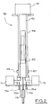
- Figure 1 shows an apparatus 10 including a chamber 20, a piston 30, a base 40, and a piston drive means 50.
- the chamber 20 is a glass cylinder made from hardened, scratch resistant glass. Located near the base of the chamber 20, is a colorimeter 21 including a LED (also reference numeral 21) and a photoelectric sensor 22 on the opposite side of the chamber to the LED 21.
- a colorimeter 21 including a LED (also reference numeral 21) and a photoelectric sensor 22 on the opposite side of the chamber to the LED 21.
- the piston 30 includes a piston head 31, having a main body 32 in turn having an annular flange or lip 33 either end of the head 32.
- the annular lips made of Teflon, clean the chamber's internal glass surface, thereby providing an automatic cleaning mechanism for the internal surface of the chamber.
- the piston 30 includes a piston shaft 34, comprising a pair of elongate arms 35 extending between the piston head 32 and a bar 36 having a central threaded aperture 37.
- a worm drive 51 cooperates with the threaded aperture 37 whereby the rotation of the worm drive 51 by a stepper motor 52 moves the piston 30 up or down the chamber 20.
- the base 40 is provided with a plurality of conduits including a first sample or reagent inlet port 41, selectively in communication with the internal space of the chamber 30 by the operation of a solenoid valve 42.
- the base further includes a second sample or reagent inlet port 43, selectively controlled by a second solenoid valve 44 to control the communication of the second inlet port to the chamber 20.
- the base 40 also includes an outlet 45 including a small recess 46 in which a spring biased ball valve 47 is located. The ball valve 47 is biased to a closed position and is opened by the application by positive pressure by the downward movement of the piston 30.
- the apparatus 10 may be used in a number of ways.
- the apparatus 10 may be used to draw a water sample in through inlet port 41 into the chamber up to a predetermined volume.
- the apparatus 10 controlled by a microprocessor (not shown), may then draw a reagent in through the second inlet port 43.
- the volume of the reagent may be predetermined whereby, after a predetermined amount of time, the colorimeter 21 performs a reading and generates a result based on the specific volume of reagent drawn up by the piston 30.
- the apparatus 10 may perform a titration whereby the piston constantly, gradually draws more reagent through the second inlet port 43 until the colorimeter 21 detects the end point.
- the results may be processed by the microprocessor to provide treatment recommendations.
- the stepper motor 52 is activated to rotate the worm drive 51 to cause downward movement of the piston 30 until all of the sample is ejected through the outlet 45 to waste.
- the chamber may be rinsed several times by drawing either water from the water body or cleansing fluid through the first or second inlet port 41, 43 to flush out contaminants.
- the apparatus 20 may then be used to draw in a treatment solution in an amount determined by the results of the colorimetric analysis through either the first or second inlet port 41, 43 and the treatment solution expelled into the water recirculation system via the outlet 45.
- the apparatus may be used to mix reactants in a closed system and to deliver the resultant composition to the water recirculation system via the outlet 45 without exposing the reactants or the resultant composition to the atmosphere and, critically, to a user.
- chlorine dioxide may be produced and delivered to a body of water using the apparatus 20 by drawing in a precise amount of sodium chloride into the chamber 20 via inlet port 41, drawing a second reactant in the form of an acid in liquid form through inlet port 43 into the chamber 20 in a stoichiometrically predetermined ratio volume.
- the movement of the piston 30 through the first position to the second position provides sufficient turbulence to mix the component reactants together and to produce a resultant chlorine dioxide solution.
- the downward travel of the piston 30 then forces the resultant chlorine dioxide solution through the outlet 45 and into the water recirculation system. This whole operation may be controlled by the microprocessor whereby minimal human intervention is required.
- FIG. 2 there is shown an auto sampling colorimeter 60 according to a second embodiment.
- the colorimeter 60 includes a DC step motor 61 adapted to drive a worm drive 62 which controls the reciprocal movement of a piston 63 and piston head 65 in a reaction chamber 64.
- the colorimetric measurements of the contents of the chamber 64 are carried out by the combined operation of a light emitting diode 66 on one side of the chamber and a diode or sensor 67 on the opposite side, both the LED 66 and sensor 67 being external to the glass or otherwise transparent wall of the chamber 64.
- the colorimeter 60 includes four inlet ports 70 a-d for introducing samples or reagents into the chamber 64.
- valves controlling the communication of the inlet ports 60 a-d with the internal space of the chamber 64 are controlled by solenoids 71, 72, selectively operable according to inputs and programming of a central processor (not shown). Egress of the contents of the chamber is effected through a waste exit valve and port 73 at the base of the colorimeter 60.
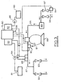
- FIG 3 shows how an auto sampling colorimeter such as apparatus 10 or colorimeter 60 may be used in the maintenance of a body of water such as a pool or spa.
- a waste outlet 98 and a pair of pumps Associated and adjacent the apparatus 10, 60 is a waste outlet 98 and a pair of pumps, a chlorine pump 80 for drawing chlorine from a chlorine drum 81 and an acid pump 82 for drawing acid from an acid drum 83.
- Check valves 84, 85 regulate flow from the respective drums 81, 83. Delivery to the water body is effected via an injection manifold 86 which delivers chlorine and acid solutions into the inlet stream corresponding to pipe 87.
- Pipe 87 transfers water from a filter 88 (having a pump 89 to convey water through the pipe 87).
- In-line in the pipe 87 is a main flow switch 90 and water sample feed line 91 which transfers water samples ex-filter 88 to the colorimeter 10, 60.
- Control valves 92, 93 control the delivery of treated water from the pipe 87 to the pool or spa.
- a spa flow switch 94 is determinative in cooperation with a central processor in indicating to the colorimeter 10, 60 when to switch over to a spa test sequence as opposed to a pool test sequence and whether a filter inlet pipe 95 takes water from the spa or the pool by the selective operation of control valves 96, 97.
Landscapes
- Chemical & Material Sciences (AREA)
- Chemical Kinetics & Catalysis (AREA)
- Physics & Mathematics (AREA)
- Health & Medical Sciences (AREA)
- Life Sciences & Earth Sciences (AREA)
- General Physics & Mathematics (AREA)
- Pathology (AREA)
- Analytical Chemistry (AREA)
- Biochemistry (AREA)
- General Health & Medical Sciences (AREA)
- Immunology (AREA)
- Organic Chemistry (AREA)
- Molecular Biology (AREA)
- Engineering & Computer Science (AREA)
- Plasma & Fusion (AREA)
- Fluid Mechanics (AREA)
- Investigating Or Analyzing Non-Biological Materials By The Use Of Chemical Means (AREA)
- Investigating Or Analysing Materials By The Use Of Chemical Reactions (AREA)
- Transition And Organic Metals Composition Catalysts For Addition Polymerization (AREA)
- Feeding, Discharge, Calcimining, Fusing, And Gas-Generation Devices (AREA)
Claims (20)
- Vorrichtung (10) zum Messen, Mischen und/oder Analysieren eines Bereichs von kleinen Volumina von Fluiden mit einem hohen Präzisionsgrad, wobei die Vorrichtung (10) folgendes enthält:a) eine einzelne Reaktionskammer (20) und eine Basis (40);b) einen sich hin- und herbewegbaren Kolben (30) in der Kammer (20);c) einen ersten Einlaß (41) zu der Kammer (20) in Kommunikation mit einer oder mehreren Fluidquellen, von denen ein Teil eines ersten Fluids des einen oder der mehreren Fluide dafür ausgelegt ist, in die Kammer (20) gesaugt zu werden;d) mindestens einen weiteren Einlaß (43) mit einem zweiten Einlaß zu der Kammer (20) in Kommunikation mit einer oder mehreren Fluidquellen, von denen ein Teil eines zweiten Fluids des einen oder der mehreren Fluide dafür ausgelegt ist, in die Kammer (20) gesaugt zu werden; unde) einen abdichtbaren Auslaß (45), wobeif) der Kolben (30) innerhalb der Kammer (20) betätigt werden kann, um das Innenvolumen der Kammer (20) selektiv und präzise zu variieren;g) wobei der erste Einlaß (41) ein erstes Ventil (42) aufweist, das selektiv betätigt werden kann, um den Fluß des ersten Teils in die Kammer (20) durch die Bewegung des Kolbens (30) innerhalb der Kammer (20) von der Basis (40) weg zu gestatten, bis ein vorbestimmtes Volumen des ersten Fluids in die Kammer (20) gesaugt ist;h) wobei der zweite Einlaß (43) ein zweites Ventil (44) aufweist, das selektiv betätigt werden kann, um den Fluß des zweiten Teils in die Kammer (20) durch die Bewegung des Kolbens (30) innerhalb der Kammer (20) zu gestatten, um das zweite Fluid progressiv in die Kammer (20) zu saugen, bis eine vorbestimmte Bedingung erfüllt ist, einschließlich dem präzisen Dosieren eines Volumens des zweiten Fluids oder der Beendigung einer Reaktion mit dem ersten und zweiten Teil in der Kammer (20);i) wobei der Kolben (30) dafür ausgelegt ist, in seine Ausgangsposition zurückzukehren, um den Inhalt der Kammer (20) durch den Auslaß (45) zu entleeren, bis die ganze Probe durch den Auslaß (45) ausgeworfen worden ist,wobei der Auslaß (45) durch ein Ausgangsventil (47) abgedichtet ist,
dadurch gekennzeichnet, daß
sich das Auslaßventil (47) in der Basis (40) bei der inneren Oberfläche der Kammer (20) befindet. - Vorrichtung nach Anspruch 1, dadurch gekennzeichnet, daß sich der erste (41) und zweite (43) Einlaß und der Auslaß (45) in der Basis (40) befinden.
- Vorrichtung nach Anspruch 1, dadurch gekennzeichnet, daß sich das erste (42) und zweite (44) Ventil in der Basis (40) befinden.
- Vorrichtung nach Anspruch 1, dadurch gekennzeichnet, daß der Kolben (30) ein Paar beabstandeter Ringlippen (33) enthält, die dahingehend arbeiten, die innere Oberfläche der Kammer (20) zu reinigen.
- Vorrichtung nach Anspruch 1, dadurch gekennzeichnet, daß die Vorrichtung (10) einen dritten Einlaß zu der Kammer (20) in Kommunikation mit einer dritten Fluidquelle enthält, wovon ein Teil des dritten Fluids dafür ausgelegt ist, durch die Betätigung des Kolbens (30) in die Kammer (20) gesaugt zu werden, wodurch die erste Fluidquelle eine Quelle eines ersten Reagens ist, die zweite Fluidquelle eine Quelle eines zweiten Reagens ist und die dritte Fluidquelle ein Wasserkörper einschließlich eines Beckens, einer Heilquelle, eines Kühlwassertanks oder -turms oder einer Trinkwasserquelle ist.
- Vorrichtung nach Anspruch 1, dadurch gekennzeichnet, daß die Vorrichtung (10) weiterhin einen Analysator für einen optischen Wert zum Analysieren des Inhalts der Kammer (20) enthält.
- Vorrichtung nach Anspruch 6, dadurch gekennzeichnet, daß der Analysator für einen optischen Wert anzeigt, wann die vorbestimmte Bedingung erfüllt ist.
- Vorrichtung nach Anspruch 6, dadurch gekennzeichnet, daß die Vorrichtung (10) einen Computerprozessor zum Steuern des Kolbens (30), des ersten Ventils (42) und des mindestens einen weiteren Ventils einschließlich des zweiten Ventils (44) und des Auslasses (45) enthält und der Analysator für einen optischen Wert dem Computerprozessor anzeigt, wann die vorbestimmte Bedingung erfüllt ist.
- Vorrichtung nach Anspruch 1 oder 5, dadurch gekennzeichnet, daß die erste Fluidquelle ein erstes Reagens enthält und die zweite Fluidquelle ein zweites Reagens enthält, wodurch die Vorrichtung (10) dafür ausgelegt ist, das erste und zweite Reagens in präzisen stöchiometrischen Verhältnissen zu mischen und miteinander umzusetzen, um eine aktive Zusammensetzung zu erhalten.
- Vorrichtung nach Anspruch 9, dadurch gekennzeichnet, daß das erste Reagens Natriumchlorit ist, das zweite Reagens eine Säure in flüssiger Form ist, wobei die aktive Zusammensetzung Chlordioxid enthält und die Vorrichtung (10) ein geschlossenes System zum Mischen der Reaktanten ohne Gefährden eines Benutzers bereitstellt.
- Vorrichtung nach Anspruch 9, wenn von Anspruch 5 abhängig, dadurch gekennzeichnet, daß der Auslaß (45) optional in Kommunikation mit einer Abfallentsorgung zu dem einen Zeitpunkt oder dem Wasserkörper zu einem anderen Zeitpunkt über Schaltmittel steht und die Vorrichtung (10) dafür ausgelegt ist, die aktive Zusammensetzung durch den Auslaß (45) über das Auslaßventil (47) zu dem Wasserkörper auszutreiben.
- Vorrichtung nach Anspruch 8, dadurch gekennzeichnet, daß die erste Fluidquelle in Form eines Benutzerprobenempfangsmittels vorliegt, das dafür ausgelegt ist, das erste Fluid in Kommunikation mit der Kammer (20) zu plazieren; und die Vorrichtung weiterhin Zahlungsempfangsmittel enthält, die dafür ausgelegt sind, den Computerprozessor bei Empfang einer vorbestimmten Zahlung von dem Nutzer betätigbar zu machen.
- Vorrichtung nach Anspruch 12, dadurch gekennzeichnet, daß das Probenempfangsmittel die Probe in einem Probengefäß empfängt, das auf dem Empfangsmittel oder in eine Vertiefung plaziert ist, in die die Probe wie etwa durch Gießen hineingegeben werden kann.
- Vorrichtung nach Anspruch 12, dadurch gekennzeichnet, daß die Vorrichtung (10) weiterhin ein Informationsdisplay und Eingabemittel enthält.
- Vorrichtung nach Anspruch 14, dadurch gekennzeichnet, daß das Display dafür ausgelegt ist, vom Benutzer Informationen hinsichtlich einer Reihe vorbestimmter Werte anzufordern, einschließlich Volumen der dritten Fluidquelle, dem Material der inneren Oberfläche des Gefäßes, das die dritte Fluidquelle enthält, existierende Behandlungsregimeart und zum Bereitstellen von Rückkopplung einschließlich Rückkopplung, wenn von dem Benutzer unsinnige Werte eingegeben werden.
- Verfahren zum Testen eines kleinen Volumens einer Fluidzusammensetzung, wobei das Verfahren die folgenden Schritte beinhaltet:a) Öffnen eines ersten Einlasses (41) in Kommunikation mit einer Kammer (20), wodurch die Kammer (20) in Kommunikation mit einer Quelle eines ersten Fluids plaziert wird;b) Betätigen eines Kolbens (30) in der Kammer (20), um den Kolben (30) von einer Basis (40) der Kammer (20) zu einer ersten Position wegzubewegen, um ein vorbestimmtes und präzises Volumen einer Menge der ersten Flüssigkeit von der ersten Fluidquelle durch den ersten Einlaß (41) in die Kammer (20) zu saugen;c) Schließen des ersten Einlasses (41);d) Öffnen eines zweiten Einlasses (43) in Kommunikation mit der Kammer (20), wodurch die Kammer (20) in Kommunikation mit einer Quelle eines zweiten Fluids plaziert wird;e) Betätigen des Kolbens (30), um den Kolben (30) aus der ersten Position zu einer zweiten Position zu bewegen, um ein zweites Fluid von der zweiten Fluidquelle durch den zweiten Einlaß (43) in die Kammer (20) zu saugen, bis eine vorbestimmte Bedingung erfüllt worden ist, wobei sich das erste und zweite Fluid mischen, um eine Zusammensetzung zu bilden;f) Schließen des zweiten Einlasses (43);g) Zurückführen des Kolbens (30) in seine Ausgangsposition, um dadurch die Zusammensetzung durch einen selektiv betätigbaren Auslaß (45) über ein Auslaßventil (47) auszutreiben, bis die ganze Probe ausgeworfen ist,dadurch gekennzeichnet, daß
sich das Auslaßventil (47) in der Basis (40) und bei der inneren Oberfläche der Kammer (20) befindet. - Verfahren nach Anspruch 16, dadurch gekennzeichnet, daß sich das erste und zweite Fluid in einem geschlossenen System befinden und Liefern der resultierenden aktiven Zusammensetzung an ein Wasserumlaufsystem.
- Verfahren nach Anspruch 16, dadurch gekennzeichnet, daß das erste und zweite Fluid das erste beziehungsweise zweite Reagens sind, wodurch sich bei Mischen und Umsetzen im Schritt g) das erste und zweite Reagens vereinigen, um eine aktive Zusammensetzung einschließlich Chlordioxid auszubilden.
- Verfahren nach Anspruch 16, dadurch gekennzeichnet, daß die vorbestimmte Bedingung erfüllt ist, wenn ein Analysator für einen optischen Wert, der dafür ausgelegt ist, ein Signal durch die Kammer (20) zu übertragen und das modifizierte Signal, das durch die Kammer (20) übertragen worden ist, zu empfangen, einen bestimmten optischen Wert detektiert.
- Verfahren nach Anspruch 19, dadurch gekennzeichnet, daß der Analysator für einen optischen Wert ein Kolorimeter ist (21).
Applications Claiming Priority (3)
| Application Number | Priority Date | Filing Date | Title |
|---|---|---|---|
| AUPS2298A AUPS229802A0 (en) | 2002-05-07 | 2002-05-07 | Apparatus for mixing and/or testing small volumes of fluids |
| AUPS229802 | 2002-05-07 | ||
| PCT/AU2003/000539 WO2003095952A1 (en) | 2002-05-07 | 2003-05-07 | Apparatus for mixing and/or testing small volumes of fluids |
Publications (3)
| Publication Number | Publication Date |
|---|---|
| EP1511976A1 EP1511976A1 (de) | 2005-03-09 |
| EP1511976A4 EP1511976A4 (de) | 2006-09-06 |
| EP1511976B1 true EP1511976B1 (de) | 2009-07-29 |
Family
ID=3835868
Family Applications (1)
| Application Number | Title | Priority Date | Filing Date |
|---|---|---|---|
| EP03729698A Expired - Lifetime EP1511976B1 (de) | 2002-05-07 | 2003-05-07 | Vorrichtung zum mischen und/ oder testen kleiner fluidvolumen |
Country Status (9)
| Country | Link |
|---|---|
| US (1) | US7988916B2 (de) |
| EP (1) | EP1511976B1 (de) |
| AT (1) | ATE438087T1 (de) |
| AU (1) | AUPS229802A0 (de) |
| CA (1) | CA2483477C (de) |
| DE (1) | DE60328601D1 (de) |
| ES (1) | ES2331471T3 (de) |
| NZ (1) | NZ537012A (de) |
| WO (1) | WO2003095952A1 (de) |
Families Citing this family (36)
| Publication number | Priority date | Publication date | Assignee | Title |
|---|---|---|---|---|
| US7617953B2 (en) * | 2005-09-29 | 2009-11-17 | Nordson Corporation | Pneumatic dispensing system with linear actuation and method |
| EP1955061A1 (de) * | 2005-11-28 | 2008-08-13 | BTG Instruments GmbH | Vorrichtung zur analyse einer probeflüssigkeit |
| WO2007070035A1 (en) * | 2005-12-12 | 2007-06-21 | Carrier Commerical Refrigeration, Inc. | Adapter plate in a pump of a beverage system |
| EP1859873A1 (de) * | 2006-05-22 | 2007-11-28 | JohnsonDiversey, Inc. | Verfahren und Vorrichtung zum Waschen eines Glasbehälters |
| WO2008061315A1 (en) * | 2006-11-24 | 2008-05-29 | Aqualysis Pty Ltd | Chemical analyser |
| US7671994B2 (en) * | 2007-05-14 | 2010-03-02 | Watkins Manufacturing Corporation | Method for measuring chemical levels using pH shift |
| US7639361B2 (en) * | 2007-05-14 | 2009-12-29 | Watkins Manufacturing Corporation | Apparatus for measuring chemical levels using pH shift |
| CN201404734Y (zh) * | 2009-04-28 | 2010-02-17 | 厦门市毕恩生物技术有限公司 | 底部控制式标本过滤容器 |
| US9618438B2 (en) * | 2009-09-09 | 2017-04-11 | ClearCorp | System and method for analyzing water samples in a water processing facility |
| US8319176B2 (en) | 2010-04-01 | 2012-11-27 | Electro Scientific Industries, Inc. | Sample chamber for laser ablation inductively coupled plasma mass spectroscopy |
| US9016110B2 (en) * | 2010-11-22 | 2015-04-28 | Nalco Company | Apparatus for on-line continuous chlorine analysis in turbid water and process streams |
| US9134289B2 (en) * | 2010-11-22 | 2015-09-15 | Nalco Company | Apparatus for on-line continuous chlorine analysis in turbid water and process streams |
| WO2015077863A1 (en) * | 2013-11-29 | 2015-06-04 | Sanecotec Ltd. | Water integrity and apparatus for measuring hydrogen peroxide in water treatment and distribution systems |
| DE102014006317B3 (de) * | 2014-04-30 | 2015-05-07 | Gebrüder Heyl Analysentechnik GmbH & Co KG | Verfahren zur Erweiterung des Messbereiches von fotometrischen Systemen |
| CN104147952B (zh) * | 2014-08-21 | 2016-08-24 | 中蓝晨光化工研究设计院有限公司 | 一种用于芳纶ⅱ预聚合的物料静态混合器 |
| US9776888B1 (en) * | 2015-01-05 | 2017-10-03 | Data20 | Water monitoring device and method |
| US10287180B1 (en) * | 2015-01-05 | 2019-05-14 | Sutro Connect Inc. | Water monitoring device with replaceable reagent cartridge |
| JP6609985B2 (ja) * | 2015-05-13 | 2019-11-27 | 三菱マテリアル株式会社 | 濃度測定装置、濃度測定方法、制御プログラム |
| US10479698B2 (en) * | 2016-10-31 | 2019-11-19 | Mohamad Tarek Dajani | System and method for an automated water testing device |
| CN106706536B (zh) * | 2017-02-09 | 2023-06-23 | 天健创新(北京)监测仪表股份有限公司 | 一种管网末梢的浊度检测装置 |
| DE102017211311A1 (de) * | 2017-07-04 | 2019-01-10 | Heraeus Deutschland GmbH & Co. KG | Prozesssteuerung mit Farbsensor |
| GB2565061B (en) * | 2017-07-28 | 2020-09-02 | Adey Holdings 2008 Ltd | Optical testing of central heating system water |
| EP3700665A2 (de) * | 2017-10-24 | 2020-09-02 | Dow Global Technologies LLC | Pulskompressionsreaktoren und verfahren zu deren betrieb |
| CN107913657A (zh) * | 2017-11-27 | 2018-04-17 | 朱新福 | 往复式搅拌器和使用该搅拌器的反应釜 |
| CN107843705B (zh) * | 2017-12-21 | 2024-07-26 | 重庆多邦科技股份有限公司 | 一种用于分析地下水的水质分析仪 |
| CN109100466B (zh) * | 2018-09-17 | 2020-10-27 | 山东工业职业学院 | 一种高精度调控滴定装置 |
| US10989630B2 (en) * | 2018-10-03 | 2021-04-27 | Advanced Sampling Process Instruments Ltd. | Sampling apparatus |
| US11327066B2 (en) * | 2019-01-10 | 2022-05-10 | Haier Us Appliance Solutions, Inc. | Water contaminant measurement system and methods for measuring concentration levels of contaminants in water |
| US11754545B2 (en) * | 2019-02-26 | 2023-09-12 | Pentair Water Pool & Spa, Inc. | Water quality monitor system and method |
| GB2597080B (en) * | 2020-07-14 | 2022-11-23 | Adey Holdings 2008 Ltd | Automatic testing and dosing of central heating and/or cooling systems |
| US12123803B2 (en) * | 2020-08-27 | 2024-10-22 | University Of Idaho | Rapid compression machine with electrical drive and methods for use thereof |
| EP4256306B1 (de) | 2020-12-04 | 2025-02-26 | Kofler GmbH | Pipettierroboter zur bestimmung zumindest einer wassereigenschaft |
| CN114653299B (zh) * | 2022-04-02 | 2023-03-14 | 郑州三华科技实业有限公司 | 液体注出方法和液体注出装置 |
| WO2025245157A1 (en) | 2024-05-24 | 2025-11-27 | Zodiac Pool Systems Llc | Inline water monitoring system |
| US20260061424A1 (en) | 2024-08-29 | 2026-03-05 | Zodiac Pool Systems Llc | Cartridge with liquid reagents for automatic chemistry analysis of recreational water including pools and spas |
| CN120838548B (zh) * | 2025-09-23 | 2025-12-12 | 河南润源环保材料有限公司 | 一种颚破研磨一体机 |
Citations (1)
| Publication number | Priority date | Publication date | Assignee | Title |
|---|---|---|---|---|
| US3063813A (en) * | 1957-09-10 | 1962-11-13 | Bayer Ag | Apparatus for producing fluid mixtures |
Family Cites Families (19)
| Publication number | Priority date | Publication date | Assignee | Title |
|---|---|---|---|---|
| US3953136A (en) * | 1974-03-15 | 1976-04-27 | Hach Chemical Company | Method and apparatus for automatically analyzing fluids |
| FR2351402A1 (fr) * | 1976-05-10 | 1977-12-09 | Marteau Dautry Eric | Diluteur reglable |
| US4205953A (en) * | 1977-12-22 | 1980-06-03 | Olin Corporation | Calcium magnesium analyzer |
| DE3446756C1 (de) | 1984-12-21 | 1985-10-31 | Betz, Michael, Dr., 2300 Molfsee | Photometer zum Analysieren fluessiger Medien |
| US4663126A (en) * | 1985-03-26 | 1987-05-05 | Gould Corby J | Pool water test instrument |
| US4715710A (en) * | 1986-02-19 | 1987-12-29 | Hach Company | Pump colorimetric analyzer |
| US4861451A (en) * | 1987-11-23 | 1989-08-29 | Hammond Royce Corporation Pty. Limited | Chlorinator cell |
| EP0470070B1 (de) | 1989-03-06 | 1994-12-07 | SILVERI, Michael A | Unterwasserschwimmbadreiniger mit elektronischer zelle |
| DE3934024A1 (de) * | 1989-10-12 | 1991-04-18 | Wildanger Hans Joerg | Vorrichtung zur reproduzierbaren zumischung von fluessigkeiten zu fluessigen proben in automatischen analysesystemen |
| US5635070A (en) * | 1990-07-13 | 1997-06-03 | Isco, Inc. | Apparatus and method for supercritical fluid extraction |
| US5221444A (en) * | 1991-11-15 | 1993-06-22 | Silveri Michael A | Electrolytic pool purifier system |
| AU682055B2 (en) | 1993-10-27 | 1997-09-18 | Alcides dos Santos Lisboa | Electrolytic cell for the generation of hypo halogenites for water treatment |
| AUPM864494A0 (en) | 1994-10-07 | 1994-11-03 | Clearwater Australia Pty Limited | Electrolytic chlorination |
| AU6904496A (en) * | 1995-08-22 | 1997-03-19 | Andcare, Inc. | Handheld electromonitor device |
| AU7340596A (en) * | 1995-10-09 | 1997-04-30 | Korea Ocean Research & Development Institute | An automated analyzing apparatus for measuring water quality with a cylinder-shaped syringe unit |
| EP0787535B1 (de) * | 1996-01-31 | 2002-05-02 | Wilhelm A. Keller | Vorrichtung zur Abgabe von wenigstens zwei Komponenten |
| US6082204A (en) * | 1998-12-18 | 2000-07-04 | Munderloh; Neil | Titration method using a syringe |
| AU2003902831A0 (en) | 2003-06-06 | 2003-06-26 | Ben Bremauer | Electrolytic sanitiser generator |
| GB2408401B (en) * | 2003-11-24 | 2006-05-03 | Zarlink Semiconductor Ltd | A network |
-
2002
- 2002-05-07 AU AUPS2298A patent/AUPS229802A0/en not_active Abandoned
-
2003
- 2003-05-07 ES ES03729698T patent/ES2331471T3/es not_active Expired - Lifetime
- 2003-05-07 AT AT03729698T patent/ATE438087T1/de not_active IP Right Cessation
- 2003-05-07 WO PCT/AU2003/000539 patent/WO2003095952A1/en not_active Ceased
- 2003-05-07 US US10/513,918 patent/US7988916B2/en active Active
- 2003-05-07 DE DE60328601T patent/DE60328601D1/de not_active Expired - Lifetime
- 2003-05-07 NZ NZ537012A patent/NZ537012A/en not_active IP Right Cessation
- 2003-05-07 CA CA2483477A patent/CA2483477C/en not_active Expired - Lifetime
- 2003-05-07 EP EP03729698A patent/EP1511976B1/de not_active Expired - Lifetime
Patent Citations (1)
| Publication number | Priority date | Publication date | Assignee | Title |
|---|---|---|---|---|
| US3063813A (en) * | 1957-09-10 | 1962-11-13 | Bayer Ag | Apparatus for producing fluid mixtures |
Also Published As
| Publication number | Publication date |
|---|---|
| WO2003095952A1 (en) | 2003-11-20 |
| CA2483477A1 (en) | 2003-11-20 |
| ES2331471T3 (es) | 2010-01-05 |
| AUPS229802A0 (en) | 2002-06-13 |
| NZ537012A (en) | 2006-05-26 |
| ATE438087T1 (de) | 2009-08-15 |
| EP1511976A1 (de) | 2005-03-09 |
| EP1511976A4 (de) | 2006-09-06 |
| DE60328601D1 (de) | 2009-09-10 |
| CA2483477C (en) | 2012-12-04 |
| US7988916B2 (en) | 2011-08-02 |
| US20050276724A1 (en) | 2005-12-15 |
Similar Documents
| Publication | Publication Date | Title |
|---|---|---|
| US7988916B2 (en) | Apparatus for mixing and/or testing small volumes of fluids | |
| AU2020239698C1 (en) | Multi parameter swimming pool fluid analysis and regulating method and device | |
| US5817954A (en) | Automated analyzing apparatus for measuring water quality with a cylinder-shaped syringe unit | |
| EP2596347B1 (de) | Alkalinitätsanalyse mittels lab-on-chip | |
| US20130149790A1 (en) | Sample preparation system for an analytical system for determining a measured variable of a liquid sample | |
| AU2019433191B2 (en) | Water monitoring device with replaceable reagent cartridge | |
| US10577256B1 (en) | Water monitoring device with replaceable reagent cartridge | |
| US20250003885A1 (en) | Water monitoring device with replaceable reagent cartridge | |
| CN107966406A (zh) | 一种水质自动检测设备 | |
| US20140087476A1 (en) | Optical sensor for bromide ion | |
| KR102571713B1 (ko) | 통합 생태독성감시 장치 | |
| AU2003240282B8 (en) | Apparatus for mixing and/or testing small volumes of fluids | |
| EP3924724A1 (de) | Kolorimetrischer nachweis von aluminium in einer wässrigen probe | |
| JP2001318057A (ja) | 残留塩素測定方法及びその装置 | |
| US12487222B2 (en) | Method for determining a chemical intake capacity of a process medium in a measuring point and measuring point for determining a chemical intake capacity of a process medium | |
| EP1697723A1 (de) | Messzelle | |
| CN208537538U (zh) | 一种微流控芯片 | |
| Kim | Development and application of integrated ozone contactor design and optimization tools | |
| CN222482185U (zh) | 一种水质在线滴定分析仪 | |
| US20170370892A1 (en) | System for determining chlorine demand in water | |
| WO2026030569A1 (en) | Electro-mechanical analytical chemistry system and method | |
| Demko et al. | Analyzing Analyzers: An Evaluation Of On-Line Nutrient Analyzers At The City of Plant City Water Reclamation Facility |
Legal Events
| Date | Code | Title | Description |
|---|---|---|---|
| PUAI | Public reference made under article 153(3) epc to a published international application that has entered the european phase |
Free format text: ORIGINAL CODE: 0009012 |
|
| 17P | Request for examination filed |
Effective date: 20041203 |
|
| AK | Designated contracting states |
Kind code of ref document: A1 Designated state(s): AT BE BG CH CY CZ DE DK EE ES FI FR GB GR HU IE IT LI LU MC NL PT RO SE SI SK TR |
|
| AX | Request for extension of the european patent |
Extension state: AL LT LV MK |
|
| DAX | Request for extension of the european patent (deleted) | ||
| A4 | Supplementary search report drawn up and despatched |
Effective date: 20060803 |
|
| 17Q | First examination report despatched |
Effective date: 20071031 |
|
| GRAP | Despatch of communication of intention to grant a patent |
Free format text: ORIGINAL CODE: EPIDOSNIGR1 |
|
| GRAS | Grant fee paid |
Free format text: ORIGINAL CODE: EPIDOSNIGR3 |
|
| GRAA | (expected) grant |
Free format text: ORIGINAL CODE: 0009210 |
|
| AK | Designated contracting states |
Kind code of ref document: B1 Designated state(s): AT BE BG CH CY CZ DE DK EE ES FI FR GB GR HU IE IT LI LU MC NL PT RO SE SI SK TR |
|
| REG | Reference to a national code |
Ref country code: GB Ref legal event code: FG4D |
|
| REG | Reference to a national code |
Ref country code: CH Ref legal event code: EP |
|
| REG | Reference to a national code |
Ref country code: IE Ref legal event code: FG4D |
|
| REF | Corresponds to: |
Ref document number: 60328601 Country of ref document: DE Date of ref document: 20090910 Kind code of ref document: P |
|
| NLV1 | Nl: lapsed or annulled due to failure to fulfill the requirements of art. 29p and 29m of the patents act | ||
| REG | Reference to a national code |
Ref country code: ES Ref legal event code: FG2A Ref document number: 2331471 Country of ref document: ES Kind code of ref document: T3 |
|
| PG25 | Lapsed in a contracting state [announced via postgrant information from national office to epo] |
Ref country code: SE Free format text: LAPSE BECAUSE OF FAILURE TO SUBMIT A TRANSLATION OF THE DESCRIPTION OR TO PAY THE FEE WITHIN THE PRESCRIBED TIME-LIMIT Effective date: 20090729 Ref country code: FI Free format text: LAPSE BECAUSE OF FAILURE TO SUBMIT A TRANSLATION OF THE DESCRIPTION OR TO PAY THE FEE WITHIN THE PRESCRIBED TIME-LIMIT Effective date: 20090729 Ref country code: AT Free format text: LAPSE BECAUSE OF FAILURE TO SUBMIT A TRANSLATION OF THE DESCRIPTION OR TO PAY THE FEE WITHIN THE PRESCRIBED TIME-LIMIT Effective date: 20090729 |
|
| PG25 | Lapsed in a contracting state [announced via postgrant information from national office to epo] |
Ref country code: NL Free format text: LAPSE BECAUSE OF FAILURE TO SUBMIT A TRANSLATION OF THE DESCRIPTION OR TO PAY THE FEE WITHIN THE PRESCRIBED TIME-LIMIT Effective date: 20090729 Ref country code: SI Free format text: LAPSE BECAUSE OF FAILURE TO SUBMIT A TRANSLATION OF THE DESCRIPTION OR TO PAY THE FEE WITHIN THE PRESCRIBED TIME-LIMIT Effective date: 20090729 |
|
| PG25 | Lapsed in a contracting state [announced via postgrant information from national office to epo] |
Ref country code: BG Free format text: LAPSE BECAUSE OF FAILURE TO SUBMIT A TRANSLATION OF THE DESCRIPTION OR TO PAY THE FEE WITHIN THE PRESCRIBED TIME-LIMIT Effective date: 20091029 Ref country code: PT Free format text: LAPSE BECAUSE OF FAILURE TO SUBMIT A TRANSLATION OF THE DESCRIPTION OR TO PAY THE FEE WITHIN THE PRESCRIBED TIME-LIMIT Effective date: 20091129 |
|
| PG25 | Lapsed in a contracting state [announced via postgrant information from national office to epo] |
Ref country code: RO Free format text: LAPSE BECAUSE OF FAILURE TO SUBMIT A TRANSLATION OF THE DESCRIPTION OR TO PAY THE FEE WITHIN THE PRESCRIBED TIME-LIMIT Effective date: 20090729 Ref country code: EE Free format text: LAPSE BECAUSE OF FAILURE TO SUBMIT A TRANSLATION OF THE DESCRIPTION OR TO PAY THE FEE WITHIN THE PRESCRIBED TIME-LIMIT Effective date: 20090729 Ref country code: CZ Free format text: LAPSE BECAUSE OF FAILURE TO SUBMIT A TRANSLATION OF THE DESCRIPTION OR TO PAY THE FEE WITHIN THE PRESCRIBED TIME-LIMIT Effective date: 20090729 Ref country code: DK Free format text: LAPSE BECAUSE OF FAILURE TO SUBMIT A TRANSLATION OF THE DESCRIPTION OR TO PAY THE FEE WITHIN THE PRESCRIBED TIME-LIMIT Effective date: 20090729 |
|
| PG25 | Lapsed in a contracting state [announced via postgrant information from national office to epo] |
Ref country code: SK Free format text: LAPSE BECAUSE OF FAILURE TO SUBMIT A TRANSLATION OF THE DESCRIPTION OR TO PAY THE FEE WITHIN THE PRESCRIBED TIME-LIMIT Effective date: 20090729 Ref country code: BE Free format text: LAPSE BECAUSE OF FAILURE TO SUBMIT A TRANSLATION OF THE DESCRIPTION OR TO PAY THE FEE WITHIN THE PRESCRIBED TIME-LIMIT Effective date: 20090729 |
|
| PLBE | No opposition filed within time limit |
Free format text: ORIGINAL CODE: 0009261 |
|
| STAA | Information on the status of an ep patent application or granted ep patent |
Free format text: STATUS: NO OPPOSITION FILED WITHIN TIME LIMIT |
|
| 26N | No opposition filed |
Effective date: 20100503 |
|
| PG25 | Lapsed in a contracting state [announced via postgrant information from national office to epo] |
Ref country code: GR Free format text: LAPSE BECAUSE OF FAILURE TO SUBMIT A TRANSLATION OF THE DESCRIPTION OR TO PAY THE FEE WITHIN THE PRESCRIBED TIME-LIMIT Effective date: 20091030 |
|
| PG25 | Lapsed in a contracting state [announced via postgrant information from national office to epo] |
Ref country code: MC Free format text: LAPSE BECAUSE OF NON-PAYMENT OF DUE FEES Effective date: 20100531 |
|
| PG25 | Lapsed in a contracting state [announced via postgrant information from national office to epo] |
Ref country code: IT Free format text: LAPSE BECAUSE OF FAILURE TO SUBMIT A TRANSLATION OF THE DESCRIPTION OR TO PAY THE FEE WITHIN THE PRESCRIBED TIME-LIMIT Effective date: 20090729 |
|
| PG25 | Lapsed in a contracting state [announced via postgrant information from national office to epo] |
Ref country code: IE Free format text: LAPSE BECAUSE OF NON-PAYMENT OF DUE FEES Effective date: 20100507 |
|
| PG25 | Lapsed in a contracting state [announced via postgrant information from national office to epo] |
Ref country code: CY Free format text: LAPSE BECAUSE OF FAILURE TO SUBMIT A TRANSLATION OF THE DESCRIPTION OR TO PAY THE FEE WITHIN THE PRESCRIBED TIME-LIMIT Effective date: 20090729 |
|
| PG25 | Lapsed in a contracting state [announced via postgrant information from national office to epo] |
Ref country code: HU Free format text: LAPSE BECAUSE OF FAILURE TO SUBMIT A TRANSLATION OF THE DESCRIPTION OR TO PAY THE FEE WITHIN THE PRESCRIBED TIME-LIMIT Effective date: 20100130 Ref country code: LU Free format text: LAPSE BECAUSE OF NON-PAYMENT OF DUE FEES Effective date: 20100507 |
|
| PG25 | Lapsed in a contracting state [announced via postgrant information from national office to epo] |
Ref country code: TR Free format text: LAPSE BECAUSE OF FAILURE TO SUBMIT A TRANSLATION OF THE DESCRIPTION OR TO PAY THE FEE WITHIN THE PRESCRIBED TIME-LIMIT Effective date: 20090729 |
|
| REG | Reference to a national code |
Ref country code: FR Ref legal event code: PLFP Year of fee payment: 14 |
|
| REG | Reference to a national code |
Ref country code: FR Ref legal event code: PLFP Year of fee payment: 15 |
|
| REG | Reference to a national code |
Ref country code: FR Ref legal event code: PLFP Year of fee payment: 16 |
|
| PGFP | Annual fee paid to national office [announced via postgrant information from national office to epo] |
Ref country code: GB Payment date: 20220524 Year of fee payment: 20 Ref country code: FR Payment date: 20220526 Year of fee payment: 20 Ref country code: ES Payment date: 20220614 Year of fee payment: 20 Ref country code: DE Payment date: 20220527 Year of fee payment: 20 |
|
| PGFP | Annual fee paid to national office [announced via postgrant information from national office to epo] |
Ref country code: CH Payment date: 20220520 Year of fee payment: 20 |
|
| REG | Reference to a national code |
Ref country code: DE Ref legal event code: R071 Ref document number: 60328601 Country of ref document: DE |
|
| REG | Reference to a national code |
Ref country code: CH Ref legal event code: PL |
|
| REG | Reference to a national code |
Ref country code: ES Ref legal event code: FD2A Effective date: 20230526 |
|
| REG | Reference to a national code |
Ref country code: GB Ref legal event code: PE20 Expiry date: 20230506 |
|
| PG25 | Lapsed in a contracting state [announced via postgrant information from national office to epo] |
Ref country code: ES Free format text: LAPSE BECAUSE OF EXPIRATION OF PROTECTION Effective date: 20230508 |
|
| PG25 | Lapsed in a contracting state [announced via postgrant information from national office to epo] |
Ref country code: GB Free format text: LAPSE BECAUSE OF EXPIRATION OF PROTECTION Effective date: 20230506 |