EP1511525B1 - A cartridge for electrohemodialysis - Google Patents
A cartridge for electrohemodialysis Download PDFInfo
- Publication number
- EP1511525B1 EP1511525B1 EP02795474A EP02795474A EP1511525B1 EP 1511525 B1 EP1511525 B1 EP 1511525B1 EP 02795474 A EP02795474 A EP 02795474A EP 02795474 A EP02795474 A EP 02795474A EP 1511525 B1 EP1511525 B1 EP 1511525B1
- Authority
- EP
- European Patent Office
- Prior art keywords
- blood
- cartridge
- hemodialysis
- compartment
- plasma
- Prior art date
- Legal status (The legal status is an assumption and is not a legal conclusion. Google has not performed a legal analysis and makes no representation as to the accuracy of the status listed.)
- Expired - Lifetime
Links
Images

Classifications
-
- A—HUMAN NECESSITIES
- A61—MEDICAL OR VETERINARY SCIENCE; HYGIENE
- A61M—DEVICES FOR INTRODUCING MEDIA INTO, OR ONTO, THE BODY; DEVICES FOR TRANSDUCING BODY MEDIA OR FOR TAKING MEDIA FROM THE BODY; DEVICES FOR PRODUCING OR ENDING SLEEP OR STUPOR
- A61M1/00—Suction or pumping devices for medical purposes; Devices for carrying-off, for treatment of, or for carrying-over, body-liquids; Drainage systems
- A61M1/14—Dialysis systems; Artificial kidneys; Blood oxygenators ; Reciprocating systems for treatment of body fluids, e.g. single needle systems for hemofiltration or pheresis
- A61M1/16—Dialysis systems; Artificial kidneys; Blood oxygenators ; Reciprocating systems for treatment of body fluids, e.g. single needle systems for hemofiltration or pheresis with membranes
-
- A—HUMAN NECESSITIES
- A61—MEDICAL OR VETERINARY SCIENCE; HYGIENE
- A61M—DEVICES FOR INTRODUCING MEDIA INTO, OR ONTO, THE BODY; DEVICES FOR TRANSDUCING BODY MEDIA OR FOR TAKING MEDIA FROM THE BODY; DEVICES FOR PRODUCING OR ENDING SLEEP OR STUPOR
- A61M1/00—Suction or pumping devices for medical purposes; Devices for carrying-off, for treatment of, or for carrying-over, body-liquids; Drainage systems
- A61M1/14—Dialysis systems; Artificial kidneys; Blood oxygenators ; Reciprocating systems for treatment of body fluids, e.g. single needle systems for hemofiltration or pheresis
- A61M1/28—Peritoneal dialysis ; Other peritoneal treatment, e.g. oxygenation
- A61M1/287—Dialysates therefor
-
- B—PERFORMING OPERATIONS; TRANSPORTING
- B01—PHYSICAL OR CHEMICAL PROCESSES OR APPARATUS IN GENERAL
- B01D—SEPARATION
- B01D57/00—Separation, other than separation of solids, not fully covered by a single other group or subclass, e.g. B03C
- B01D57/02—Separation, other than separation of solids, not fully covered by a single other group or subclass, e.g. B03C by electrophoresis
-
- B—PERFORMING OPERATIONS; TRANSPORTING
- B01—PHYSICAL OR CHEMICAL PROCESSES OR APPARATUS IN GENERAL
- B01D—SEPARATION
- B01D61/00—Processes of separation using semi-permeable membranes, e.g. dialysis, osmosis or ultrafiltration; Apparatus, accessories or auxiliary operations specially adapted therefor
- B01D61/42—Electrodialysis; Electro-osmosis ; Electro-ultrafiltration; Membrane capacitive deionization
- B01D61/422—Electrodialysis
- B01D61/423—Electrodialysis comprising multiple electrodialysis steps
-
- A—HUMAN NECESSITIES
- A61—MEDICAL OR VETERINARY SCIENCE; HYGIENE
- A61M—DEVICES FOR INTRODUCING MEDIA INTO, OR ONTO, THE BODY; DEVICES FOR TRANSDUCING BODY MEDIA OR FOR TAKING MEDIA FROM THE BODY; DEVICES FOR PRODUCING OR ENDING SLEEP OR STUPOR
- A61M1/00—Suction or pumping devices for medical purposes; Devices for carrying-off, for treatment of, or for carrying-over, body-liquids; Drainage systems
- A61M1/14—Dialysis systems; Artificial kidneys; Blood oxygenators ; Reciprocating systems for treatment of body fluids, e.g. single needle systems for hemofiltration or pheresis
- A61M1/28—Peritoneal dialysis ; Other peritoneal treatment, e.g. oxygenation
-
- A—HUMAN NECESSITIES
- A61—MEDICAL OR VETERINARY SCIENCE; HYGIENE
- A61M—DEVICES FOR INTRODUCING MEDIA INTO, OR ONTO, THE BODY; DEVICES FOR TRANSDUCING BODY MEDIA OR FOR TAKING MEDIA FROM THE BODY; DEVICES FOR PRODUCING OR ENDING SLEEP OR STUPOR
- A61M2205/00—General characteristics of the apparatus
- A61M2205/05—General characteristics of the apparatus combined with other kinds of therapy
- A61M2205/054—General characteristics of the apparatus combined with other kinds of therapy with electrotherapy
- A61M2205/055—General characteristics of the apparatus combined with other kinds of therapy with electrotherapy with electrophoresis
Definitions
- This invention is related to a cartridge that provides an additional step of iontophoresis to conventional/classic hemodialysis procedure for those patients who have insufficient kidney functions. It enhances the hemodialysis performance in removing of urea from the blood using electrical potentials. Similarly, it is also related with the procedures such as peritoneal dialysis or related with the procedure when some compounds or molecules (charged or uncharged atoms or molecules, elements or ions) need to be removed from the blood (blood, plasma or serum) to dialysis solution in acute or chronic poisoning cases. It is possible to increase the efficiency of the hemodialysis method and to reduce the total time period of the procedure using this proposed cartridge. There are no similar cartridges in use so far.
- WO 00/38759 discloses a method of treating blood or plasma of a subject to remove metabolic contaminants.
- an electric potential is applied between the two solvent streams causing movement of metabolic contaminants from the blood or plasma through the membrane into the second solvent stream while cellular and biomolecular components of the blood or plasma are substantially retained in the first sample stream. If the electrical potential is controlled and changed, the movement of metabolic contaminants from the blood or plasma through the membrane into the second solvent stream can not be carried out successfully.
- US 5437774 relates to a method that charged first molecular species is separated from a second molecular species by selectively passing one of the species through a separation membrane under the influence of an electrical potential.
- the separated species is maintained within a dialysate stream by retention membrane (or an electrode surface) adjacent the separation membrane. This method can not be applied during the dialysis and treatment of renal patients and also in the case of poisoning.
- hemodialysis is a process to remove urea and some other toxic compounds from blood into the hemodialysis solution by passive diffusion.
- a semi-permeable membrane is used as a dialysis membrane.
- the blood is circulating continuously at the one side of the hemodialysis membrane, the hemodialysis solution at the other side, continuously circulates as well.
- urea present in the blood at high concentration, depending on the concentration gradient, it passes through the membrane from blood to the hemodialysis solution.
- the urea concentration in blood decreases by the time, hi conventional hemodialysis procedures, the patient is connected to the hemodialysis machine for about 4 hours, and urea concentration generally decreases to 50% of the beginning level even at the best circumstances.
- the ions In iontophoresis procedure, by using an electrical current (creating an electrical potential difference), the ions (molecules or atoms that having a net charge or partially charged) can be carried to the other side of the membrane according to applied current and electrical charge and it is possible to control it. Electrodes or similar tools are provided to the both side of the membrane and the applied electrical current or potential can vary as needed.
- the ions in the solution/blood migrate according to their charges and their movement is in proportional to the current. For instance positively charged ions migrate to the negative electrode side and vice versa. While the charged ions are migrating according to the electrical current, they also drag the uncharged can vary as needed.
- the ions in the solution/blood migrate according to their charges and their m ovement is in proportional to the current.
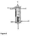
- the cartridge used as a hemodialysis cartridge for removing urea from the blood simply comprises a holding compartment ( Figure-2-1- and Figure-3-1); and because of the electrodes placed in the cartridge, ( Figure-2-A and B; Figure-3-A and B) electric current can be applied and that, it is also designed for the use of classical hemodialysis cartridge.
- the point labeled as 1 indicates the entry of blood and the label 2 shows the exit of the blood.
- the labels 3 a nd 4 show the entry and exit points of the hemodialysis solution.
- the label 5 shows the hemodialysis cartridge's dialysis membrane.
- the label B shows positive electrode, and label A represents the negative electrode.
- composition of the sterilized electrodes ( Figure-2-A and B; Figure-3-A and B) is preferred to be Ag/AgCl for preventing the pH effect of the electrodes, they can be also made out of platinum, copper, gold, steel, graphite, vanadium, tungsten, etc.
- the composition, shape, design, connection point and their place in and outside of the cartridge, are not deterministic and specific properties for the electrodes.
- the sodium and potassium levels of the blood and the hemodialysis solutions have been analyzed.
- the level of sodium and potassium is lowered in blood as well. This outcome is possibly same for some other ions and unchanged molecules.
- the ions and other material in the hemodialysis solution need to be adjusted.
- Hemodialysis solutions must be prepared according to the patients' needs. Or, the blood that exited from the hemodialysis cartridge can be connected to another cartridge and similarly ions can be replaced using reverse current and the problem can be solved.
- the hemodialysis solution(s) (at the beginning and at the supplementary durations) can be prepared according to the needed requirements of the patient to avoid any possible complications.
- This invention in addition to its speed and quality in the treatment of uremia, it has a high potential of removing unwanted/unneeded non-polar and especially polar substances during the acute and chronic poisoning; similarly with electrical current and the cartridge usage the unwanted items/substances in the blood can be pulled out into the hemodialysis solution.
- the electrical current lesser than 0.5 m A/cm 2 d oes n ot cause damage to the blood or body cells 1 . For this reason the current that is low than 0.5 mA/cm 2 would be an acceptable for a positive out come.
- the magnitude of the current can be chosen in required levels. For the system, direct or alternative current, square, sinus or triangular or even different frequencies and/or currencies can be applied.
- Electrodes can be made with different compounds or also some similar apparatuses with similar functions can be used.
- the electrodes may even be simply attached to the classical hemodialysis cartridges' blood and hem-dialysis solution's entry ports ( Figure 3 ). If the available classical hemodialysis cartridge will be used, an alternative placement of the electrodes are shown in Figure 3 . In this model, the electrodes can be attached to blood entry port and hemodialysis solution part as in the previous cases, and the classical hemodialysis cartridge can be used with minimal modifications. (In this model, electrodes in different composition or some apparatus with similar functions can be used). The electrodes themselves need to be sterilized. In figure 3 , the labels 1,2,3,4 and 5 are the same labels as shown in Figure 2 .
- this invention will prevent those patients who have insufficient kidney functions being hooked up to a hemodialysis machine for a long time. It will provide for the urea, creatine, and some toxic compounds to exit the blood in a better way. Additionally, the procedure's potential of removing the unwanted elements from the patient's blood stream in acute and chronic poisonings will provides a very valuable device in the field of medicine.
- the cartridge being proposed in terms of shape and dimensions is very similar to those cartridges used in classical hemodialysis.
- the difference of the cartridge, such as surface area or its membrane with different pore sizes, alone is not a distinctive quantification of the proposed device for patent purposes.
- the sizes, compositions, or locations (such as one being by the blood inflow side and the other being by the dialysis side or the solution) of the electrodes and/or some apparatuses with similar functions do not restrict its applicability for patent rights.
- composition of the hemodialysis solution the properties of the dialysis membrane (color, texture, latex or biological tissue, pore size, selectivity, etc.), the way, the flow intensity and the direction of the blood, hemodialysis solution and the number of cartridge used connected before or after each other are not also deterministic and specific properties of the invention.
Landscapes
- Health & Medical Sciences (AREA)
- Urology & Nephrology (AREA)
- Engineering & Computer Science (AREA)
- Heart & Thoracic Surgery (AREA)
- Life Sciences & Earth Sciences (AREA)
- Chemical & Material Sciences (AREA)
- Emergency Medicine (AREA)
- Animal Behavior & Ethology (AREA)
- Hematology (AREA)
- Water Supply & Treatment (AREA)
- Veterinary Medicine (AREA)
- Vascular Medicine (AREA)
- Anesthesiology (AREA)
- Biomedical Technology (AREA)
- Chemical Kinetics & Catalysis (AREA)
- Public Health (AREA)
- General Health & Medical Sciences (AREA)
- Electrochemistry (AREA)
- Environmental & Geological Engineering (AREA)
- Molecular Biology (AREA)
- External Artificial Organs (AREA)
- Separation Using Semi-Permeable Membranes (AREA)
- Pharmaceuticals Containing Other Organic And Inorganic Compounds (AREA)
Abstract
Description
- This invention is related to a cartridge that provides an additional step of iontophoresis to conventional/classic hemodialysis procedure for those patients who have insufficient kidney functions. It enhances the hemodialysis performance in removing of urea from the blood using electrical potentials. Similarly, it is also related with the procedures such as peritoneal dialysis or related with the procedure when some compounds or molecules (charged or uncharged atoms or molecules, elements or ions) need to be removed from the blood (blood, plasma or serum) to dialysis solution in acute or chronic poisoning cases. It is possible to increase the efficiency of the hemodialysis method and to reduce the total time period of the procedure using this proposed cartridge. There are no similar cartridges in use so far.
-
WO 00/38759 -
US 5437774 relates to a method that charged first molecular species is separated from a second molecular species by selectively passing one of the species through a separation membrane under the influence of an electrical potential. The separated species is maintained within a dialysate stream by retention membrane (or an electrode surface) adjacent the separation membrane. This method can not be applied during the dialysis and treatment of renal patients and also in the case of poisoning. - Basically, hemodialysis is a process to remove urea and some other toxic compounds from blood into the hemodialysis solution by passive diffusion. In this procedure, a semi-permeable membrane is used as a dialysis membrane. While the blood is circulating continuously at the one side of the hemodialysis membrane, the hemodialysis solution at the other side, continuously circulates as well. During the process, urea present in the blood at high concentration, depending on the concentration gradient, it passes through the membrane from blood to the hemodialysis solution. Thus, the urea concentration in blood decreases by the time, hi conventional hemodialysis procedures, the patient is connected to the hemodialysis machine for about 4 hours, and urea concentration generally decreases to 50% of the beginning level even at the best circumstances.
- In iontophoresis procedure, by using an electrical current (creating an electrical potential difference), the ions (molecules or atoms that having a net charge or partially charged) can be carried to the other side of the membrane according to applied current and electrical charge and it is possible to control it. Electrodes or similar tools are provided to the both side of the membrane and the applied electrical current or potential can vary as needed. The ions in the solution/blood migrate according to their charges and their movement is in proportional to the current. For instance positively charged ions migrate to the negative electrode side and vice versa. While the charged ions are migrating according to the electrical current, they also drag the uncharged can vary as needed. The ions in the solution/blood migrate according to their charges and their m ovement is in proportional to the current. For instance positively charged ions migrate to the negative electrode side and vice versa. While the charged ions are migrating according to the electrical current, they also drag the uncharged molecules along with moving molecules. At this instance, traveling from one side to the other side of the membrane creates a flow, a turbulence occurs (this is called an electro-osmotic flow).1 Therefore the unchanged particles (atoms/molecules) can also be able to pass through the membrane by being pulled into this vortex or into the motion and, this passage occurs at a much faster rate than that of passive diffusion.
- When the molecular structure of urea investigated, it is seen that some local charges are present on the molecule. According to the experiments we've conducted, the higher urea transportation was observed than passive diffusion and cathodal iontophoresis when urea was present at the positive electrode side because of the positive local charges on the molecule. There is also a possibility that the electroosmotic current was partially influential for this transfer. However, during the transfer, if the other small but charged ions like potassium and sodium are present, the transfer rate decreases; but still the transfer is much larger and faster than the classical method. These experiments were repeated using human blood obtained from the patients with uremia and similar results were achieved. With this invention the hemodialysis procedure is shortened in time and, simultaneously, provided much better result (cleaner blood).
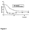
- The previously conducted diffusion experiments were repeated with a peristaltic pump using human blood, hemodialysis solution and the hemodialysis cartridge in new proposed design. In the analysis of the samples taken from the blood that went through the cartridge, it is found that the urea level in blood when the iontophoresis procedure was used prompted 3 to 5 times faster rate of decrease than the classical hemodialysis results. In other words, while the.classical hemodialysis procedure takes 4 hours, the iontophoresis procedure of ours lowers the process time to about 30 minutes, and with much better results (
Figure, 1 ). - If the classical hemodialysis cartridge and proposed iontophoresis procedure is going to be used together; system is depicted in
Figure 2 . The cartridge used as a hemodialysis cartridge for removing urea from the blood simply comprises a holding compartment (Figure-2-1- and Figure-3-1); and because of the electrodes placed in the cartridge, (Figure-2-A and B; Figure-3-A and B) electric current can be applied and that, it is also designed for the use of classical hemodialysis cartridge. - Accordingly, in this figure, the point labeled as 1 indicates the entry of blood and the
label 2 shows the exit of the blood. The labels 3 a nd 4 show the entry and exit points of the hemodialysis solution. Thelabel 5 shows the hemodialysis cartridge's dialysis membrane. The label B shows positive electrode, and label A represents the negative electrode. Thus, when the system is activated, the blood and hemodialysis solution is circulating continuously and electric current is applied and at the end urea can be transferred to the hemodialysis solution with much faster rate. The labels A and B are the electrodes made by Ag and AgCl or they can be designed for same purpose in different shape or compositions. If needed, it is possible to use Ag for B, and AgCl for A. UV or ethylene oxide sterilization can be used for the sterilization of the electrodes. - On the other hand, although the composition of the sterilized electrodes (Figure-2-A and B; Figure-3-A and B) is preferred to be Ag/AgCl for preventing the pH effect of the electrodes, they can be also made out of platinum, copper, gold, steel, graphite, vanadium, tungsten, etc. The composition, shape, design, connection point and their place in and outside of the cartridge, are not deterministic and specific properties for the electrodes. Some apparatuses which can be used in formation of electrical gradient may be utilized.
- In the experiments, when the electrohemodialysis procedure was used, the sodium and potassium levels of the blood and the hemodialysis solutions have been analyzed. When this procedure used, the level of sodium and potassium is lowered in blood as well. This outcome is possibly same for some other ions and unchanged molecules. For preventing some possible complications, the ions and other material in the hemodialysis solution need to be adjusted. Hemodialysis solutions must be prepared according to the patients' needs. Or, the blood that exited from the hemodialysis cartridge can be connected to another cartridge and similarly ions can be replaced using reverse current and the problem can be solved. The hemodialysis solution(s) (at the beginning and at the supplementary durations) can be prepared according to the needed requirements of the patient to avoid any possible complications.
- Additionally, in these complications (the problems like imbalance of electrolytes and/or osmotic pressure or similar unwanted outcomes due to iontophoresis) problems can be overcame by producing a membrane that would have smaller pores. With two membranes present in one, first one allows the unwanted urea and the other molecules does not allowed by second material to go through. The application of electrical current to both membrane or by applying the classical methods to the second one (utilizing only the concentration gradient) the possible problems can be avoided.
- There is no research and experiments that have been published so far, the application of electrical current or potential and the gradual electrical effect have not been tried for the hemodialysis or peritoneal dialysis or removing unwanted molecules, ions etc. f rom the blood or other body fluid using a system like our proposed system here. In this study, the addition of iontophoresis procedure, in terms of shortening the time duration and bettering the quality of outcome, is a revolutionary format that is at the cutting edge of the known medical technology. In the literature there is no study or research have been conducted to this end.
- This invention, in addition to its speed and quality in the treatment of uremia, it has a high potential of removing unwanted/unneeded non-polar and especially polar substances during the acute and chronic poisoning; similarly with electrical current and the cartridge usage the unwanted items/substances in the blood can be pulled out into the hemodialysis solution. In the literature we came across that the electrical current lesser than 0.5 m A/cm2 d oes n ot cause damage to the blood or body cells1. For this reason the current that is low than 0.5 mA/cm2 would be an acceptable for a positive out come. The magnitude of the current can be chosen in required levels. For the system, direct or alternative current, square, sinus or triangular or even different frequencies and/or currencies can be applied. In this system, the electrical flow/current does not make any direct contact with any of the body cells; and therefore, it would be possible to exceed the electrical level of the aforementioned literature. However, because there is a likelihood of damaging the blood cells during a high currency flow this would not be recommended.
- Additionally, the pH levels was not affected by the Ag/AgCl electrodes, therefore we preferred. Electrodes can be made with different compounds or also some similar apparatuses with similar functions can be used. The electrodes may even be simply attached to the classical hemodialysis cartridges' blood and hem-dialysis solution's entry ports (
Figure 3 ). If the available classical hemodialysis cartridge will be used, an alternative placement of the electrodes are shown inFigure 3 . In this model, the electrodes can be attached to blood entry port and hemodialysis solution part as in the previous cases, and the classical hemodialysis cartridge can be used with minimal modifications. (In this model, electrodes in different composition or some apparatus with similar functions can be used). The electrodes themselves need to be sterilized. Infigure 3 , thelabels Figure 2 . - As a result, this invention will prevent those patients who have insufficient kidney functions being hooked up to a hemodialysis machine for a long time. It will provide for the urea, creatine, and some toxic compounds to exit the blood in a better way. Additionally, the procedure's potential of removing the unwanted elements from the patient's blood stream in acute and chronic poisonings will provides a very valuable device in the field of medicine.
- With the exception of electrodes and similar apparatuses, the cartridge being proposed, in terms of shape and dimensions is very similar to those cartridges used in classical hemodialysis. The difference of the cartridge, such as surface area or its membrane with different pore sizes, alone is not a distinctive quantification of the proposed device for patent purposes. The sizes, compositions, or locations (such as one being by the blood inflow side and the other being by the dialysis side or the solution) of the electrodes and/or some apparatuses with similar functions do not restrict its applicability for patent rights.
- Additionally, the composition of the hemodialysis solution, the properties of the dialysis membrane (color, texture, latex or biological tissue, pore size, selectivity, etc.), the way, the flow intensity and the direction of the blood, hemodialysis solution and the number of cartridge used connected before or after each other are not also deterministic and specific properties of the invention.
-
- 1-M. J. Pikal, "The role of electro-osmotic flow in transdermal iontophoresis," Advanced Drug Delivery Reviews, 46, 281-305,2001.
Claims (6)
- An electrohemodialysis cartridge for enabling molecule or substance transfer between blood/plasma and a hemodialysis solution with a content prepared according to a patient's needs, said cartridge having
a membrane (5),
a blood compartment in which blood/plasma is circulated,
a hemodialysis solution compartment in which a hemodialysis solution is circulated, said blood/plasma compartment being separate from said hemodialysis solution compartment, characterized in that said cartridge further comprises one of the following;(i) an electrode positioned within said blood/plasma compartment and an oppositely charged electrode positioned within said hemodialysis solution compartment.(ii) an electrode positioned at the inlet of said blood/plasma compartment and an oppositely charged electrode positioned at the outlet of said hemodialysis solution compartment.(iii) an electrode positioned at the inlet of said blood/plasma compartment and an oppositely charged electrode positioned at the inlet of said hemodialysis solution compartment. - An electrohemodialysis cartridge according to Claim 1 characterized in that said electrodes (A,B) are made of a material selected from the group consisting of Ag, AgCl, platinum, copper, gold, steel, graphite, vanadium and tungsten.
- An electrohemodialysis cartridge according to Claim 1 characterized in that the electrode positioned in said blood/plasma compartment is an Ag electrode and that that positioned in the hemodialysis solution compartment is an AgCl electrode.
- An electrohemodialysis cartridge according to Claim 1 characterized in that it further comprises a further membrane with pores smaller than membrane (5) for preventing some necessary ions and uncharged molecules apart from the urea from flowing to the hemodialysis solution.
- An electrohemodialysis cartridge according to Claim 1 characterized in that positively charged electrode (B) is placed in the solution compartment and negatively charged electrode (A) is placed in blood/plasma compartment for removing other charged or uncharged atoms or molecules from the blood.
- An electrohemodialysis cartridge according to Claim 1 characterized in that said cartridge is configured to operate at a current less than 0.5 mA/cm2 on the electrodes (A and B).
Applications Claiming Priority (3)
| Application Number | Priority Date | Filing Date | Title |
|---|---|---|---|
| TR2001/03317A TR200103317A2 (en) | 2001-11-19 | 2001-11-19 | Electrohemodialysis cartridge. |
| TR200103317 | 2001-11-19 | ||
| PCT/TR2002/000073 WO2003043681A1 (en) | 2001-11-19 | 2002-11-19 | A cartridge for electrohemodialysis |
Publications (2)
| Publication Number | Publication Date |
|---|---|
| EP1511525A1 EP1511525A1 (en) | 2005-03-09 |
| EP1511525B1 true EP1511525B1 (en) | 2012-06-27 |
Family
ID=21623495
Family Applications (1)
| Application Number | Title | Priority Date | Filing Date |
|---|---|---|---|
| EP02795474A Expired - Lifetime EP1511525B1 (en) | 2001-11-19 | 2002-11-19 | A cartridge for electrohemodialysis |
Country Status (8)
| Country | Link |
|---|---|
| US (1) | US8057680B2 (en) |
| EP (1) | EP1511525B1 (en) |
| JP (1) | JP2005509498A (en) |
| CN (1) | CN100518837C (en) |
| AU (1) | AU2002360237A1 (en) |
| RU (1) | RU2323015C2 (en) |
| TR (2) | TR200103317A2 (en) |
| WO (1) | WO2003043681A1 (en) |
Families Citing this family (5)
| Publication number | Priority date | Publication date | Assignee | Title |
|---|---|---|---|---|
| KR101227453B1 (en) * | 2010-07-29 | 2013-01-29 | 서강대학교산학협력단 | Artificial nephron device |
| KR101698390B1 (en) * | 2013-12-17 | 2017-01-20 | 한국전자통신연구원 | Continous Recycle Typed Dialysis System for Portable Artifical Kidney |
| CN105771011A (en) * | 2016-01-31 | 2016-07-20 | 陈雯 | Nephritis treatment periodic dialysis apparatus |
| WO2018049333A1 (en) * | 2016-09-09 | 2018-03-15 | The Board Of Trustees Of The University Of Arkansas | Medical implants powered by reverse electrodialysis |
| US10933184B2 (en) * | 2016-09-30 | 2021-03-02 | Us Kidney Research Corporation | Dialysate free artificial kidney device |
Family Cites Families (17)
| Publication number | Priority date | Publication date | Assignee | Title |
|---|---|---|---|---|
| US2251083A (en) * | 1936-09-24 | 1941-07-29 | Theorell Axel Hugo Teodor | Method of and apparatus for separating crystalloids from accompanying substances |
| NL96474C (en) * | 1949-07-09 | |||
| US3582488A (en) * | 1965-06-25 | 1971-06-01 | Rashid A Zeineh | Method and apparatus for buffering,dialysis and concentrating biological fluid specimens |
| FR2043917A5 (en) * | 1969-05-02 | 1971-02-19 | Electronique Appliquee | Uniform porosity membranes for artificial - kidney or lung machines |
| US4043895A (en) * | 1973-05-16 | 1977-08-23 | The Dow Chemical Company | Electrophoresis apparatus |
| US4351710A (en) * | 1980-01-10 | 1982-09-28 | Ionics, Incorporated | Fractionation of protein mixtures |
| US4461693A (en) * | 1982-07-06 | 1984-07-24 | Ionics Incorporated | Polarity reversal electrodes |
| FR2538551B1 (en) * | 1982-12-27 | 1988-11-10 | Asahi Chemical Ind | METHOD AND INSTALLATION FOR DEHYDRATION OF A SUBSTANCE CONTAINING WATER BY ELECTRO-OSMOSIS |
| FR2568485B1 (en) * | 1984-08-06 | 1990-03-23 | Rhone Poulenc Rech | PROTEIN-CONTAINING ELECTROPHORESIS APPARATUS FOR USE, IN PARTICULAR FOR FRACTIONATION OF HUMAN PLASMA |
| US5135477A (en) * | 1984-10-29 | 1992-08-04 | Medtronic, Inc. | Iontophoretic drug delivery |
| US4608140A (en) * | 1985-06-10 | 1986-08-26 | Ionics, Incorporated | Electrodialysis apparatus and process |
| US5437774A (en) * | 1993-12-30 | 1995-08-01 | Zymogenetics, Inc. | High molecular weight electrodialysis |
| US5639368A (en) * | 1994-03-16 | 1997-06-17 | Davis; Dennis W. | Capillary membrane device |
| US6226830B1 (en) | 1997-08-20 | 2001-05-08 | Philips Electronics North America Corp. | Vacuum cleaner with obstacle avoidance |
| CA2332112C (en) | 1998-05-13 | 2004-02-10 | Cygnus, Inc. | Monitoring of physiological analytes |
| AUPP790898A0 (en) * | 1998-12-23 | 1999-01-28 | Life Therapeutics Limited | Renal dialysis |
| US20030065285A1 (en) | 2001-07-23 | 2003-04-03 | Higuchi William I. | Method and apparatus for increasing flux during reverse iontophoresis |
-
2001
- 2001-11-19 TR TR2001/03317A patent/TR200103317A2/en unknown
-
2002
- 2002-11-19 TR TR2004/01118T patent/TR200401118T2/en unknown
- 2002-11-19 CN CNB028269098A patent/CN100518837C/en not_active Expired - Fee Related
- 2002-11-19 AU AU2002360237A patent/AU2002360237A1/en not_active Abandoned
- 2002-11-19 WO PCT/TR2002/000073 patent/WO2003043681A1/en active Search and Examination
- 2002-11-19 US US10/496,053 patent/US8057680B2/en not_active Expired - Fee Related
- 2002-11-19 RU RU2004117911/14A patent/RU2323015C2/en not_active IP Right Cessation
- 2002-11-19 JP JP2003545359A patent/JP2005509498A/en active Pending
- 2002-11-19 EP EP02795474A patent/EP1511525B1/en not_active Expired - Lifetime
Also Published As
| Publication number | Publication date |
|---|---|
| US20050034991A1 (en) | 2005-02-17 |
| TR200401118T2 (en) | 2004-09-21 |
| EP1511525A1 (en) | 2005-03-09 |
| TR200103317A2 (en) | 2004-02-23 |
| US8057680B2 (en) | 2011-11-15 |
| JP2005509498A (en) | 2005-04-14 |
| RU2004117911A (en) | 2005-05-27 |
| WO2003043681A1 (en) | 2003-05-30 |
| CN100518837C (en) | 2009-07-29 |
| AU2002360237A1 (en) | 2003-06-10 |
| RU2323015C2 (en) | 2008-04-27 |
| CN1612757A (en) | 2005-05-04 |
Similar Documents
| Publication | Publication Date | Title |
|---|---|---|
| EP2019658B1 (en) | Method of microfluidic membraneless exchange in an h-filter and filtration of the extraction fluid outlet streams | |
| EP2214751B1 (en) | Method and device for differentiation of substances | |
| US20050133448A1 (en) | Shear-enhanced systems and methods for removing waste materials and liquid from the blood | |
| DE102011008329B4 (en) | Blood treatment unit for an extracorporeal blood treatment device | |
| US20130102948A1 (en) | Portable blood filtration devices, systems, and methods | |
| JP2011514182A (en) | Fluid separation apparatus, system, and method | |
| US20040238445A1 (en) | Vortex-enhanced filtration devices | |
| EP1511525B1 (en) | A cartridge for electrohemodialysis | |
| US5679231A (en) | Gel bed dialyzer | |
| US20190125951A1 (en) | Electrokinetic route to a wearable device for kidney disease management | |
| CN209052516U (en) | A kind of water treatment facilities for family hemodialysis instrument | |
| US9737653B2 (en) | Selective ultrafiltration membranes for renal replacement therapies | |
| EP0112094B1 (en) | Apparatus for blood treatment | |
| US9757504B2 (en) | Systems and methods for performing hemodialysis | |
| DE10157569A1 (en) | Blood purification system comprises micro-particle adsorbent contained in air-free flexible reservoir | |
| WO2023107019A1 (en) | A hemodialyzer with enhanced filtration performance | |
| CN110769920B (en) | System and method for filtering and/or diluting a fluid | |
| CN109095671A (en) | A kind of water treatment facilities for family hemodialysis instrument | |
| JPS5867261A (en) | Apparatus for purifying body liquid | |
| CH711293A2 (en) | dialysis device. | |
| JPH114889A (en) | Treating system of sanguineous propagative virus infectious disease or the like such as aids and hepatitis |
Legal Events
| Date | Code | Title | Description |
|---|---|---|---|
| PUAI | Public reference made under article 153(3) epc to a published international application that has entered the european phase |
Free format text: ORIGINAL CODE: 0009012 |
|
| 17P | Request for examination filed |
Effective date: 20041006 |
|
| AK | Designated contracting states |
Kind code of ref document: A1 Designated state(s): AT BE BG CH CY CZ DE DK EE ES FI FR GB GR IE IT LI LU MC NL PT SE SK TR |
|
| RAP1 | Party data changed (applicant data changed or rights of an application transferred) |
Owner name: DIZAYN TEKNIK PLASTIK BORU VE ELEMANLARI SAN. VE T |
|
| RIN1 | Information on inventor provided before grant (corrected) |
Inventor name: DEGIM, Y. TUNCER Inventor name: ILBASMIS, SIBEL Inventor name: OCZELIKAY, A. TANJU Inventor name: DEGIN, ZELIHAGUEL Inventor name: DENLI, METIN Inventor name: DUNDAROZ, RUSEN |
|
| 17Q | First examination report despatched |
Effective date: 20060904 |
|
| GRAP | Despatch of communication of intention to grant a patent |
Free format text: ORIGINAL CODE: EPIDOSNIGR1 |
|
| GRAS | Grant fee paid |
Free format text: ORIGINAL CODE: EPIDOSNIGR3 |
|
| GRAA | (expected) grant |
Free format text: ORIGINAL CODE: 0009210 |
|
| AK | Designated contracting states |
Kind code of ref document: B1 Designated state(s): AT BE BG CH CY CZ DE DK EE ES FI FR GB GR IE IT LI LU MC NL PT SE SK TR |
|
| REG | Reference to a national code |
Ref country code: GB Ref legal event code: FG4D |
|
| REG | Reference to a national code |
Ref country code: CH Ref legal event code: EP |
|
| REG | Reference to a national code |
Ref country code: AT Ref legal event code: REF Ref document number: 563795 Country of ref document: AT Kind code of ref document: T Effective date: 20120715 |
|
| REG | Reference to a national code |
Ref country code: IE Ref legal event code: FG4D |
|
| REG | Reference to a national code |
Ref country code: DE Ref legal event code: R096 Ref document number: 60243229 Country of ref document: DE Effective date: 20120823 |
|
| PG25 | Lapsed in a contracting state [announced via postgrant information from national office to epo] |
Ref country code: FI Free format text: LAPSE BECAUSE OF FAILURE TO SUBMIT A TRANSLATION OF THE DESCRIPTION OR TO PAY THE FEE WITHIN THE PRESCRIBED TIME-LIMIT Effective date: 20120627 Ref country code: SE Free format text: LAPSE BECAUSE OF FAILURE TO SUBMIT A TRANSLATION OF THE DESCRIPTION OR TO PAY THE FEE WITHIN THE PRESCRIBED TIME-LIMIT Effective date: 20120627 |
|
| REG | Reference to a national code |
Ref country code: NL Ref legal event code: VDEP Effective date: 20120627 |
|
| REG | Reference to a national code |
Ref country code: AT Ref legal event code: MK05 Ref document number: 563795 Country of ref document: AT Kind code of ref document: T Effective date: 20120627 |
|
| PG25 | Lapsed in a contracting state [announced via postgrant information from national office to epo] |
Ref country code: GR Free format text: LAPSE BECAUSE OF FAILURE TO SUBMIT A TRANSLATION OF THE DESCRIPTION OR TO PAY THE FEE WITHIN THE PRESCRIBED TIME-LIMIT Effective date: 20120928 |
|
| PG25 | Lapsed in a contracting state [announced via postgrant information from national office to epo] |
Ref country code: CY Free format text: LAPSE BECAUSE OF FAILURE TO SUBMIT A TRANSLATION OF THE DESCRIPTION OR TO PAY THE FEE WITHIN THE PRESCRIBED TIME-LIMIT Effective date: 20120627 Ref country code: BE Free format text: LAPSE BECAUSE OF FAILURE TO SUBMIT A TRANSLATION OF THE DESCRIPTION OR TO PAY THE FEE WITHIN THE PRESCRIBED TIME-LIMIT Effective date: 20120627 Ref country code: EE Free format text: LAPSE BECAUSE OF FAILURE TO SUBMIT A TRANSLATION OF THE DESCRIPTION OR TO PAY THE FEE WITHIN THE PRESCRIBED TIME-LIMIT Effective date: 20120627 Ref country code: SK Free format text: LAPSE BECAUSE OF FAILURE TO SUBMIT A TRANSLATION OF THE DESCRIPTION OR TO PAY THE FEE WITHIN THE PRESCRIBED TIME-LIMIT Effective date: 20120627 Ref country code: AT Free format text: LAPSE BECAUSE OF FAILURE TO SUBMIT A TRANSLATION OF THE DESCRIPTION OR TO PAY THE FEE WITHIN THE PRESCRIBED TIME-LIMIT Effective date: 20120627 Ref country code: CZ Free format text: LAPSE BECAUSE OF FAILURE TO SUBMIT A TRANSLATION OF THE DESCRIPTION OR TO PAY THE FEE WITHIN THE PRESCRIBED TIME-LIMIT Effective date: 20120627 |
|
| PG25 | Lapsed in a contracting state [announced via postgrant information from national office to epo] |
Ref country code: IT Free format text: LAPSE BECAUSE OF FAILURE TO SUBMIT A TRANSLATION OF THE DESCRIPTION OR TO PAY THE FEE WITHIN THE PRESCRIBED TIME-LIMIT Effective date: 20120627 Ref country code: PT Free format text: LAPSE BECAUSE OF FAILURE TO SUBMIT A TRANSLATION OF THE DESCRIPTION OR TO PAY THE FEE WITHIN THE PRESCRIBED TIME-LIMIT Effective date: 20121029 |
|
| PG25 | Lapsed in a contracting state [announced via postgrant information from national office to epo] |
Ref country code: NL Free format text: LAPSE BECAUSE OF FAILURE TO SUBMIT A TRANSLATION OF THE DESCRIPTION OR TO PAY THE FEE WITHIN THE PRESCRIBED TIME-LIMIT Effective date: 20120627 |
|
| PG25 | Lapsed in a contracting state [announced via postgrant information from national office to epo] |
Ref country code: ES Free format text: LAPSE BECAUSE OF FAILURE TO SUBMIT A TRANSLATION OF THE DESCRIPTION OR TO PAY THE FEE WITHIN THE PRESCRIBED TIME-LIMIT Effective date: 20121008 Ref country code: DK Free format text: LAPSE BECAUSE OF FAILURE TO SUBMIT A TRANSLATION OF THE DESCRIPTION OR TO PAY THE FEE WITHIN THE PRESCRIBED TIME-LIMIT Effective date: 20120627 |
|
| PLBE | No opposition filed within time limit |
Free format text: ORIGINAL CODE: 0009261 |
|
| STAA | Information on the status of an ep patent application or granted ep patent |
Free format text: STATUS: NO OPPOSITION FILED WITHIN TIME LIMIT |
|
| 26N | No opposition filed |
Effective date: 20130328 |
|
| REG | Reference to a national code |
Ref country code: CH Ref legal event code: PL |
|
| REG | Reference to a national code |
Ref country code: DE Ref legal event code: R097 Ref document number: 60243229 Country of ref document: DE Effective date: 20130328 |
|
| PG25 | Lapsed in a contracting state [announced via postgrant information from national office to epo] |
Ref country code: LI Free format text: LAPSE BECAUSE OF NON-PAYMENT OF DUE FEES Effective date: 20121130 Ref country code: BG Free format text: LAPSE BECAUSE OF FAILURE TO SUBMIT A TRANSLATION OF THE DESCRIPTION OR TO PAY THE FEE WITHIN THE PRESCRIBED TIME-LIMIT Effective date: 20120927 Ref country code: CH Free format text: LAPSE BECAUSE OF NON-PAYMENT OF DUE FEES Effective date: 20121130 |
|
| REG | Reference to a national code |
Ref country code: IE Ref legal event code: MM4A |
|
| PG25 | Lapsed in a contracting state [announced via postgrant information from national office to epo] |
Ref country code: IE Free format text: LAPSE BECAUSE OF NON-PAYMENT OF DUE FEES Effective date: 20121119 |
|
| PG25 | Lapsed in a contracting state [announced via postgrant information from national office to epo] |
Ref country code: MC Free format text: LAPSE BECAUSE OF NON-PAYMENT OF DUE FEES Effective date: 20121130 |
|
| PG25 | Lapsed in a contracting state [announced via postgrant information from national office to epo] |
Ref country code: LU Free format text: LAPSE BECAUSE OF NON-PAYMENT OF DUE FEES Effective date: 20121119 |
|
| REG | Reference to a national code |
Ref country code: FR Ref legal event code: PLFP Year of fee payment: 14 |
|
| PGFP | Annual fee paid to national office [announced via postgrant information from national office to epo] |
Ref country code: GB Payment date: 20151123 Year of fee payment: 14 Ref country code: DE Payment date: 20151117 Year of fee payment: 14 |
|
| PGFP | Annual fee paid to national office [announced via postgrant information from national office to epo] |
Ref country code: FR Payment date: 20151130 Year of fee payment: 14 |
|
| PGFP | Annual fee paid to national office [announced via postgrant information from national office to epo] |
Ref country code: TR Payment date: 20161121 Year of fee payment: 15 |
|
| REG | Reference to a national code |
Ref country code: DE Ref legal event code: R119 Ref document number: 60243229 Country of ref document: DE |
|
| GBPC | Gb: european patent ceased through non-payment of renewal fee |
Effective date: 20161119 |
|
| REG | Reference to a national code |
Ref country code: FR Ref legal event code: ST Effective date: 20170731 |
|
| PG25 | Lapsed in a contracting state [announced via postgrant information from national office to epo] |
Ref country code: FR Free format text: LAPSE BECAUSE OF NON-PAYMENT OF DUE FEES Effective date: 20161130 |
|
| PG25 | Lapsed in a contracting state [announced via postgrant information from national office to epo] |
Ref country code: GB Free format text: LAPSE BECAUSE OF NON-PAYMENT OF DUE FEES Effective date: 20161119 Ref country code: DE Free format text: LAPSE BECAUSE OF NON-PAYMENT OF DUE FEES Effective date: 20170601 |