EP1511409B1 - Schlagstockhalter - Google Patents
Schlagstockhalter Download PDFInfo
- Publication number
- EP1511409B1 EP1511409B1 EP03730926A EP03730926A EP1511409B1 EP 1511409 B1 EP1511409 B1 EP 1511409B1 EP 03730926 A EP03730926 A EP 03730926A EP 03730926 A EP03730926 A EP 03730926A EP 1511409 B1 EP1511409 B1 EP 1511409B1
- Authority
- EP
- European Patent Office
- Prior art keywords
- baton
- holding member
- holder
- bracket
- strap
- Prior art date
- Legal status (The legal status is an assumption and is not a legal conclusion. Google has not performed a legal analysis and makes no representation as to the accuracy of the status listed.)
- Expired - Lifetime
Links
Images
Classifications
-
- F—MECHANICAL ENGINEERING; LIGHTING; HEATING; WEAPONS; BLASTING
- F41—WEAPONS
- F41C—SMALLARMS, e.g. PISTOLS, RIFLES; ACCESSORIES THEREFOR
- F41C33/00—Means for wearing or carrying smallarms
- F41C33/02—Holsters, i.e. cases for pistols having means for being carried or worn, e.g. at the belt or under the arm
-
- A—HUMAN NECESSITIES
- A45—HAND OR TRAVELLING ARTICLES
- A45F—TRAVELLING OR CAMP EQUIPMENT: SACKS OR PACKS CARRIED ON THE BODY
- A45F5/00—Holders or carriers for hand articles; Holders or carriers for use while travelling or camping
-
- A—HUMAN NECESSITIES
- A45—HAND OR TRAVELLING ARTICLES
- A45F—TRAVELLING OR CAMP EQUIPMENT: SACKS OR PACKS CARRIED ON THE BODY
- A45F5/00—Holders or carriers for hand articles; Holders or carriers for use while travelling or camping
- A45F5/02—Fastening articles to the garment
- A45F5/021—Fastening articles to the garment to the belt
-
- A—HUMAN NECESSITIES
- A45—HAND OR TRAVELLING ARTICLES
- A45F—TRAVELLING OR CAMP EQUIPMENT: SACKS OR PACKS CARRIED ON THE BODY
- A45F5/00—Holders or carriers for hand articles; Holders or carriers for use while travelling or camping
- A45F5/1566—Holders or carriers for tubular, rod-shaped articles, e.g. batons
Definitions
- the present invention concerns a baton holder for carrying a baton in a belt, a strap or the like.
- the invention particularly concerns a baton holder for telescopic batons.
- the holders for baton traditionally used by the police force are shaped similar to knife scabbard, suspended from a belt.
- the holders comprise two connected parts that are pivotally attached to each other around a substantially horizontal axis, holding the two parts in certain predetermined fixed relative positions (click-stop function).
- a first part of the baton holder is intended to be attached to the user's belt and will under use be substantially immovably attached to the belt, while the second part, which is designed to envelop parts of the baton, is pivotally attached to said first part.
- WO 01/30611 A1 describes a baton holder for carrying a baton horizontally. Unwanted axial movement of the baton is safeguarded by the provision of a laterally extending member (6) that through a rotation of the baton, slides into a corresponding transverse recess in the holder thereby locking the member 6 in said recess.
- the baton holder according to this publication is, however, not useful for batons without such a lateral extending member.
- US 495 5518 relates to a baton holder for carrying the baton in a position in which the axis of the baton is mainly perpendicular to the axis of the belt which carries the baton holder. Furthermore, the baton holder of US 495 5518 has first and second holding members which are held together on a common bracket and therefore do not provide adjustment of the distance between the two holders.
- the baton holder comprises two holding members attached to the user's belt so that the baton may be carried in a position parallel to the belt at all times.
- the baton holder is carried on a regular belt but may also be carried on a belt carried diagonally across the user's torso or substantially parallel with an upper arm.
- the holder may also be arranged on a comparatively rigid support structure intended to be carried on the user's thigh, preferably with its upper end suspended from a regular belt over a connective member. In such a case there will be a joint between the connective member suspended from the belt and the rigid support structure attached to the users thigh.
- the first holding member is designed to envelop the baton in such a way that its grip end is free.
- Most telescopic batons do not have a particularly designed "grip", but are intended to be held at one end while the other end is extendable.
- the entire outermost element of such a baton has a substantially constant diameter and normally a uniform type of surface, not providing any distinct border between its grip end and the rest of the baton.
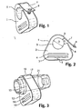
- the first holding member 1 comprises a bracket 2 with two slit shaped openings 3, 4 therethrough for a belt and with a circular opening 5 to surround the baton in the region close to its grip (end).
- the diameter D of the opening 5 therefore generally corresponds to the outer diameter of the baton.
- the bracket 2 is not fully closed around the opening 5 but has a gap 6 in one region.
- the bracket 2 is preferably made in a very durable natural or synthetic rubber material that exhibits a generally high friction contact with the baton and against the user's belt received by opening 3.
- the opening 4 is intended to receive the free end of the belt outside the belt buckle, and in this opening a high friction contact with the belt is not desired.
- the opening 4 is therefor generally made somewhat wider than opening 3 and possibly with another surface treatment.
- a strap 7 the ends of which are attached to mutually corresponding parts of a snap fastener 8.
- Other embodiments of the invention may include locking devices other than a snap fastener for the strap 7.
- the gap 6 in the bracket 2 has, in an unconstrained condition, a width G (gap).
- the strap 7 is so dimensioned that when the snap fastener is closed, the bracket 2 becomes somewhat compressed, thus the width G is somewhat reduced. This leads to a marginal reduction in the effective diameter D of the circular opening 5.
- the baton (not shown) becomes effectively held tightly by the bracket 2 that already has a comparatively high frictional contact with the baton due to the inherent properties of the material chosen for this component.
- the strap 7 may be shaped as a narrow extension of the bracket itself, so that the bracket and the strap may be shaped as one uniform piece. With respect to its manufacture this is simpler and more convenient than making the bracket and strap as separate units to thereafter be attached to each other, even though the latter solution has the advantage that the choice of material may be tailor-made for each of the components.
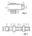
- Figs. 3 and 4 shows the second holding member 10 designed to be carried on the users belt at a distance from the first holding member 1 that is adapted to the passive baton length.
- passive baton length is meant the length of e.g. a telescopic baton when pushed completely together.
- the holding member 10 comprises a bracket 12 that has substantially the same shape as bracket 2. It differs from bracket 2 in that the opening 15 is formed with a diameter adapted to receive a separate bushing 21 with a longitudinal substantially cylindrical opening 22 whose diameter is slightly larger than the diameter of the baton at the end opposite to the grip end. The diameter of the opening 15 will thus normally be larger than the diameter D of opening 5 which in turn will be approximately the size of the diameter of the opening 22.
- the bracket 12 differs from bracket 2 also by the fact that it does not include any gap corresponding to gap 6 in bracket 2.
- the bracket 12 may be surrounded by a strap 17 or a reinforcement in a material that, similar to the strap 7, has a high tensile strength and supports the bracket 12 ensuring a thigh enveloping of the bushing 21.
- the reinforcement or the strap 17 does not need to be detachable and is therefore not provided with any snap fastener or the like.
- the bushing 21 is preferably made from a material that provides a low friction contact with the baton, at least with the chosen diameter of the opening 22 in the bushing.
- the opening 22 in the bushing 21 may, but need not, extend completely through the bushing 21.
- An alternative is an opening that narrows to a smaller diameter, so that the end of the baton will rest against a ring shaped shoulder 23, while an opening 24 with a smaller diameter than that of opening 22 ensures that moisture or dirt does not become trapped within the bushing.
- the bushing 21 is typically made in a hard plastic material that does not become brittle even at low temperatures.
- the slit shaped openings 3, 13 in the brackets 2 and 12 respectively will receive the closed part of the user's belt and should provide a high friction contact with the belt in order that the holding member 1 and 10 respectively is held at the same position at all times even when the user is active, e.g. runs, climbs, gets into and out of cars etc.
- the width of the openings 3, 13 therefor should be of the same dimension as the belt thickness, and the openings should preferably have a rough surface.
- the material thickness T (see Fig. 2 ) of the brackets 2, 12 between the openings 3, 13 and the users body contributes to stabilising the holding members.
- the openings 4, 14 in the bracket 2 and 12 respectively shall on the other hand receive the free end of the belt and there is thus no need for high friction contact between belt and bracket in these openings. To the contrary, high friction will represent a practical disadvantage in these latter openings.
- the openings 4, 14 generally have a width somewhat larger than the belt thickness, and the surface of the brackets within openings 4, 14 may be treated in a way that makes them smoother and less rough.
- FIG. 5 shows schematically how the baton holder, consisting of holding members 1 and 10, may be attached to a belt 31 with a baton 32 mounted to the holder.
- the baton 32 has a grip end 33 that is available and an end 34 that is at least partially covered by the bushing 21 of the holding member 10.
- the baton will normally be telescopically extendable at the end 34. From the belt buckle 35 and behind the baton the belt overlap, with the free end of the belt being received by the slit shaped opening 4 in bracket 2 and if necessary also by the slit shaped opening 14 in bracket 12. While the holding member 1 of Fig. 5 is shown with the free end of the strap 7 pointing upwards, the opposite orientation of holding member 1 is also possible.
- the illustrated embodiments of the invention intending to be attached to a common belt, assumes at least one and preferably two slit shaped openings (3, 4 and 13 , 14 respectively) in the brackets.
- the brackets may be attached to the structure by way of other means than such slit shaped openings;
- the baton could lay at the left side of the body.
- the user will let e.g. the four outermost fingers of his right hand bend around the grip end 33 while the thumb on same hand is positioned at the end of the strap 7 above the snap-fastener 8.
- the snap-fastener may be released with the thumb while the grip end of the baton is moved out of the holding member 1 through the gap 6 in bracket 2.
- the end 34 of the baton is released from the bushing 21 and is thereby completely free of the holding member 10,
- the baton may rapidly.be swung so that its end 34 points downwards.
- the same holding members are preferably mounted to the right of the belt buckle. With regular orientation of the belt, there is then no need for the openings 4 and 14 in the brackets. The operation will otherwise be similar with this positioning of the baton holder as the one described above.
- both holding members are attached at the same side of the belt buckle, it is further possible to attach one holding member to the right of the belt buckle and the other holding member to its left, in which case the baton in its passive position rests substantially in front of the belt buckle. It is also an option to carry the baton in a diagonal belt or strap across the users chest or in a kind of shoulder holster, that with respect to the language of this patent specification is to be considered as a belt.
- the first holding member will anyhow be the one closest to the grip end of the baton, i.e. the end of the baton that is intended to be held when the baton is to be used.
- the locking mechanism may be a miniature bar (not shown), e.g. 0.5 em high and somewhat extended at its outer end, that is attached to and extends out from the part of the strap that is fixed to the bracket 2 under the gap 6.
- the free end of the strap 7 that extends over the gap 6 from above is provided with a bole or a slit that fits snugly over the said extension on the miniature bar.
- the baton holder With respect to manufacturing technicalities, it is convenient to manufacture the baton holder as two separate elements and have the users belt ensure that they function as one unit. A minor change of the distance between the two holding members will not adversely impact on its use, partly due to the fact that the baton end 34 may frictionless move some centimetres back and forth within the bushing 21 with no risk of the baton slipping out of the holding member.
- a baton holder according to prior art with click-stop positions may also be used, although it does not constitute an optimal solution.
- the baton At the holding member 1 the baton will neither be able to rotate or to move axially, but will remain in position until the locking mechanism / the snap fastener is opened. Even following an unintentional opening of the locking mechanism (the snap-fastener 8) the baton will not, without assistance from a hand, be able to pass out through gap 6, as this in its unconstrained condition is significantly less than .the diameter of the baton.
- the holding member 10 shown in Figs. 3 and 4 appears is made up of two components, bracket 12 and bushing 21, while also the bracket may be enveloped by a third component in the form of a strap 17 or other reinforcing element. It is, however, fully consistent with the present invention that the entire holding member 10 is manufactured from one piece of a homogenous material. In such a case particular efforts may be required to ensure the desired low frictional contact with the baton and desired high frictional contact with the belt. This challenge may be met through a combination of optimal dimensioning of the openings 13 and 22 respectively and possibly by way of a surface treatment in one or both of said openings.
- the holding member 10 may also comprise more than the three shown components.
- the holding member 1 shown in Figs 1 and 2 may also be composed of more or fewer components than the ones shown in the drawings.
Landscapes
- General Engineering & Computer Science (AREA)
- Engineering & Computer Science (AREA)
- Buckles (AREA)
- Clamps And Clips (AREA)
- Accessories Of Cameras (AREA)
- Workshop Equipment, Work Benches, Supports, Or Storage Means (AREA)
- Eye Examination Apparatus (AREA)
- Polarising Elements (AREA)
- Transition And Organic Metals Composition Catalysts For Addition Polymerization (AREA)
- Ceramic Products (AREA)
- Basic Packing Technique (AREA)
- Lasers (AREA)
- Gyroscopes (AREA)
- Liquid Crystal Substances (AREA)
Claims (10)
- Ein Schlagstockhalter und ein Schlagstock, wobei der Schlagstockhalter zum Tragen des Schlagstocks (32) dient, der Schlagstockhalter an einem tragbaren länglichen Halteelement (31) anbringbar ist und der Schlagstockhalter umfaßt:ein erstes Halteelement (1), das ausgestaltet ist, den Schlagstock zum Griffende des Schlagstocks hin im wesentlichen so zu umgeben, so dass dessen Griffende (33) freiliegt, wobei das erste Halteelement (1) ein Material bildet oder umfasst, das flexibel ist und das eine Verriegelungseinrichtung (7,8) umfasst, das zum jeweiligen Schließen und Öffnen eines Zwischenraums (6) in dem ersten Halteelement (1) geeignet ist, wobei der Zwischenraum (6) zum Aufnehmen/Entnehmen des Schlagstocks (32) in/aus dem ersten Halteelement (1) dient, während das freie Griffende des Schlagstocks (32) gehalten wird, undeinem zweiten Halteelement (10), das ausgestaltet ist, den Schlagstock in einem Abstand weiter entfernt von dem Griffende (33) als das erste Halteelement (1) zu umgeben, wobei das zweite Halteelement (10) ein Material (21) mit einer Öffnung (22), welche einen marginal größeren Durchmesser als der des Endes des Schlagstocks, welches das zweite Halteelement (10) umgeben soll, bildet oder umfasst, wobei das erste und das zweite Halteelement (1 bzw. 10) die Form separater Komponenten mit jeweiligen Aufnahmeelementen (3,13) haben, die jeweils unabhängig die Befestigung an dem länglichen Halteelement (31) zulassen, so dass der Halter die Funktion einer einzelnen Einheit (1,31,10) einnimmt und die den Schlagstock (32) dauernd in einer Position halten, bei der die Longitudinalachse des Schlagstocks (32) hauptsächlich parallel zu dem länglichen Halteelement (31) ist,
dadurch gekennzeichnet, dass die Aufnahmeelemente (3,13) eine Einstellung des Abstands zwischen den Halteelementen (1,10) ermöglichen. - Der Halter und Schlagstock gemäß Anspruch 1, dadurch gekennzeichnet, dass die Verriegelungseinrichtung (7,8) eine Lasche (7) und einen Einrast-Befestiger (8) umfasst.
- Der Halter und Schlagstock gemäß Anspruch 1, dadurch gekennzeichnet, dass die Verriegelungseinrichtung eine Lasche (7) mit einer Öffnung nahe ihrem freien Ende sowie ein kurzer sich erstreckender Steg an dem gegenüberliegenden Ende aufweist.
- Der Halter und Schlagstock gemäß Anspruch 2 oder 3, dadurch gekennzeichnet, dass das erste Halteelement (1) eine Klammer (2) und eine Lasche (7) umfasst, wobei die Lasche (7) aus einem Material hergestellt ist, das sich von dem Material der Klammer (2) unterscheidet.
- Der Halter und Schlagstock gemäß Anspruch 2 oder 3, dadurch gekennzeichnet, dass das erste Halteelement (1) eine Klammer (2) und eine Lasche (7) umfasst, wobei die Lasche (7) aus dem selben Material wie die Klammer (2) hergestellt und als ein homogenes Teil mit der Klammer ausgebildet ist.
- Der Halter und Schlagstock gemäß einem der vorstehenden Ansprüche, dadurch gekennzeichnet, dass das Material für das erste Halteelement (1) eines ist, das einen vergleichsweise hohen Reibungskontakt mit dem Schlagstock (32) bietet und zum Beispiel ein natürliches oder synthetisches Gummimaterial umfasst.
- Der Halter und Schlagstock gemäß einem der vorstehenden Ansprüche, dadurch gekennzeichnet, dass das Material für das zweite Halteelement (1) eines ist, das in Kombination mit dem ausgewählten Durchmesser der Öffnung (22) einen vergleichsweise geringen Reibungskontakt mit dem Schlagstock (32) besitzt und zum Beispiel ein Kunststoffmaterial (21) aufweisen kann.
- Der Halter und Schlagstock gemäß einem der vorstehenden Ansprüche, dadurch gekennzeichnet, dass das erste Halteelement (1) geeignet ist, in einem Abstand von dem zweiten Halteelement (10) positioniert zu werden, welcher durch eine passiv zurückgezogene Länge eines Schlagstocks (32), welcher teleskopisch ist, vorgegeben ist.
- Der Halter und Schlagstock gemäß einem der vorstehenden Ansprüche, dadurch gekennzeichnet, dass das erste Halteelement (1) so angeordnet ist, dass es nahe an der Gürtelschließe eines normalen Gürtels anbringbar ist, während das zweite Halteelement (10) so angeordnet ist, dass es auf der selben Seite der Gürtelschließe (35) wie das erste Halteelement (1) oder an der gegenüberliegenden Seite der Gürtelschließe (35) im Vergleich zu dem ersten Halteelement (1) anbringbar ist.
- Der Halter und Schlagstock gemäß einem der Ansprüche 1 bis 8, dadurch gekennzeichnet, dass er so angeordnet ist, dass er an einer starren Haltestruktur anbringbar ist, welche an dem Oberschenkel eines Benutzers anzubringen ist.
Applications Claiming Priority (3)
| Application Number | Priority Date | Filing Date | Title |
|---|---|---|---|
| NO20022261A NO316195B1 (no) | 2002-05-13 | 2002-05-13 | Holder for batong |
| NO20022261 | 2002-05-13 | ||
| PCT/NO2003/000151 WO2003094661A1 (en) | 2002-05-13 | 2003-05-09 | Baton holder |
Publications (2)
| Publication Number | Publication Date |
|---|---|
| EP1511409A1 EP1511409A1 (de) | 2005-03-09 |
| EP1511409B1 true EP1511409B1 (de) | 2008-12-24 |
Family
ID=19913627
Family Applications (1)
| Application Number | Title | Priority Date | Filing Date |
|---|---|---|---|
| EP03730926A Expired - Lifetime EP1511409B1 (de) | 2002-05-13 | 2003-05-09 | Schlagstockhalter |
Country Status (8)
| Country | Link |
|---|---|
| US (1) | US20050205636A1 (de) |
| EP (1) | EP1511409B1 (de) |
| CN (1) | CN100421597C (de) |
| AT (1) | ATE418279T1 (de) |
| AU (1) | AU2003241225A1 (de) |
| DE (1) | DE60325471D1 (de) |
| NO (1) | NO316195B1 (de) |
| WO (1) | WO2003094661A1 (de) |
Families Citing this family (5)
| Publication number | Priority date | Publication date | Assignee | Title |
|---|---|---|---|---|
| ATE424543T1 (de) * | 2006-03-09 | 2009-03-15 | Bretislav Kostal | Schlagstockhalter |
| US20100001028A1 (en) * | 2008-07-01 | 2010-01-07 | Larry Titshaw | Waist mounted hose and cord puller |
| ITMC20090091A1 (it) * | 2009-04-23 | 2010-10-24 | Renato Tondi | Supporto per appendere una racchetta da tennis alla vita dell'utente. |
| US20150014375A1 (en) * | 2012-02-29 | 2015-01-15 | Trimble Navigation, Limited | Survey swing |
| CN105873471B (zh) | 2014-01-10 | 2018-01-02 | 菲斯科尔思品牌有限公司 | 用于刀鞘的可变的安装系统 |
Citations (1)
| Publication number | Priority date | Publication date | Assignee | Title |
|---|---|---|---|---|
| GB2352969A (en) * | 1999-08-05 | 2001-02-14 | Jeffrey Michael Harris | Hands free umbrella carrying device |
Family Cites Families (27)
| Publication number | Priority date | Publication date | Assignee | Title |
|---|---|---|---|---|
| US454770A (en) * | 1891-06-23 | Edgar robinson | ||
| US710236A (en) * | 1901-09-14 | 1902-09-30 | Francis H Audley | Holder for policemen's clubs. |
| US755009A (en) * | 1903-02-16 | 1904-03-22 | Augusta J Igel | Umbrella- carrier. |
| US3421632A (en) * | 1966-08-18 | 1969-01-14 | Francis E Wood | Rod-holding rack |
| FR2247925A5 (de) * | 1973-10-10 | 1975-05-09 | Itw De France | |
| US4006825A (en) * | 1975-03-17 | 1977-02-08 | Milton Austin | Novel fishing rod support |
| US3992799A (en) * | 1975-06-24 | 1976-11-23 | Oakes Duwayne E | Rod sections retaining socket & bracket |
| US4132381A (en) * | 1977-10-06 | 1979-01-02 | Mcclellan Industries, Inc. | Releasable clamp for elongated objects such as fishing rods |
| US4830247A (en) * | 1987-04-13 | 1989-05-16 | Steve Banks | Belt-suspended holster for caulking gun |
| US4751923A (en) * | 1987-06-02 | 1988-06-21 | Marino Michael P | Sling, shoulder immobilizer and posture corrector |
| US4863083A (en) * | 1988-06-08 | 1989-09-05 | Chen Carl W | Skis and boots carrying waist belt |
| US4871102A (en) * | 1988-11-09 | 1989-10-03 | Wickersham John M | Ski retaining device |
| US4955518A (en) * | 1989-03-31 | 1990-09-11 | Parsons Kevin L | Baton clip for expandable batons |
| US4953769A (en) * | 1989-03-31 | 1990-09-04 | Parsons Kevin L | Baton clip |
| US5086762A (en) * | 1991-03-15 | 1992-02-11 | Chee Edward K | Typing brace |
| US5232137A (en) * | 1992-01-13 | 1993-08-03 | Devine Mark E | Apparatus for carrying a spray can |
| US5449104A (en) * | 1994-03-23 | 1995-09-12 | Armament Systems & Procedures | Baton carrier for expandable batons |
| US5711468A (en) * | 1995-11-24 | 1998-01-27 | Shoemaker; Sharon L. | Baton holder flange |
| US5797670A (en) * | 1996-08-23 | 1998-08-25 | American Industrial Design Co., Inc. | Portable power tool light, accessory mounting belt, and method of using same |
| TR199901184T2 (xx) * | 1996-11-04 | 1999-08-23 | Rassias, John N | G�venlik ve yerle�tirme sistemi. |
| US5947352A (en) * | 1998-01-27 | 1999-09-07 | Armament Systems And Procedures, Inc. | Quick-release scabbard for batons |
| US6176403B1 (en) * | 1998-03-30 | 2001-01-23 | Zachary D. Svare | Sports utility belt |
| US6217072B1 (en) * | 1998-04-15 | 2001-04-17 | Jeffrey G. Gregg | Snowboard pole system |
| US6497349B1 (en) * | 2000-08-18 | 2002-12-24 | Leonard C. Ramirez | Support device for an elongated weapon |
| US6370810B1 (en) * | 2000-08-29 | 2002-04-16 | Scott Widerman | Fishing rod holder |
| US6435469B1 (en) * | 2001-01-19 | 2002-08-20 | William R. Ratcliff | Umbrella mount |
| US6695704B2 (en) * | 2001-11-08 | 2004-02-24 | Armament Systems And Procedures, Inc. | Tactical baton ankle scabbard |
-
2002
- 2002-05-13 NO NO20022261A patent/NO316195B1/no unknown
-
2003
- 2003-05-09 EP EP03730926A patent/EP1511409B1/de not_active Expired - Lifetime
- 2003-05-09 DE DE60325471T patent/DE60325471D1/de not_active Expired - Lifetime
- 2003-05-09 US US10/512,085 patent/US20050205636A1/en not_active Abandoned
- 2003-05-09 WO PCT/NO2003/000151 patent/WO2003094661A1/en not_active Ceased
- 2003-05-09 CN CNB038107449A patent/CN100421597C/zh not_active Expired - Fee Related
- 2003-05-09 AU AU2003241225A patent/AU2003241225A1/en not_active Abandoned
- 2003-05-09 AT AT03730926T patent/ATE418279T1/de not_active IP Right Cessation
Patent Citations (1)
| Publication number | Priority date | Publication date | Assignee | Title |
|---|---|---|---|---|
| GB2352969A (en) * | 1999-08-05 | 2001-02-14 | Jeffrey Michael Harris | Hands free umbrella carrying device |
Also Published As
| Publication number | Publication date |
|---|---|
| US20050205636A1 (en) | 2005-09-22 |
| DE60325471D1 (de) | 2009-02-05 |
| NO20022261L (no) | 2003-11-14 |
| CN100421597C (zh) | 2008-10-01 |
| ATE418279T1 (de) | 2009-01-15 |
| NO316195B1 (no) | 2003-12-22 |
| CN1652707A (zh) | 2005-08-10 |
| AU2003241225A1 (en) | 2003-11-11 |
| EP1511409A1 (de) | 2005-03-09 |
| NO20022261D0 (no) | 2002-05-13 |
| WO2003094661A1 (en) | 2003-11-20 |
Similar Documents
| Publication | Publication Date | Title |
|---|---|---|
| US7469809B2 (en) | Carrier for a portable device | |
| US5607090A (en) | Safety device | |
| US10631599B2 (en) | Knife and associated sheath | |
| US6575587B2 (en) | Light with clamp that fits into a headband | |
| US20170367423A1 (en) | Headband for virtual reality goggles | |
| US7832532B2 (en) | Pivotal handle for towable baggage | |
| US5601356A (en) | Flashlight stand and wrist mount system | |
| US6016620A (en) | Arm and hand gun support apparatus | |
| US9351881B2 (en) | Retractable earplug apparatus for an eyewear assembly | |
| CA2665519A1 (en) | Stick-on security ring for a hand held device | |
| WO2014108894A1 (en) | Holster for handgun | |
| JPH10249070A (ja) | ラニヤードを通す孔をもつ折りたたみナイフ | |
| EP1511409B1 (de) | Schlagstockhalter | |
| EP3167711B1 (de) | Handgriff für eine leine | |
| WO2011034848A2 (en) | Harness with attachable umbrella | |
| WO2018112503A1 (en) | Phone storage and access system | |
| US5782784A (en) | Hand orthosis with interchangeable thumb support | |
| US20020000109A1 (en) | Handcuff resterant strap | |
| US12510328B2 (en) | Modified long gun mounting device | |
| EP2488817A1 (de) | Gassprühhalfter | |
| US6976614B1 (en) | Coat retaining method and apparatus | |
| CN218184666U (zh) | 一种套手式宠物绳 | |
| CN210578707U (zh) | 多功能手机挂绳 | |
| EP3209161B1 (de) | Spiegelanordnung und riemen | |
| DE29714610U1 (de) | Vorrichtung zur Befestigung von tragbaren Kommunikationsgeräten, insbesondere Mobilfunktelefone und Cityrufempfänger, zur Befestigung an Personen |
Legal Events
| Date | Code | Title | Description |
|---|---|---|---|
| PUAI | Public reference made under article 153(3) epc to a published international application that has entered the european phase |
Free format text: ORIGINAL CODE: 0009012 |
|
| 17P | Request for examination filed |
Effective date: 20041213 |
|
| AK | Designated contracting states |
Kind code of ref document: A1 Designated state(s): AT BE BG CH CY CZ DE DK EE ES FI FR GB GR HU IE IT LI LU MC NL PT RO SE SI SK TR |
|
| AX | Request for extension of the european patent |
Extension state: AL LT LV MK |
|
| DAX | Request for extension of the european patent (deleted) | ||
| 17Q | First examination report despatched |
Effective date: 20060130 |
|
| GRAP | Despatch of communication of intention to grant a patent |
Free format text: ORIGINAL CODE: EPIDOSNIGR1 |
|
| GRAS | Grant fee paid |
Free format text: ORIGINAL CODE: EPIDOSNIGR3 |
|
| GRAA | (expected) grant |
Free format text: ORIGINAL CODE: 0009210 |
|
| RAP1 | Party data changed (applicant data changed or rights of an application transferred) |
Owner name: HESTVIK, ERIC |
|
| RIN1 | Information on inventor provided before grant (corrected) |
Inventor name: HESTVIK, ERIC |
|
| AK | Designated contracting states |
Kind code of ref document: B1 Designated state(s): AT BE BG CH CY CZ DE DK EE ES FI FR GB GR HU IE IT LI LU MC NL PT RO SE SI SK TR |
|
| REG | Reference to a national code |
Ref country code: GB Ref legal event code: FG4D |
|
| REG | Reference to a national code |
Ref country code: CH Ref legal event code: EP |
|
| REG | Reference to a national code |
Ref country code: IE Ref legal event code: FG4D |
|
| REF | Corresponds to: |
Ref document number: 60325471 Country of ref document: DE Date of ref document: 20090205 Kind code of ref document: P |
|
| PG25 | Lapsed in a contracting state [announced via postgrant information from national office to epo] |
Ref country code: NL Free format text: LAPSE BECAUSE OF FAILURE TO SUBMIT A TRANSLATION OF THE DESCRIPTION OR TO PAY THE FEE WITHIN THE PRESCRIBED TIME-LIMIT Effective date: 20081224 Ref country code: SI Free format text: LAPSE BECAUSE OF FAILURE TO SUBMIT A TRANSLATION OF THE DESCRIPTION OR TO PAY THE FEE WITHIN THE PRESCRIBED TIME-LIMIT Effective date: 20081224 Ref country code: FI Free format text: LAPSE BECAUSE OF FAILURE TO SUBMIT A TRANSLATION OF THE DESCRIPTION OR TO PAY THE FEE WITHIN THE PRESCRIBED TIME-LIMIT Effective date: 20081224 |
|
| NLV1 | Nl: lapsed or annulled due to failure to fulfill the requirements of art. 29p and 29m of the patents act | ||
| PG25 | Lapsed in a contracting state [announced via postgrant information from national office to epo] |
Ref country code: BE Free format text: LAPSE BECAUSE OF FAILURE TO SUBMIT A TRANSLATION OF THE DESCRIPTION OR TO PAY THE FEE WITHIN THE PRESCRIBED TIME-LIMIT Effective date: 20081224 Ref country code: ES Free format text: LAPSE BECAUSE OF FAILURE TO SUBMIT A TRANSLATION OF THE DESCRIPTION OR TO PAY THE FEE WITHIN THE PRESCRIBED TIME-LIMIT Effective date: 20090404 Ref country code: EE Free format text: LAPSE BECAUSE OF FAILURE TO SUBMIT A TRANSLATION OF THE DESCRIPTION OR TO PAY THE FEE WITHIN THE PRESCRIBED TIME-LIMIT Effective date: 20081224 Ref country code: BG Free format text: LAPSE BECAUSE OF FAILURE TO SUBMIT A TRANSLATION OF THE DESCRIPTION OR TO PAY THE FEE WITHIN THE PRESCRIBED TIME-LIMIT Effective date: 20090324 Ref country code: RO Free format text: LAPSE BECAUSE OF FAILURE TO SUBMIT A TRANSLATION OF THE DESCRIPTION OR TO PAY THE FEE WITHIN THE PRESCRIBED TIME-LIMIT Effective date: 20081224 |
|
| PG25 | Lapsed in a contracting state [announced via postgrant information from national office to epo] |
Ref country code: SE Free format text: LAPSE BECAUSE OF FAILURE TO SUBMIT A TRANSLATION OF THE DESCRIPTION OR TO PAY THE FEE WITHIN THE PRESCRIBED TIME-LIMIT Effective date: 20090324 Ref country code: CZ Free format text: LAPSE BECAUSE OF FAILURE TO SUBMIT A TRANSLATION OF THE DESCRIPTION OR TO PAY THE FEE WITHIN THE PRESCRIBED TIME-LIMIT Effective date: 20081224 Ref country code: PT Free format text: LAPSE BECAUSE OF FAILURE TO SUBMIT A TRANSLATION OF THE DESCRIPTION OR TO PAY THE FEE WITHIN THE PRESCRIBED TIME-LIMIT Effective date: 20090525 Ref country code: AT Free format text: LAPSE BECAUSE OF FAILURE TO SUBMIT A TRANSLATION OF THE DESCRIPTION OR TO PAY THE FEE WITHIN THE PRESCRIBED TIME-LIMIT Effective date: 20081224 |
|
| PG25 | Lapsed in a contracting state [announced via postgrant information from national office to epo] |
Ref country code: SK Free format text: LAPSE BECAUSE OF FAILURE TO SUBMIT A TRANSLATION OF THE DESCRIPTION OR TO PAY THE FEE WITHIN THE PRESCRIBED TIME-LIMIT Effective date: 20081224 |
|
| PG25 | Lapsed in a contracting state [announced via postgrant information from national office to epo] |
Ref country code: DK Free format text: LAPSE BECAUSE OF FAILURE TO SUBMIT A TRANSLATION OF THE DESCRIPTION OR TO PAY THE FEE WITHIN THE PRESCRIBED TIME-LIMIT Effective date: 20081224 |
|
| PLBE | No opposition filed within time limit |
Free format text: ORIGINAL CODE: 0009261 |
|
| STAA | Information on the status of an ep patent application or granted ep patent |
Free format text: STATUS: NO OPPOSITION FILED WITHIN TIME LIMIT |
|
| 26N | No opposition filed |
Effective date: 20090925 |
|
| PG25 | Lapsed in a contracting state [announced via postgrant information from national office to epo] |
Ref country code: MC Free format text: LAPSE BECAUSE OF NON-PAYMENT OF DUE FEES Effective date: 20090531 |
|
| REG | Reference to a national code |
Ref country code: CH Ref legal event code: PL |
|
| PG25 | Lapsed in a contracting state [announced via postgrant information from national office to epo] |
Ref country code: LI Free format text: LAPSE BECAUSE OF NON-PAYMENT OF DUE FEES Effective date: 20090531 Ref country code: CH Free format text: LAPSE BECAUSE OF NON-PAYMENT OF DUE FEES Effective date: 20090531 |
|
| REG | Reference to a national code |
Ref country code: IE Ref legal event code: MM4A |
|
| PG25 | Lapsed in a contracting state [announced via postgrant information from national office to epo] |
Ref country code: IE Free format text: LAPSE BECAUSE OF NON-PAYMENT OF DUE FEES Effective date: 20090509 |
|
| PG25 | Lapsed in a contracting state [announced via postgrant information from national office to epo] |
Ref country code: GR Free format text: LAPSE BECAUSE OF FAILURE TO SUBMIT A TRANSLATION OF THE DESCRIPTION OR TO PAY THE FEE WITHIN THE PRESCRIBED TIME-LIMIT Effective date: 20090325 |
|
| PG25 | Lapsed in a contracting state [announced via postgrant information from national office to epo] |
Ref country code: IT Free format text: LAPSE BECAUSE OF FAILURE TO SUBMIT A TRANSLATION OF THE DESCRIPTION OR TO PAY THE FEE WITHIN THE PRESCRIBED TIME-LIMIT Effective date: 20081224 |
|
| PG25 | Lapsed in a contracting state [announced via postgrant information from national office to epo] |
Ref country code: LU Free format text: LAPSE BECAUSE OF NON-PAYMENT OF DUE FEES Effective date: 20090509 |
|
| PG25 | Lapsed in a contracting state [announced via postgrant information from national office to epo] |
Ref country code: HU Free format text: LAPSE BECAUSE OF FAILURE TO SUBMIT A TRANSLATION OF THE DESCRIPTION OR TO PAY THE FEE WITHIN THE PRESCRIBED TIME-LIMIT Effective date: 20090625 |
|
| PG25 | Lapsed in a contracting state [announced via postgrant information from national office to epo] |
Ref country code: TR Free format text: LAPSE BECAUSE OF FAILURE TO SUBMIT A TRANSLATION OF THE DESCRIPTION OR TO PAY THE FEE WITHIN THE PRESCRIBED TIME-LIMIT Effective date: 20081224 |
|
| PG25 | Lapsed in a contracting state [announced via postgrant information from national office to epo] |
Ref country code: CY Free format text: LAPSE BECAUSE OF FAILURE TO SUBMIT A TRANSLATION OF THE DESCRIPTION OR TO PAY THE FEE WITHIN THE PRESCRIBED TIME-LIMIT Effective date: 20081224 |
|
| REG | Reference to a national code |
Ref country code: FR Ref legal event code: PLFP Year of fee payment: 13 |
|
| REG | Reference to a national code |
Ref country code: FR Ref legal event code: PLFP Year of fee payment: 14 |
|
| REG | Reference to a national code |
Ref country code: FR Ref legal event code: PLFP Year of fee payment: 15 |
|
| PGFP | Annual fee paid to national office [announced via postgrant information from national office to epo] |
Ref country code: IE Payment date: 20170510 Year of fee payment: 15 |
|
| REG | Reference to a national code |
Ref country code: FR Ref legal event code: PLFP Year of fee payment: 16 |
|
| PGFP | Annual fee paid to national office [announced via postgrant information from national office to epo] |
Ref country code: GB Payment date: 20180518 Year of fee payment: 16 |
|
| REG | Reference to a national code |
Ref country code: DE Ref legal event code: R119 Ref document number: 60325471 Country of ref document: DE |
|
| PG25 | Lapsed in a contracting state [announced via postgrant information from national office to epo] |
Ref country code: DE Free format text: LAPSE BECAUSE OF NON-PAYMENT OF DUE FEES Effective date: 20181201 |
|
| PGFP | Annual fee paid to national office [announced via postgrant information from national office to epo] |
Ref country code: FR Payment date: 20190522 Year of fee payment: 17 |
|
| GBPC | Gb: european patent ceased through non-payment of renewal fee |
Effective date: 20190509 |
|
| PG25 | Lapsed in a contracting state [announced via postgrant information from national office to epo] |
Ref country code: GB Free format text: LAPSE BECAUSE OF NON-PAYMENT OF DUE FEES Effective date: 20190509 |
|
| PG25 | Lapsed in a contracting state [announced via postgrant information from national office to epo] |
Ref country code: FR Free format text: LAPSE BECAUSE OF NON-PAYMENT OF DUE FEES Effective date: 20200531 |