EP1511264A1 - Adaptive Ungleichgewichtskorrektur basierend auf Amplitudenverteilung - Google Patents
Adaptive Ungleichgewichtskorrektur basierend auf Amplitudenverteilung Download PDFInfo
- Publication number
- EP1511264A1 EP1511264A1 EP04019674A EP04019674A EP1511264A1 EP 1511264 A1 EP1511264 A1 EP 1511264A1 EP 04019674 A EP04019674 A EP 04019674A EP 04019674 A EP04019674 A EP 04019674A EP 1511264 A1 EP1511264 A1 EP 1511264A1
- Authority
- EP
- European Patent Office
- Prior art keywords
- complex signal
- amplitude
- modulation
- leakage
- output
- Prior art date
- Legal status (The legal status is an assumption and is not a legal conclusion. Google has not performed a legal analysis and makes no representation as to the accuracy of the status listed.)
- Granted
Links
- 230000003044 adaptive effect Effects 0.000 title description 5
- 238000012937 correction Methods 0.000 title description 4
- 238000000034 method Methods 0.000 claims abstract description 22
- 230000006735 deficit Effects 0.000 claims abstract description 10
- 230000006872 improvement Effects 0.000 abstract description 2
- 230000008569 process Effects 0.000 description 10
- 230000010354 integration Effects 0.000 description 8
- 238000010586 diagram Methods 0.000 description 7
- 230000000694 effects Effects 0.000 description 6
- 230000008859 change Effects 0.000 description 4
- 230000006870 function Effects 0.000 description 4
- 230000001186 cumulative effect Effects 0.000 description 3
- 230000007812 deficiency Effects 0.000 description 3
- 238000001514 detection method Methods 0.000 description 3
- 238000009825 accumulation Methods 0.000 description 2
- 230000005540 biological transmission Effects 0.000 description 2
- 238000006243 chemical reaction Methods 0.000 description 2
- 238000004891 communication Methods 0.000 description 2
- 230000007246 mechanism Effects 0.000 description 2
- 230000004044 response Effects 0.000 description 2
- 238000004088 simulation Methods 0.000 description 2
- 230000032683 aging Effects 0.000 description 1
- 238000013459 approach Methods 0.000 description 1
- 230000006399 behavior Effects 0.000 description 1
- 238000007796 conventional method Methods 0.000 description 1
- 230000003247 decreasing effect Effects 0.000 description 1
- 230000001419 dependent effect Effects 0.000 description 1
- 238000013507 mapping Methods 0.000 description 1
- 239000011159 matrix material Substances 0.000 description 1
- 238000010606 normalization Methods 0.000 description 1
- 230000001105 regulatory effect Effects 0.000 description 1
- 238000005070 sampling Methods 0.000 description 1
- 239000007787 solid Substances 0.000 description 1
- 238000001228 spectrum Methods 0.000 description 1
- 238000012360 testing method Methods 0.000 description 1
- 230000009466 transformation Effects 0.000 description 1
Images

Classifications
-
- H—ELECTRICITY
- H04—ELECTRIC COMMUNICATION TECHNIQUE
- H04L—TRANSMISSION OF DIGITAL INFORMATION, e.g. TELEGRAPHIC COMMUNICATION
- H04L27/00—Modulated-carrier systems
- H04L27/32—Carrier systems characterised by combinations of two or more of the types covered by groups H04L27/02, H04L27/10, H04L27/18 or H04L27/26
- H04L27/34—Amplitude- and phase-modulated carrier systems, e.g. quadrature-amplitude modulated carrier systems
- H04L27/36—Modulator circuits; Transmitter circuits
- H04L27/362—Modulation using more than one carrier, e.g. with quadrature carriers, separately amplitude modulated
- H04L27/364—Arrangements for overcoming imperfections in the modulator, e.g. quadrature error or unbalanced I and Q levels
-
- H—ELECTRICITY
- H04—ELECTRIC COMMUNICATION TECHNIQUE
- H04L—TRANSMISSION OF DIGITAL INFORMATION, e.g. TELEGRAPHIC COMMUNICATION
- H04L27/00—Modulated-carrier systems
- H04L27/0014—Carrier regulation
- H04L2027/0016—Stabilisation of local oscillators
-
- H—ELECTRICITY
- H04—ELECTRIC COMMUNICATION TECHNIQUE
- H04L—TRANSMISSION OF DIGITAL INFORMATION, e.g. TELEGRAPHIC COMMUNICATION
- H04L27/00—Modulated-carrier systems
- H04L27/0014—Carrier regulation
- H04L2027/0018—Arrangements at the transmitter end
Definitions
- the invention relates to a method for measuring and optimising critical parameters of a modulator in a communication system which utilise multilevel constellations e.g. QAM.
- the adjustment is performed during normal operation of the system.
- disturbance of the reception can occur in more or less degree, depending on the structure of the demodulator.
- One aspect of the problem is the individual differences from unit to unit. This can be handled by an individual tuning procedure. More serious, however, is drift of the impairments caused by a shift in temperature, LO (carrier) frequency or ageing while the equipment is in normal service. In order to handle this, an adaptive mechanism is required.
- Fig. 1 is a functional block diagram of a modulator comprising a compensation of imperfections according to the invention.
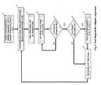
- Fig. 2 is a flow diagram describing a possible adaptive process for adjustment of the imbalance compensation.
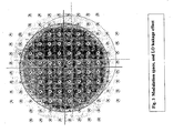
- Fig. 3 shows a 128 QAM cross constellation and the influence of a DC offset due to an LO leakage component.
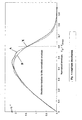
- Fig. 4 shows the amplitude distribution change due to an LO leakage component.
- the present invention provides a solution that includes a simple digital implementation that does not have specific requirements for high-speed AD/DA (analog-to-digital/digital-to-analog) devices or critical timing, which otherwise would represent a problem in conventional techniques utilising correlation methods.
- AD/DA analog-to-digital/digital-to-analog
- the present invention provides a method, an arrangement and a product that exhibit the features recited in the accompanying patent claims.
- FIG. 3 A 128 cross constellation ( as constituted by a twelve by twelve matrix with four elements omitted at each of the outer comers) is shown, with the grayscale shaded areas conceptually indicating the probability density for the vector to be in a given position in the modulation space at a selected point in time, denoted by "t".
- the reference system is drawn in solid lines.
- the inventors have performed simulations to show the relative frequency of the different amplitudes occuring in the modulation space, by computing integration of the density for a large number of amplitudes for to different conditions of impairments, with results as shown in Fig. 4.
- the curve diagrams generally indicate that the probability density of having a particular amplitude occuring increases almost linearly over a significant amplitude range. Since the amplitude frequency (i.e.
- the rate at which a particular amplitude occurs may be interpreted as the result of performing an integration of the probability density for a particular phase and amplitude in the modulation space, around the circle defined by the amplitude, the shades of gray that are shown in figure 3 has support to be understood as a "colour picture" wherein a particular color is indicative of a corresponding probability density.
- colour picture wherein a particular color is indicative of a corresponding probability density.
- FIG 3 an example of a circle for integration at one particular amplitude in a case with no significant LO leakage is indicated by a circle drawn in solid, while a circle for integration at a corresponding amplitude in a case with some LO leakage is indicated by a circle drawn in a broken line.
- the distribution indicated in fig 3 could be further distorted into e.g. an elliptic shape, which again by comptuing the integration around circles for various amplitudes would lead to a differently shaped amplitude distribution curve than those already shown in fig. 4.
- a quadrature error is understood to mean that when mapping the component functions onto a plane, the coordinate axes are not orthogonal. If we assume that the I- component is aligned with an orthogonal coordinate system x,y, we can say that the Q- component has an angle ⁇ with the I-axis. The effect of ⁇ not being 90° is that the circular indications of probability are reshaped to become ellipses. As every area element is reduced by cos ⁇ by this transformation, the probability density in every mapped point is inversely scaled.
- V OPT the point of intersection
- E Thresh is the signal envelope detector output value when the normalised signal amplitude is V OPT . It should be noted that the mathematical relation between E Thresh and V OPT is dependent on the characteristics of the envelope detector.
- E c will be a good measure for the wanted "tail area" if N is made sufficiently large.
- the estimate for E c will in a practical implementation be extracted from the envelope of the RF signal. Feeding the envelope to a comparator and setting the reference to E Thresh will give us the desired c(t).
- This two state signal i.e. c(t)
- the solution to the imbalance problem is then reduced to the task of minimising E c with respect to (i), (ii) and (iii). This can be done by varying the three imbalance parameters and measure the corresponding change in E c .
- a possible process for this is shown in Fig. 2.
- An alternative process may be employed with the same detector solution, however, giving a different response pattern. The essential part, though, is to use the detector output information in a valid manner.
- Fig. 1 shows a simplified block diagram of a quadrature modulator with an exemplary embodyment of the invention.
- I- and Q-data are entering the block with reference number 20.
- This block performs a traditional quadrature adjustment by adding controlled cross talk of I onto Q and vice versa.
- I- and Q-channel gain are scaled by a factor with opposite sign for I-and Q-channel.
- the magnitude of both quadrature and gain adjustment are output from 10.
- I- and Q-data are further passed on to D/A converters 60 and the ordinary unwanted images from the conversion process are filtered in 80 before the signal is converted to RF or IF in 100 .
- the conversion stage is done in quadrature, meaning that the local oscillator signal from 90 is phase shifted in 110 so that the LO feeding the Q-channel mixer is 90° out of phase with respect to the LO feeding the I-channel mixer.
- a diode-based detector 130 will give us a squared estimate of the envelope, but as long as the response is monotonic this satisfies our needs.
- the output from 130 is split and one part led to a comparator 120 .
- the envelope is compared to a configurable threshold from 55. This threshold can be thought of as a trigger on the envelope: If the instantaneous envelope value is above the trigger, a logical 1 is the output from 120 , otherwise a logical 0 is the output.
- This comparator value is sampled and accumulated in the digital domain in 30 according to Equation 4. After each NT second the adaptive process for imbalance correction 10 receives a new estimate for E C and outputs an adjustment.
- Block 10 has four outputs for adjustment of imbalance according to (i),(ii) and (iii), where the LO leakage occupies two of the outputs.
- DC_I and DC_Q are converted to analogue DC voltages at the output of 50 and applied as DC correction voltages at the input stage of 100 .
- the other branch from the envelope detector 130 is low pass filtered in 140 and so that the mean value of the RF signal is extracted and sampled in 70. This information is required in order to ensure that the E Thresh parameter approximately follows gain variations of the IF/RF signal.
- the E Thresh is continuously adjusted in the Envelope Threshold Compensation block 40. Denote the output from 70 as E MEAN .
- the inventors have found that good correspondence with Vopt is achieved by setting the value of A to about 4 dB. The optimum setting of A and C is reached when a gain difference at IF/RF has minimum impact on the estimate for E c .
- a new parameter value is computed and applied to the hardware. Then the accumulate time window counter ATW is started in 13 to keep track of the configurable integration time. The next step 14 samples and accumulates the comparator output according to Equation 4.
- the Env_Count variable is equivalent to E c except for the lack of normalisation. This accumulation is performed until the test in block 15 indicates that the ATW counter has reached the integration time NT. A comparison of the current Env_count against the stored Env_count from last iteration is performed in 16 . If the new estimate is greater than the old, we are obviously moving the parameter in the wrong direction and hence the direction property for this parameter is inverted in 17 so that the next time the parameter is tuned it will be in an opposite direction of the current one.
- the adjustment of the parameter is temporarily stopped and the parameter selector k, increases by one, meaning that a different parameter will be tuned next time. k wraps around when it reaches 3. If the output from 15 is NO, the adjustment was successful and no change of direction or parameter is performed. The process ends up in 18 where the obtained estimate gets status as the old estimate. This means that the process has a memory of one envelope count estimate. The process then goes into an infinite loop back to 12 . In this way we cycle through the four parameters and perform an independent adjustment of each.
- the described system can be improved by introducing a enable/disable signal for the Env_Count accumulation variable.
- the idea is to enable counting only when the modulation trajectory corresponds to certain transmitted symbol sequences, e.g. selected comer points when detecting quadrature error.
Landscapes
- Engineering & Computer Science (AREA)
- Computer Networks & Wireless Communication (AREA)
- Signal Processing (AREA)
- Digital Transmission Methods That Use Modulated Carrier Waves (AREA)
- Transmitters (AREA)
- Optical Communication System (AREA)
- Ultra Sonic Daignosis Equipment (AREA)
- Variable-Direction Aerials And Aerial Arrays (AREA)
Applications Claiming Priority (2)
| Application Number | Priority Date | Filing Date | Title |
|---|---|---|---|
| NO20033695 | 2003-08-20 | ||
| NO20033695A NO321303B1 (no) | 2003-08-20 | 2003-08-20 | Adaptiv ubalansekorrigering i en kvadraturmodulator |
Publications (2)
| Publication Number | Publication Date |
|---|---|
| EP1511264A1 true EP1511264A1 (de) | 2005-03-02 |
| EP1511264B1 EP1511264B1 (de) | 2010-03-31 |
Family
ID=28036457
Family Applications (1)
| Application Number | Title | Priority Date | Filing Date |
|---|---|---|---|
| EP04019674A Expired - Lifetime EP1511264B1 (de) | 2003-08-20 | 2004-08-19 | Adaptive Ungleichgewichtskorrektur basierend auf Amplitudenverteilung |
Country Status (4)
| Country | Link |
|---|---|
| EP (1) | EP1511264B1 (de) |
| AT (1) | ATE463114T1 (de) |
| DE (1) | DE602004026255D1 (de) |
| NO (1) | NO321303B1 (de) |
Cited By (2)
| Publication number | Priority date | Publication date | Assignee | Title |
|---|---|---|---|---|
| DE102005013881A1 (de) * | 2005-03-24 | 2006-09-28 | Infineon Technologies Ag | Verfahren zur Signalverarbeitung und Sendeeinrichtung mit digitaler Vorverzerrung, insbesondere für den Mobilfunk |
| EP1895736A3 (de) * | 2006-08-30 | 2008-05-21 | Nera networks | Verfahren und Vorrichtung zur Erkennung und Schätzung von Quadraturfehlern |
Citations (3)
| Publication number | Priority date | Publication date | Assignee | Title |
|---|---|---|---|---|
| EP0324581A2 (de) * | 1988-01-13 | 1989-07-19 | Hewlett-Packard Company | Abgleichung von Vektordemodulatoren unter Verwendung einer statistischen Analyse |
| EP0617432A2 (de) | 1993-03-25 | 1994-09-28 | Ngk Insulators, Ltd. | Elektrischer Verbundisolator und Verfahren zu seiner Herstellung |
| EP0617532A1 (de) * | 1993-03-24 | 1994-09-28 | Nokia Mobile Phones Ltd. | Kalibrierungsverfahren für Vektormodulatoren |
-
2003
- 2003-08-20 NO NO20033695A patent/NO321303B1/no not_active IP Right Cessation
-
2004
- 2004-08-19 AT AT04019674T patent/ATE463114T1/de not_active IP Right Cessation
- 2004-08-19 EP EP04019674A patent/EP1511264B1/de not_active Expired - Lifetime
- 2004-08-19 DE DE602004026255T patent/DE602004026255D1/de not_active Expired - Lifetime
Patent Citations (3)
| Publication number | Priority date | Publication date | Assignee | Title |
|---|---|---|---|---|
| EP0324581A2 (de) * | 1988-01-13 | 1989-07-19 | Hewlett-Packard Company | Abgleichung von Vektordemodulatoren unter Verwendung einer statistischen Analyse |
| EP0617532A1 (de) * | 1993-03-24 | 1994-09-28 | Nokia Mobile Phones Ltd. | Kalibrierungsverfahren für Vektormodulatoren |
| EP0617432A2 (de) | 1993-03-25 | 1994-09-28 | Ngk Insulators, Ltd. | Elektrischer Verbundisolator und Verfahren zu seiner Herstellung |
Cited By (2)
| Publication number | Priority date | Publication date | Assignee | Title |
|---|---|---|---|---|
| DE102005013881A1 (de) * | 2005-03-24 | 2006-09-28 | Infineon Technologies Ag | Verfahren zur Signalverarbeitung und Sendeeinrichtung mit digitaler Vorverzerrung, insbesondere für den Mobilfunk |
| EP1895736A3 (de) * | 2006-08-30 | 2008-05-21 | Nera networks | Verfahren und Vorrichtung zur Erkennung und Schätzung von Quadraturfehlern |
Also Published As
| Publication number | Publication date |
|---|---|
| ATE463114T1 (de) | 2010-04-15 |
| NO321303B1 (no) | 2006-04-24 |
| EP1511264B1 (de) | 2010-03-31 |
| NO20033695L (no) | 2005-02-21 |
| NO20033695D0 (no) | 2003-08-20 |
| DE602004026255D1 (de) | 2010-05-12 |
Similar Documents
| Publication | Publication Date | Title |
|---|---|---|
| US5113414A (en) | Predistortion arrangement for a digital transmission system | |
| US6931343B2 (en) | On-signal quadrature modulator calibration | |
| US8265489B2 (en) | Optical field transmitter and optical field transmission system | |
| US6798844B2 (en) | Correction of phase and amplitude imbalance of I/Q modulator | |
| EP0617532B1 (de) | Kalibrierungsverfahren für Vektormodulatoren | |
| EP1378100B1 (de) | Gesteuerte modulationsverzerrung | |
| CN1390393A (zh) | 直接变频接收机的干扰补偿设备和方法 | |
| EP0684718A1 (de) | Digitale Demodulationseinrichtung | |
| CA1192615A (en) | Carrier recovery circuit | |
| US7248639B2 (en) | Method for reducing the out-of-band emission in AM transmitters for digital transmission | |
| CA2148200C (en) | Method and apparatus for recovering a qam carrier | |
| US4882547A (en) | Linearizer control system | |
| US12034571B2 (en) | Modulation and demodulation for enhanced noise margins in 5G and 6G | |
| US20030157905A1 (en) | Transmitter and associated method for reducing the adjacent channel power during wireless communications | |
| US8027408B2 (en) | ASK modulator | |
| EP1511264B1 (de) | Adaptive Ungleichgewichtskorrektur basierend auf Amplitudenverteilung | |
| EP3297237A1 (de) | Verfahren und system zur erzeugung eines angepassten sendesignals | |
| JP4474252B2 (ja) | 直角変調法の複素位相空間において記号を決定するための方法および回路配置 | |
| US6744827B1 (en) | Demodulator arrangement, method to demodulate, and telecommunication system comprising such a demodulator arrangement | |
| US20250260603A1 (en) | Waveform Modulation for Fault Mitigation in 5G/6G | |
| US6614851B1 (en) | Efficient algorithm for blind detection of signal constellation | |
| US8514977B2 (en) | Transmission apparatus, reception apparatus, transmission method, and reception method of wireless communication system | |
| EP2547059B1 (de) | Sender mit Kalibrierung eines In-Phasen/Quadratur (I/Q)-Modulators, und dazugehörige Verfahren | |
| JPH0568060A (ja) | 歪補償直交変調器 | |
| US20040066857A1 (en) | Reducing I/Q imbalance through image rejection |
Legal Events
| Date | Code | Title | Description |
|---|---|---|---|
| PUAI | Public reference made under article 153(3) epc to a published international application that has entered the european phase |
Free format text: ORIGINAL CODE: 0009012 |
|
| 17P | Request for examination filed |
Effective date: 20040819 |
|
| AK | Designated contracting states |
Kind code of ref document: A1 Designated state(s): AT BE BG CH CY CZ DE DK EE ES FI FR GB GR HU IE IT LI LU MC NL PL PT RO SE SI SK TR |
|
| AX | Request for extension of the european patent |
Extension state: AL HR LT LV MK |
|
| AKX | Designation fees paid |
Designated state(s): AT BE BG CH CY CZ DE DK EE ES FI FR GB GR HU IE IT LI LU MC NL PL PT RO SE SI SK TR |
|
| 17Q | First examination report despatched |
Effective date: 20070510 |
|
| GRAP | Despatch of communication of intention to grant a patent |
Free format text: ORIGINAL CODE: EPIDOSNIGR1 |
|
| RAP1 | Party data changed (applicant data changed or rights of an application transferred) |
Owner name: NERA NETWORKS AS |
|
| GRAS | Grant fee paid |
Free format text: ORIGINAL CODE: EPIDOSNIGR3 |
|
| GRAA | (expected) grant |
Free format text: ORIGINAL CODE: 0009210 |
|
| AK | Designated contracting states |
Kind code of ref document: B1 Designated state(s): AT BE BG CH CY CZ DE DK EE ES FI FR GB GR HU IE IT LI LU MC NL PL PT RO SE SI SK TR |
|
| REG | Reference to a national code |
Ref country code: GB Ref legal event code: FG4D Ref country code: CH Ref legal event code: EP |
|
| REG | Reference to a national code |
Ref country code: IE Ref legal event code: FG4D |
|
| REF | Corresponds to: |
Ref document number: 602004026255 Country of ref document: DE Date of ref document: 20100512 Kind code of ref document: P |
|
| REG | Reference to a national code |
Ref country code: NL Ref legal event code: VDEP Effective date: 20100331 |
|
| PG25 | Lapsed in a contracting state [announced via postgrant information from national office to epo] |
Ref country code: SI Free format text: LAPSE BECAUSE OF FAILURE TO SUBMIT A TRANSLATION OF THE DESCRIPTION OR TO PAY THE FEE WITHIN THE PRESCRIBED TIME-LIMIT Effective date: 20100331 Ref country code: AT Free format text: LAPSE BECAUSE OF FAILURE TO SUBMIT A TRANSLATION OF THE DESCRIPTION OR TO PAY THE FEE WITHIN THE PRESCRIBED TIME-LIMIT Effective date: 20100331 Ref country code: FI Free format text: LAPSE BECAUSE OF FAILURE TO SUBMIT A TRANSLATION OF THE DESCRIPTION OR TO PAY THE FEE WITHIN THE PRESCRIBED TIME-LIMIT Effective date: 20100331 Ref country code: PL Free format text: LAPSE BECAUSE OF FAILURE TO SUBMIT A TRANSLATION OF THE DESCRIPTION OR TO PAY THE FEE WITHIN THE PRESCRIBED TIME-LIMIT Effective date: 20100331 |
|
| PG25 | Lapsed in a contracting state [announced via postgrant information from national office to epo] |
Ref country code: RO Free format text: LAPSE BECAUSE OF FAILURE TO SUBMIT A TRANSLATION OF THE DESCRIPTION OR TO PAY THE FEE WITHIN THE PRESCRIBED TIME-LIMIT Effective date: 20100331 Ref country code: NL Free format text: LAPSE BECAUSE OF FAILURE TO SUBMIT A TRANSLATION OF THE DESCRIPTION OR TO PAY THE FEE WITHIN THE PRESCRIBED TIME-LIMIT Effective date: 20100331 Ref country code: ES Free format text: LAPSE BECAUSE OF FAILURE TO SUBMIT A TRANSLATION OF THE DESCRIPTION OR TO PAY THE FEE WITHIN THE PRESCRIBED TIME-LIMIT Effective date: 20100712 Ref country code: EE Free format text: LAPSE BECAUSE OF FAILURE TO SUBMIT A TRANSLATION OF THE DESCRIPTION OR TO PAY THE FEE WITHIN THE PRESCRIBED TIME-LIMIT Effective date: 20100331 Ref country code: BE Free format text: LAPSE BECAUSE OF FAILURE TO SUBMIT A TRANSLATION OF THE DESCRIPTION OR TO PAY THE FEE WITHIN THE PRESCRIBED TIME-LIMIT Effective date: 20100331 Ref country code: CY Free format text: LAPSE BECAUSE OF FAILURE TO SUBMIT A TRANSLATION OF THE DESCRIPTION OR TO PAY THE FEE WITHIN THE PRESCRIBED TIME-LIMIT Effective date: 20100331 Ref country code: SE Free format text: LAPSE BECAUSE OF FAILURE TO SUBMIT A TRANSLATION OF THE DESCRIPTION OR TO PAY THE FEE WITHIN THE PRESCRIBED TIME-LIMIT Effective date: 20100331 |
|
| PG25 | Lapsed in a contracting state [announced via postgrant information from national office to epo] |
Ref country code: CZ Free format text: LAPSE BECAUSE OF FAILURE TO SUBMIT A TRANSLATION OF THE DESCRIPTION OR TO PAY THE FEE WITHIN THE PRESCRIBED TIME-LIMIT Effective date: 20100331 Ref country code: SK Free format text: LAPSE BECAUSE OF FAILURE TO SUBMIT A TRANSLATION OF THE DESCRIPTION OR TO PAY THE FEE WITHIN THE PRESCRIBED TIME-LIMIT Effective date: 20100331 |
|
| PG25 | Lapsed in a contracting state [announced via postgrant information from national office to epo] |
Ref country code: DK Free format text: LAPSE BECAUSE OF FAILURE TO SUBMIT A TRANSLATION OF THE DESCRIPTION OR TO PAY THE FEE WITHIN THE PRESCRIBED TIME-LIMIT Effective date: 20100331 Ref country code: PT Free format text: LAPSE BECAUSE OF FAILURE TO SUBMIT A TRANSLATION OF THE DESCRIPTION OR TO PAY THE FEE WITHIN THE PRESCRIBED TIME-LIMIT Effective date: 20100802 |
|
| PLBE | No opposition filed within time limit |
Free format text: ORIGINAL CODE: 0009261 |
|
| STAA | Information on the status of an ep patent application or granted ep patent |
Free format text: STATUS: NO OPPOSITION FILED WITHIN TIME LIMIT |
|
| 26N | No opposition filed |
Effective date: 20110104 |
|
| PG25 | Lapsed in a contracting state [announced via postgrant information from national office to epo] |
Ref country code: MC Free format text: LAPSE BECAUSE OF NON-PAYMENT OF DUE FEES Effective date: 20100831 Ref country code: IT Free format text: LAPSE BECAUSE OF FAILURE TO SUBMIT A TRANSLATION OF THE DESCRIPTION OR TO PAY THE FEE WITHIN THE PRESCRIBED TIME-LIMIT Effective date: 20100331 |
|
| REG | Reference to a national code |
Ref country code: CH Ref legal event code: PL |
|
| PG25 | Lapsed in a contracting state [announced via postgrant information from national office to epo] |
Ref country code: CH Free format text: LAPSE BECAUSE OF NON-PAYMENT OF DUE FEES Effective date: 20100831 Ref country code: LI Free format text: LAPSE BECAUSE OF NON-PAYMENT OF DUE FEES Effective date: 20100831 |
|
| REG | Reference to a national code |
Ref country code: FR Ref legal event code: ST Effective date: 20110502 |
|
| REG | Reference to a national code |
Ref country code: DE Ref legal event code: R119 Ref document number: 602004026255 Country of ref document: DE Effective date: 20110301 |
|
| PG25 | Lapsed in a contracting state [announced via postgrant information from national office to epo] |
Ref country code: IE Free format text: LAPSE BECAUSE OF NON-PAYMENT OF DUE FEES Effective date: 20100819 Ref country code: DE Free format text: LAPSE BECAUSE OF NON-PAYMENT OF DUE FEES Effective date: 20110301 Ref country code: FR Free format text: LAPSE BECAUSE OF NON-PAYMENT OF DUE FEES Effective date: 20100831 |
|
| PG25 | Lapsed in a contracting state [announced via postgrant information from national office to epo] |
Ref country code: HU Free format text: LAPSE BECAUSE OF FAILURE TO SUBMIT A TRANSLATION OF THE DESCRIPTION OR TO PAY THE FEE WITHIN THE PRESCRIBED TIME-LIMIT Effective date: 20101001 Ref country code: BG Free format text: LAPSE BECAUSE OF FAILURE TO SUBMIT A TRANSLATION OF THE DESCRIPTION OR TO PAY THE FEE WITHIN THE PRESCRIBED TIME-LIMIT Effective date: 20100331 Ref country code: LU Free format text: LAPSE BECAUSE OF NON-PAYMENT OF DUE FEES Effective date: 20100819 |
|
| PG25 | Lapsed in a contracting state [announced via postgrant information from national office to epo] |
Ref country code: TR Free format text: LAPSE BECAUSE OF FAILURE TO SUBMIT A TRANSLATION OF THE DESCRIPTION OR TO PAY THE FEE WITHIN THE PRESCRIBED TIME-LIMIT Effective date: 20100331 |
|
| PGFP | Annual fee paid to national office [announced via postgrant information from national office to epo] |
Ref country code: GB Payment date: 20120815 Year of fee payment: 9 |
|
| PG25 | Lapsed in a contracting state [announced via postgrant information from national office to epo] |
Ref country code: BG Free format text: LAPSE BECAUSE OF FAILURE TO SUBMIT A TRANSLATION OF THE DESCRIPTION OR TO PAY THE FEE WITHIN THE PRESCRIBED TIME-LIMIT Effective date: 20100630 |
|
| GBPC | Gb: european patent ceased through non-payment of renewal fee |
Effective date: 20130819 |
|
| PG25 | Lapsed in a contracting state [announced via postgrant information from national office to epo] |
Ref country code: GB Free format text: LAPSE BECAUSE OF NON-PAYMENT OF DUE FEES Effective date: 20130819 |
|
| PG25 | Lapsed in a contracting state [announced via postgrant information from national office to epo] |
Ref country code: GR Free format text: LAPSE BECAUSE OF FAILURE TO SUBMIT A TRANSLATION OF THE DESCRIPTION OR TO PAY THE FEE WITHIN THE PRESCRIBED TIME-LIMIT Effective date: 20100331 |