EP1511028A1 - Optical recording medium, and optical storage device - Google Patents
Optical recording medium, and optical storage device Download PDFInfo
- Publication number
- EP1511028A1 EP1511028A1 EP02730850A EP02730850A EP1511028A1 EP 1511028 A1 EP1511028 A1 EP 1511028A1 EP 02730850 A EP02730850 A EP 02730850A EP 02730850 A EP02730850 A EP 02730850A EP 1511028 A1 EP1511028 A1 EP 1511028A1
- Authority
- EP
- European Patent Office
- Prior art keywords
- layer
- recording medium
- optical recording
- land
- magneto
- Prior art date
- Legal status (The legal status is an assumption and is not a legal conclusion. Google has not performed a legal analysis and makes no representation as to the accuracy of the status listed.)
- Withdrawn
Links
Images






Classifications
-
- G—PHYSICS
- G11—INFORMATION STORAGE
- G11B—INFORMATION STORAGE BASED ON RELATIVE MOVEMENT BETWEEN RECORD CARRIER AND TRANSDUCER
- G11B7/00—Recording or reproducing by optical means, e.g. recording using a thermal beam of optical radiation by modifying optical properties or the physical structure, reproducing using an optical beam at lower power by sensing optical properties; Record carriers therefor
- G11B7/24—Record carriers characterised by shape, structure or physical properties, or by the selection of the material
- G11B7/2407—Tracks or pits; Shape, structure or physical properties thereof
- G11B7/24073—Tracks
- G11B7/24076—Cross sectional shape in the radial direction of a disc, e.g. asymmetrical cross sectional shape
-
- G—PHYSICS
- G11—INFORMATION STORAGE
- G11B—INFORMATION STORAGE BASED ON RELATIVE MOVEMENT BETWEEN RECORD CARRIER AND TRANSDUCER
- G11B11/00—Recording on or reproducing from the same record carrier wherein for these two operations the methods are covered by different main groups of groups G11B3/00 - G11B7/00 or by different subgroups of group G11B9/00; Record carriers therefor
- G11B11/10—Recording on or reproducing from the same record carrier wherein for these two operations the methods are covered by different main groups of groups G11B3/00 - G11B7/00 or by different subgroups of group G11B9/00; Record carriers therefor using recording by magnetic means or other means for magnetisation or demagnetisation of a record carrier, e.g. light induced spin magnetisation; Demagnetisation by thermal or stress means in the presence or not of an orienting magnetic field
- G11B11/105—Recording on or reproducing from the same record carrier wherein for these two operations the methods are covered by different main groups of groups G11B3/00 - G11B7/00 or by different subgroups of group G11B9/00; Record carriers therefor using recording by magnetic means or other means for magnetisation or demagnetisation of a record carrier, e.g. light induced spin magnetisation; Demagnetisation by thermal or stress means in the presence or not of an orienting magnetic field using a beam of light or a magnetic field for recording by change of magnetisation and a beam of light for reproducing, i.e. magneto-optical, e.g. light-induced thermomagnetic recording, spin magnetisation recording, Kerr or Faraday effect reproducing
-
- G—PHYSICS
- G11—INFORMATION STORAGE
- G11B—INFORMATION STORAGE BASED ON RELATIVE MOVEMENT BETWEEN RECORD CARRIER AND TRANSDUCER
- G11B11/00—Recording on or reproducing from the same record carrier wherein for these two operations the methods are covered by different main groups of groups G11B3/00 - G11B7/00 or by different subgroups of group G11B9/00; Record carriers therefor
- G11B11/10—Recording on or reproducing from the same record carrier wherein for these two operations the methods are covered by different main groups of groups G11B3/00 - G11B7/00 or by different subgroups of group G11B9/00; Record carriers therefor using recording by magnetic means or other means for magnetisation or demagnetisation of a record carrier, e.g. light induced spin magnetisation; Demagnetisation by thermal or stress means in the presence or not of an orienting magnetic field
- G11B11/105—Recording on or reproducing from the same record carrier wherein for these two operations the methods are covered by different main groups of groups G11B3/00 - G11B7/00 or by different subgroups of group G11B9/00; Record carriers therefor using recording by magnetic means or other means for magnetisation or demagnetisation of a record carrier, e.g. light induced spin magnetisation; Demagnetisation by thermal or stress means in the presence or not of an orienting magnetic field using a beam of light or a magnetic field for recording by change of magnetisation and a beam of light for reproducing, i.e. magneto-optical, e.g. light-induced thermomagnetic recording, spin magnetisation recording, Kerr or Faraday effect reproducing
- G11B11/1055—Disposition or mounting of transducers relative to record carriers
- G11B11/10576—Disposition or mounting of transducers relative to record carriers with provision for moving the transducers for maintaining alignment or spacing relative to the carrier
- G11B11/10578—Servo format, e.g. prepits, guide tracks, pilot signals
-
- G—PHYSICS
- G11—INFORMATION STORAGE
- G11B—INFORMATION STORAGE BASED ON RELATIVE MOVEMENT BETWEEN RECORD CARRIER AND TRANSDUCER
- G11B11/00—Recording on or reproducing from the same record carrier wherein for these two operations the methods are covered by different main groups of groups G11B3/00 - G11B7/00 or by different subgroups of group G11B9/00; Record carriers therefor
- G11B11/10—Recording on or reproducing from the same record carrier wherein for these two operations the methods are covered by different main groups of groups G11B3/00 - G11B7/00 or by different subgroups of group G11B9/00; Record carriers therefor using recording by magnetic means or other means for magnetisation or demagnetisation of a record carrier, e.g. light induced spin magnetisation; Demagnetisation by thermal or stress means in the presence or not of an orienting magnetic field
- G11B11/105—Recording on or reproducing from the same record carrier wherein for these two operations the methods are covered by different main groups of groups G11B3/00 - G11B7/00 or by different subgroups of group G11B9/00; Record carriers therefor using recording by magnetic means or other means for magnetisation or demagnetisation of a record carrier, e.g. light induced spin magnetisation; Demagnetisation by thermal or stress means in the presence or not of an orienting magnetic field using a beam of light or a magnetic field for recording by change of magnetisation and a beam of light for reproducing, i.e. magneto-optical, e.g. light-induced thermomagnetic recording, spin magnetisation recording, Kerr or Faraday effect reproducing
- G11B11/10582—Record carriers characterised by the selection of the material or by the structure or form
- G11B11/10584—Record carriers characterised by the selection of the material or by the structure or form characterised by the form, e.g. comprising mechanical protection elements
-
- G—PHYSICS
- G11—INFORMATION STORAGE
- G11B—INFORMATION STORAGE BASED ON RELATIVE MOVEMENT BETWEEN RECORD CARRIER AND TRANSDUCER
- G11B7/00—Recording or reproducing by optical means, e.g. recording using a thermal beam of optical radiation by modifying optical properties or the physical structure, reproducing using an optical beam at lower power by sensing optical properties; Record carriers therefor
- G11B7/007—Arrangement of the information on the record carrier, e.g. form of tracks, actual track shape, e.g. wobbled, or cross-section, e.g. v-shaped; Sequential information structures, e.g. sectoring or header formats within a track
- G11B7/00718—Groove and land recording, i.e. user data recorded both in the grooves and on the lands
-
- G—PHYSICS
- G11—INFORMATION STORAGE
- G11B—INFORMATION STORAGE BASED ON RELATIVE MOVEMENT BETWEEN RECORD CARRIER AND TRANSDUCER
- G11B7/00—Recording or reproducing by optical means, e.g. recording using a thermal beam of optical radiation by modifying optical properties or the physical structure, reproducing using an optical beam at lower power by sensing optical properties; Record carriers therefor
- G11B7/24—Record carriers characterised by shape, structure or physical properties, or by the selection of the material
- G11B7/2407—Tracks or pits; Shape, structure or physical properties thereof
- G11B7/24073—Tracks
- G11B7/24079—Width or depth
-
- G—PHYSICS
- G11—INFORMATION STORAGE
- G11B—INFORMATION STORAGE BASED ON RELATIVE MOVEMENT BETWEEN RECORD CARRIER AND TRANSDUCER
- G11B11/00—Recording on or reproducing from the same record carrier wherein for these two operations the methods are covered by different main groups of groups G11B3/00 - G11B7/00 or by different subgroups of group G11B9/00; Record carriers therefor
- G11B11/10—Recording on or reproducing from the same record carrier wherein for these two operations the methods are covered by different main groups of groups G11B3/00 - G11B7/00 or by different subgroups of group G11B9/00; Record carriers therefor using recording by magnetic means or other means for magnetisation or demagnetisation of a record carrier, e.g. light induced spin magnetisation; Demagnetisation by thermal or stress means in the presence or not of an orienting magnetic field
- G11B11/105—Recording on or reproducing from the same record carrier wherein for these two operations the methods are covered by different main groups of groups G11B3/00 - G11B7/00 or by different subgroups of group G11B9/00; Record carriers therefor using recording by magnetic means or other means for magnetisation or demagnetisation of a record carrier, e.g. light induced spin magnetisation; Demagnetisation by thermal or stress means in the presence or not of an orienting magnetic field using a beam of light or a magnetic field for recording by change of magnetisation and a beam of light for reproducing, i.e. magneto-optical, e.g. light-induced thermomagnetic recording, spin magnetisation recording, Kerr or Faraday effect reproducing
- G11B11/10532—Heads
- G11B11/10541—Heads for reproducing
- G11B11/10543—Heads for reproducing using optical beam of radiation
-
- G—PHYSICS
- G11—INFORMATION STORAGE
- G11B—INFORMATION STORAGE BASED ON RELATIVE MOVEMENT BETWEEN RECORD CARRIER AND TRANSDUCER
- G11B11/00—Recording on or reproducing from the same record carrier wherein for these two operations the methods are covered by different main groups of groups G11B3/00 - G11B7/00 or by different subgroups of group G11B9/00; Record carriers therefor
- G11B11/10—Recording on or reproducing from the same record carrier wherein for these two operations the methods are covered by different main groups of groups G11B3/00 - G11B7/00 or by different subgroups of group G11B9/00; Record carriers therefor using recording by magnetic means or other means for magnetisation or demagnetisation of a record carrier, e.g. light induced spin magnetisation; Demagnetisation by thermal or stress means in the presence or not of an orienting magnetic field
- G11B11/105—Recording on or reproducing from the same record carrier wherein for these two operations the methods are covered by different main groups of groups G11B3/00 - G11B7/00 or by different subgroups of group G11B9/00; Record carriers therefor using recording by magnetic means or other means for magnetisation or demagnetisation of a record carrier, e.g. light induced spin magnetisation; Demagnetisation by thermal or stress means in the presence or not of an orienting magnetic field using a beam of light or a magnetic field for recording by change of magnetisation and a beam of light for reproducing, i.e. magneto-optical, e.g. light-induced thermomagnetic recording, spin magnetisation recording, Kerr or Faraday effect reproducing
- G11B11/10582—Record carriers characterised by the selection of the material or by the structure or form
- G11B11/10586—Record carriers characterised by the selection of the material or by the structure or form characterised by the selection of the material
Definitions
- the present invention relates generally to an optical recording medium, and more particularly to a land/groove recording type magneto-optical recording medium.
- a method of shortening the wavelength of a laser to be used in recording or reproducing data is investigated as one method for increasing a recording density on an optical disk.
- the wavelength of a laser used in a 3.5-inch magneto-optical disk drive at present is 650 nm.
- the diameter of a beam spot on a recording surface of the disk can be reduced from about 1.0 ⁇ m to 0.65 ⁇ m, thereby allowing high-density recording.
- a magneto-optical disk is known as a high-density recording medium, and an increase in its recording density is demanded with an increase in quantity of information.
- Increasing the recording density of the medium can be realized by shortening the space between adjacent recording marks.
- the reproduction of each recording mark is limited by the size of a light beam (beam spot) on the medium.
- the density of the recording marks is set so that only one recording mark is present inside the beam spot, an output waveform corresponding to "1" or "0" can be observed as a reproduced signal according to whether or not the recording mark is present inside the beam spot.
- the reproduced output does not change irrespective of movement of the beam spot on the medium, so that the output waveform becomes linear and the presence or absence of recording marks cannot be distinguished.
- the reproduction of such small recording marks having a period shorter than the size of the beam spot may be effected by reducing the size of the beam spot.
- the size of the beam spot is limited by the wavelength ⁇ of light output from a light source and the numerical aperture NA of an objective lens, so that the spot size cannot be sufficiently reduced.
- MSR magnetically induced super-resolution
- a CAD (center aperture detection) type MSR medium such that a nonmagnetic layer is interposed between a reproducing layer and a recording layer, and a recorded mark in the recording layer is transferred to the reproducing layer by magnetostatic coupling to thereby reproduce information.
- a longitudinally magnetized film having an axis of easy magnetization in a longitudinal direction at room temperature is used as the reproducing layer, and the recorded mark in the recording layer at only a portion heated to a high temperature by the irradiation with a laser beam is transferred to the reproducing layer to thereby mask the other portion except the above heated portion for reproduction by means of the reproducing layer, thus allowing super-resolution reproduction.
- longitudinal magnetization in the reproducing layer at the other portion except the aperture portion is not detected, and it is resistant against crosstalk from the adjacent track, thereby allowing a reduction in track pitch.
- the development for reducing the beam diameter has become active by using a short-wavelength laser or a high-NA lens as means for realizing the high recording density on an optical disk.
- the beam spot diameter is about 1.0 ⁇ m (1/e 2 ).
- the beam spot diameter can be reduced to about 0.65 ⁇ m. Reducing the beam spot diameter can improve a resolution, so that a small mark can be recorded to thereby increase the recording density.
- an optical recording medium having recording tracks consisting of a plurality of lands and a plurality of grooves, wherein the diameter of a laser beam to be used for recording/reproduction on a recording surface of the medium is 0.7 ⁇ m or less, the optical recording medium comprising a transparent substrate on which the lands and the grooves are alternately formed; and an optically recordable recording layer provided on the transparent substrate; the width w1 of each land at the center of the height of the boundary between each land and each groove adjacent thereto, the width w2 of a flat top surface of each land, and the depth d of each groove being set to 0.4 ⁇ w2/w1 ⁇ 0.8 and 25 nm ⁇ d ⁇ 45 nm; at least each land having an edge portion formed as a curved surface.
- each groove has an edge portion formed as a curved surface
- the recording layer comprises a magneto-optical recording layer formed of a rare earth-transition metal composite material.
- a magneto-optical recording medium having recording tracks consisting of a plurality of lands and a plurality of grooves, wherein the diameter of a laser beam to be used for recording/reproduction on a recording surface of the medium is 0.7 ⁇ m or less, the magneto-optical recording medium comprising a transparent substrate on which the lands and the grooves are alternately formed; a reproducing layer provided on the transparent substrate and formed of a rare earth-transition metal composite material having a relatively large Kerr rotation angle and a relatively small coercivity at room temperature; and a recording layer provided on the reproducing layer and formed of a rare earth-transition metal composite material having a relatively small Kerr rotation angle and a relatively large coercivity at room temperature; the width w1 of each land at the center of the height of the boundary between each land and each groove adjacent thereto, the width w2 of a flat top surface of each land, and the depth d of each groove being set to 0.4 ⁇
- a magneto-optical recording medium having recording tracks consisting of a plurality of lands and a plurality of grooves, wherein the diameter of a laser beam to be used for recording/reproduction on a recording surface of the medium is 0.7 ⁇ m or less, the magneto-optical recording medium comprising a transparent substrate on which the lands and the grooves are alternately formed; a first reproducing layer provided on the transparent substrate and having an axis of easy magnetization in a longitudinal direction at room temperature; a second reproducing layer provided on the first reproducing layer and having an axis of easy magnetization in a longitudinal direction at room temperature; a nonmagnetic block layer provided on the second reproducing layer; a recording layer provided on the nonmagnetic block layer and having an axis of easy magnetization in a perpendicular direction at room temperature in the case of a single layer; a nonmagnetic overcoat layer provided on the recording layer; and a metal layer provided on the nonm
- the first and second reproducing layers respectively have Curie temperatures Tc1 and Tc2 set to Tc2 ⁇ Tc1 and 160°C ⁇ Tc2 ⁇ 190°C.
- the first reproducing layer has a thickness tr1 of 25 to 35 nm
- the second reproducing layer has a thickness tr2 set to tr1 ⁇ 0.3 ⁇ tr2 ⁇ tr1 ⁇ 0.4.
- the nonmagnetic overcoat layer has a thickness of 5 to 15 nm
- the metal layer has a thickness of 50 to 90 nm
- the nonmagnetic block layer has a thickness of 0.5 to 2 nm.
- an optical storage device capable of at least reading information recorded on an optical recording medium having recording tracks consisting of a plurality of lands and a plurality of grooves, the optical storage device comprising an optical head for irradiating the optical recording medium with a laser beam having a diameter of 0.7 ⁇ m or less on a recording surface of the medium; and a photodetector for generating a reproduction signal from reflected light reflected on the optical recording medium;
- the optical recording medium comprising a transparent substrate on which the lands and the grooves are alternately formed and an optically recordable recording layer provided on the transparent substrate; the width w1 of each land at the center of the height of the boundary between each land and each groove adjacent thereto, the width w2 of a flat top surface of each land, and the depth d of each groove being set to 0.4 ⁇ w2/w1 ⁇ 0.8 and 25 nm ⁇ d ⁇ 45 nm; at least each land having an edge portion formed
- the optical storage medium 2 usually has the form of a disk.
- Reference numeral 4 denotes a transparent substrate formed of glass or polycarbonate, for example.
- the substrate 4 has a plurality of lands 8 and a plurality of grooves 10 alternately formed.
- the center distance (track pitch) between any adjacent ones of the lands 8 and the grooves 10 of the substrate 4 is 0.40 ⁇ m, for example, and a recording layer 6 is formed on the substrate 4.
- the level difference between the lands 8 and the grooves 10 of the substrate 4 is 35 nm, for example.
- the optical storage medium 2 applicable to the present invention is an optical storage medium having at least a land and a groove as recording tracks.
- As the recording layer 6, a magneto-optical recording layer or a phase-change type recording layer may be adopted, for example.
- each land 8 has a pair of edge portions 8a on the opposite sides, and each edge portion 8a is formed as a curved surface having a predetermined radius of curvature.
- each groove 10 has a pair of edge portions 10a on the opposite sides, and each edge portion 10a is formed as a curved surface having a predetermined radius of curvature.
- the width w1 of each land 8 at the center of the height of the boundary between each land 8 and each groove 10 adjacent thereto, the width w2 of a flat top surface of each land 8, and the depth d of each groove 10 are preferably set as follows: 0.4 ⁇ w2/w1 ⁇ 0.8 and 25 nm ⁇ d ⁇ 45 nm
- a groove and pits are preliminarily formed on a transparent substrate. Specifically, a stamper having a positive resist film is used and it is exposed to a laser beam at a portion except a portion corresponding to the groove and the pits. Then, the portion corresponding to the groove and the pits is formed into a projecting portion by development and etching. At this time, the etching is performed by ion milling, sputtering, or the like to provide a predetermined curvature at a portion corresponding to the edge portions of each land and the edge portions of each groove.
- the stamper thus prepared is mounted on a die of an injection molding machine, and a resin such as polycarbonate is supplied to the injection molding machine to thereby prepare the transparent substrate 4 of the optical storage medium which has a plurality of lands 8 and a plurality of grooves 10 alternately formed. Thereafter, a recording layer, protective layer, and reflective layer are formed on a transfer surface (a surface formed with the groove and the pits) of the transparent substrate 4 to thereby complete the optical storage medium.
- a manufacturing method for such a substrate is described in Japanese Patent Laid-open No. Hei 11-232707, for example.
- FIG. 2 shows the configuration of a magneto-optical recording medium 12A according to a first preferred embodiment of the present invention.
- a base dielectric layer 14 formed of SiN
- a reproducing layer 16 formed of GdFeCo
- a nonmagnetic layer 18 formed of SiN
- a recording layer 20 formed of TbFeCo in this order.
- an overcoat layer 22 formed of SiN and a metal layer 24 containing Al in this order.
- the magneto-optical recording medium 12A is a CAD (center aperture detection) type magnetically induced super-resolution (MSR) medium such that a recorded mark in the recording layer 20 is transferred to the reproducing layer 16 by magnetostatic coupling.
- the reproducing layer 16 has a relatively large Kerr rotation angle and a relatively small coercivity at room temperature as compared with the recording layer 20.
- the recording layer 20 has a relatively small Kerr rotation angle and a relatively large coercivity at room temperature as compared with the reproducing layer 16.
- FIG. 3 shows the configuration of a magneto-optical recording medium 12B according to a second preferred embodiment of the present invention.
- a base dielectric layer 14 formed of SiN
- a first reproducing layer 26 formed of GdFeCo
- a second reproducing layer 28 formed of GdFe
- a nonmagnetic layer 30 formed of SiN
- a recording layer 32 formed of TbFeCo in this order.
- an overcoat layer 22 formed of SiN and a metal layer 24 containing Al in this order.
- the metal layer 24 may be formed of a material containing Au, Cu, or Ag as a principal component.
- the magneto-optical recording medium 12B is also a CAD type MSR medium such that a recorded mark in the recording layer 32 is transferred to the second reproducing layer 28 and the first reproducing layer 26 by magnetostatic coupling.
- Each of the first reproducing layer 26 and the second reproducing layer 28 has an axis of easy magnetization in the longitudinal direction at room temperature.
- the recording layer 32 has an axis of easy magnetization in the perpendicular direction at room temperature in the case of a single layer.
- FIG. 4 shows the configuration of a magneto-optical recording medium 12C according to a third preferred embodiment of the present invention.
- a base dielectric layer 14 formed of SiN
- a first reproducing layer 26 formed of GdFeCo
- a second reproducing layer 28 formed of GdFe
- a nonmagnetic layer 30 formed of SiN
- a recording layer 32 formed of TbFeCo in this order.
- a recording assist layer 34 formed of GdFeCo
- an overcoat layer 22 formed of SiN and a metal layer 24 containing Al in this order.
- the magneto-optical recording medium 12C is also a CAD type MSR medium such that a recorded mark in the recording layer 32 is transferred to the second reproducing layer 28 and the first reproducing layer 26 by magnetostatic coupling.
- Each of the first reproducing layer 26 and the second reproducing layer 28 has an axis of easy magnetization in the longitudinal direction at room temperature.
- the recording layer 32 has an axis of easy magnetization in the perpendicular direction at room temperature in the case of a single layer.
- FIG. 5 shows the configuration of a magneto-optical recording medium 12D according to a fourth preferred embodiment of the present invention.
- a base dielectric layer 14 formed of SiN
- a recording layer 36 formed of TbFeCo
- a recording assist layer 38 formed of GdFeCo
- an overcoat layer 22 formed of SiN
- a metal layer 24 containing Al in this order.
- the magneto-optical recording medium 12D according to this preferred embodiment is a normal type magneto-optical recording medium.
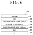
- FIG. 6 shows the configuration of a magneto-optical recording medium 12E according to a fifth preferred embodiment of the present invention.
- a base dielectric layer 14 formed of SiN
- a reproducing layer 39 formed of GdFeCo
- a recording layer 36 formed of TbFeCo
- a recording assist layer 38 formed of GdFeCo in this order.
- an overcoat layer 22 formed of SiN and a metal layer 24 containing Al in this order.
- the magneto-optical recording medium 12E is a dual-layer medium having the reproducing layer 39 and the recording layer 36.
- a manufacturing method for the magneto-optical recording medium 12C according to the third preferred embodiment shown in FIG. 4 will now be described in detail.
- a plurality of substrates 4 were prepared in the conditions that the distance (track pitch) between each land 8 and each groove 10 adjacent thereto in each substrate 4 was set to 0.40 ⁇ m and that the value of w2/w1 and the depth d of each groove 10 mentioned with reference to FIG. 1 were changed.
- a stationary opposed type sputtering device having a plurality of deposition chambers (sputter chambers) each capable of achieving an ultimate vacuum of 5 ⁇ 10 -5 Pa or less was prepared. First, each substrate was carried into the first chamber in which an Si target was mounted, and Ar gas and N2 gas were introduced into the first chamber to deposit the SiN layer 14 having a thickness of 40 nm on the substrate by reactive sputtering.
- the substrate was next moved into the second chamber in which a Gd 30 Fe 56 Co 14 alloy target was mounted, and Ar gas was introduced into the second chamber to deposit the first reproducing layer 26 formed of Gd 30 Fe 56 Co 14 having an RE rich composition (the compensation temperature is not lower than room temperature) by DC sputtering at room temperature.
- the Curie temperature of the first reproducing layer 26 is 300°C.
- the substrate was next moved into the third chamber in which a Gd target and an Fe target were mounted, and Ar gas was introduced into the third chamber to deposit the second reproducing layer 28 formed of GdFe by DC sputtering.
- the thickness of the first reproducing layer 26 was adjusted by adjusting the sputter time.
- the composition and thickness of the second reproducing layer 28 were adjusted by changing the applied power and deposition time for the Gd target and the Fe target.
- the Curie temperature of the second reproducing layer 28 was changed by adjusting the composition of Ge and Fe. Specifically, the content of Gd in the second reproducing layer 28 was changed in the range of 13 at% to 21 at%.
- the Curie temperature at the Gd content of 13 at% is 150°C
- the Curie temperature at the Gd content of 21 at% is 200°C.
- the substrate was next returned to the first chamber to deposit the SiN nonmagnetic block layer 30.
- the thickness of the SiN nonmagnetic block layer 30 was adjusted by changing the deposition time.
- the substrate was next moved into the fourth chamber in which a Tb 19 Fe 70 Co 11 alloy target was mounted, and Ar gas was introduced into the fourth chamber to deposit the recording layer 32 formed of Tb 19 Fe 70 Co 11 by DC sputtering.
- the thickness of the recording layer 32 was 50 nm.
- the Curie temperature of the recording layer 32 is 210°C.
- the substrate was next moved into the fifth chamber in which a Gd 20 Fe 64 Co 16 alloy target was mounted, and Ar gas was introduced into the fifth chamber to deposit the recording assist layer 34 formed of Gd 20 Fe 64 Co 16 by DC sputtering.
- the thickness of the recording assist layer 34 was 6 nm.
- the substrate was next returned to the first chamber to deposit the SiN overcoat layer 22.
- the substrate was next moved into the sixth chamber in which an AlTi alloy target containing 1.5 wt% of Ti was mounted to deposit the AlTi metal layer 24.
- the thicknesses of the overcoat layer 22 and the metal layer 24 were adjusted by changing the deposition time for each layer.
- a UV curing resin coating was formed on the metal layer 24 to obtain the magneto-optical recording medium 12C shown in FIG. 4.
- the deposition reference conditions for the magneto-optical recording medium 12C are shown in Table 1, and the CN ratios of two samples of the medium 12C using different substrates in groove shape and depth are shown in Table 2.
- the different groove shapes are shown in FIGS. 7 and 8.
- Medium Design Factors Deposition Reference Conditions Curie temperature of second reproducing layer (°C) 170 Thickness of first reproducing layer (nm) 30 Thickness of second reproducing layer (nm) 10 Thickness of nonmagnetic block layer (nm) 1 Thickness of overcoat layer (nm) 10 Thickness of Al layer (nm) 70 FIG. 8 FIG. 7 Groove shape Groove depth (nm) 6.0/10 29 8.5/10 49 CN ratio (Land) 45.8 42.2 CN ratio (Groove) 46.2 45.3
- FIGS. 9 and 10 show changes in the CN ratio with changes in w2/w1 under the condition where the groove depth d was fixed to 30 nm
- FIG. 10 shows changes in the CN ratio with changes in the groove depth d under the condition where w2/w1 was fixed to 0.6.
- the CN ratio rapidly decreases when w2/w1 is increased to form the groove shape into a nearly angular shape.
- the recorded mark is erased by a thermal effect in erasing on the adjacent tracks, thus reducing the CN ratio.
- the erasing power on the adjacent tracks was set to a power higher by 15% than the power capable of completely erasing the recorded mark.
- w2/w1 is set in the range of 0.4 to 0.8 to obtain the CN ratio of 45 dB or more.
- the groove depth d is set in the range of 25 to 45 nm to obtain the CN ratio of 45 dB or more.
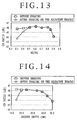
- FIGS. 11 to 14 More specifically, FIG. 11 shows the dependence of the CN ratio of the normal MO medium upon the value of w2/w1, and FIG. 12 shows the dependence of the CN ratio of the normal MO medium upon the groove depth d.
- FIG. 11 shows the dependence of the CN ratio of the normal MO medium upon the value of w2/w1
- FIG. 12 shows the dependence of the CN ratio of the normal MO medium upon the groove depth d.
- FIG. 13 shows the dependence of the CN ratio of the dual-layer MO medium upon the value of w2/w1
- FIG. 14 shows the dependence of the CN ratio of the dual-layer MO medium upon the groove depth d.
- w2/w1 is set in the range of 0.4 to 0.8 to obtain the CN ratio of 45 dB or more
- the groove depth d is set in the range of 25 to 45 nm to obtain the CN ratio of 45 dB or more.
- the radius of curvature of the edge portion of each land and each groove is set not so large. Even when the edge portion is formed as a merely chamfered portion, the crosstalk can be enough suppressed to improve the CN ratio.
- FIG. 15 shows changes in the CN ratio with changes in the Curie temperature of the second reproducing layer 28 by changing the Gd content in this layer 28.
- the CN ratio of 44 dB or more is obtained in the range of 160°C to 190°C for the Curie temperature of the second reproducing layer 28.
- FIG. 16 shows changes in the CN ratio with changes in the thickness of the first reproducing layer 26.
- the CN ratio rapidly decreases when the thickness of the first reproducing layer 26 is less than 25 nm, and gently decreases when the thickness of the layer 26 is greater than 30 nm. It is preferable that the thickness of the layer 26 is set to 35 nm or less to obtain the CN ratio of 44 dB or more. Further, the thickness of the second reproducing layer 28 depends on the thickness of the first reproducing layer 26. As apparent from FIG. 17, the CN ratio is improved in the range of 30% to 40% for the ratio of the thickness of the second reproducing layer 28 to the thickness of the first reproducing layer 26.
- FIG. 18 shows the dependence of the CN ratio upon the thickness of the nonmagnetic block layer 30.
- the thickness of the block layer 30 is less than 0.5 nm, the exchange coupling force between the recording layer 32 and the reproducing layers 26 and 28 rapidly increases to hinder the magnetostatic coupling force between the recording layer 32 and the reproducing layers 26 and 28, causing a rapid decrease in the CN ratio.
- the thickness of the nonmagnetic block layer 30 is set in the range of 0.5 to 2.0 nm to improve the CN ratio.
- FIG. 19 shows the dependence of the CN ratio upon the thickness of the overcoat layer 22.
- FIG. 20 shows the dependence of recording sensitivity upon the thickness of the overcoat layer 22.
- the CN ratio decreases with an increase in the thickness of the overcoat layer 22
- the recording power (Pw) decreases with an increase in the thickness of the overcoat layer 22.
- high-speed rotation is generally required to increase the transfer rate.
- the laser power required for recording becomes high.
- the blue laser suitable for high-density recording is lower in output than the red laser. Accordingly, it is required to minimize the recording power Pw to the medium for a higher linear velocity.
- the thickness of the overcoat layer 22 is set in the range of 5 to 15 nm to improve the CN ratio with a low recording power.
- FIG. 21 shows the dependence of the CN ratio upon the thickness of the AlTi layer 24, and FIG. 22 shows the dependence of recording sensitivity upon the thickness of the AlTi layer 24.
- the CN ratio increases with an increase in the thickness of the AlTi layer 24, and the recording power Pw also increases with an increase in the thickness of the AlTi layer 24. Accordingly, it is preferable that the thickness of the AlTi layer 24 is set in the range of 50 to 90 nm to improve the CN ratio with a low recording power.
- the optical disk drive shown in FIG. 23 is composed generally of a control unit 40 and an enclosure 41.
- the control unit 40 includes an MPU 42 for performing general control of the optical disk drive, a host interface 47 for exchanging commands and data between the optical disk drive and the host equipment, an optical disk controller (ODC) 44 for performing processing required for read/write of data on an optical disk medium, a digital signal processor (DSP) 46, and a buffer memory 48.
- the buffer memory 48 is used commonly for the MPU 42, the optical disk controller 44, and the host interface 47.
- the optical disk controller 44 includes a formatter 44a and an ECC processor 44b.
- the formatter 44a divides NRZ write data into the sectors of the medium to create a recording format.
- the ECC processor 44b creates an ECC code per sector write data and adds it to the recording format.
- the ECC processor 44b further creates a CRC code as required and adds it to the recording format. Further, the ECC processor 44b converts the sector data after ECC encoded into a 1-7RLL code, for example.
- the formatter 44a creates a logical block address (LBA) used in accessing from an OS.
- LBA is preliminarily programmed according to the recording capacity of the optical disk medium, and this program is preliminarily stored in the form of firmware in the formatter 44a.
- the formatter 44a further preliminarily stores a program for converting the LBA into a track address and a sector address. Further, a defective sector number found in performing physical formatting of the optical disk medium is also stored into the formatter 44a.
- sector read data demodulated is subjected to 1-7RLL inversion, and the ECC processor 44b performs CRC check and error detection and correction. Further, the formatter 44a links NRZ data in sectors and transfers a stream of NRZ read data to the host equipment.
- a write LSI circuit 50 is controlled by the optical disk controller 44.
- the write LSI circuit 50 has a write modulator 51 and a laser diode control circuit 52. An output from the laser diode control circuit 52 is supplied to a laser diode unit 60 provided in an optical unit of the enclosure 41.
- the laser diode unit 60 has a laser diode 60a and a monitoring photodetector 60b.
- the write modulator 51 converts write data into PPM recording or PWM recording format data.
- the optical disk drive of the present invention may use any one of different kinds of MO cartridge media having recording capacities of 128 MB, 230 MB, 540 MB, 640 MB, 1.3 GB, and the optical recording medium of the present invention. If the numerical aperture (NA) of the objective lens is not less than 0.55, the optical disk is downwardly compatible with the optical recording medium of the present invention by using a blue laser having a wavelength of 405 nm.
- NA numerical aperture
- the 128 MB and 230 MB MO cartridge media adopt pit position modulation (PPM) recording such that data is recorded according to the presence or absence of a mark on the medium.
- the recording format of the medium is CAV (constant angular velocity).
- the 540 MB, 640 MB, and 1.3 GB MO cartridge media capable of higher-density recording adopt pulse width modulation (PWM) recording such that data is recorded so as to correspond to the edges of a mark, i.e., the leading edge and trailing edge of a mark.
- PWM pulse width modulation
- the optical disk drive of the present invention can support various kinds of MO cartridge media having recording capacities of 128 MB, 230 MB, 540 MB, 640 MB, and 1.3 GB. Accordingly, when any one of these kinds of MO cartridge media is loaded into the optical disk drive, an ID portion formed as a plurality of prepits at a header portion of the medium is first read, and the kind of the medium is then recognized from the spacing of the prepits by the MPU 42, which in turn notifies the write LSI 50 of the result of this recognition. Further, when a CAD type MO cartridge is loaded into the optical disk drive, a predetermined value is set for this medium by the MPU 42, and this set value is supplied to the write LSI 50.
- the sector write data from the optical disk controller 44 is converted into PPM recording data by the write modulator 51
- the sector write data is converted into PWM recording data by the write modulator 51.
- the PPM recording data or PWM recording data obtained by the write modulator 51 is supplied to the laser diode control circuit 52, and the laser diode 60a is driven to write the data onto the medium.
- a read LSI circuit 54 has a read demodulator 55 and a frequency synthesizer 56.
- Return light from the medium irradiated with a laser beam output from the laser diode 60a is detected by an ID/MO detector 62, and is input as an ID signal and an MO signal through a head amplifier 64 into the read LSI circuit 54.
- Address information or the like at the header is detected as the ID signal, and a series of data on the identifier, track address, and sector address is reproduced to thereby allow recognition of the position of a beam spot on the medium.
- the read demodulator 55 in the read LSI circuit 54 is provided with circuit functions such as an AGC circuit, filter, and sector mark detecting circuit.
- the read demodulator 55 creates a read clock and read data from the input ID signal and the input MO signal, and demodulates the PPM recorded data or PWM recorded data to the original NRZ data.
- a zone CAV is adopted as the control of a spindle motor 70. Accordingly, the MPU 42 performs setting and control of a frequency dividing ratio for generation of a clock frequency corresponding to the zone, to the frequency synthesizer 56 incorporated in the read LSI circuit 54.
- the frequency synthesizer 56 is a PLL circuit having a programmable frequency divider, which generates a reference clock as a read clock having a predetermined inherent frequency according to a zone (band) position on the medium. More specifically, the frequency synthesizer 56 is configured by a PLL circuit having a programmable frequency divider, which generates a reference clock having a frequency fo according to a frequency dividing ratio (m/n) set according to a zone number by the MPU 42.
- the denominator n of the frequency dividing ratio (m/n) represents an inherent value according to the kind of the medium, i.e., 128 MB, 230 MB, 540 MB, 640 MB, 1.3 GB medium, or the optical recording medium of the present invention.
- the numerator m of the frequency dividing ratio (m/n) represents a value changing according to the zone position on the medium. This value is preliminarily stored as table information of values corresponding to zone numbers on each medium.
- the read LSI circuit 54 further outputs an MOXID signal E4 to the DSP 46.
- the MOXID signal E4 is a signal having an H level (bit 1) in an MO region as a data region and an L level (bit 0) in an ID region where the prepits are formed. That is, this signal indicates physical positions of the MO region and the ID region on the recording track of the medium.
- the read data demodulated in the read LSI 54 is supplied to the optical disk controller 44, and then undergoes 1-7RLL inversion and CRC check and ECC processing by the encoding function of the ECC processor 44b to restore the NRZ sector data. Further, the NRZ sector data is linked to the stream of the NRZ read data in the formatter 44a, and thereafter transferred through the buffer memory 48 and the host interface 47 to the host equipment.
- a detection signal from a temperature sensor 66 provided in the enclosure 41 is supplied through the DSP 46 to the MPU 42.
- the MPU 42 controls optimum values of read, write, and erase optical powers in the laser diode control circuit 52 according to an environmental temperature inside the disk drive detected by the temperature sensor 66.
- the laser diode control circuit 52 controls the write power to 6.0 mW, for example, and controls the read power to 2.0 mW, for example.
- Optical modulation recording is carried out for the 128 MB medium to the 1.3 GB medium, whereas both optical modulation recording and magnetic modulation recording may be adopted for the magneto-optical recording medium of the present invention.
- the MPU 42 further controls a spindle motor 70 provided in the enclosure 41 through the DSP 46 and a driver 68.
- the spindle motor 70 is driven to rotate the disk medium at a constant speed of 4500 rpm, for example.
- the linear velocity of the medium is 7.5 m/s both in recording data and in reproducing data.
- the MPU 42 further controls an electromagnet 74 provided in the enclosure 41 through the DSP 46 and a driver 72.
- the electromagnet 74 is located opposite to the beam irradiation side of the MO cartridge loaded into the disk drive, and functions to supply an external magnetic field to the medium.
- the DSP 46 has a servo function for positioning the laser beam from the laser diode 60a with respect to the medium, and includes a seek controller 57 for seeking the laser beam to a target track to position the beam spot on the target track and an on-track controller 58 for making the laser beam trace the center of the target track.
- an FES detector 75 for detecting the return light from the medium irradiated with the laser beam is provided in the optical unit in the enclosure 41, and an FES detecting circuit 76 produces a focus error signal from an output from the FES detector 75 to input the focus error signal into the DSP 46.
- a TES detector 77 for detecting the return light from the medium is provided in the optical unit in the enclosure 41, and a TES detecting circuit 78 produces a tracking error signal E1 from an output from the TES detector 77 to input the tracking error signal E1 into the DSP 46.
- the tracking error signal E1 is input into a TZC (Track Zero Cross) detecting circuit 80, in which a track zero cross pulse E2 is produced.
- the track zero cross pulse E2 from the TZC detecting circuit 80 is input into the DSP 46.
- the DSP 46 further controls to drive a focus actuator 90, lens actuator 94, and VCM 98 through drivers 88, 92, and 96, respectively, to control the position of the beam spot on the medium.
- FIG. 24 there is shown a schematic configuration of the enclosure 41 of the optical disk drive.
- the spindle motor 70 is provided in a housing 100.
- an MO cartridge 106 When an MO cartridge 106 is inserted into the housing 100 through an inlet door 104, the MO medium 12 in the MO cartridge 106 is chucked to a hub of a rotating shaft of the spindle motor 70, thus loading the MO medium 12.
- a carriage 108 is provided below the MO medium 12 loaded into the disk drive so as to be movable across the tracks of the MO medium 12 by the VCM 98.
- An objective lens 110 and a beam raising prism 114 are mounted on the carriage 108.
- the laser beam from the laser diode 60a provided in a fixed optical system 112 is reflected by the beam raising prism 114 to enter the objective lens 110.
- the laser beam is focused by the objective lens 110 onto the recording surface of the MO medium 12.
- the objective lens 110 is controlled to move along its optical axis by the focus actuator 90 in the enclosure 41 shown in FIG. 23.
- the objective lens 110 is further controlled to move across a given number of tracks (e.g., tens of tracks) of the MO medium 12, i.e., in the radial direction thereof, by the track actuator 94 in the enclosure 41 shown in FIG. 23.
- An electromagnet 102 for applying an external magnetic field to the MO medium 12 is provided above the MO medium 12 loaded into the disk drive.
- an optical recording medium having lands and grooves as recording tracks which can improve the CN ratio and obtain enough small crosstalk characteristics even in the case of using a blue laser having a small beam spot for recording/reproduction of data. Further, it is possible to provide an optical disk drive suitable for recording/reproduction of data to/from such an optical recording medium.
Abstract
An optical recording medium having recording tracks
consisting of a plurality of lands and a plurality of
grooves, wherein the diameter of a laser beam to be used
for recording/reproduction on a recording surface of the
medium is 0.7 µm or less. The optical recording medium
includes a transparent substrate on which the lands and
the grooves are alternately formed and an optically
recordable recording layer provided on the transparent
substrate. The width w1 of each land at the center of the
height of the boundary between each land and each groove
adjacent thereto, the width w2 of a flat top surface of
each land, and the depth d of each groove are set to 0.4
≦ w2/w1 ≦ 0.8 and 25 nm ≦ d ≦ 45 nm. At least each land
has an edge portion formed as a curved surface.
Description
The present invention relates generally to an
optical recording medium, and more particularly to a
land/groove recording type magneto-optical recording
medium.
A method of shortening the wavelength of a laser to
be used in recording or reproducing data is investigated
as one method for increasing a recording density on an
optical disk. For example, the wavelength of a laser used
in a 3.5-inch magneto-optical disk drive at present is
650 nm. By using a blue laser having a wavelength of 405
nm instead, the diameter of a beam spot on a recording
surface of the disk can be reduced from about 1.0 µm to
0.65 µm, thereby allowing high-density recording.
A magneto-optical disk is known as a high-density
recording medium, and an increase in its recording
density is demanded with an increase in quantity of
information. Increasing the recording density of the
medium can be realized by shortening the space between
adjacent recording marks. However, the reproduction of
each recording mark is limited by the size of a light
beam (beam spot) on the medium. In the case that the
density of the recording marks is set so that only one
recording mark is present inside the beam spot, an output
waveform corresponding to "1" or "0" can be observed as a
reproduced signal according to whether or not the
recording mark is present inside the beam spot.
However, in the case that the density of the
recording marks is increased so that a plurality of
recording marks are present inside the beam spot, the
reproduced output does not change irrespective of
movement of the beam spot on the medium, so that the
output waveform becomes linear and the presence or
absence of recording marks cannot be distinguished. The
reproduction of such small recording marks having a
period shorter than the size of the beam spot may be
effected by reducing the size of the beam spot. However,
the size of the beam spot is limited by the wavelength λ
of light output from a light source and the numerical
aperture NA of an objective lens, so that the spot size
cannot be sufficiently reduced.
Recently commercially available is a magneto-optical
disk drive adopting a reproducing method using a
magnetically induced super-resolution (MSR) technique for
reproducing a recording mark smaller than the size of the
beam spot by the use of an existing optical system. The
MSR is a reproducing method such that while one mark
present inside the beam spot is being reproduced, another
mark is masked to thereby increase a reproductive
resolution. Accordingly, such an MSR medium requires at
least a mask layer or reproducing layer for masking the
other mark so that the one mark is reproduced during
signal reproduction, in addition to a recording layer for
recording marks.
For example, there has been proposed a CAD (center
aperture detection) type MSR medium such that a
nonmagnetic layer is interposed between a reproducing
layer and a recording layer, and a recorded mark in the
recording layer is transferred to the reproducing layer
by magnetostatic coupling to thereby reproduce
information. A longitudinally magnetized film having an
axis of easy magnetization in a longitudinal direction at
room temperature is used as the reproducing layer, and
the recorded mark in the recording layer at only a
portion heated to a high temperature by the irradiation
with a laser beam is transferred to the reproducing layer
to thereby mask the other portion except the above heated
portion for reproduction by means of the reproducing
layer, thus allowing super-resolution reproduction. In
the CAD medium, longitudinal magnetization in the
reproducing layer at the other portion except the
aperture portion is not detected, and it is resistant
against crosstalk from the adjacent track, thereby
allowing a reduction in track pitch.
In recent years, the development for reducing the
beam diameter has become active by using a short-wavelength
laser or a high-NA lens as means for realizing
the high recording density on an optical disk. For
example, in an optical system of an existing magneto-optical
disk drive using a laser beam having a wavelength
of 650 nm and a lens having a numerical aperture NA of
0.55, the beam spot diameter is about 1.0 µm (1/e2).
However, by using a laser beam having a wavelength of 405
nm with the same lens having a numerical aperture NA of
0.55, the beam spot diameter can be reduced to about 0.65
µm. Reducing the beam spot diameter can improve a
resolution, so that a small mark can be recorded to
thereby increase the recording density. By changing the
wavelength of the laser beam from 650 nm to 405 nm, both
the mark length and the track pitch can be reduced and
the recording density can therefore be expected to
increase about 2.5 times.
However, in the case of applying the conventional
CAD medium using a laser beam having a wavelength of 650
nm to the recording/reproduction with a laser beam having
a wavelength of 405 nm, there has occurred a problem that
a sufficient recording/reproduction signal quality cannot
be obtained with a wavelength-converted mark length. For
example, while the CAD medium using a laser beam having a
wavelength of 650 nm is now in practical use, a CN ratio
of about 45 dB is obtained with a shortest mark length of
0.40 µm. By using a laser beam having a wavelength of
405 nm, a CN ratio of about 45 dB should be obtained with
a mark length of 0.25 µm in terms of beam diameter.
Actually, however, there is a problem that a low CN ratio
of about 42 dB is obtained with a mark length of 0.25 µm
even in the case of using a laser beam having a
wavelength of 405 nm. In a magneto-optical recording
medium using lands and grooves as recording tracks, the
above problem remarkably appears on the lands. Further,
also in a general magneto-optical recording medium as
well as the above CAD type magneto-optical recording
medium, it has become apparent that a sufficient CN ratio
cannot be obtained in reproducing information on the
lands in the case of using a blue laser beam having a
wavelength of 405 nm.
It is therefore an object of the present invention
to provide an optical recording medium which can realize
good recording/reproduction characteristics both on the
lands and on the grooves in a small beam diameter
obtained by using a short-wavelength laser.
It is another object of the present invention to
provide an optical storage device which can realize a
good reproduction characteristic both on the lands and on
the grooves in a small beam diameter obtained by using a
short-wavelength laser.
In accordance with an aspect of the present
invention, there is provided an optical recording medium
having recording tracks consisting of a plurality of
lands and a plurality of grooves, wherein the diameter of
a laser beam to be used for recording/reproduction on a
recording surface of the medium is 0.7 µm or less, the
optical recording medium comprising a transparent
substrate on which the lands and the grooves are
alternately formed; and an optically recordable recording
layer provided on the transparent substrate; the width w1
of each land at the center of the height of the boundary
between each land and each groove adjacent thereto, the
width w2 of a flat top surface of each land, and the
depth d of each groove being set to 0.4 ≦ w2/w1 ≦ 0.8 and
25 nm ≦ d ≦ 45 nm; at least each land having an edge
portion formed as a curved surface.
Preferably, each groove has an edge portion formed
as a curved surface, and the recording layer comprises a
magneto-optical recording layer formed of a rare earth-transition
metal composite material.
In accordance with another aspect of the present
invention, there is provided a magneto-optical recording
medium having recording tracks consisting of a plurality
of lands and a plurality of grooves, wherein the diameter
of a laser beam to be used for recording/reproduction on
a recording surface of the medium is 0.7 µm or less, the
magneto-optical recording medium comprising a transparent
substrate on which the lands and the grooves are
alternately formed; a reproducing layer provided on the
transparent substrate and formed of a rare earth-transition
metal composite material having a relatively
large Kerr rotation angle and a relatively small
coercivity at room temperature; and a recording layer
provided on the reproducing layer and formed of a rare
earth-transition metal composite material having a
relatively small Kerr rotation angle and a relatively
large coercivity at room temperature; the width w1 of
each land at the center of the height of the boundary
between each land and each groove adjacent thereto, the
width w2 of a flat top surface of each land, and the
depth d of each groove being set to 0.4 ≦ w2/w1 ≦ 0.8 and
25 nm ≦ d ≦ 45 nm; at least each land having an edge
portion formed as a curved surface.
In accordance with a further aspect of the present
invention, there is provided a magneto-optical recording
medium having recording tracks consisting of a plurality
of lands and a plurality of grooves, wherein the diameter
of a laser beam to be used for recording/reproduction on
a recording surface of the medium is 0.7 µm or less, the
magneto-optical recording medium comprising a transparent
substrate on which the lands and the grooves are
alternately formed; a first reproducing layer provided on
the transparent substrate and having an axis of easy
magnetization in a longitudinal direction at room
temperature; a second reproducing layer provided on the
first reproducing layer and having an axis of easy
magnetization in a longitudinal direction at room
temperature; a nonmagnetic block layer provided on the
second reproducing layer; a recording layer provided on
the nonmagnetic block layer and having an axis of easy
magnetization in a perpendicular direction at room
temperature in the case of a single layer; a nonmagnetic
overcoat layer provided on the recording layer; and a
metal layer provided on the nonmagnetic overcoat layer;
the width w1 of each land at the center of the height of
the boundary between each land and each groove adjacent
thereto, the width w2 of a flat top surface of each land,
and the depth d of each groove being set to 0.4 ≦ w2/w1 ≦
0.8 and 25 nm ≦ d ≦ 45 nm; at least each land having an
edge portion formed as a curved surface.
Preferably, the first and second reproducing layers
respectively have Curie temperatures Tc1 and Tc2 set to
Tc2 ≦ Tc1 and 160°C ≦ Tc2 ≦ 190°C.
Preferably, the first reproducing layer has a
thickness tr1 of 25 to 35 nm, and the second reproducing
layer has a thickness tr2 set to tr1 × 0.3 ≦ tr2 ≦ tr1 ×
0.4.
Preferably, the nonmagnetic overcoat layer has a
thickness of 5 to 15 nm, the metal layer has a thickness
of 50 to 90 nm, and the nonmagnetic block layer has a
thickness of 0.5 to 2 nm.
In accordance with a still further aspect of the
present invention, there is provided an optical storage
device capable of at least reading information recorded
on an optical recording medium having recording tracks
consisting of a plurality of lands and a plurality of
grooves, the optical storage device comprising an optical
head for irradiating the optical recording medium with a
laser beam having a diameter of 0.7 µm or less on a
recording surface of the medium; and a photodetector for
generating a reproduction signal from reflected light
reflected on the optical recording medium; the optical
recording medium comprising a transparent substrate on
which the lands and the grooves are alternately formed
and an optically recordable recording layer provided on
the transparent substrate; the width w1 of each land at
the center of the height of the boundary between each
land and each groove adjacent thereto, the width w2 of a
flat top surface of each land, and the depth d of each
groove being set to 0.4 ≦ w2/w1 ≦ 0.8 and 25 nm ≦ d ≦ 45
nm; at least each land having an edge portion formed as a
curved surface.
Referring to FIG. 1, there is shown a partially
cutaway, sectional view of a land/groove recording type
optical storage medium according to the present invention.
The optical storage medium 2 usually has the form of a
disk. Reference numeral 4 denotes a transparent substrate
formed of glass or polycarbonate, for example. The
substrate 4 has a plurality of lands 8 and a plurality of
grooves 10 alternately formed. The center distance (track
pitch) between any adjacent ones of the lands 8 and the
grooves 10 of the substrate 4 is 0.40 µm, for example,
and a recording layer 6 is formed on the substrate 4. The
level difference between the lands 8 and the grooves 10
of the substrate 4 is 35 nm, for example. It is
sufficient that the optical storage medium 2 applicable
to the present invention is an optical storage medium
having at least a land and a groove as recording tracks.
As the recording layer 6, a magneto-optical recording
layer or a phase-change type recording layer may be
adopted, for example.
Each land 8 has a pair of edge portions 8a on the
opposite sides, and each edge portion 8a is formed as a
curved surface having a predetermined radius of curvature.
Similarly, each groove 10 has a pair of edge portions 10a
on the opposite sides, and each edge portion 10a is
formed as a curved surface having a predetermined radius
of curvature. As hereinafter described in detail, the
width w1 of each land 8 at the center of the height of
the boundary between each land 8 and each groove 10
adjacent thereto, the width w2 of a flat top surface of
each land 8, and the depth d of each groove 10 are
preferably set as follows:
0.4 ≦ w2/w1 ≦ 0.8 and 25 nm ≦ d ≦ 45 nm
In manufacturing such an optical storage medium, a
groove and pits are preliminarily formed on a transparent
substrate. Specifically, a stamper having a positive
resist film is used and it is exposed to a laser beam at
a portion except a portion corresponding to the groove
and the pits. Then, the portion corresponding to the
groove and the pits is formed into a projecting portion
by development and etching. At this time, the etching is
performed by ion milling, sputtering, or the like to
provide a predetermined curvature at a portion
corresponding to the edge portions of each land and the
edge portions of each groove. Then, the stamper thus
prepared is mounted on a die of an injection molding
machine, and a resin such as polycarbonate is supplied to
the injection molding machine to thereby prepare the
transparent substrate 4 of the optical storage medium
which has a plurality of lands 8 and a plurality of
grooves 10 alternately formed. Thereafter, a recording
layer, protective layer, and reflective layer are formed
on a transfer surface (a surface formed with the groove
and the pits) of the transparent substrate 4 to thereby
complete the optical storage medium. A manufacturing
method for such a substrate is described in Japanese
Patent Laid-open No. Hei 11-232707, for example.
FIG. 2 shows the configuration of a magneto-optical
recording medium 12A according to a first preferred
embodiment of the present invention. Provided on the
transparent substrate 4 shown in FIG. 1 are a base
dielectric layer 14 formed of SiN, a reproducing layer 16
formed of GdFeCo, a nonmagnetic layer 18 formed of SiN,
and a recording layer 20 formed of TbFeCo in this order.
Further provided on the recording layer 20 are an
overcoat layer 22 formed of SiN and a metal layer 24
containing Al in this order. The magneto-optical
recording medium 12A according to this preferred
embodiment is a CAD (center aperture detection) type
magnetically induced super-resolution (MSR) medium such
that a recorded mark in the recording layer 20 is
transferred to the reproducing layer 16 by magnetostatic
coupling. The reproducing layer 16 has a relatively large
Kerr rotation angle and a relatively small coercivity at
room temperature as compared with the recording layer 20.
In contrast, the recording layer 20 has a relatively
small Kerr rotation angle and a relatively large
coercivity at room temperature as compared with the
reproducing layer 16.
FIG. 3 shows the configuration of a magneto-optical
recording medium 12B according to a second preferred
embodiment of the present invention. Provided on the
transparent substrate 4 shown in FIG. 1 are a base
dielectric layer 14 formed of SiN, a first reproducing
layer 26 formed of GdFeCo, a second reproducing layer 28
formed of GdFe, a nonmagnetic layer 30 formed of SiN, and
a recording layer 32 formed of TbFeCo in this order.
Further provided on the recording layer 32 are an
overcoat layer 22 formed of SiN and a metal layer 24
containing Al in this order. The metal layer 24 may be
formed of a material containing Au, Cu, or Ag as a
principal component. The magneto-optical recording medium
12B according to this preferred embodiment is also a CAD
type MSR medium such that a recorded mark in the
recording layer 32 is transferred to the second
reproducing layer 28 and the first reproducing layer 26
by magnetostatic coupling. Each of the first reproducing
layer 26 and the second reproducing layer 28 has an axis
of easy magnetization in the longitudinal direction at
room temperature. In contrast, the recording layer 32 has
an axis of easy magnetization in the perpendicular
direction at room temperature in the case of a single
layer.
FIG. 4 shows the configuration of a magneto-optical
recording medium 12C according to a third preferred
embodiment of the present invention. Provided on the
transparent substrate 4 shown in FIG. 1 are a base
dielectric layer 14 formed of SiN, a first reproducing
layer 26 formed of GdFeCo, a second reproducing layer 28
formed of GdFe, a nonmagnetic layer 30 formed of SiN, and
a recording layer 32 formed of TbFeCo in this order.
Further provided on the recording layer 32 are a
recording assist layer 34 formed of GdFeCo, an overcoat
layer 22 formed of SiN, and a metal layer 24 containing
Al in this order. The magneto-optical recording medium
12C according to this preferred embodiment is also a CAD
type MSR medium such that a recorded mark in the
recording layer 32 is transferred to the second
reproducing layer 28 and the first reproducing layer 26
by magnetostatic coupling. Each of the first reproducing
layer 26 and the second reproducing layer 28 has an axis
of easy magnetization in the longitudinal direction at
room temperature. In contrast, the recording layer 32 has
an axis of easy magnetization in the perpendicular
direction at room temperature in the case of a single
layer.
FIG. 5 shows the configuration of a magneto-optical
recording medium 12D according to a fourth preferred
embodiment of the present invention. Provided on the
transparent substrate 4 shown in FIG. 1 are a base
dielectric layer 14 formed of SiN, a recording layer 36
formed of TbFeCo, a recording assist layer 38 formed of
GdFeCo, an overcoat layer 22 formed of SiN, and a metal
layer 24 containing Al in this order. The magneto-optical
recording medium 12D according to this preferred
embodiment is a normal type magneto-optical recording
medium.
FIG. 6 shows the configuration of a magneto-optical
recording medium 12E according to a fifth preferred
embodiment of the present invention. Provided on the
transparent substrate 4 shown in FIG. 1 are a base
dielectric layer 14 formed of SiN, a reproducing layer 39
formed of GdFeCo, a recording layer 36 formed of TbFeCo,
and a recording assist layer 38 formed of GdFeCo in this
order. Further provided on the recording assist layer 38
are an overcoat layer 22 formed of SiN and a metal layer
24 containing Al in this order. The magneto-optical
recording medium 12E is a dual-layer medium having the
reproducing layer 39 and the recording layer 36.
A manufacturing method for the magneto-optical
recording medium 12C according to the third preferred
embodiment shown in FIG. 4 will now be described in
detail. A plurality of substrates 4 were prepared in the
conditions that the distance (track pitch) between each
land 8 and each groove 10 adjacent thereto in each
substrate 4 was set to 0.40 µm and that the value of
w2/w1 and the depth d of each groove 10 mentioned with
reference to FIG. 1 were changed. A stationary opposed
type sputtering device having a plurality of deposition
chambers (sputter chambers) each capable of achieving an
ultimate vacuum of 5 × 10⁻⁵ Pa or less was prepared.
First, each substrate was carried into the first chamber
in which an Si target was mounted, and Ar gas and N2 gas
were introduced into the first chamber to deposit the SiN
layer 14 having a thickness of 40 nm on the substrate by
reactive sputtering.
The substrate was next moved into the second
chamber in which a Gd30Fe56Co14 alloy target was mounted,
and Ar gas was introduced into the second chamber to
deposit the first reproducing layer 26 formed of
Gd30Fe56Co14 having an RE rich composition (the
compensation temperature is not lower than room
temperature) by DC sputtering at room temperature. The
Curie temperature of the first reproducing layer 26 is
300°C. The substrate was next moved into the third
chamber in which a Gd target and an Fe target were
mounted, and Ar gas was introduced into the third chamber
to deposit the second reproducing layer 28 formed of GdFe
by DC sputtering. The thickness of the first reproducing
layer 26 was adjusted by adjusting the sputter time. The
composition and thickness of the second reproducing layer
28 were adjusted by changing the applied power and
deposition time for the Gd target and the Fe target. The
Curie temperature of the second reproducing layer 28 was
changed by adjusting the composition of Ge and Fe.
Specifically, the content of Gd in the second reproducing
layer 28 was changed in the range of 13 at% to 21 at%.
The Curie temperature at the Gd content of 13 at% is 150°C,
and the Curie temperature at the Gd content of 21 at% is
200°C.
The substrate was next returned to the first
chamber to deposit the SiN nonmagnetic block layer 30.
The thickness of the SiN nonmagnetic block layer 30 was
adjusted by changing the deposition time. The substrate
was next moved into the fourth chamber in which a
Tb19Fe70Co11 alloy target was mounted, and Ar gas was
introduced into the fourth chamber to deposit the
recording layer 32 formed of Tb19Fe70Co11 by DC sputtering.
The thickness of the recording layer 32 was 50 nm. The
Curie temperature of the recording layer 32 is 210°C. The
substrate was next moved into the fifth chamber in which
a Gd20Fe64Co16 alloy target was mounted, and Ar gas was
introduced into the fifth chamber to deposit the
recording assist layer 34 formed of Gd20Fe64Co16 by DC
sputtering. The thickness of the recording assist layer
34 was 6 nm.
The substrate was next returned to the first
chamber to deposit the SiN overcoat layer 22. The
substrate was next moved into the sixth chamber in which
an AlTi alloy target containing 1.5 wt% of Ti was mounted
to deposit the AlTi metal layer 24. The thicknesses of
the overcoat layer 22 and the metal layer 24 were
adjusted by changing the deposition time for each layer.
Finally, a UV curing resin coating was formed on the
metal layer 24 to obtain the magneto-optical recording
medium 12C shown in FIG. 4.
The deposition reference conditions for the
magneto-optical recording medium 12C are shown in Table 1,
and the CN ratios of two samples of the medium 12C using
different substrates in groove shape and depth are shown
in Table 2. The different groove shapes are shown in FIGS.
7 and 8.
| Medium Design Factors | Deposition Reference Conditions |
| Curie temperature of second reproducing layer (°C) | 170 |
| Thickness of first reproducing layer (nm) | 30 |
| Thickness of second reproducing layer (nm) | 10 |
| Thickness of nonmagnetic block layer (nm) | 1 |
| Thickness of overcoat layer (nm) | 10 |
| Thickness of Al layer (nm) | 70 |
| FIG. 8 | FIG. 7 | |
| Groove shape Groove depth (nm) | 6.0/10 29 | 8.5/10 49 |
| CN ratio (Land) | 45.8 | 42.2 |
| CN ratio (Groove) | 46.2 | 45.3 |
Optical modulation recording was applied to the
magneto-optical recording medium 12C by using a laser
beam having a wavelength of 405 nm (NA of the objective
lens = 0.55) under the conditions that the length of each
recording mark was 0.25 µm and the linear velocity of the
medium was 7.5 m/s. Then, the CN ratios of the two
samples were measured by a spectral analyzer. As apparent
from Table 2, the CN ratio of each land of the sample
having angular grooves shown in FIG. 7 is as low as about
42 dB, whereas the CN ratio of each land of the sample
having round or curved grooves shown in FIG. 8 is as high
as about 46 dB. The difference in groove shape was
obtained by changing the time of UV irradiation to the
substrate surface.
Various samples were prepared by fixing the
deposition conditions shown in Table 1 and changing the
value of w2/w1 of the substrate and the groove depth d.
The results of measurement of the CN ratio of each land
are shown in FIGS. 9 and 10. FIG. 9 shows changes in the
CN ratio with changes in w2/w1 under the condition where
the groove depth d was fixed to 30 nm, and FIG. 10 shows
changes in the CN ratio with changes in the groove depth
d under the condition where w2/w1 was fixed to 0.6. As
apparent from FIG. 9, the CN ratio rapidly decreases when
w2/w1 is increased to form the groove shape into a nearly
angular shape. Conversely, when w2/w1 is decreased, the
recorded mark is erased by a thermal effect in erasing on
the adjacent tracks, thus reducing the CN ratio. The
erasing power on the adjacent tracks was set to a power
higher by 15% than the power capable of completely
erasing the recorded mark. As understood from FIG. 9, it
is preferable that w2/w1 is set in the range of 0.4 to
0.8 to obtain the CN ratio of 45 dB or more. Further, as
understood from FIG. 10, it is preferable that the groove
depth d is set in the range of 25 to 45 nm to obtain the
CN ratio of 45 dB or more.
Similar tests were made on the normal magneto-optical
recording medium 12D having no reproducing layer
shown in FIG. 5 and the dual-layer magneto-optical
recording medium 12E having the reproducing layer 39 and
the recording layer 36 shown in FIG. 6. The deposition
conditions of each layer of the media shown in FIGS. 5
and 6 are similar to those for the CAD medium shown in
FIG. 4. Similar measurements were made under the
condition where the length of a recorded mark was set to
0.45 µm. The results of these measurements are shown in
FIGS. 11 to 14. More specifically, FIG. 11 shows the
dependence of the CN ratio of the normal MO medium upon
the value of w2/w1, and FIG. 12 shows the dependence of
the CN ratio of the normal MO medium upon the groove
depth d. FIG. 13 shows the dependence of the CN ratio of
the dual-layer MO medium upon the value of w2/w1, and FIG.
14 shows the dependence of the CN ratio of the dual-layer
MO medium upon the groove depth d. As apparent from FIGS.
11 to 14, the results of measurements on the normal MO
medium and the dual-layer MO medium 12E are almost
similar to those on the CAD medium 12C shown in FIG. 4.
More specifically, it is preferable that w2/w1 is set in
the range of 0.4 to 0.8 to obtain the CN ratio of 45 dB
or more, and it is preferable that the groove depth d is
set in the range of 25 to 45 nm to obtain the CN ratio of
45 dB or more. Further, it is preferable that the radius
of curvature of the edge portion of each land and each
groove is set not so large. Even when the edge portion is
formed as a merely chamfered portion, the crosstalk can
be enough suppressed to improve the CN ratio.
Further, various samples were prepared by using a
substrate with the groove depth d set to 30 nm and w2/w1
set to 6/10 and changing the medium design factors shown
in Table 1, and these samples were used to measure the CN
ratio on each land. The reference conditions according to
the present invention and the conventional conditions are
compared in Table 3.
| Medium Design Factors | Reference Conditions | Conventional Conditions |
| Curie temperature of second reproducing layer (°C) | 170 | 140 |
| Thickness of first reproducing layer (nm) | 30 | 30 |
| Thickness of second reproducing layer (nm) | 10 | 6 |
| Thickness of nonmagnetic block layer (nm) | 1 | 2 |
| Thickness of Overcoat layer (nm) | 10 | 20 |
| Thickness of Al layer (nm) | 70 | 40 |
FIG. 15 shows changes in the CN ratio with changes
in the Curie temperature of the second reproducing layer
28 by changing the Gd content in this layer 28. As
apparent from FIG. 15, the CN ratio of 44 dB or more is
obtained in the range of 160°C to 190°C for the Curie
temperature of the second reproducing layer 28. FIG. 16
shows changes in the CN ratio with changes in the
thickness of the first reproducing layer 26. FIG. 17
shows changes in the CN ratio with changes in second
reproducing layer thickness ratio (%) (= the thickness of
the second reproducing layer 28/the thickness of the
first reproducing layer 26). As apparent from FIG. 16,
the CN ratio rapidly decreases when the thickness of the
first reproducing layer 26 is less than 25 nm, and gently
decreases when the thickness of the layer 26 is greater
than 30 nm. It is preferable that the thickness of the
layer 26 is set to 35 nm or less to obtain the CN ratio
of 44 dB or more. Further, the thickness of the second
reproducing layer 28 depends on the thickness of the
first reproducing layer 26. As apparent from FIG. 17, the
CN ratio is improved in the range of 30% to 40% for the
ratio of the thickness of the second reproducing layer 28
to the thickness of the first reproducing layer 26.
FIG. 18 shows the dependence of the CN ratio upon
the thickness of the nonmagnetic block layer 30. When the
thickness of the block layer 30 is less than 0.5 nm, the
exchange coupling force between the recording layer 32
and the reproducing layers 26 and 28 rapidly increases to
hinder the magnetostatic coupling force between the
recording layer 32 and the reproducing layers 26 and 28,
causing a rapid decrease in the CN ratio. Conversely,
when the thickness of the nonmagnetic block layer 30 is
large, the magnetostatic coupling force decreases to
cause a reduction in transferability of the recorded mark,
thus resulting a decrease in the CN ratio. Therefore, it
is preferable that the thickness of the nonmagnetic block
layer 30 is set in the range of 0.5 to 2.0 nm to improve
the CN ratio.
FIG. 19 shows the dependence of the CN ratio upon
the thickness of the overcoat layer 22. FIG. 20 shows the
dependence of recording sensitivity upon the thickness of
the overcoat layer 22. As apparent from FIGS. 19 and 20,
the CN ratio decreases with an increase in the thickness
of the overcoat layer 22, and the recording power (Pw)
decreases with an increase in the thickness of the
overcoat layer 22. In optical recording, high-speed
rotation is generally required to increase the transfer
rate. However, when a high rotational speed is set to
increase the linear velocity, the laser power required
for recording becomes high. In particular, the blue laser
suitable for high-density recording is lower in output
than the red laser. Accordingly, it is required to
minimize the recording power Pw to the medium for a
higher linear velocity. As apparent from FIGS. 19 and 20,
it is preferable that the thickness of the overcoat layer
22 is set in the range of 5 to 15 nm to improve the CN
ratio with a low recording power.
FIG. 21 shows the dependence of the CN ratio upon
the thickness of the AlTi layer 24, and FIG. 22 shows the
dependence of recording sensitivity upon the thickness of
the AlTi layer 24. As apparent from FIGS. 21 and 22, the
CN ratio increases with an increase in the thickness of
the AlTi layer 24, and the recording power Pw also
increases with an increase in the thickness of the AlTi
layer 24. Accordingly, it is preferable that the
thickness of the AlTi layer 24 is set in the range of 50
to 90 nm to improve the CN ratio with a low recording
power.
Referring to FIG. 23, there is shown a circuit
block diagram of an optical disk drive according to the
present invention. The optical disk drive shown in FIG.
23 is composed generally of a control unit 40 and an
enclosure 41. The control unit 40 includes an MPU 42 for
performing general control of the optical disk drive, a
host interface 47 for exchanging commands and data
between the optical disk drive and the host equipment, an
optical disk controller (ODC) 44 for performing
processing required for read/write of data on an optical
disk medium, a digital signal processor (DSP) 46, and a
buffer memory 48. The buffer memory 48 is used commonly
for the MPU 42, the optical disk controller 44, and the
host interface 47.
The optical disk controller 44 includes a formatter
44a and an ECC processor 44b. In write access, the
formatter 44a divides NRZ write data into the sectors of
the medium to create a recording format. The ECC
processor 44b creates an ECC code per sector write data
and adds it to the recording format. The ECC processor
44b further creates a CRC code as required and adds it to
the recording format. Further, the ECC processor 44b
converts the sector data after ECC encoded into a 1-7RLL
code, for example.
The formatter 44a creates a logical block address
(LBA) used in accessing from an OS. The LBA is
preliminarily programmed according to the recording
capacity of the optical disk medium, and this program is
preliminarily stored in the form of firmware in the
formatter 44a. The formatter 44a further preliminarily
stores a program for converting the LBA into a track
address and a sector address. Further, a defective sector
number found in performing physical formatting of the
optical disk medium is also stored into the formatter 44a.
In read access, sector read data demodulated is
subjected to 1-7RLL inversion, and the ECC processor 44b
performs CRC check and error detection and correction.
Further, the formatter 44a links NRZ data in sectors and
transfers a stream of NRZ read data to the host equipment.
A write LSI circuit 50 is controlled by the optical disk
controller 44. The write LSI circuit 50 has a write
modulator 51 and a laser diode control circuit 52. An
output from the laser diode control circuit 52 is
supplied to a laser diode unit 60 provided in an optical
unit of the enclosure 41.
The laser diode unit 60 has a laser diode 60a and a
monitoring photodetector 60b. The write modulator 51
converts write data into PPM recording or PWM recording
format data. As an optical disk for performing
recording/reproduction by using the laser diode unit 60,
i.e., a rewritable magneto-optical (MO) cartridge medium,
the optical disk drive of the present invention may use
any one of different kinds of MO cartridge media having
recording capacities of 128 MB, 230 MB, 540 MB, 640 MB,
1.3 GB, and the optical recording medium of the present
invention. If the numerical aperture (NA) of the
objective lens is not less than 0.55, the optical disk is
downwardly compatible with the optical recording medium
of the present invention by using a blue laser having a
wavelength of 405 nm.
Of these MO cartridge media, the 128 MB and 230 MB
MO cartridge media adopt pit position modulation (PPM)
recording such that data is recorded according to the
presence or absence of a mark on the medium. Further, the
recording format of the medium is CAV (constant angular
velocity). On the other hand, the 540 MB, 640 MB, and 1.3
GB MO cartridge media capable of higher-density recording
adopt pulse width modulation (PWM) recording such that
data is recorded so as to correspond to the edges of a
mark, i.e., the leading edge and trailing edge of a mark.
Further, a zone CAV is adopted as the recording format of
the medium.
Thus, the optical disk drive of the present
invention can support various kinds of MO cartridge media
having recording capacities of 128 MB, 230 MB, 540 MB,
640 MB, and 1.3 GB. Accordingly, when any one of these
kinds of MO cartridge media is loaded into the optical
disk drive, an ID portion formed as a plurality of
prepits at a header portion of the medium is first read,
and the kind of the medium is then recognized from the
spacing of the prepits by the MPU 42, which in turn
notifies the write LSI 50 of the result of this
recognition. Further, when a CAD type MO cartridge is
loaded into the optical disk drive, a predetermined value
is set for this medium by the MPU 42, and this set value
is supplied to the write LSI 50.
In the case of the 128 MB or 230 MB medium, the
sector write data from the optical disk controller 44 is
converted into PPM recording data by the write modulator
51, whereas in the case of the 540 MB, 640 MB, 1.3 GB
medium, or the optical recording medium of the present
invention, the sector write data is converted into PWM
recording data by the write modulator 51. The PPM
recording data or PWM recording data obtained by the
write modulator 51 is supplied to the laser diode control
circuit 52, and the laser diode 60a is driven to write
the data onto the medium.
A read LSI circuit 54 has a read demodulator 55 and
a frequency synthesizer 56. Return light from the medium
irradiated with a laser beam output from the laser diode
60a is detected by an ID/MO detector 62, and is input as
an ID signal and an MO signal through a head amplifier 64
into the read LSI circuit 54. Address information or the
like at the header is detected as the ID signal, and a
series of data on the identifier, track address, and
sector address is reproduced to thereby allow recognition
of the position of a beam spot on the medium.
The read demodulator 55 in the read LSI circuit 54
is provided with circuit functions such as an AGC circuit,
filter, and sector mark detecting circuit. The read
demodulator 55 creates a read clock and read data from
the input ID signal and the input MO signal, and
demodulates the PPM recorded data or PWM recorded data to
the original NRZ data. A zone CAV is adopted as the
control of a spindle motor 70. Accordingly, the MPU 42
performs setting and control of a frequency dividing
ratio for generation of a clock frequency corresponding
to the zone, to the frequency synthesizer 56 incorporated
in the read LSI circuit 54.
The frequency synthesizer 56 is a PLL circuit
having a programmable frequency divider, which generates
a reference clock as a read clock having a predetermined
inherent frequency according to a zone (band) position on
the medium. More specifically, the frequency synthesizer
56 is configured by a PLL circuit having a programmable
frequency divider, which generates a reference clock
having a frequency fo according to a frequency dividing
ratio (m/n) set according to a zone number by the MPU 42.
The frequency fo is given by:
fo = (m/n) × fi
In the above expression, the denominator n of the
frequency dividing ratio (m/n) represents an inherent
value according to the kind of the medium, i.e., 128 MB,
230 MB, 540 MB, 640 MB, 1.3 GB medium, or the optical
recording medium of the present invention. On the other
hand, the numerator m of the frequency dividing ratio
(m/n) represents a value changing according to the zone
position on the medium. This value is preliminarily
stored as table information of values corresponding to
zone numbers on each medium.
The read LSI circuit 54 further outputs an MOXID
signal E4 to the DSP 46. The MOXID signal E4 is a signal
having an H level (bit 1) in an MO region as a data
region and an L level (bit 0) in an ID region where the
prepits are formed. That is, this signal indicates
physical positions of the MO region and the ID region on
the recording track of the medium. The read data
demodulated in the read LSI 54 is supplied to the optical
disk controller 44, and then undergoes 1-7RLL inversion
and CRC check and ECC processing by the encoding function
of the ECC processor 44b to restore the NRZ sector data.
Further, the NRZ sector data is linked to the stream of
the NRZ read data in the formatter 44a, and thereafter
transferred through the buffer memory 48 and the host
interface 47 to the host equipment.
A detection signal from a temperature sensor 66
provided in the enclosure 41 is supplied through the DSP
46 to the MPU 42. The MPU 42 controls optimum values of
read, write, and erase optical powers in the laser diode
control circuit 52 according to an environmental
temperature inside the disk drive detected by the
temperature sensor 66. The laser diode control circuit 52
controls the write power to 6.0 mW, for example, and
controls the read power to 2.0 mW, for example. Optical
modulation recording is carried out for the 128 MB medium
to the 1.3 GB medium, whereas both optical modulation
recording and magnetic modulation recording may be
adopted for the magneto-optical recording medium of the
present invention. The MPU 42 further controls a spindle
motor 70 provided in the enclosure 41 through the DSP 46
and a driver 68. Because the recording format of the MO
cartridge medium is a zone CAV, the spindle motor 70 is
driven to rotate the disk medium at a constant speed of
4500 rpm, for example. The linear velocity of the medium
is 7.5 m/s both in recording data and in reproducing data.
The MPU 42 further controls an electromagnet 74
provided in the enclosure 41 through the DSP 46 and a
driver 72. The electromagnet 74 is located opposite to
the beam irradiation side of the MO cartridge loaded into
the disk drive, and functions to supply an external
magnetic field to the medium. The DSP 46 has a servo
function for positioning the laser beam from the laser
diode 60a with respect to the medium, and includes a seek
controller 57 for seeking the laser beam to a target
track to position the beam spot on the target track and
an on-track controller 58 for making the laser beam trace
the center of the target track.
To realize the servo function of the DSP 46, an FES
detector 75 for detecting the return light from the
medium irradiated with the laser beam is provided in the
optical unit in the enclosure 41, and an FES detecting
circuit 76 produces a focus error signal from an output
from the FES detector 75 to input the focus error signal
into the DSP 46. Further, a TES detector 77 for detecting
the return light from the medium is provided in the
optical unit in the enclosure 41, and a TES detecting
circuit 78 produces a tracking error signal E1 from an
output from the TES detector 77 to input the tracking
error signal E1 into the DSP 46.
The tracking error signal E1 is input into a TZC
(Track Zero Cross) detecting circuit 80, in which a track
zero cross pulse E2 is produced. The track zero cross
pulse E2 from the TZC detecting circuit 80 is input into
the DSP 46. The DSP 46 further controls to drive a focus
actuator 90, lens actuator 94, and VCM 98 through drivers
88, 92, and 96, respectively, to control the position of
the beam spot on the medium.
Referring to FIG. 24, there is shown a schematic
configuration of the enclosure 41 of the optical disk
drive. The spindle motor 70 is provided in a housing 100.
When an MO cartridge 106 is inserted into the housing 100
through an inlet door 104, the MO medium 12 in the MO
cartridge 106 is chucked to a hub of a rotating shaft of
the spindle motor 70, thus loading the MO medium 12. A
carriage 108 is provided below the MO medium 12 loaded
into the disk drive so as to be movable across the tracks
of the MO medium 12 by the VCM 98. An objective lens 110
and a beam raising prism 114 are mounted on the carriage
108.
The laser beam from the laser diode 60a provided in
a fixed optical system 112 is reflected by the beam
raising prism 114 to enter the objective lens 110. The
laser beam is focused by the objective lens 110 onto the
recording surface of the MO medium 12. The objective lens
110 is controlled to move along its optical axis by the
focus actuator 90 in the enclosure 41 shown in FIG. 23.
The objective lens 110 is further controlled to move
across a given number of tracks (e.g., tens of tracks) of
the MO medium 12, i.e., in the radial direction thereof,
by the track actuator 94 in the enclosure 41 shown in FIG.
23. An electromagnet 102 for applying an external
magnetic field to the MO medium 12 is provided above the
MO medium 12 loaded into the disk drive.
According to the present invention as described
above in detail, it is possible to provide an optical
recording medium having lands and grooves as recording
tracks which can improve the CN ratio and obtain enough
small crosstalk characteristics even in the case of using
a blue laser having a small beam spot for
recording/reproduction of data. Further, it is possible
to provide an optical disk drive suitable for
recording/reproduction of data to/from such an optical
recording medium.
Claims (16)
- An optical recording medium having recording tracks consisting of a plurality of lands and a plurality of grooves, wherein the diameter of a laser beam to be used for recording/reproduction on a recording surface of said medium is 0.7 µm or less, said optical recording medium comprising:a transparent substrate on which said lands and said grooves are alternately formed; andan optically recordable recording layer provided on said transparent substrate;the width w1 of each land at the center of the height of the boundary between each land and each groove adjacent thereto, the width w2 of a flat top surface of each land, and the depth d of each groove being set to 0.4 ≦ w2/w1 ≦ 0.8 and 25 nm ≦ d ≦ 45 nm;at least each land having an edge portion formed as a curved surface.
- An optical recording medium according to claim 1, wherein each groove has an edge portion formed as a curved surface.
- An optical recording medium according to claim 1, wherein said recording layer comprises a magneto-optical recording layer formed of a rare earth-transition metal composite material.
- A magneto-optical recording medium having recording tracks consisting of a plurality of lands and a plurality of grooves, wherein the diameter of a laser beam to be used for recording/reproduction on a recording surface of said medium is 0.7 µm or less, said magneto-optical recording medium comprising:a transparent substrate on which said lands and said grooves are alternately formed;a reproducing layer provided on said transparent substrate and formed of a rare earth-transition metal composite material having a relatively large Kerr rotation angle and a relatively small coercivity at room temperature; anda recording layer provided on said reproducing layer and formed of a rare earth-transition metal composite material having a relatively small Kerr rotation angle and a relatively large coercivity at room temperature;the width w1 of each land at the center of the height of the boundary between each land and each groove adjacent thereto, the width w2 of a flat top surface of each land, and the depth d of each groove being set to 0.4 ≦ w2/w1 ≦ 0.8 and 25 nm ≦ d ≦ 45 nm;at least each land having an edge portion formed as a curved surface.
- A magneto-optical recording medium according to claim 4, further comprising a nonmagnetic layer interposed between said reproducing layer and said recording layer.
- A magneto-optical recording medium according to claim 4, further comprising a magnetic intermediate layer interposed between said reproducing layer and said recording layer.
- A magneto-optical recording medium having recording tracks consisting of a plurality of lands and a plurality of grooves, wherein the diameter of a laser beam to be used for recording/reproduction on a recording surface of said medium is 0.7 µm or less, said magneto-optical recording medium comprising:a transparent substrate on which said lands and said grooves are alternately formed;a first reproducing layer provided on said transparent substrate and having an axis of easy magnetization in a longitudinal direction at room temperature;a second reproducing layer provided on said first reproducing layer and having an axis of easy magnetization in a longitudinal direction at room temperature;a nonmagnetic block layer provided on said second reproducing layer;a recording layer provided on said nonmagnetic block layer and having an axis of easy magnetization in a perpendicular direction at room temperature in the case of a single layer;a nonmagnetic overcoat layer provided on said recording layer; anda metal layer provided on said nonmagnetic overcoat layer;the width w1 of each land at the center of the height of the boundary between each land and each groove adjacent thereto, the width w2 of a flat top surface of each land, and the depth d of each groove being set to 0.4 ≦ w2/w1 ≦ 0.8 and 25 nm ≦ d ≦ 45 nm;at least each land having an edge portion formed as a curved surface.
- A magneto-optical recording medium according to claim 7, wherein said first and second reproducing layers respectively have Curie temperatures Tc1 and Tc2 set to Tc2 < Tc1 and 160°C ≦ Tc2 ≦ 190°C.
- A magneto-optical recording medium according to claim 7, wherein said first reproducing layer has a thickness tr1 of 25 to 35 nm.
- A magneto-optical recording medium according to claim 9, wherein said second reproducing layer has a thickness tr2 set to tr1 × 0.3 ≦ tr2 ≦ tr1 × 0.4.
- A magneto-optical recording medium according to claim 7, wherein said nonmagnetic overcoat layer has a thickness of 5 to 15 nm.
- A magneto-optical recording medium according to claim 7, wherein said metal layer has a thickness of 50 to 90 nm.
- A magneto-optical recording medium according to claim 7, wherein said nonmagnetic overcoat layer is formed of SiN.
- A magneto-optical recording medium according to claim 7, wherein said metal layer contains Al as a principal component.
- A magneto-optical recording medium according to claim 7, wherein said nonmagnetic block layer has a thickness of 0.5 to 2.0 nm.
- An optical storage device capable of at least reading information recorded on an optical recording medium having recording tracks consisting of a plurality of lands and a plurality of grooves, said optical storage device comprising:an optical head for irradiating said optical recording medium with a laser beam having a diameter of 0.7 µm or less on a recording surface of said medium; anda photodetector for generating a reproduction signal from reflected light reflected on said optical recording medium;said optical recording medium comprising a transparent substrate on which said lands and said grooves are alternately formed and an optically recordable recording layer provided on said transparent substrate;the width w1 of each land at the center of the height of the boundary between each land and each groove adjacent thereto, the width w2 of a flat top surface of each land, and the depth d of each groove being set to 0.4 ≦ w2/w1 ≦ 0.8 and 25 nm ≦ d ≦ 45 nm;at least each land having an edge portion formed as a curved line.
Applications Claiming Priority (1)
| Application Number | Priority Date | Filing Date | Title |
|---|---|---|---|
| PCT/JP2002/005382 WO2003102943A1 (en) | 2002-05-31 | 2002-05-31 | Optical recording medium, and optical storage device |
Publications (2)
| Publication Number | Publication Date |
|---|---|
| EP1511028A1 true EP1511028A1 (en) | 2005-03-02 |
| EP1511028A4 EP1511028A4 (en) | 2008-03-19 |
Family
ID=29606647
Family Applications (1)
| Application Number | Title | Priority Date | Filing Date |
|---|---|---|---|
| EP02730850A Withdrawn EP1511028A4 (en) | 2002-05-31 | 2002-05-31 | OPTICAL RECORDING MEDIUM, AND OPTICAL STORAGE DEVICE |
Country Status (8)
| Country | Link |
|---|---|
| US (1) | US20050088954A1 (en) |
| EP (1) | EP1511028A4 (en) |
| JP (1) | JPWO2003102943A1 (en) |
| KR (1) | KR100636726B1 (en) |
| CN (1) | CN1307634C (en) |
| AU (1) | AU2002304136A1 (en) |
| TW (1) | TWI234154B (en) |
| WO (1) | WO2003102943A1 (en) |
Cited By (1)
| Publication number | Priority date | Publication date | Assignee | Title |
|---|---|---|---|---|
| CN107292924A (en) * | 2017-06-02 | 2017-10-24 | 镇江超纳仪器有限公司(中外合资) | A kind of characteristic automatic recognition method of the laser groove formed to Laser Processing |
Families Citing this family (3)
| Publication number | Priority date | Publication date | Assignee | Title |
|---|---|---|---|---|
| JP2007250136A (en) * | 2006-03-17 | 2007-09-27 | Toshiba Corp | Optical disc and optical disc apparatus |
| JP2008142895A (en) * | 2006-12-05 | 2008-06-26 | Fujifilm Corp | Mold structure |
| TWI457839B (en) * | 2012-06-04 | 2014-10-21 | Pegatron Corp | Induction sysyem of augmented reality, induction device of augmented reality and induction method for augmented reality |
Family Cites Families (16)
| Publication number | Priority date | Publication date | Assignee | Title |
|---|---|---|---|---|
| JP2879185B2 (en) * | 1993-04-16 | 1999-04-05 | ティーディーケイ株式会社 | Magneto-optical disk |
| JP2697555B2 (en) * | 1993-05-26 | 1998-01-14 | 松下電器産業株式会社 | Optical information recording medium |
| JP2809991B2 (en) * | 1994-01-14 | 1998-10-15 | 富士通株式会社 | Magneto-optical recording medium and method of reproducing information recorded on the medium |
| US6423430B1 (en) * | 1995-07-17 | 2002-07-23 | Samsung Electronics Co., Ltd. | Magneto-optical recording medium for short wavelength |
| CN1207822A (en) * | 1995-12-20 | 1999-02-10 | 日立马库塞鲁株式会社 | Magneto-optic recording medium and reproduction method thereof |
| WO1997038421A1 (en) * | 1996-04-10 | 1997-10-16 | Hitachi Maxell, Ltd. | Optical recording medium |
| JP3539531B2 (en) * | 1996-04-22 | 2004-07-07 | シャープ株式会社 | Magneto-optical recording medium |
| JPH1011801A (en) * | 1996-06-28 | 1998-01-16 | Hitachi Ltd | Optical disk substrate |
| JP3108397B2 (en) * | 1997-10-13 | 2000-11-13 | 三洋電機株式会社 | Magneto-optical recording medium |
| JPH11250504A (en) * | 1998-02-27 | 1999-09-17 | Sony Corp | Optical recording medium and manufacturing method thereof |
| JP3519293B2 (en) * | 1998-11-20 | 2004-04-12 | シャープ株式会社 | Magneto-optical recording medium, reproducing method of magneto-optical recording medium, magneto-optical recording and reproducing apparatus |
| JP4041629B2 (en) * | 1999-10-21 | 2008-01-30 | 富士フイルム株式会社 | Optical recording medium |
| JP4062872B2 (en) * | 1999-11-01 | 2008-03-19 | 三菱化学株式会社 | Optical recording medium and recording / reproducing method thereof |
| WO2001093259A1 (en) * | 2000-05-31 | 2001-12-06 | Matsushita Electric Industrial Co., Ltd. | Magneto optical recording medium, manufacturing method for the same, and method and apparatus for reading the same |
| JP4161716B2 (en) * | 2000-11-20 | 2008-10-08 | ソニー株式会社 | Optical recording medium and optical disc apparatus |
| JP4244527B2 (en) * | 2001-04-06 | 2009-03-25 | ソニー株式会社 | Manufacturing method of optical disc |
-
2002
- 2002-05-31 CN CNB028289579A patent/CN1307634C/en not_active Expired - Fee Related
- 2002-05-31 WO PCT/JP2002/005382 patent/WO2003102943A1/en not_active Ceased
- 2002-05-31 AU AU2002304136A patent/AU2002304136A1/en not_active Abandoned
- 2002-05-31 JP JP2004509942A patent/JPWO2003102943A1/en not_active Withdrawn
- 2002-05-31 EP EP02730850A patent/EP1511028A4/en not_active Withdrawn
- 2002-05-31 KR KR1020047017679A patent/KR100636726B1/en not_active Expired - Fee Related
- 2002-06-28 TW TW091114383A patent/TWI234154B/en not_active IP Right Cessation
-
2004
- 2004-10-28 US US10/976,125 patent/US20050088954A1/en not_active Abandoned
Cited By (2)
| Publication number | Priority date | Publication date | Assignee | Title |
|---|---|---|---|---|
| CN107292924A (en) * | 2017-06-02 | 2017-10-24 | 镇江超纳仪器有限公司(中外合资) | A kind of characteristic automatic recognition method of the laser groove formed to Laser Processing |
| CN107292924B (en) * | 2017-06-02 | 2019-08-30 | 镇江超纳仪器有限公司(中外合资) | The characteristic automatic recognition method for the laser groove that a kind of pair of laser processing is formed |
Also Published As
| Publication number | Publication date |
|---|---|
| TWI234154B (en) | 2005-06-11 |
| JPWO2003102943A1 (en) | 2005-10-06 |
| CN1307634C (en) | 2007-03-28 |
| KR100636726B1 (en) | 2006-10-23 |
| AU2002304136A1 (en) | 2003-12-19 |
| US20050088954A1 (en) | 2005-04-28 |
| EP1511028A4 (en) | 2008-03-19 |
| KR20040111574A (en) | 2004-12-31 |
| WO2003102943A1 (en) | 2003-12-11 |
| CN1625773A (en) | 2005-06-08 |
Similar Documents
| Publication | Publication Date | Title |
|---|---|---|
| JP2857002B2 (en) | Magneto-optical storage device | |
| EP0536404B1 (en) | Method for reproducing signal in optically recording medium | |
| JP2957367B2 (en) | Magneto-optical recording medium, recording method and recording / reproduction method | |
| EP0549138B1 (en) | Magneto-optical disk and the reproducing method thereof | |
| JPH05266491A (en) | Optical recording medium | |
| US6570826B2 (en) | Optical recording medium allowing high-density recording and reproduction of information | |
| EP1511028A1 (en) | Optical recording medium, and optical storage device | |
| JPH06150418A (en) | Magneto-optical recording medium and recording / reproducing method | |
| US6535463B2 (en) | Method and apparatus for high density recording of data on a disk, and recording medium produced thereby | |
| JPH1139687A (en) | Optical recording method | |
| JP2981063B2 (en) | Magneto-optical disk and magneto-optical reproducing device | |
| US5768245A (en) | Optical disk apparatus | |
| US20050152234A1 (en) | Magneto-optical recording medium and magneto-optical storage device | |
| EP0393652A2 (en) | Magneto-optical recording and reproducing method, magnetooptical memory apparatus | |
| JP2914544B2 (en) | Magneto-optical storage element | |
| EP1524658A1 (en) | Magneto-optical recording medium and magneto-optical storage device | |
| JPWO2006109446A1 (en) | Magnetic recording medium, recording / reproducing method and recording / reproducing apparatus | |
| JP3694338B2 (en) | Magneto-optical disk unit | |
| JPH1139803A (en) | Optical recording medium, optical recording method and optical recording device | |
| EP1028414A1 (en) | Optical recording medium | |
| JP2981073B2 (en) | Magneto-optical memory element | |
| KR20050029240A (en) | Magneto-optical recording medium and magneto-optical storage device | |
| JPH11120566A (en) | Starting method of recording / reproducing apparatus and recording / reproducing apparatus | |
| JP2002133785A (en) | Data recording / reproducing method, data processing device and recording medium | |
| JPH11312343A (en) | Magneto-optical recording medium and recording / reproducing method |
Legal Events
| Date | Code | Title | Description |
|---|---|---|---|
| PUAI | Public reference made under article 153(3) epc to a published international application that has entered the european phase |
Free format text: ORIGINAL CODE: 0009012 |
|
| 17P | Request for examination filed |
Effective date: 20041115 |
|
| AK | Designated contracting states |
Kind code of ref document: A1 Designated state(s): AT BE CH CY DE DK ES FI FR GB GR IE IT LI LU MC NL PT SE TR |
|
| AX | Request for extension of the european patent |
Extension state: AL LT LV MK RO SI |
|
| DAX | Request for extension of the european patent (deleted) | ||
| RBV | Designated contracting states (corrected) |
Designated state(s): DE FR GB |
|
| A4 | Supplementary search report drawn up and despatched |
Effective date: 20080214 |
|
| STAA | Information on the status of an ep patent application or granted ep patent |
Free format text: STATUS: THE APPLICATION IS DEEMED TO BE WITHDRAWN |
|
| 18D | Application deemed to be withdrawn |
Effective date: 20080515 |