EP1510833A1 - Radar - Google Patents
Radar Download PDFInfo
- Publication number
- EP1510833A1 EP1510833A1 EP03730562A EP03730562A EP1510833A1 EP 1510833 A1 EP1510833 A1 EP 1510833A1 EP 03730562 A EP03730562 A EP 03730562A EP 03730562 A EP03730562 A EP 03730562A EP 1510833 A1 EP1510833 A1 EP 1510833A1
- Authority
- EP
- European Patent Office
- Prior art keywords
- pair
- predetermined
- frequency
- signal
- frequency difference
- Prior art date
- Legal status (The legal status is an assumption and is not a legal conclusion. Google has not performed a legal analysis and makes no representation as to the accuracy of the status listed.)
- Granted
Links
Images





Classifications
-
- G—PHYSICS
- G01—MEASURING; TESTING
- G01S—RADIO DIRECTION-FINDING; RADIO NAVIGATION; DETERMINING DISTANCE OR VELOCITY BY USE OF RADIO WAVES; LOCATING OR PRESENCE-DETECTING BY USE OF THE REFLECTION OR RERADIATION OF RADIO WAVES; ANALOGOUS ARRANGEMENTS USING OTHER WAVES
- G01S7/00—Details of systems according to groups G01S13/00, G01S15/00, G01S17/00
- G01S7/02—Details of systems according to groups G01S13/00, G01S15/00, G01S17/00 of systems according to group G01S13/00
- G01S7/35—Details of non-pulse systems
- G01S7/352—Receivers
- G01S7/354—Extracting wanted echo-signals
-
- G—PHYSICS
- G01—MEASURING; TESTING
- G01S—RADIO DIRECTION-FINDING; RADIO NAVIGATION; DETERMINING DISTANCE OR VELOCITY BY USE OF RADIO WAVES; LOCATING OR PRESENCE-DETECTING BY USE OF THE REFLECTION OR RERADIATION OF RADIO WAVES; ANALOGOUS ARRANGEMENTS USING OTHER WAVES
- G01S13/00—Systems using the reflection or reradiation of radio waves, e.g. radar systems; Analogous systems using reflection or reradiation of waves whose nature or wavelength is irrelevant or unspecified
- G01S13/02—Systems using reflection of radio waves, e.g. primary radar systems; Analogous systems
- G01S13/06—Systems determining position data of a target
- G01S13/08—Systems for measuring distance only
- G01S13/32—Systems for measuring distance only using transmission of continuous waves, whether amplitude-, frequency-, or phase-modulated, or unmodulated
- G01S13/34—Systems for measuring distance only using transmission of continuous waves, whether amplitude-, frequency-, or phase-modulated, or unmodulated using transmission of continuous, frequency-modulated waves while heterodyning the received signal, or a signal derived therefrom, with a locally-generated signal related to the contemporaneously transmitted signal
- G01S13/345—Systems for measuring distance only using transmission of continuous waves, whether amplitude-, frequency-, or phase-modulated, or unmodulated using transmission of continuous, frequency-modulated waves while heterodyning the received signal, or a signal derived therefrom, with a locally-generated signal related to the contemporaneously transmitted signal using triangular modulation
-
- G—PHYSICS
- G01—MEASURING; TESTING
- G01S—RADIO DIRECTION-FINDING; RADIO NAVIGATION; DETERMINING DISTANCE OR VELOCITY BY USE OF RADIO WAVES; LOCATING OR PRESENCE-DETECTING BY USE OF THE REFLECTION OR RERADIATION OF RADIO WAVES; ANALOGOUS ARRANGEMENTS USING OTHER WAVES
- G01S13/00—Systems using the reflection or reradiation of radio waves, e.g. radar systems; Analogous systems using reflection or reradiation of waves whose nature or wavelength is irrelevant or unspecified
- G01S13/02—Systems using reflection of radio waves, e.g. primary radar systems; Analogous systems
- G01S13/06—Systems determining position data of a target
- G01S13/42—Simultaneous measurement of distance and other co-ordinates
-
- G—PHYSICS
- G01—MEASURING; TESTING
- G01S—RADIO DIRECTION-FINDING; RADIO NAVIGATION; DETERMINING DISTANCE OR VELOCITY BY USE OF RADIO WAVES; LOCATING OR PRESENCE-DETECTING BY USE OF THE REFLECTION OR RERADIATION OF RADIO WAVES; ANALOGOUS ARRANGEMENTS USING OTHER WAVES
- G01S13/00—Systems using the reflection or reradiation of radio waves, e.g. radar systems; Analogous systems using reflection or reradiation of waves whose nature or wavelength is irrelevant or unspecified
- G01S13/02—Systems using reflection of radio waves, e.g. primary radar systems; Analogous systems
- G01S13/50—Systems of measurement based on relative movement of target
- G01S13/58—Velocity or trajectory determination systems; Sense-of-movement determination systems
- G01S13/583—Velocity or trajectory determination systems; Sense-of-movement determination systems using transmission of continuous unmodulated waves, amplitude-, frequency-, or phase-modulated waves and based upon the Doppler effect resulting from movement of targets
- G01S13/584—Velocity or trajectory determination systems; Sense-of-movement determination systems using transmission of continuous unmodulated waves, amplitude-, frequency-, or phase-modulated waves and based upon the Doppler effect resulting from movement of targets adapted for simultaneous range and velocity measurements
-
- G—PHYSICS
- G01—MEASURING; TESTING
- G01S—RADIO DIRECTION-FINDING; RADIO NAVIGATION; DETERMINING DISTANCE OR VELOCITY BY USE OF RADIO WAVES; LOCATING OR PRESENCE-DETECTING BY USE OF THE REFLECTION OR RERADIATION OF RADIO WAVES; ANALOGOUS ARRANGEMENTS USING OTHER WAVES
- G01S13/00—Systems using the reflection or reradiation of radio waves, e.g. radar systems; Analogous systems using reflection or reradiation of waves whose nature or wavelength is irrelevant or unspecified
- G01S13/88—Radar or analogous systems specially adapted for specific applications
- G01S13/93—Radar or analogous systems specially adapted for specific applications for anti-collision purposes
- G01S13/931—Radar or analogous systems specially adapted for specific applications for anti-collision purposes of land vehicles
-
- G—PHYSICS
- G01—MEASURING; TESTING
- G01S—RADIO DIRECTION-FINDING; RADIO NAVIGATION; DETERMINING DISTANCE OR VELOCITY BY USE OF RADIO WAVES; LOCATING OR PRESENCE-DETECTING BY USE OF THE REFLECTION OR RERADIATION OF RADIO WAVES; ANALOGOUS ARRANGEMENTS USING OTHER WAVES
- G01S13/00—Systems using the reflection or reradiation of radio waves, e.g. radar systems; Analogous systems using reflection or reradiation of waves whose nature or wavelength is irrelevant or unspecified
- G01S13/88—Radar or analogous systems specially adapted for specific applications
- G01S13/93—Radar or analogous systems specially adapted for specific applications for anti-collision purposes
- G01S13/931—Radar or analogous systems specially adapted for specific applications for anti-collision purposes of land vehicles
- G01S2013/932—Radar or analogous systems specially adapted for specific applications for anti-collision purposes of land vehicles using own vehicle data, e.g. ground speed, steering wheel direction
-
- G—PHYSICS
- G01—MEASURING; TESTING
- G01S—RADIO DIRECTION-FINDING; RADIO NAVIGATION; DETERMINING DISTANCE OR VELOCITY BY USE OF RADIO WAVES; LOCATING OR PRESENCE-DETECTING BY USE OF THE REFLECTION OR RERADIATION OF RADIO WAVES; ANALOGOUS ARRANGEMENTS USING OTHER WAVES
- G01S7/00—Details of systems according to groups G01S13/00, G01S15/00, G01S17/00
- G01S7/02—Details of systems according to groups G01S13/00, G01S15/00, G01S17/00 of systems according to group G01S13/00
- G01S7/35—Details of non-pulse systems
- G01S7/352—Receivers
- G01S7/356—Receivers involving particularities of FFT processing
Definitions
- the present invention relates to a radar that detects an object by transmitting and receiving a radio wave including a frequency-modulated continuous wave.
- FM-CW radars using a millimeter wave have been developed, as on-vehicle radars, for example.
- the FM-CW radar detects an object by transmitting and receiving a radio wave including a frequency-modulated (FM) continuous wave (CW). That is to say, the FM-CW radar transmits a transmission signal including an ascending-modulation section and a descending-modulation section that are observed in an alternating manner, where a frequency gradually ascends in the ascending-modulation section and gradually descends in the descending-modulation section, receives a reception signal including a reflection signal transmitted from the object, and obtains the relative distance and relative speed of the object based on the frequency spectrums of beat signals denoting the frequency difference between the transmission signal and the reception signal. Further, the FM-CW radar performs the above-described operations for a single beam directed to a predetermined azimuth and changes the beam azimuth in sequence, thereby calculating the azimuths of objects distributed over a predetermined azimuth-angle range.
- FM frequency
- the relative distance and relative speed of the object can be obtained based on the peak frequencies of the projection portions, where the peak frequencies include the beat-signal frequency in the ascending-modulation section (hereinafter referred to as an "upbeat frequency”) and the beat-signal frequency in the descending-modulation section (hereinafter referred to as a "downbeat frequency").
- the peak frequencies include the beat-signal frequency in the ascending-modulation section (hereinafter referred to as an "upbeat frequency”) and the beat-signal frequency in the descending-modulation section (hereinafter referred to as a "downbeat frequency").
- the FM-CW radar is used, as the on-vehicle radar, it is crucial to determine whether an object is a vehicle or a stationary object.
- Document No. 1 Japanese Unexamined Patent Application Publication No. 7-98375 discloses a radar that determines a predetermined object to be a stationary object, where the relative speed of the object is the same as the vehicle speed.
- Document No. 2 Japanese Unexamined Patent Application Publication No. 5-232214 discloses a radar that determines a predetermined object to be a stationary object, where the relative speed of the object is the same as the vehicle speed and where the spectrums of beat signals of the object spread out.
- Document No. 3 Japanese Unexamined Patent Application Publication No.
- 11-211811 discloses a radar that determines a predetermined object to be a continuous road-side object, where the frequency spectrums of the beat signals have a peak with a predetermined density or more. Further, Document No. 4: Japanese Unexamined Patent Application Publication No. 2000-147103 discloses a radar that infers data on a stationary object from the stationary-object-location data in the past.
- the radars disclosed in Documents No. 1 and No. 2 cannot detect a stationary object and erroneously detects a moving object at a predetermined distance in the direction of the stationary object.
- the radar disclosed in Document No. 3 cannot detect a predetermined object, as a road-side object, where the object has a small width in the azimuth direction, as in the case of a road sign, a column of some kind, and so forth.
- an object of the present invention is to provide a radar for solving the above-described problems, so as to detect a stationary object with ease and stability, and reduce mispairing.
- the present invention provides a radar including a transmission-and-reception element for transmitting a transmission signal including an ascending-modulation section where a frequency gradually increases and a descending-modulation section where the frequency gradually decreases in an alternating manner and receiving a reception signal including a reflection signal transmitted from an object, a frequency-analysis element for obtaining data on the frequency spectrum of a beat signal indicating the frequency difference between the transmission signal and the reception signal, a pair-extraction element for extracting a pair of first and second projection portions caused by one and the same object, where the first projection portion is observed in the frequency spectrum of a beat signal of the ascending-modulation section and the second projection portion is observed in the frequency spectrum of a beat signal of the descending-modulation section, and a predetermined element for detecting at least one of the relative distance and relative speed of the object based on frequencies of the two projection portions forming the pair.
- the radar is characterized in that a predetermined element for inputting data on the moving speed of a moving object having the radar mounted thereon is provided, where the moving speed is measured by a predetermined element other than the radar, and the pair-extraction element inversely calculates the frequency difference between the projection portions observed in the frequency spectrums of the beat signals in the ascending-modulation section and the descending-modulation section based on the moving-speed data, where the frequency difference corresponds to a stationary object, and extracts a pair corresponding to the frequency difference on a priority basis.
- the pair-extraction element calculates the coincidence of the signal intensity of the first projection portion and the signal intensity of the second projection portion, extracts a combination showing high coincidence on a priority basis, as a pair, and assigns a high weight to the signal-intensity coincidence of a pair showing the frequency difference corresponding to the stationary object.
- the present invention includes a scanning element for changing the beam azimuth of the transmission signal over a predetermined scanning range.
- the pair-extraction element calculates the coincidence of azimuths of the first and second projection portions, extracts a combination showing high coincidence on a priority basis, as a pair, and assigns a high weight to the azimuth coincidence of a pair showing the frequency difference corresponding to the station object.
- the pair-extraction element calculates the degree of correlation between signal-intensity profiles in the azimuth direction of the first and second projection portions, extracts a combination showing a high correlation degree on a priority basis, as a pair, and assigns a high weight to the correlation degree of a pair showing the frequency difference corresponding to the stationary object.
- the present invention provides a predetermined element. Where a predetermined number of the pairs showing the frequency difference corresponding to the stationary object exist along at least one of the azimuth direction and the distance direction, the element determines the pairs to be a continuous stationary object.
- the present invention provides a predetermined element. Where a predetermined pair showing the frequency difference corresponding to the stationary object is detected in a predetermined area where the continuous stationary object exists, the element determines that the pair extraction is an error.
- the present invention provides a predetermined element. Where a predetermined object is detected beyond the continuous stationary object, the element does not output the detection result.
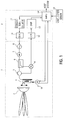
- Fig. 1 is a block diagram showing the configuration of a radar according to an embodiment of the present invention.
- reference numeral 1 denotes an RF block and reference numeral 2 denotes a signal-processing block.
- the RF block 1 transmits and receives radio waves for radar measurement and transmits beat signals of a transmission wave and a reception wave to the signal-processing block 2.
- a modulation counter 11 of the signal-processing block 2 performs counting, so that a DA converter 10 generates a triangular-wave signal, as a result. Then, the modulation counter 11 transmits the value to the DA converter 10.
- the DA converter 10 converts the value to an analog-voltage signal and transmits the analog-voltage signal to a VCO (voltage control oscillator) 8 of the RF block 1, whereby the transmission wave is frequency modulated.
- VCO voltage control oscillator
- an oscillation signal of the VCO 8 is transmitted to a primary radiator 4 via an isolator 7, a coupler 6, and a circulator 5.
- the primary radiator 4 is provided on or near a focal plane of a dielectric lens 3 and the dielectric lens 3 transmits a millimeter-wave signal radiated from the primary radiator 4, as a sharp beam.
- a reflection wave transmitted from an object is made incident on the primary radiator 4 via the dielectric lens 3
- a reception signal is led to a mixer 9 via the circulator 5.
- the reception signal and a local signal that is part of the transmission signal transmitted from the coupler 6 are transmitted to the mixer 9.
- a beat signal corresponding to the signal of the difference between the frequency of the reception signal and that of the local signal is transmitted to an AD converter 12 of the signal-processing block 2, as an intermediate-frequency signal.
- the AD converter 12 converts the intermediate-frequency signal to digital data.
- a DSP (digital-signal processor) 13 performs FFT (fast Fourier transformation) processing for a data string transmitted from the AD converter 12 and calculates a relative distance and a relative speed to the object, which will be described later.
- a portion 16 of the RF block 1 denotes a scan unit for making the primary radiator 4 move parallel to itself on the focal plane of the dielectric lens 3, or a plane parallel to the focal plane.
- a 0-dB coupler is formed between a movable unit where the primary radiator 4 is provided and the fixed-unit side.
- a portion indicated by reference character M denotes the driving motor thereof. The motor allows performing beam scanning in a predetermined area of from negative ten degrees to positive ten degrees in a cycle of 100 ms, for example.
- Reference numeral 14 shown in the signal-processing block 2 denotes a microprocessor for controlling the modulation counter 11 and the scan unit 16.
- the microprocessor 14 determines the counting cycle for the scan unit 16 so that the beam azimuth is directed at a predetermined angle and the VCO 8 is modulated by a triangular wave corresponding to a single crest of an ascending section and a descending section within the standstill time period of the scan unit 6.
- the microprocessor 14 corresponds to a "scanning element" relating to the present invention.
- the microprocessor 14 extracts a pair of a projection portion observed in a frequency spectrum of an ascending-modulation section and a projection portion observed in a frequency spectrum of a descending-modulation section that are obtained by the DSP 13 (pairing).
- a vehicle-speed sensor 15 detects the own-vehicle speed and the microprocessor 14 reads the own-vehicle speed from the vehicle-speed sensor 15 and performs pairing for a pair corresponding to a stationary
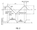
- Fig. 2 shows an example difference between the frequency change of the transmission signal and that of the reception signal caused by the distance and the relative speed to the object.
- An upbeat frequency f BU means the frequency difference between the transmission signal and the reception signal during the frequency of the transmission signal increases.
- a downbeat frequency f BD means the frequency difference between the transmission signal and the reception signal during the frequency of the transmission signal decreases.
- the symbol ⁇ f denotes the frequency-shift width.
- the discrepancy between the transmission signal and the reception signal on the frequency axis corresponds to a Doppler-shift amount generated due to the object's relative speed to the antenna.
- the values of the upbeat f BU and the downbeat f BD change according to the time difference and the Doppler-shift amount. That is to say, the distance between the radar and the object and the object's relative speed to the radar are calculated by detecting the frequency of the upbeat and that of the downbeat.
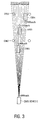
- Fig. 3 shows an example relationship between the azimuths of transmission and reception beams of the radar and a plurality of objects.
- the sign Bo denotes a frontal direction of the vehicle mounted on the own vehicle.
- B + 1, B + 2, and so forth indicate beam azimuths obtained where the beam azimuth is modified from the front to the right.
- B - 1, B - 2, and so forth indicate beam azimuths obtained where the beam azimuth is modified from the front to the left.
- Objects OB2 and OB5 indicated by circles shown in Fig. 3 denote fixed objects on the road side. Further, objects OB1, OB3, and OB4 indicated by squares denote other vehicles ahead of the own vehicle. The traveling directions of the other vehicles are indicated by arrows.
- the relative speed to the road-side objects including the OB2, OB5, and so forth, and stationary objects such as perked vehicles on the road is the same as the own-vehicle speed. Therefore, pairing is performed by using data on the own-vehicle speed obtained by a vehicle-speed sensor, so as to increase the pairing accuracy.
- objects picked up by the radar are stationary objects including a guardrail, a sign, a sound-proof wall, a street light, and so forth, in most cases. Further, in most times, traveling vehicles keep a predetermined distance therebetween except when the road is congested. Therefore, the distance between two vehicles hardly corresponds to the frequency difference (the difference between the upbeat frequency and the downbeat frequency) that is almost the same as that in the case of a stationary object.
- the frequency difference between the projection portions observed in the frequency spectrums of the ascending-modulation section and the descending-modulation section is inversely calculated based on the own-vehicle speed, a pair corresponding to the frequency difference is extracted, and the other projection portions are paired up with one another. Subsequently, the distance and speed of a moving object is calculated.
- Fig. 4 shows example frequency spectrums of beat signals in the ascending-modulation section and the descending-modulation section.
- a solid line indicates the frequency spectrum of the beat signal in the ascending-modulation section and a broken line indicates the frequency spectrum of the beat signal in the descending-modulation section.
- three projection portions are observed in the beat signal in the ascending-modulation section and two projection portions are observed in the beat signal in the descending-modulation section.
- the letter c indicates the speed of light.
- the frequency differences between the two projection portions observed in the frequency spectrum of the beat signal in the ascending-modulation section and the two projection portions generated in the frequency spectrum of the beat signal of the descending-modulation section are 28.3 kHz. Therefore, the projection portions are extracted, as pairs. That is to say, two stationary objects are detected.
- the frequency-shift width ⁇ f is 300 MHz
- the reciprocal of a modulation cycle that is, the modulation frequency fm is 500 Hz
- the letter R indicates a distance
- the letter c indicates the speed of light.
- Fig. 6 shows the above-described example.
- Fig. 6 shows the state of the frequency spectrums of beat signals and two vehicles in the ascending-modulation section and the descending-modulation section.
- Fig. 6(A) shows a spectrum generated by a vehicle at 0 km/h, that is, a stationary vehicle and
- Fig. 6(B) shows a spectrum generated by the two vehicles traveling ahead of the own vehicle at a predetermined distance therefrom at the speed of 100 km/h with a distance of 14.1 m therebetween.
- projection portions generated by two objects are paired with each other in the above-described manner
- projection portions showing the frequency difference of 28.3 kHz corresponding to the stationary object may be paired off with each other and extracted on a priority basis.
- the traveling object may be misidentified as a stationary object, even though a tight turn, a vehicle traveling unsafely, and so forth exist.
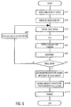
- Fig. 5 is a flowchart showing processing procedures performed by the DSP 13 and the microprocessor 14 shown in Fig. 1.
- data on the own-vehicle speed is read from the vehicle-speed sensor 15 (s1).
- a beam is steered in an initial azimuth under the control of the scan unit 16 (s2).
- the beat-signal digital data converted through the A/D converter 12 is obtained, as many as a predetermined sampling number, and subjected to FFT processing (s3 ⁇ s4).
- the beam azimuth is shifted by as much as a single beam and the same processing is performed (n7 ⁇ s8 ⁇ s3 ⁇ ⁇ ).
- a peak frequency spectrum is obtained for each beam azimuth in the ascending-modulation section and the descending-modulation section over a detection range having a predetermined width extending in the azimuth direction.
- the representative azimuth, representative peak frequency, and representative signal intensity of each group are obtained, as a pair candidate, and a level profile in the azimuth direction is obtained (s9).
- the center azimuth of a predetermined group extending in the beam-azimuth direction and the frequency-axis direction is determined to be the representative azimuth and the center of a predetermined frequency range extending on the frequency axis in the above-described azimuth is determined to be the representative peak frequency, and the signal intensity of the representative peak frequency is determined to be the representative signal intensity.
- the change in the signal intensity in the azimuth direction of the representative frequency of the group is obtained, as a signal-intensity profile.
- the above-described representative values of each group are obtained for each of the ascending-modulation section and the descending-modulation section.
- the coincidence of predetermined pair candidates showing a frequency difference corresponding to a stationary object is weighted, so that the pair candidates are paired up with each other on a priority basis. Subsequently, pairing is performed (s10 ⁇ s11).
- the signal-intensity coincidence is determined to be Ma
- the coincidence of the azimuths is determined to be Md
- the coincidence of the signal-intensity profiles is determined to be Mc.
- the weight of the pair-evaluation value indicating pair characteristics is determined to be m
- the above-described coincidences Ma, Md, and Mc are coefficients of from zero to one and the weight m is a value of at least one.
- the pair-evaluation value E is obtained for each of possible combinations of the representative values of the projection-portion groups extracted, as the pair candidates, and the pair candidates are paired up with one another in order of decreasing values.
- the above-described weight m gives a large value greater than one to a predetermined pair showing the frequency difference corresponding to the stationary object.
- the pair-evaluation value E is obtained by assigning the weight m to the signal-intensity coincidence, the azimuth coincidence, and the signal-intensity-profile coincidence.
- the above-described three coincidences may be modified separately so that the combination showing the frequency difference corresponding to the stationary object is extracted on the priority basis, as a pair.
- Fig. 7 shows an example where the signal-intensity coincidence is modified.
- reference characters A and B denote projection portions observed in the frequency spectrum of the beat signal in the ascending-modulation section and reference characters ⁇ and ⁇ denote projection portions observed in the frequency spectrum of the beat signal in the descending-modulation section.
- the signal-intensity difference between ⁇ and A is 3 dB
- the signal-intensity difference between ⁇ and B is 1 dB.
- the signal-intensity difference is decreased by as much as 3 dB, and the signal-intensity coincidence is obtained.
- Fig. 8 shows an example where the coincidence of the azimuths is modified.
- Fig. 8(A) shows the peak frequency of the projection portion observed in the frequency spectrum of the beat signal in the ascending-modulation section for each of beams of different azimuths and
- Fig. 8(B) shows the peak frequency of the projection portion observed in the frequency spectrum of the beat signal in the descending-modulation section.
- the horizontal axis shows the beam azimuths
- the vertical axis shows the frequencies of the projection portions in the frequency spectrums so that the beam azimuths and the frequencies are expressed by Cartesian coordinates.
- the frequency difference between the representative frequency Fa of the group Gu1 and the representative frequency Fc of the group Gd2 is the frequency difference corresponding to the stationary object, and an azimuth-angle difference between the representative azimuth Bj of the group Gu1 and the representative azimuth Bk of the group Gd2 is within ⁇ 1.0°, the azimuths are considered to be the same as each other. Since the frequency difference between the representative frequency Fa of the group Gu1 and the representative frequency Fb of the group Gd1 does not correspond to the stationary object, the angle difference between the representative azimuths of both the groups is regarded as the difference between the beam azimuth Bj and the beam azimuth Bi.
- Fig. 9 shows example modification of the coincidence of the signal-intensity profiles.
- the representative-frequency difference between the group Gu1 and the group Gd1 is the frequency difference corresponding to the stationary object, the coincidence of both the signal-intensity profiles is modified, so as to be increased.
- the coincidence of the signal-intensity profiles is calculated, as a correlation coefficient, the difference between the correlation-coefficient value and 1.0 is reduced at a predetermined rate (e.g. 1/2) for evaluation.
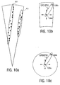
- Fig. 10 shows the locations of objects calculated by using the pairs extracted according to the method shown in the first embodiment. Black circles indicate the locations of objects.
- the objects include a continuous road-side object such as a guardrail, a soundproof wall, a median, the wall of a building, and so forth, a plurality of stationary objects close to one another is detected, as shown in Fig. 10(A).
- the above-described sequence of stationary objects is determined to be a continuous stationary object.
- two continuous stationary objects A1 and A2 are determined.
- Determination whether or not the stationary objects are close to each other is performed by grouping stationary objects detected in a predetermined distance and a predetermined azimuth-angle range. For example, where a stationary object OBb exists within a predetermined distance and a predetermined azimuth-angle range with reference to a predetermined stationary object OBa, as shown in Fig. 10(B), it is determined that the stationary object OBb belongs to the same group that the stationary object OBa belongs to. Next, the same processing is performed for the stationary object OBb and grouping is performed in sequence.
- the above-described processing may be performed on the Cartesian coordinates, as shown in Fig. 10(C). That is to say, stationary objects existing in a predetermined distance range on the Cartesian coordinates may be grouped in sequence.
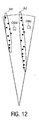
- an area determined to be the continuous stationary object in the above-described manner denotes the guardrail, the soundproof wall, the median, or the wall of the building, for example, a moving object does not exist in the area in normal times.
- the pair is regarded as a pair generated by miss-pairing.
- moving objects that travel at the speed of 30 km/h and the speed of 80 km/h and that falsely exist in an area A1 of the continuous stationary object are regarded as a pair generated by miss-pairing.
- a moving object that falsely exists in an area A2 of the continuous stationary object and that travels at the speed of 20 km/h is regarded as a pair generated by miss-pairing.
- the detection result can be removed, without adversely affecting the probability of detection of an object traveling on the road.
- an object falsely detected beyond the area of the continuous stationary object is often a vehicle traveling on the lane beyond a median (the opposite lane), or a mirror image generated by the soundproof wall, the wall of a tunnel, and so forth, the detection result is removed.
- an object OBd is a vehicle that actually travels ahead of the own vehicle.
- an object OBe is a mirror image of the OBd generated due to the area A2 of the continuous stationary object, or a vehicle reversely traveling on the opposite lane, where the area A2 is the median.
- the detection result relating to the object OBe is removed and not transmitted to a host system.
- the above-described removing processing is not performed for objects beyond a continuous stationary object existing along the traveling direction of the own vehicle.
- the traveling direction of the own vehicle can be detected based on the steering angle of a steering wheel, the yaw rate, and the data obtained by a car navigation system or the like.
- Fig. 13 is a flowchart illustrating procedures performed for the above-described processing. The processing is performed, following the processing procedures described in the first embodiment, as shown in Fig. 5.
- the detection result of the object is removed (s25). After that, data on a new detection result is generated and transmitted to the host system (s26).
- the present invention allows extracting a pair that is a combination of projection portions observed in the frequency spectrums of beat signals in an ascending-modulation section and a descending-modulation section on the priority basis, where the frequency difference between the projection portions corresponds to a stationary object. Therefore, the stationary object can be easily detected and other objects other than the stationary object, such as vehicles traveling ahead, can be detected with increased stability.
- a weight is assigned to the signal-intensity coincidence of the pair showing the frequency difference corresponding to the stationary object. Therefore, the mispairing probability is relatively reduced and a pair generated by the stationary object can be detected with increased stability.
- the beam azimuth of a transmission signal is changed over a predetermined scanning range, the coincidence of azimuths of the first and second projection portions is calculated, a combination showing high coincidence is extracted on the priority basis, as a pair, and a high weight is assigned to the azimuth coincidence of a pair showing the frequency difference corresponding to the stationary object. Subsequently, the mispairing probability is relatively reduced and the pair generated by the stationary object can be detected with increased stability.
- a continuous stationary object is determined based on the continuity of the azimuth direction or distance direction of a pair showing the frequency difference corresponding to the stationary object. Therefore, the areas of continuous stationary objects forming the majority of detected objects can be detected with stability and moving objects such as vehicles traveling relatively ahead can be detected with stability.
- the detection result is not output. Therefore, it becomes possible to output only a significant object of detected objects to the host system, reduce the entire data processing amount, and perform processing based on the detection result with high speed.
- the radar of the present invention can easily detect a stationary object and search for an object other than the stationary object, such as a vehicle traveling ahead, with increased stability.
Landscapes
- Engineering & Computer Science (AREA)
- Radar, Positioning & Navigation (AREA)
- Remote Sensing (AREA)
- Computer Networks & Wireless Communication (AREA)
- Physics & Mathematics (AREA)
- General Physics & Mathematics (AREA)
- Signal Processing (AREA)
- Radar Systems Or Details Thereof (AREA)
Abstract
Description
a frequency-analysis element for obtaining data on the frequency spectrum of a beat signal indicating the frequency difference between the transmission signal and the reception signal,
a pair-extraction element for extracting a pair of first and second projection portions caused by one and the same object, where the first projection portion is observed in the frequency spectrum of a beat signal of the ascending-modulation section and the second projection portion is observed in the frequency spectrum of a beat signal of the descending-modulation section, and
a predetermined element for detecting at least one of the relative distance and relative speed of the object based on frequencies of the two projection portions forming the pair.
the pair-extraction element inversely calculates the frequency difference between the projection portions observed in the frequency spectrums of the beat signals in the ascending-modulation section and the descending-modulation section based on the moving-speed data, where the frequency difference corresponds to a stationary object, and extracts a pair corresponding to the frequency difference on a priority basis.


According to the above-described relationship, the peak-frequency distance between the projection portions generated by reflection waves of the two vehicles substantially matches with the frequency difference caused by the stationary objects.
Claims (15)
- A radar including a transmission-and-reception element for transmitting a transmission signal including an ascending-modulation section where a frequency gradually increases and a descending-modulation section where the frequency gradually decreases in an alternating manner and receiving a reception signal including a reflection signal transmitted from an object, a frequency-analysis element for obtaining data on the frequency spectrum of a beat signal indicating the frequency difference between the transmission signal and the reception signal, a pair-extraction element for extracting a pair of first and second projection portions caused by one and the same object, where the first projection portion is observed in the frequency spectrum of a beat signal of the ascending-modulation section and the second projection portion is observed in the frequency spectrum of a beat signal of the descending-modulation section, and a predetermined element for detecting at least one of the relative distance and relative speed of the object based on frequencies of the two projection portions forming the pair, wherein a predetermined element for inputting data on the moving speed of a moving object having the radar mounted thereon is provided, and the pair-extraction element inversely calculates the frequency difference between the projection portions observed in the frequency spectrums of the beat signals in the ascending-modulation section and the descending-modulation section based on the moving-speed data, where the frequency difference corresponds to a stationary object, and extracts a pair corresponding to the frequency difference on a priority basis.
- The radar according to Claim 1, wherein the pair-extraction element calculates the coincidence of the signal intensity of the first projection portion and the signal intensity of the second projection portion, extracts a combination showing high coincidence on a priority basis, as a pair, and assigns a high weight to the signal-intensity coincidence of a pair corresponding to the frequency difference.
- The radar according to Claim 1, comprising a scanning element for changing the beam azimuth of the transmission signal over a predetermined scanning range, wherein the pair-extraction element calculates the coincidence of azimuths of the first and second projection portions, extracts a combination showing high coincidence on a priority basis, as a pair, and assigns a high weight to the azimuth coincidence of a pair corresponding to the frequency difference.
- The radar according to Claim 2, comprising a scanning element for changing the beam azimuth of the transmission signal over a predetermined scanning range, wherein the pair-extraction element calculates the coincidence of azimuths of the first and second projection portions, extracts a combination showing high coincidence on a priority basis, as a pair, and assigns a high weight to the azimuth coincidence of a pair corresponding to the frequency difference.
- The radar according to Claim 1, comprising a scanning element for changing the beam azimuth of the transmission signal over a predetermined scanning range, wherein the pair-extraction element calculates the degree of correlation between signal-intensity profiles in the azimuth direction of the first and second projection portions, extracts a combination showing a high correlation degree on a priority basis, as a pair, and assigns a high weight to the correlation degree of a pair showing the frequency difference.
- The radar according to Claim 2, comprising a scanning element for changing the beam azimuth of the transmission signal over a predetermined scanning range, wherein the pair-extraction element calculates the degree of correlation between signal-intensity profiles in the azimuth direction of the first and second projection portions, extracts a combination showing a high correlation degree on a priority basis, as a pair, and assigns a high weight to the correlation degree of a pair showing the frequency difference.
- The radar according to Claim 3, comprising a scanning element for changing the beam azimuth of the transmission signal over a predetermined scanning range, wherein the pair-extraction element calculates the degree of correlation between signal-intensity profiles in the azimuth direction of the first and second projection portions, extracts a combination showing a high correlation degree on a priority basis, as a pair, and assigns a high weight to the correlation degree of a pair showing the frequency difference.
- The radar according to Claim 4, comprising a scanning element for changing the beam azimuth of the transmission signal over a predetermined scanning range, wherein the pair-extraction element calculates the degree of correlation between signal-intensity profiles in the azimuth direction of the first and second projection portions, extracts a combination showing a high correlation degree on a priority basis, as a pair, and assigns a high weight to the correlation degree of a pair showing the frequency difference.
- The radar according to Claims 1 to 8, comprising a predetermined element, wherein where a predetermined number of the pairs showing the frequency difference exist along at least one of the azimuth direction and the distance direction, the element determines that the pairs indicate a continuous stationary object.
- The radar according to Claims 1 to 8, comprising a predetermined element, wherein where an object corresponding to a pair that does not correspond to the frequency difference is detected in a predetermined area where the continuous stationary object exists, the element determines that the pair extraction is an error.
- The radar according to Claim 9, comprising a predetermined element, wherein where an object corresponding to a pair that does not correspond to the frequency difference is detected in a predetermined area where the continuous stationary object exists, the element determines that the pair extraction is an error.
- The radar according to Claims 1 to 8, comprising a predetermined element, wherein where a predetermined object is detected beyond the continuous stationary object, the element does not output the detection result.
- The radar according to Claim 9, comprising a predetermined element, wherein where a predetermined object is detected beyond the continuous stationary object, the element does not output the detection result.
- The radar according to Claim 10, comprising a predetermined element, wherein where a predetermined object is detected beyond the continuous stationary object, the element does not output the detection result.
- The radar according to Claim 11, comprising a predetermined element, wherein where a predetermined object is detected beyond the continuous stationary object, the element does not output the detection result.
Applications Claiming Priority (3)
| Application Number | Priority Date | Filing Date | Title |
|---|---|---|---|
| JP2002163349A JP3797277B2 (en) | 2002-06-04 | 2002-06-04 | Radar |
| JP2002163349 | 2002-06-04 | ||
| PCT/JP2003/006373 WO2003102623A1 (en) | 2002-06-04 | 2003-05-22 | Radar |
Publications (3)
| Publication Number | Publication Date |
|---|---|
| EP1510833A1 true EP1510833A1 (en) | 2005-03-02 |
| EP1510833A4 EP1510833A4 (en) | 2011-03-02 |
| EP1510833B1 EP1510833B1 (en) | 2013-05-08 |
Family
ID=29706631
Family Applications (1)
| Application Number | Title | Priority Date | Filing Date |
|---|---|---|---|
| EP03730562.0A Expired - Lifetime EP1510833B1 (en) | 2002-06-04 | 2003-05-22 | Radar |
Country Status (5)
| Country | Link |
|---|---|
| US (1) | US7034743B2 (en) |
| EP (1) | EP1510833B1 (en) |
| JP (1) | JP3797277B2 (en) |
| AU (1) | AU2003242381A1 (en) |
| WO (1) | WO2003102623A1 (en) |
Families Citing this family (41)
| Publication number | Priority date | Publication date | Assignee | Title |
|---|---|---|---|---|
| JP3991793B2 (en) * | 2002-07-05 | 2007-10-17 | 株式会社村田製作所 | Radar |
| JP3954951B2 (en) * | 2002-10-17 | 2007-08-08 | 本田技研工業株式会社 | Vehicle object detection device |
| JP3954993B2 (en) * | 2003-07-07 | 2007-08-08 | 本田技研工業株式会社 | Vehicle object detection device |
| JP2004226158A (en) * | 2003-01-21 | 2004-08-12 | Fujitsu Ten Ltd | Fm-cw radar device |
| JP2005049281A (en) * | 2003-07-30 | 2005-02-24 | Denso Corp | Object recognition apparatus and object recognition method |
| US7312745B2 (en) * | 2004-01-07 | 2007-12-25 | Murata Manufacturing Co., Ltd | Radar |
| JPWO2006013689A1 (en) * | 2004-08-06 | 2008-05-01 | 株式会社村田製作所 | Radar |
| JP4541101B2 (en) * | 2004-10-21 | 2010-09-08 | アルパイン株式会社 | Other vehicle detector and other vehicle detection method |
| JP4529733B2 (en) * | 2005-03-02 | 2010-08-25 | 株式会社デンソー | In-vehicle radar system |
| JP4613711B2 (en) * | 2005-06-27 | 2011-01-19 | 日産自動車株式会社 | Object detection apparatus and object detection method |
| JP4956778B2 (en) * | 2005-12-01 | 2012-06-20 | 日産自動車株式会社 | Object detection apparatus and object detection method |
| JP4684876B2 (en) * | 2005-12-14 | 2011-05-18 | 富士通テン株式会社 | Radar device and method for detecting object of radar device |
| JP4793094B2 (en) * | 2006-05-17 | 2011-10-12 | 株式会社デンソー | Driving environment recognition device |
| JP2009014631A (en) * | 2007-07-09 | 2009-01-22 | Fujitsu Ten Ltd | Radar device and method for detecting target thereof |
| JP4385065B2 (en) * | 2007-09-06 | 2009-12-16 | 本田技研工業株式会社 | Vehicle object detection device |
| US7733266B2 (en) | 2007-09-06 | 2010-06-08 | Honda Motor Co., Ltd. | Control target recognition system and vehicle object detection system |
| US7612707B2 (en) * | 2007-09-28 | 2009-11-03 | Banner Engineering Corporation | Configurable radar sensor |
| JP5061879B2 (en) * | 2007-12-17 | 2012-10-31 | 富士通株式会社 | FMCW radar equipment |
| JP2009271008A (en) * | 2008-05-09 | 2009-11-19 | Honda Motor Co Ltd | Object sensor |
| JP2010002265A (en) * | 2008-06-19 | 2010-01-07 | Fujitsu Ltd | Radar equipment, measurement method and measurement program |
| JP5317570B2 (en) * | 2008-08-07 | 2013-10-16 | 富士通テン株式会社 | Radar apparatus and target detection method |
| US8154437B2 (en) * | 2008-12-05 | 2012-04-10 | Toyota Jidosha Kabushiki Kaisha | Traveling direction vector reliability determination method and traveling direction vector reliability determination device |
| DE112008004069B4 (en) * | 2008-12-18 | 2014-09-04 | Toyota Jidosha Kabushiki Kaisha | radar system |
| JP2011069710A (en) | 2009-09-25 | 2011-04-07 | Fujitsu Ten Ltd | Signal processor, radar apparatus, object detection system, signal processing method, and program |
| JP5018943B2 (en) | 2010-09-07 | 2012-09-05 | 株式会社デンソー | Radar equipment |
| JP5709476B2 (en) * | 2010-11-10 | 2015-04-30 | 富士通テン株式会社 | Radar equipment |
| US9024809B2 (en) * | 2011-03-17 | 2015-05-05 | Sony Corporation | Object detection system and method |
| JP2012242166A (en) * | 2011-05-17 | 2012-12-10 | Fujitsu Ten Ltd | Radar device |
| JP6280319B2 (en) * | 2012-10-30 | 2018-02-14 | 株式会社デンソーテン | Radar apparatus and signal processing method |
| JP6200644B2 (en) * | 2012-12-07 | 2017-09-20 | 富士通テン株式会社 | Radar apparatus and signal processing method |
| KR101826544B1 (en) | 2012-12-27 | 2018-02-07 | 현대자동차 주식회사 | Method for controlling vehicle during passing through the tunnel and system hereof |
| JP5972402B2 (en) * | 2013-02-01 | 2016-08-17 | 三菱電機株式会社 | Radar equipment |
| JP6127554B2 (en) * | 2013-02-08 | 2017-05-17 | 株式会社デンソー | Radar equipment |
| US10222462B2 (en) * | 2013-02-27 | 2019-03-05 | Waymo Llc | Adaptive algorithms for interrogating the viewable scene of an automotive radar |
| JP6294594B2 (en) | 2013-04-19 | 2018-03-14 | 株式会社デンソーテン | Radar apparatus and signal processing method |
| KR101892306B1 (en) * | 2013-12-18 | 2018-08-27 | 주식회사 만도 | Method and apparatus for detecting road environment based on frequency modulated continuous wave radar |
| JP2015155807A (en) * | 2014-02-20 | 2015-08-27 | 富士通テン株式会社 | Radar device, vehicle control system, and signal processing method |
| JP2016070772A (en) * | 2014-09-30 | 2016-05-09 | 富士通テン株式会社 | Rader system, vehicle control system, and signal processing method |
| CN107153189B (en) * | 2017-04-18 | 2021-08-03 | 上海交通大学 | Signal Processing Method for Chirp Continuous Wave Radar Ranging |
| KR102739239B1 (en) * | 2019-03-27 | 2024-12-05 | 주식회사 에이치엘클레무브 | Apparatus and method for controlling vehicle |
| DE102020127643A1 (en) * | 2020-10-21 | 2022-04-21 | Valeo Schalter Und Sensoren Gmbh | ULTRASONIC TRANSCEIVER AND METHOD OF MANUFACTURE THEREOF |
Family Cites Families (20)
| Publication number | Priority date | Publication date | Assignee | Title |
|---|---|---|---|---|
| JP2765773B2 (en) * | 1991-11-26 | 1998-06-18 | 富士通テン株式会社 | Millimeter wave radar distance / velocity measurement system |
| JP3102224B2 (en) * | 1993-09-28 | 2000-10-23 | トヨタ自動車株式会社 | In-vehicle radar device |
| GB2283631B (en) * | 1993-11-06 | 1998-04-29 | Roke Manor Research | Radar apparatus |
| JP3550829B2 (en) * | 1995-01-24 | 2004-08-04 | 株式会社デンソー | FM-CW radar device |
| JP3104599B2 (en) | 1995-11-24 | 2000-10-30 | トヨタ自動車株式会社 | FM-CW radar device |
| JP3305624B2 (en) * | 1997-07-16 | 2002-07-24 | 本田技研工業株式会社 | Object detection device |
| JP2930236B1 (en) * | 1998-01-26 | 1999-08-03 | 本田技研工業株式会社 | Radar equipment |
| JPH11271430A (en) * | 1998-03-25 | 1999-10-08 | Toyota Central Res & Dev Lab Inc | Automotive radar equipment |
| JPH11271433A (en) * | 1998-03-26 | 1999-10-08 | Toyota Central Res & Dev Lab Inc | Radar equipment |
| JP3480486B2 (en) * | 1998-08-18 | 2003-12-22 | トヨタ自動車株式会社 | FM-CW radar device |
| DE19942665B4 (en) | 1998-09-07 | 2014-02-13 | Denso Corporation | FM CW radar apparatus for measuring the distance to a target and the relative velocity of the target |
| JP3371854B2 (en) | 1998-09-07 | 2003-01-27 | 株式会社デンソー | Ambient situation detection device and recording medium |
| JP3512066B2 (en) * | 1998-12-10 | 2004-03-29 | トヨタ自動車株式会社 | Automotive radar equipment |
| JP4045043B2 (en) * | 1999-02-24 | 2008-02-13 | 本田技研工業株式会社 | Radar equipment |
| JP3489514B2 (en) * | 1999-12-09 | 2004-01-19 | 株式会社デンソー | FMCW radar equipment |
| JP2002236170A (en) * | 2001-02-06 | 2002-08-23 | Fujitsu Ten Ltd | Fm-cw radar processing device |
| JP3788322B2 (en) * | 2001-05-30 | 2006-06-21 | 株式会社村田製作所 | Radar |
| JP3729127B2 (en) * | 2001-12-13 | 2005-12-21 | 株式会社村田製作所 | Radar |
| JP3753071B2 (en) * | 2002-01-07 | 2006-03-08 | 株式会社村田製作所 | Radar |
| US6906661B2 (en) * | 2002-10-17 | 2005-06-14 | Honda Motor Co., Ltd. | Object-detecting system for vehicle |
-
2002
- 2002-06-04 JP JP2002163349A patent/JP3797277B2/en not_active Expired - Fee Related
-
2003
- 2003-05-22 EP EP03730562.0A patent/EP1510833B1/en not_active Expired - Lifetime
- 2003-05-22 AU AU2003242381A patent/AU2003242381A1/en not_active Abandoned
- 2003-05-22 US US10/516,924 patent/US7034743B2/en not_active Expired - Fee Related
- 2003-05-22 WO PCT/JP2003/006373 patent/WO2003102623A1/en not_active Ceased
Also Published As
| Publication number | Publication date |
|---|---|
| EP1510833A4 (en) | 2011-03-02 |
| WO2003102623A1 (en) | 2003-12-11 |
| EP1510833B1 (en) | 2013-05-08 |
| US20050174282A1 (en) | 2005-08-11 |
| US7034743B2 (en) | 2006-04-25 |
| JP2004012198A (en) | 2004-01-15 |
| AU2003242381A1 (en) | 2003-12-19 |
| JP3797277B2 (en) | 2006-07-12 |
Similar Documents
| Publication | Publication Date | Title |
|---|---|---|
| EP1510833B1 (en) | Radar | |
| KR100662063B1 (en) | Still Object Detection Method of Scanned Radar | |
| JP4093109B2 (en) | Radar equipment for vehicles | |
| US6693583B2 (en) | Object recognition apparatus and method thereof | |
| US6900754B2 (en) | Signal processing method for use with scanning radar | |
| JP3750102B2 (en) | In-vehicle radar system | |
| JP3385304B2 (en) | Automotive radar equipment | |
| US20100271257A1 (en) | Radar apparatus | |
| JP2004163340A (en) | Automotive radar equipment | |
| JPWO2007111130A1 (en) | Radar device and moving body | |
| JP2001166044A (en) | Method of detecting moving object and / or fixed object in vehicle course transition | |
| WO2021187455A1 (en) | Radar system | |
| JP3744860B2 (en) | Scanning radar signal processing method | |
| JP4079739B2 (en) | Automotive radar equipment | |
| JPH1138121A (en) | Automotive radar equipment | |
| JP4064693B2 (en) | Scanning FM-CW radar signal processing method | |
| US6906661B2 (en) | Object-detecting system for vehicle | |
| JP3635228B2 (en) | Scanning radar signal processing method | |
| JP2000147102A (en) | FMCW radar device and recording medium | |
| JP3565713B2 (en) | Signal processing device for FM-CW scan radar | |
| JPH06207979A (en) | Frequency modulation radar device | |
| JP2000099875A (en) | Vehicle detector | |
| JP3230362B2 (en) | Obstacle detection device | |
| JP2008014956A (en) | Radar equipment for vehicles | |
| JP2000111644A (en) | Vehicle detection device |
Legal Events
| Date | Code | Title | Description |
|---|---|---|---|
| PUAI | Public reference made under article 153(3) epc to a published international application that has entered the european phase |
Free format text: ORIGINAL CODE: 0009012 |
|
| 17P | Request for examination filed |
Effective date: 20041129 |
|
| AK | Designated contracting states |
Kind code of ref document: A1 Designated state(s): AT BE BG CH CY CZ DE DK EE ES FI FR GB GR HU IE IT LI LU MC NL PT RO SE SI SK TR |
|
| AX | Request for extension of the european patent |
Extension state: AL LT LV MK |
|
| RAP1 | Party data changed (applicant data changed or rights of an application transferred) |
Owner name: MURATA MANUFACTURING CO., LTD. |
|
| RIN1 | Information on inventor provided before grant (corrected) |
Inventor name: ISHII, TORUC/O MURATA MANUFACTURING CO., LTD. Inventor name: NISHIMURA, TETSUC/O MURATA MANUFACTURING CO.,LTD. Inventor name: NAKANISHI, MOTOIC/O MURATA MANUFACTURING CO.,LTD. |
|
| DAX | Request for extension of the european patent (deleted) | ||
| A4 | Supplementary search report drawn up and despatched |
Effective date: 20110202 |
|
| RIC1 | Information provided on ipc code assigned before grant |
Ipc: G01S 13/34 20060101AFI20031217BHEP Ipc: G01S 13/93 20060101ALI20110127BHEP Ipc: G01S 7/35 20060101ALI20110127BHEP |
|
| 17Q | First examination report despatched |
Effective date: 20111018 |
|
| GRAP | Despatch of communication of intention to grant a patent |
Free format text: ORIGINAL CODE: EPIDOSNIGR1 |
|
| GRAS | Grant fee paid |
Free format text: ORIGINAL CODE: EPIDOSNIGR3 |
|
| GRAA | (expected) grant |
Free format text: ORIGINAL CODE: 0009210 |
|
| AK | Designated contracting states |
Kind code of ref document: B1 Designated state(s): AT BE BG CH CY CZ DE DK EE ES FI FR GB GR HU IE IT LI LU MC NL PT RO SE SI SK TR |
|
| REG | Reference to a national code |
Ref country code: GB Ref legal event code: FG4D |
|
| REG | Reference to a national code |
Ref country code: CH Ref legal event code: EP Ref country code: AT Ref legal event code: REF Ref document number: 611325 Country of ref document: AT Kind code of ref document: T Effective date: 20130515 |
|
| REG | Reference to a national code |
Ref country code: IE Ref legal event code: FG4D |
|
| REG | Reference to a national code |
Ref country code: DE Ref legal event code: R096 Ref document number: 60343995 Country of ref document: DE Effective date: 20130704 |
|
| PGFP | Annual fee paid to national office [announced via postgrant information from national office to epo] |
Ref country code: DE Payment date: 20130418 Year of fee payment: 11 |
|
| REG | Reference to a national code |
Ref country code: AT Ref legal event code: MK05 Ref document number: 611325 Country of ref document: AT Kind code of ref document: T Effective date: 20130508 |
|
| REG | Reference to a national code |
Ref country code: NL Ref legal event code: VDEP Effective date: 20130508 |
|
| PG25 | Lapsed in a contracting state [announced via postgrant information from national office to epo] |
Ref country code: PT Free format text: LAPSE BECAUSE OF FAILURE TO SUBMIT A TRANSLATION OF THE DESCRIPTION OR TO PAY THE FEE WITHIN THE PRESCRIBED TIME-LIMIT Effective date: 20130909 Ref country code: ES Free format text: LAPSE BECAUSE OF FAILURE TO SUBMIT A TRANSLATION OF THE DESCRIPTION OR TO PAY THE FEE WITHIN THE PRESCRIBED TIME-LIMIT Effective date: 20130819 Ref country code: AT Free format text: LAPSE BECAUSE OF FAILURE TO SUBMIT A TRANSLATION OF THE DESCRIPTION OR TO PAY THE FEE WITHIN THE PRESCRIBED TIME-LIMIT Effective date: 20130508 Ref country code: SE Free format text: LAPSE BECAUSE OF FAILURE TO SUBMIT A TRANSLATION OF THE DESCRIPTION OR TO PAY THE FEE WITHIN THE PRESCRIBED TIME-LIMIT Effective date: 20130508 Ref country code: SI Free format text: LAPSE BECAUSE OF FAILURE TO SUBMIT A TRANSLATION OF THE DESCRIPTION OR TO PAY THE FEE WITHIN THE PRESCRIBED TIME-LIMIT Effective date: 20130508 Ref country code: FI Free format text: LAPSE BECAUSE OF FAILURE TO SUBMIT A TRANSLATION OF THE DESCRIPTION OR TO PAY THE FEE WITHIN THE PRESCRIBED TIME-LIMIT Effective date: 20130508 Ref country code: GR Free format text: LAPSE BECAUSE OF FAILURE TO SUBMIT A TRANSLATION OF THE DESCRIPTION OR TO PAY THE FEE WITHIN THE PRESCRIBED TIME-LIMIT Effective date: 20130809 |
|
| PG25 | Lapsed in a contracting state [announced via postgrant information from national office to epo] |
Ref country code: CY Free format text: LAPSE BECAUSE OF FAILURE TO SUBMIT A TRANSLATION OF THE DESCRIPTION OR TO PAY THE FEE WITHIN THE PRESCRIBED TIME-LIMIT Effective date: 20130508 Ref country code: BG Free format text: LAPSE BECAUSE OF FAILURE TO SUBMIT A TRANSLATION OF THE DESCRIPTION OR TO PAY THE FEE WITHIN THE PRESCRIBED TIME-LIMIT Effective date: 20130808 |
|
| REG | Reference to a national code |
Ref country code: CH Ref legal event code: PL |
|
| PG25 | Lapsed in a contracting state [announced via postgrant information from national office to epo] |
Ref country code: SK Free format text: LAPSE BECAUSE OF FAILURE TO SUBMIT A TRANSLATION OF THE DESCRIPTION OR TO PAY THE FEE WITHIN THE PRESCRIBED TIME-LIMIT Effective date: 20130508 Ref country code: BE Free format text: LAPSE BECAUSE OF FAILURE TO SUBMIT A TRANSLATION OF THE DESCRIPTION OR TO PAY THE FEE WITHIN THE PRESCRIBED TIME-LIMIT Effective date: 20130508 Ref country code: EE Free format text: LAPSE BECAUSE OF FAILURE TO SUBMIT A TRANSLATION OF THE DESCRIPTION OR TO PAY THE FEE WITHIN THE PRESCRIBED TIME-LIMIT Effective date: 20130508 Ref country code: LI Free format text: LAPSE BECAUSE OF NON-PAYMENT OF DUE FEES Effective date: 20130531 Ref country code: CZ Free format text: LAPSE BECAUSE OF FAILURE TO SUBMIT A TRANSLATION OF THE DESCRIPTION OR TO PAY THE FEE WITHIN THE PRESCRIBED TIME-LIMIT Effective date: 20130508 Ref country code: DK Free format text: LAPSE BECAUSE OF FAILURE TO SUBMIT A TRANSLATION OF THE DESCRIPTION OR TO PAY THE FEE WITHIN THE PRESCRIBED TIME-LIMIT Effective date: 20130508 Ref country code: CH Free format text: LAPSE BECAUSE OF NON-PAYMENT OF DUE FEES Effective date: 20130531 |
|
| REG | Reference to a national code |
Ref country code: IE Ref legal event code: MM4A |
|
| PG25 | Lapsed in a contracting state [announced via postgrant information from national office to epo] |
Ref country code: IT Free format text: LAPSE BECAUSE OF FAILURE TO SUBMIT A TRANSLATION OF THE DESCRIPTION OR TO PAY THE FEE WITHIN THE PRESCRIBED TIME-LIMIT Effective date: 20130508 Ref country code: RO Free format text: LAPSE BECAUSE OF FAILURE TO SUBMIT A TRANSLATION OF THE DESCRIPTION OR TO PAY THE FEE WITHIN THE PRESCRIBED TIME-LIMIT Effective date: 20130508 Ref country code: MC Free format text: LAPSE BECAUSE OF FAILURE TO SUBMIT A TRANSLATION OF THE DESCRIPTION OR TO PAY THE FEE WITHIN THE PRESCRIBED TIME-LIMIT Effective date: 20130508 Ref country code: NL Free format text: LAPSE BECAUSE OF FAILURE TO SUBMIT A TRANSLATION OF THE DESCRIPTION OR TO PAY THE FEE WITHIN THE PRESCRIBED TIME-LIMIT Effective date: 20130508 |
|
| PLBE | No opposition filed within time limit |
Free format text: ORIGINAL CODE: 0009261 |
|
| STAA | Information on the status of an ep patent application or granted ep patent |
Free format text: STATUS: NO OPPOSITION FILED WITHIN TIME LIMIT |
|
| REG | Reference to a national code |
Ref country code: FR Ref legal event code: ST Effective date: 20140228 |
|
| 26N | No opposition filed |
Effective date: 20140211 |
|
| GBPC | Gb: european patent ceased through non-payment of renewal fee |
Effective date: 20130808 |
|
| PG25 | Lapsed in a contracting state [announced via postgrant information from national office to epo] |
Ref country code: IE Free format text: LAPSE BECAUSE OF NON-PAYMENT OF DUE FEES Effective date: 20130522 |
|
| REG | Reference to a national code |
Ref country code: DE Ref legal event code: R097 Ref document number: 60343995 Country of ref document: DE Effective date: 20140211 |
|
| PG25 | Lapsed in a contracting state [announced via postgrant information from national office to epo] |
Ref country code: FR Free format text: LAPSE BECAUSE OF NON-PAYMENT OF DUE FEES Effective date: 20130708 |
|
| PG25 | Lapsed in a contracting state [announced via postgrant information from national office to epo] |
Ref country code: GB Free format text: LAPSE BECAUSE OF NON-PAYMENT OF DUE FEES Effective date: 20130808 |
|
| REG | Reference to a national code |
Ref country code: DE Ref legal event code: R119 Ref document number: 60343995 Country of ref document: DE |
|
| REG | Reference to a national code |
Ref country code: DE Ref legal event code: R119 Ref document number: 60343995 Country of ref document: DE Effective date: 20141202 |
|
| PG25 | Lapsed in a contracting state [announced via postgrant information from national office to epo] |
Ref country code: DE Free format text: LAPSE BECAUSE OF NON-PAYMENT OF DUE FEES Effective date: 20141202 |
|
| PG25 | Lapsed in a contracting state [announced via postgrant information from national office to epo] |
Ref country code: TR Free format text: LAPSE BECAUSE OF FAILURE TO SUBMIT A TRANSLATION OF THE DESCRIPTION OR TO PAY THE FEE WITHIN THE PRESCRIBED TIME-LIMIT Effective date: 20130508 |
|
| PG25 | Lapsed in a contracting state [announced via postgrant information from national office to epo] |
Ref country code: HU Free format text: LAPSE BECAUSE OF FAILURE TO SUBMIT A TRANSLATION OF THE DESCRIPTION OR TO PAY THE FEE WITHIN THE PRESCRIBED TIME-LIMIT; INVALID AB INITIO Effective date: 20030522 Ref country code: LU Free format text: LAPSE BECAUSE OF NON-PAYMENT OF DUE FEES Effective date: 20130522 |