EP1510788A2 - Potentiometervorrichtung zur Erfassung von Ventilpositionen - Google Patents
Potentiometervorrichtung zur Erfassung von Ventilpositionen Download PDFInfo
- Publication number
- EP1510788A2 EP1510788A2 EP04016193A EP04016193A EP1510788A2 EP 1510788 A2 EP1510788 A2 EP 1510788A2 EP 04016193 A EP04016193 A EP 04016193A EP 04016193 A EP04016193 A EP 04016193A EP 1510788 A2 EP1510788 A2 EP 1510788A2
- Authority
- EP
- European Patent Office
- Prior art keywords
- resistor
- control unit
- pull
- voltage signal
- output
- Prior art date
- Legal status (The legal status is an assumption and is not a legal conclusion. Google has not performed a legal analysis and makes no representation as to the accuracy of the status listed.)
- Withdrawn
Links
Images

Classifications
-
- G—PHYSICS
- G01—MEASURING; TESTING
- G01D—MEASURING NOT SPECIALLY ADAPTED FOR A SPECIFIC VARIABLE; ARRANGEMENTS FOR MEASURING TWO OR MORE VARIABLES NOT COVERED IN A SINGLE OTHER SUBCLASS; TARIFF METERING APPARATUS; MEASURING OR TESTING NOT OTHERWISE PROVIDED FOR
- G01D3/00—Indicating or recording apparatus with provision for the special purposes referred to in the subgroups
- G01D3/08—Indicating or recording apparatus with provision for the special purposes referred to in the subgroups with provision for safeguarding the apparatus, e.g. against abnormal operation, against breakdown
-
- F—MECHANICAL ENGINEERING; LIGHTING; HEATING; WEAPONS; BLASTING
- F16—ENGINEERING ELEMENTS AND UNITS; GENERAL MEASURES FOR PRODUCING AND MAINTAINING EFFECTIVE FUNCTIONING OF MACHINES OR INSTALLATIONS; THERMAL INSULATION IN GENERAL
- F16K—VALVES; TAPS; COCKS; ACTUATING-FLOATS; DEVICES FOR VENTING OR AERATING
- F16K37/00—Special means in or on valves or other cut-off apparatus for indicating or recording operation thereof, or for enabling an alarm to be given
- F16K37/0025—Electrical or magnetic means
- F16K37/0041—Electrical or magnetic means for measuring valve parameters
-
- G—PHYSICS
- G01—MEASURING; TESTING
- G01D—MEASURING NOT SPECIALLY ADAPTED FOR A SPECIFIC VARIABLE; ARRANGEMENTS FOR MEASURING TWO OR MORE VARIABLES NOT COVERED IN A SINGLE OTHER SUBCLASS; TARIFF METERING APPARATUS; MEASURING OR TESTING NOT OTHERWISE PROVIDED FOR
- G01D5/00—Mechanical means for transferring the output of a sensing member; Means for converting the output of a sensing member to another variable where the form or nature of the sensing member does not constrain the means for converting; Transducers not specially adapted for a specific variable
- G01D5/12—Mechanical means for transferring the output of a sensing member; Means for converting the output of a sensing member to another variable where the form or nature of the sensing member does not constrain the means for converting; Transducers not specially adapted for a specific variable using electric or magnetic means
- G01D5/14—Mechanical means for transferring the output of a sensing member; Means for converting the output of a sensing member to another variable where the form or nature of the sensing member does not constrain the means for converting; Transducers not specially adapted for a specific variable using electric or magnetic means influencing the magnitude of a current or voltage
- G01D5/16—Mechanical means for transferring the output of a sensing member; Means for converting the output of a sensing member to another variable where the form or nature of the sensing member does not constrain the means for converting; Transducers not specially adapted for a specific variable using electric or magnetic means influencing the magnitude of a current or voltage by varying resistance
- G01D5/165—Mechanical means for transferring the output of a sensing member; Means for converting the output of a sensing member to another variable where the form or nature of the sensing member does not constrain the means for converting; Transducers not specially adapted for a specific variable using electric or magnetic means influencing the magnitude of a current or voltage by varying resistance by relative movement of a point of contact or actuation and a resistive track
Definitions
- the invention relates to a potentiometer device for detecting valve positions, wherein a voltage signal U s is transferable to a control unit having an A / D converter, is arranged with a support member on the at least one slider track with a contact therewith slider member, wherein the Gripper path between a supply voltage U v of the control unit and ground is connected and the wiper element is connected to a protective resistor via an output to the control unit, wherein the control unit has a resistor for detecting a cable drop, which is a pull-down resistor between voltage signal U s and ground, or as a pull-up resistor between supply voltage U v and voltage signal U s is executed.
- potentiometer devices are well known and used for position detection e.g. used in throttle valves, exhaust gas recirculation valves, etc.
- a pull-down resistor or to provide a pull-up resistor such that the voltage signal at the A / D converter as error signal, d. H. either as implausibly low Potential or as an implausible high signal, is present.
- Such a potentiometer device has the disadvantage that even at high so-called noise resistance between the slider track and wiper element, for example by Contamination or friction polymers can be generated, an error signal generated becomes.
- the invention is therefore based on the object, a potentiometer to which easily cause a faulty output signal due to Noise resistance in offset operation is prevented.
- This object is achieved in that a resistor is provided at the output, in the first case between supply voltage U v the voltage signal U s as a pull-up resistor and in the second case between the voltage signal U s and ground as a pull-down Resistance exists.
- the ratio between the Resistance and resistance in the first case in the range of 3: 1 to 8: 1 and in the second case is in the range of 1: 8 to 1: 3.
- resistor directly on the support element.
- the plug element can also be plugged onto an input of the potentiometer device for transmitting the supply voltage U v .
- Figure 1 shows schematically the exhaust gas recirculation in an Otto internal combustion engine.
- the exhaust gas discharged from an internal combustion engine 1 can be exhausted via an exhaust gas recirculation valve 2 supplied to the air flow downstream of a throttle valve 3 become.
- 4 denotes a control unit for the exhaust gas recirculation valve 2, in addition to other engine characteristics and a bearing feedback 5 of a not shown Potentiometer 6 receives to the exhaust gas recirculation via the exhaust gas recirculation valve 2 to regulate.
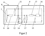
- FIG. 2 shows a block diagram of a potentiometer device 6 according to the invention.
- FIG. 2 shows a part of the wiring of the control device 4.
- at least one slider track 7 is connected on a carrier element 8 between a supply voltage U v of the control unit 4 and ground.
- the potentiometer device has a pull-up resistor 11, which is connected between the supply voltage U v and the voltage signal U s .
- the voltage signal U s is passed in a known manner via an output 12 to the control unit 4, wherein the signal is first smoothed in a known manner by a resistor 13 and capacitors 14, 15, before an A / D converter 16 digitizes the signal.
- a pull-down resistor 14 is provided in a known manner. If, therefore, there is a cable drop between potentiometer device 6 and control unit 4, then no voltage signal U s is applied to control unit 4. The remaining residual voltages maintained by the capacitors 14, 15 are switched to ground by the pull-down resistor 17.
- the functionality remains in the execution of the resistor 17 as a pull-up resistor ensures, if accordingly the resistor 11 as a pull-down resistor is executed.
Landscapes
- Engineering & Computer Science (AREA)
- General Engineering & Computer Science (AREA)
- Physics & Mathematics (AREA)
- General Physics & Mathematics (AREA)
- Mechanical Engineering (AREA)
- Measurement Of Length, Angles, Or The Like Using Electric Or Magnetic Means (AREA)
- Transmission And Conversion Of Sensor Element Output (AREA)
Abstract
- der als ein Pull-Down-Widerstand zwischen Spannungssignal US und Masse, oder
- der als ein Pull-Up-Widerstand zwischen Versorgungsspannung UV und Spannungssignal US ausgeführt ist,
Description
- Figur 1
- schematisch den Ablauf der Steuerung und Lagerückmeldung eines Abgasrückführventils bei einer Brennkraftmaschine, und
- Figur 2
- ein Blockschaltbild der erfindungsgemäßen Potentiometervorrichtung mit Steuereinheit.
Claims (4)
- Potentiometervorrichtung zur Erfassung von Ventilpositionen, wobei ein Spannungssignal Us an eine Steuereinheit (4), die einen A/D Wandler (16) aufweist, übertragbar ist, mit einem Trägerelement (8) auf dem mindestens eine Schleiferbahn mit einem damit in Kontakt stehenden Schleiferelement angeordnet ist, wobei die Schleiferbahn (7) zwischen eine Versorgungsspannung Uv der Steuereinheit (4) und Masse geschaltet ist und das Schleiferelement (9) mit einem Schutzwiderstand (10) über einen Ausgang (12) mit der Steuereinheit (4) verbunden ist, wobei die Steuereinheit (4) einen Widerstand (17) zur Erkennung eines Kabelabfalls aufweist,dadurch gekennzeichnet, daß am Ausgang (12) ein Widerstand (11) vorgesehen ist, der im ersten Fall zwischen Versorgungsspannung Uv und dem Spannungssignal Us als ein Pull-Up-Widerstand und der im zweiten Fall zwischen dem Spannungssignal Us und Masse als ein Pull-Down-Widerstand vorliegt.der als ein Pull-Down-Widerstand zwischen Spannungssignal Us und Masse, oderder als ein Pull-Up-Widerstand zwischen Versorgungsspannung Uv und Spannungssignal Us ausgeführt ist,
- Potentiometervorrichtung nach einem der vorherigen Ansprüche, dadurch gekennzeichnet, daß das Verhältnis zwischen dem Widerstand (11) und dem Widerstand (17) im ersten Fall im Bereich von 3:1 bis 8:1 und im zweiten Fall im Bereich von 1:8 bis 1:3 liegt.
- Potentiometervorrichtung nach Anspruch 1 oder 2, dadurch gekennzeichnet, daß der Widerstand (11) auf dem Trägerelement (8) angeordnet ist.
- Potentiometervorrichtung nach Anspruch 1 oder 2, dadurch gekennzeichnet, daß der Widerstand (11) in einem Steckerelement angeordnet ist, das auf den Ausgang (12) des Trägerelementes (8) aufsteckbar ist.
Applications Claiming Priority (2)
| Application Number | Priority Date | Filing Date | Title |
|---|---|---|---|
| DE10340034 | 2003-08-28 | ||
| DE10340034A DE10340034A1 (de) | 2003-08-28 | 2003-08-28 | Potentiometervorrichtung zur Erfassung von Ventilpositionen |
Publications (2)
| Publication Number | Publication Date |
|---|---|
| EP1510788A2 true EP1510788A2 (de) | 2005-03-02 |
| EP1510788A3 EP1510788A3 (de) | 2010-03-17 |
Family
ID=34089272
Family Applications (1)
| Application Number | Title | Priority Date | Filing Date |
|---|---|---|---|
| EP04016193A Withdrawn EP1510788A3 (de) | 2003-08-28 | 2004-07-09 | Potentiometervorrichtung zur Erfassung von Ventilpositionen |
Country Status (3)
| Country | Link |
|---|---|
| US (1) | US6990967B2 (de) |
| EP (1) | EP1510788A3 (de) |
| DE (1) | DE10340034A1 (de) |
Families Citing this family (1)
| Publication number | Priority date | Publication date | Assignee | Title |
|---|---|---|---|---|
| FR2983987B1 (fr) * | 2011-12-09 | 2014-01-10 | Thales Sa | Dispositif d'entree de donnees a potentiometre et manche destine au pilotage d'un aeronef, le manche comprenant le dispositif d'entree de donnees |
Family Cites Families (11)
| Publication number | Priority date | Publication date | Assignee | Title |
|---|---|---|---|---|
| DE2544996A1 (de) * | 1975-10-08 | 1977-04-14 | Daimler Benz Ag | Otto-brennkraftmaschine |
| US4142493A (en) * | 1977-09-29 | 1979-03-06 | The Bendix Corporation | Closed loop exhaust gas recirculation control system |
| JPS585448A (ja) * | 1981-06-30 | 1983-01-12 | Nissan Motor Co Ltd | 自動車用電子制御装置のメモリ保存装置 |
| DE3714697A1 (de) * | 1987-05-02 | 1988-11-10 | Vdo Schindling | Einrichtung zur ermittlung und/oder beeinflussung von betriebsdaten von kraftfahrzeugen mit verbrennungsmotor |
| DE4020106C2 (de) * | 1990-06-23 | 1999-12-09 | Bosch Gmbh Robert | Einrichtung zur sicheren Ausfallerkennung und Rauschspitzenunterdrückung bei einer Potentiometerauswertung |
| DE4335700A1 (de) * | 1993-10-20 | 1995-04-27 | Bosch Gmbh Robert | Verfahren und Vorrichtung zur Funktionsüberwachung eines Sensors |
| JPH07177202A (ja) * | 1993-12-21 | 1995-07-14 | Mitsubishi Electric Corp | 通信制御装置 |
| US6065448A (en) * | 1998-07-17 | 2000-05-23 | Cummins Engine Co., Inc. | Dual throttle control to a single throttle input |
| DE19833413C2 (de) * | 1998-07-24 | 2001-07-12 | Siemens Ag | Verfahren zum Auslesen mindestens eines potentiometrischen Gebers |
| JP4323680B2 (ja) * | 1999-09-30 | 2009-09-02 | 株式会社小松製作所 | 内燃機関の排気再循環制御装置 |
| DE10159258B4 (de) * | 2001-12-03 | 2004-04-08 | Siemens Ag | Anordnung zur Auswertung der Stellung eines Drehpotentiometers |
-
2003
- 2003-08-28 DE DE10340034A patent/DE10340034A1/de not_active Ceased
-
2004
- 2004-07-09 EP EP04016193A patent/EP1510788A3/de not_active Withdrawn
- 2004-08-26 US US10/925,995 patent/US6990967B2/en not_active Expired - Fee Related
Also Published As
| Publication number | Publication date |
|---|---|
| US20050046425A1 (en) | 2005-03-03 |
| DE10340034A1 (de) | 2005-03-31 |
| US6990967B2 (en) | 2006-01-31 |
| EP1510788A3 (de) | 2010-03-17 |
Similar Documents
| Publication | Publication Date | Title |
|---|---|---|
| DE19936858C1 (de) | Aktoranordnung, insbesondere zur Ansteuerung eines Einspritzventils einer Brennkraftmaschine | |
| EP2877866B1 (de) | Schaltungsanordnung zur erfassung einer art eines magnetventils | |
| DE4004085A1 (de) | Verfahren und einrichtung zur elektronischen steuerung und/oder regelung einer brennkraftmaschine eines kraftfahrzeugs | |
| WO2014009207A1 (de) | Vorrichtung zur diagnose einer schaltungsanordnung | |
| DE4004083A1 (de) | System zur steuerung und/oder regelung einer brennkraftmaschine | |
| EP4453586A1 (de) | Verfahren zur detektion eines masseanbindungsverlust, steuergerät und bremssystem | |
| EP0841219B1 (de) | Schaltungsanordnung zur Erfassung der Position eines beweglichen Elements in einem Kraftfahrzeug | |
| DE4204623C2 (de) | Einrichtung zur Erfassung einer veränderlichen Größe in Fahrzeugen | |
| EP1932007A1 (de) | Vorrichtung und verfahren zum fehlersicheren auswerten eines stellungsgebers, insbesondere eines potentiometers | |
| EP1915631A1 (de) | Verfahren und vorrichtung zur überprüfung eines ersten spannungswertes | |
| DE102005016127A1 (de) | Sensorsystem | |
| EP0140057A2 (de) | Verfahren und Vorrichtung zur Signalübertragung | |
| DE4322472B4 (de) | Schaltungsanordnung zur Überwachung eines Stellungsgebers | |
| DE4108417C2 (de) | Verfahren und Einrichtung zur Überwachung von Sensoren | |
| DE102006030114A1 (de) | Sichere Eingangsschaltung mit einkanaligem Peripherieanschluss für den Eingang eines Busteilnehmers | |
| DE102006040737B4 (de) | Vorrichtung zur Nebenschluss-Erkennung an einer Ventilendstufe | |
| DE10340034A1 (de) | Potentiometervorrichtung zur Erfassung von Ventilpositionen | |
| EP1329731A2 (de) | Treiberschaltung | |
| EP1423719B1 (de) | Verfahren und vorrichtung zum überwachen einer sensoreinheit | |
| DE10006958C2 (de) | Verfahren zur Diagnose eines doppelpotentiometrischen Gebers | |
| DE10331628A1 (de) | Potentiometerdiagnose | |
| DE4321014B4 (de) | Verfahren und Schaltungen zum Schutz von Eingängen von als integrierte Schaltungen vorliegenden Analogmultiplexern | |
| DE4038337C2 (de) | Verfahren zur Steuerung und/oder Regelung einer Brennkraftmaschine | |
| DE102024211688B3 (de) | Integrierte Schaltung mit einem Testbus | |
| DE10150377A1 (de) | Verfahren und Vorrichtung zur Kurzschlusserkennung von Signalleitungen eines Sensors, insbesondere eines Klopfsensors für eine Brennkraftmaschine |
Legal Events
| Date | Code | Title | Description |
|---|---|---|---|
| PUAI | Public reference made under article 153(3) epc to a published international application that has entered the european phase |
Free format text: ORIGINAL CODE: 0009012 |
|
| 17P | Request for examination filed |
Effective date: 20040709 |
|
| AK | Designated contracting states |
Kind code of ref document: A2 Designated state(s): AT BE BG CH CY CZ DE DK EE ES FI FR GB GR HU IE IT LI LU MC NL PL PT RO SE SI SK TR |
|
| AX | Request for extension of the european patent |
Extension state: AL HR LT LV MK |
|
| PUAL | Search report despatched |
Free format text: ORIGINAL CODE: 0009013 |
|
| AK | Designated contracting states |
Kind code of ref document: A3 Designated state(s): AT BE BG CH CY CZ DE DK EE ES FI FR GB GR HU IE IT LI LU MC NL PL PT RO SE SI SK TR |
|
| AX | Request for extension of the european patent |
Extension state: AL HR LT LV MK |
|
| RIC1 | Information provided on ipc code assigned before grant |
Ipc: G01D 3/08 20060101ALI20100209BHEP Ipc: G01D 5/165 20060101AFI20041223BHEP |
|
| AKX | Designation fees paid |
Designated state(s): AT BE BG CH CY CZ DE DK EE ES FI FR GB GR HU IE IT LI LU MC NL PL PT RO SE SI SK TR |
|
| STAA | Information on the status of an ep patent application or granted ep patent |
Free format text: STATUS: THE APPLICATION IS DEEMED TO BE WITHDRAWN |
|
| 18D | Application deemed to be withdrawn |
Effective date: 20100923 |