EP1510656A1 - Method and system for identifying an operational mode of a gas turbine - Google Patents
Method and system for identifying an operational mode of a gas turbine Download PDFInfo
- Publication number
- EP1510656A1 EP1510656A1 EP03019868A EP03019868A EP1510656A1 EP 1510656 A1 EP1510656 A1 EP 1510656A1 EP 03019868 A EP03019868 A EP 03019868A EP 03019868 A EP03019868 A EP 03019868A EP 1510656 A1 EP1510656 A1 EP 1510656A1
- Authority
- EP
- European Patent Office
- Prior art keywords
- turbine
- exhaust gas
- temperature
- axis
- flow direction
- Prior art date
- Legal status (The legal status is an assumption and is not a legal conclusion. Google has not performed a legal analysis and makes no representation as to the accuracy of the status listed.)
- Withdrawn
Links
Images


Classifications
-
- F—MECHANICAL ENGINEERING; LIGHTING; HEATING; WEAPONS; BLASTING
- F01—MACHINES OR ENGINES IN GENERAL; ENGINE PLANTS IN GENERAL; STEAM ENGINES
- F01D—NON-POSITIVE DISPLACEMENT MACHINES OR ENGINES, e.g. STEAM TURBINES
- F01D17/00—Regulating or controlling by varying flow
- F01D17/02—Arrangement of sensing elements
- F01D17/08—Arrangement of sensing elements responsive to condition of working-fluid, e.g. pressure
- F01D17/085—Arrangement of sensing elements responsive to condition of working-fluid, e.g. pressure to temperature
-
- G—PHYSICS
- G01—MEASURING; TESTING
- G01K—MEASURING TEMPERATURE; MEASURING QUANTITY OF HEAT; THERMALLY-SENSITIVE ELEMENTS NOT OTHERWISE PROVIDED FOR
- G01K3/00—Thermometers giving results other than momentary value of temperature
- G01K3/02—Thermometers giving results other than momentary value of temperature giving means values; giving integrated values
- G01K3/06—Thermometers giving results other than momentary value of temperature giving means values; giving integrated values in respect of space
-
- F—MECHANICAL ENGINEERING; LIGHTING; HEATING; WEAPONS; BLASTING
- F05—INDEXING SCHEMES RELATING TO ENGINES OR PUMPS IN VARIOUS SUBCLASSES OF CLASSES F01-F04
- F05D—INDEXING SCHEME FOR ASPECTS RELATING TO NON-POSITIVE-DISPLACEMENT MACHINES OR ENGINES, GAS-TURBINES OR JET-PROPULSION PLANTS
- F05D2270/00—Control
- F05D2270/01—Purpose of the control system
- F05D2270/08—Purpose of the control system to produce clean exhaust gases
- F05D2270/083—Purpose of the control system to produce clean exhaust gases by monitoring combustion conditions
- F05D2270/0831—Purpose of the control system to produce clean exhaust gases by monitoring combustion conditions indirectly, at the exhaust
-
- F—MECHANICAL ENGINEERING; LIGHTING; HEATING; WEAPONS; BLASTING
- F05—INDEXING SCHEMES RELATING TO ENGINES OR PUMPS IN VARIOUS SUBCLASSES OF CLASSES F01-F04
- F05D—INDEXING SCHEME FOR ASPECTS RELATING TO NON-POSITIVE-DISPLACEMENT MACHINES OR ENGINES, GAS-TURBINES OR JET-PROPULSION PLANTS
- F05D2270/00—Control
- F05D2270/30—Control parameters, e.g. input parameters
- F05D2270/303—Temperature
Definitions
- the invention relates to a method for detecting a Operating state when operating a turbine according to the preamble of claim 1 and an apparatus for implementation of the method according to the preamble of claim 7.
- the object of the present invention is therefore a method for detecting an operating state during operation of a Turbine indicate with the systematic changes of the Operating state recognizable and can be displayed. It is further Object of the invention, a corresponding thereto Specify device.
- the exhaust gas temperatures of a time are under Taking into account the place where they are recorded, in one Coordinate system entered. After that everyone will Temperature reading on the two axes of the Coordinate system projected and thus in two perpendicular to each other either positive or decomposed negative-oriented spatial components, where then the rectified for each axis Location components component by component relative to a respective Reference value under torque formation to two torque sums be summed with each reference chosen that the opposing momentums are the same size, and then one of the two reference values composite point as the focus of the Outlet temperature distribution for detecting the Operating state of the gas turbine is evaluated.
- a tolerance value There are two to different Time points were compared, whose difference is monitored. Exceeds the difference a tolerance value, a malfunction of the operation of Turbine detected.
- the tolerance values are determined by test farms or determined by empirical values.
- Constant means that while within the by Tolerance values given fluctuation range low Changes may occur, however, not on systematic, but due to accidental influences are.
- the angle of the gravity vector is basically dependent of load changes, since with these also the Hot gas mass flow and thus the flow conditions in the Turbine change.
- the change of the hot gas mass flow is done by the adjustments of the compressor-Vorleitschaufeln and / or by the variation of the supplied Fuel mass flow.
- the temperatures are therefore identical Distance tracked to the axis of rotation of the shaft.
- the measuring points are rotationally symmetrical arranged to the axis of rotation.
- a Equidistant distribution is achieved thereby, because of the symmetry is particularly easy to evaluate.
- the procedure for constant monitoring of the Operation suitable. It is especially advantageous if the process is preferred during stationary or quasi-stationary operation of the turbine at any time i.e. is applied continuously, since the procedure here provides particularly reliable results.
- the turbine is designed as a gas turbine.
- Each temperature measuring device is connected to an input of a single evaluation device connected to the one Operating condition can be characterized. In the Evaluation is then the described method performed so that at the output of the evaluation Accordingly, a signal for the operating state can be displayed. Therefore, the evaluation device has means for receiving the recorded temperature and means of identification of the Operating state on.
- a level in the temperature measuring means are provided, transverse to Main flow direction of the exhaust gas, which parallel to Rotary axis of a shaft of the turbine runs.
- the in the plane lying temperature measuring devices are on the inner wall the exhaust housing provided so that all local Temperature readings equidistant to the axis of rotation of the Wave detected. This will be identical conditions for the Temperature measuring devices created; a weighting individual temperature readings is not required.
- the local temperature measurements are rotationally symmetric detectable to the axis of rotation.
- the turbine has an annular combustion chamber, at the one Number of burners is provided and the number of burners is equal to the number of temperature measuring devices can a relation of burners to the exhaust gas temperature measured in the exhaust duct getting produced.
- the turbine is designed as a gas turbine.
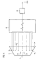
- FIG. 1 shows a gas turbine 1 in a longitudinal partial section. It has inside about a rotation axis. 2 rotatably mounted rotor 3, which also as a turbine rotor or Rotor shaft is called. Along the rotor 3 follow Intake housing 4, a compressor 5, a toroidal annular combustion chamber 6 with a plurality of coaxially arranged burners 7, a turbine 8 and an exhaust housing 9 to each other.
- annular compressor passage 10 is provided, in the direction of the annular combustion chamber 6 in cross section rejuvenated.
- a diffuser 11 is arranged, which communicates with the annular combustion chamber 6 is in fluid communication.
- the annular combustion chamber 6 forms a combustion chamber 12 for a mixture of a Fuel and compressed air L.
- a hot gas duct 13 is with the combustion chamber 12 in fluid communication, wherein the Hot gas duct 13, the exhaust housing 9 is arranged downstream.
- the exhaust duct 9 is delimited by an inner wall 24 which is concentric with the axis of rotation 2 and at which twenty-four temperature-measuring devices M i are arranged distributed uniformly over the circumference. All temperature measuring device M i lie in an imaginary plane which is perpendicular to the axis of rotation 2.
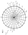
- FIG. 2 shows a Cartesian coordinate system P ( x, y ) with an outlet temperature distribution at a time t 0 .
- each auxiliary straight line H i based on the positive x-axis an angle ⁇ i, whose value is 15 ° or an integer multiple thereof.
- Detected for each of the temperature measuring devices M i T i temperature is entered on its associated auxiliary axis H i is a point whose distance from the origin P is proportional to (0.0) of the temperature T i to the detected amount.
- auxiliary axis H i 1..n, a point dependent on the local temperature T i results.
- T x i T i ⁇ cos ( ⁇ i )
- i 1..24
- T y i T i * Sin ( ⁇ i )
- i 1..24 a projection on the two axes of the coordinate system.
- the temperature measuring devices M i are all disposed lying in a plane which extends perpendicular to the axis of rotation 2 and thus simultaneously to the main flow direction of the exhaust gas. Another uneven distribution of the temperature measuring devices M i over the circumference would also be feasible with the method.
- equations (5) and (6) in equation (3) and equations (7) and (8) in equation (4) are used and transformed so that the reference value of the x-axis is and that of the y-axis
- the origin of the gravity vector, S ges lies in the coordinate origin P (0, 0) and ends in the center of gravity S, which lies at the point P (T xGL , T yGL ).
- the angle ⁇ ges is related to the positive x-axis in the mathematically positive sense, wherein the usual considerations for the size of the angle ⁇ ges are applied in the application of the tangent function.
- the points of the temperatures T i recorded on the auxiliary axes H i are connected to each other via a circumferential line 22, so that they together form a polygonal, almost circular area 23 whose center of gravity S is determined by application of the method.
- FIG. 3 shows the time profile of the center of gravity vector S ges shown in a combined amount-time and angle-time diagram.
- the focus vector S ges is determined by the amount S ges and the angle ⁇ ges , wherein the angle ⁇ ges in a dashed line type and the amount S ges is shown as a solid line.
- the angle ⁇ ges changes significantly and decreases approximately to half of its previous value.
- the apparatus for monitoring the center of gravity vector is shown S ges shown. It has an evaluation device 25, which applies the method.
- the evaluation device 25 is connected to all temperature measuring devices M i and to a display device 26. From the detected temperatures T i , the evaluation device 25 calculates the center of gravity vector S sat and check if its amount S ges or whose angle ⁇ ges is outside a tolerance interval. If this is the case, the evaluation device 25 generates a signal for the display device 26, which then displays a fault as the operating state.
- the display device 26 may be a monitor or a control lamp.
Landscapes
- Engineering & Computer Science (AREA)
- Physics & Mathematics (AREA)
- General Physics & Mathematics (AREA)
- Mechanical Engineering (AREA)
- General Engineering & Computer Science (AREA)
- Control Of Turbines (AREA)
- Testing Of Devices, Machine Parts, Or Other Structures Thereof (AREA)
- Measuring Temperature Or Quantity Of Heat (AREA)
Abstract
Description
Die Erfindung betrifft ein Verfahren zum Erkennen eines
Betriebszustandes beim Betrieb einer Turbine gemäss dem Oberbegriff
des Anspruchs 1 und eine Vorrichtung zur Durchführung
des Verfahrens gemäss dem Oberbegriff des Anspruchs 7.The invention relates to a method for detecting a
Operating state when operating a turbine according to the preamble
of claim 1 and an apparatus for implementation
of the method according to the preamble of
Es ist bekannt, dass zum Erkennen eines Betriebszustandes einer Turbine die im Abgas herrschenden Temperaturen kontinuierlich erfasst und ausgewertet werden. Dafür sind an der Innenwand des Abgasgehäuses koaxial gleichmäßig verteilte Temperatur-Messeinrichtungen angeordnet, die die Temperaturen des Abgases erfassen. Zur Bewertung der gemessenen Abgastemperaturen werden Extremwertevergleiche durchgeführt. Für jede Messstelle wird im Probebetrieb die maximal aufgetretene und die minimal aufgetretene Temperatur erfasst und somit ein Temperaturintervall bestimmt. Eine Störung wird dann festgestellt, wenn das Temperatur-Messelement eine Temperatur erfasst, die außerhalb ihres vorher gemessenen Temperaturintervalls liegt.It is known that for detecting an operating condition a turbine, the temperatures prevailing in the exhaust gas continuously recorded and evaluated. For that are at the Inner wall of the exhaust housing coaxially evenly distributed Temperature measuring devices arranged the temperatures of the exhaust gas. To evaluate the measured Exhaust gas temperatures are carried out extreme value comparisons. For each measuring point, the maximum is in trial operation occurred and recorded the minimum occurred temperature and thus determines a temperature interval. A disturbance will then detected when the temperature sensing element a Temperature recorded outside their previously measured Temperature interval is.
Auch bekannt ist, dass aus dem zeitlichen Temperaturmittelwert einer Temperatur-Messeinrichtung und der momentanen Temperatur die Differenz bestimmt wird, um den Betriebszustand zu ermitteln.It is also known that from the temporal average temperature a temperature measuring device and the current Temperature the difference is determined to the Determine operating status.
Diese Bewertungen haben den Nachteil, dass kleine systematische Veränderungen der Austrittstemperaturen, welche unterhalb der vorgegebenen Limits liegen, unberücksichtigt bleiben.These reviews have the disadvantage of being small systematic Changes in the outlet temperatures, which are below the predetermined limits are disregarded.
Aufgabe der vorliegenden Erfindung ist es daher, ein Verfahren zum Erkennen eines Betriebszustandes beim Betrieb einer Turbine anzugeben, mit dem systematische Veränderungen des Betriebszustandes erkennbar und anzeigbar sind. Ferner ist es Aufgabe der Erfindung, eine dazu korrespondierende Vorrichtung anzugeben.The object of the present invention is therefore a method for detecting an operating state during operation of a Turbine indicate with the systematic changes of the Operating state recognizable and can be displayed. It is further Object of the invention, a corresponding thereto Specify device.
Die Lösung der auf das Verfahren gerichteten Aufgabe wird durch die Merkmale des Anspruchs 1 gelöst. Vorteilhafte Weiterbildungen sind in den Unteransprüchen angegeben.The solution of the task directed to the method becomes solved by the features of claim 1. advantageous Further developments are specified in the subclaims.
Mit der Erfindung wird ein neuer Weg zum Erkennen eines Betriebszustandes beim Betrieb einer Turbine eingeschlagen. Bisher wurden im Abgaskanal an mehreren Positionen örtliche Temperaturmessungen vorgenommen, bei denen die Austrittstemperatur des Abgases erfasst wurde. Die örtliche Lage jeder erfassten Temperatur blieb dabei bisher unberücksichtig. Nun werden alle erfassten Temperaturen mit ihrer jeweils zugehörigen örtlichen Lage unter Momentbildung miteinander zu einer resultierenden Größe zusammengefasst, mittels der eine schnellere und genauere Erkennung von systematischen Veränderungen möglich ist.With the invention, a new way to recognize an operating condition taken during operation of a turbine. So far, in the exhaust duct at several locations local Temperature measurements made where the exit temperature of the exhaust gas was detected. The local situation each recorded temperature remained so far unconsidered. Now all recorded temperatures with their respective associated local situation under instantaneous formation combined into a resulting size, by means of a faster and more accurate detection of systematic changes is possible.
Die Abgastemperaturen eines Zeitpunktes werden unter Berücksichtung des Ortes, an dem sie erfasst werden, in ein Koordinatensystem eingetragen. Danach wird jeder Temperaturmesswert auf die beiden Achsen des Koordinatensystems projiziert und somit jeweils in zwei senkrecht zueinander dabei jeweils entweder positiv oder negativ gerichtete Ortskomponenten zerlegt, wobei anschließend für jede Achse die gleichgerichteten Ortskomponenten komponentenweise bezogen auf einen jeweiligen Bezugswert unter Momentbildung zu zwei Momentsummen aufsummiert werden, wobei jeder Bezugswert so gewählt ist, dass die entgegengerichteten Momentsummen gleich groß sind, und dass danach ein aus den beiden Bezugswerten zusammengesetzter Punkt als Schwerpunkt der Austrittstemperaturverteilung zum Erkennen des Betriebszustandes der Gasturbine ausgewertet wird. The exhaust gas temperatures of a time are under Taking into account the place where they are recorded, in one Coordinate system entered. After that everyone will Temperature reading on the two axes of the Coordinate system projected and thus in two perpendicular to each other either positive or decomposed negative-oriented spatial components, where then the rectified for each axis Location components component by component relative to a respective Reference value under torque formation to two torque sums be summed with each reference chosen that the opposing momentums are the same size, and then one of the two reference values composite point as the focus of the Outlet temperature distribution for detecting the Operating state of the gas turbine is evaluated.
Durch die Nutzung der Gesamtinformationen der Austrittstemperaturverteilung
werden die Informationen, die bisher
unterhalb der Minimalbedingungen lagen, berücksichtigt.
Daraus ergibt sich ein höherer Informationsgehalt, der zur
einer schnelleren und besseren Zustandserkennung genutzt
wird.By using the total information of the outlet temperature distribution, the information that was previously below the minimum conditions is taken into account.
This results in a higher information content, which is used for a faster and better state recognition.
In einer vorteilhaften Ausgestaltung wird der Betriebszustand während eines stationären Betriebes der Gasturbine als eine Störung erkannt, wenn der Schwerpunkt als Vektor mit Betrag und Winkel darstellbar ist, und wenn der aktuelle Betrag - oder Winkel -, des Schwerpunktvektors bezogen auf einen zu einem früheren Zeitpunkt bestimmten Betrag - oder Winkel -, eine Differenz aufweist, die einen Toleranzwert überschreitet bzw. unterschreitet. Es werden zwei zu unterschiedlichen Zeitpunkten erfasste Schwerpunkte miteinander verglichen, deren Differenz überwacht wird. Überschreitet die Differenz einen Toleranzwert, wird eine Störung des Betriebes der Turbine erkannt. Die Toleranzwerte werden durch Testbetriebe oder durch Erfahrungswerte ermittelt.In an advantageous embodiment, the operating state during stationary operation of the gas turbine as a Disturbance detected when the center of gravity as a vector with amount and angle is representable, and if the current amount - or angle, of the centroid vector relative to one an earlier time determined amount - or angle -, has a difference that exceeds a tolerance value or falls below. There are two to different Time points were compared, whose difference is monitored. Exceeds the difference a tolerance value, a malfunction of the operation of Turbine detected. The tolerance values are determined by test farms or determined by empirical values.
In umgekehrter Betrachtung kann ein ungestörter Betrieb der Gasturbine diagnostiziert werden, wenn der Schwerpunktvektor über die Zeit betrachtet konstant in Betrag und/oder Winkel bleibt.Conversely, undisturbed operation of the Gas turbine to be diagnosed when the center of gravity vector considered constant over time in amount and / or angle remains.
Das zeitliche Verhalten des Betrages und des Winkels des Schwerpunktvektors - der Schwerpunkt der Austrittstemperaturverteilung - weist im Betrieb der Turbine ein bekanntes Verhalten auf:The temporal behavior of the amount and the angle of the Focus vector - the focus of the Outlet temperature distribution - indicates during operation of the turbine a known behavior on:
Im störungsfreien Betrieb der Gasturbine schwingt sich der Schwerpunktvektor der Austrittstemperaturverteilung auf einen zeitlichen konstanten Betrag mit einem konstanten Winkel ein. Konstant bedeutet dabei, dass zwar innerhalb der durch Toleranzwerte vorgegebenen Schwankungsbreite geringe Änderungen auftreten können, die jedoch auf nicht systematische, sondern auf zufällige Einflüsse zurückzuführen sind.In trouble-free operation of the gas turbine oscillates the Focus vector of the outlet temperature distribution on a temporal constant amount at a constant angle. Constant means that while within the by Tolerance values given fluctuation range low Changes may occur, however, not on systematic, but due to accidental influences are.
Treten Laständerungen auf, sind diese ohne Einfluss auf den Betrag des Schwerpunktvektors, da der Betrag grundsätzlich eine Invarianz gegenüber Laständerungen aufweist.If load changes occur, these are without influence on the Amount of the main vector, as the amount in principle has an invariance to load changes.
Der Winkel des Schwerpunktvektors ist grundsätzlich abhängig von Laständerungen, da sich mit diesen ebenfalls der Heißgasmassenstrom und damit die Strömungsverhältnisse in der Turbine verändern. Die Veränderung des Heißgasmassenstromes erfolgt durch die Verstellungen der Verdichter-Vorleitschaufeln und/oder durch die Variation des zugeführten Brennstoffmassenstromes.The angle of the gravity vector is basically dependent of load changes, since with these also the Hot gas mass flow and thus the flow conditions in the Turbine change. The change of the hot gas mass flow is done by the adjustments of the compressor-Vorleitschaufeln and / or by the variation of the supplied Fuel mass flow.
Die Veränderungen des Heißgasmassenstromes bewirken eine entsprechende Drehung der Austrittstemperaturverteilung. Dies ist jedoch nicht gleichbedeutend mit einer Störung, da diese Winkeländerung auf bekannte Eingriffe in den Betrieb der Gasturbine zurückzuführen ist.The changes in the hot gas mass flow cause a corresponding rotation of the outlet temperature distribution. This However, this is not synonymous with a disorder, since this Angle change to known interventions in the operation of the Gas turbine is due.
Ändert sich während des stationären Betriebes der Turbine der Betrag oder der Winkel des Schwerpunktvektors wesentlich, so ist dies auf eine systematische Veränderung wie zum Beispiel auf die Kanalverblockung durch einen gelösten Hitzeschildstein zurückzuführen. Die systematischen Veränderungen sind auf einen fehlerbehafteten Betrieb oder auf eine Störung der Gasturbine zurückzuführen, da ein bekannter, äußerer Einfluss fehlt. Ferner führen Brennerstörungen, die Düsenverkokung einerseits oder eine veränderte Flammausrichtung anderseits sein können, zu einem sich verändernden Schwerpunkt der Austrittstemperaturverteilung. Gleichfalls können Strömungsfluktuationen, die sich in Temperaturfluktuationen niederschlagen, zu der Rotation des Winkels führen. Changes during stationary operation of the turbine Amount or the angle of the gravity vector essential, so this is due to a systematic change such as on the Kanalverblockung by a dissolved Attributed to heat shield stone. The systematic Changes are due to a faulty operation or due to a fault in the gas turbine, as a known, external influence is missing. Further lead Burner damage, the Düsenverkokung one hand or a On the other hand, altered flame orientation can be to one changing focus of Exit temperature distribution. Likewise Flow fluctuations resulting in temperature fluctuations knock down, lead to the rotation of the angle.
Zweckmäßigerweise ist eine Ebene, in der die Messstellen für die Temperatur-Messeinrichtungen liegen, senkrecht zur Hauptströmungsrichtung des Abgases ausgerichtet und die Hauptströmungsrichtung parallel zur Drehachse einer Welle der Turbine. Die Temperaturen werden demnach im identischen Abstand zur Drehachse der Welle zeitlich verfolgt.Conveniently, a level in which the measuring points for the temperature measuring devices are perpendicular to the main flow direction the exhaust gas aligned and the main flow direction parallel to the axis of rotation of a shaft of Turbine. The temperatures are therefore identical Distance tracked to the axis of rotation of the shaft.
In einer vorteilhaften Weiterbildung sind die Messstellen rotationssymmetrisch zur Drehachse angeordnet. Eine äquidistante Verteilung wird hierdurch erreicht, die wegen der Symmetrie besonders einfach auswertbar ist.In an advantageous development, the measuring points are rotationally symmetrical arranged to the axis of rotation. A Equidistant distribution is achieved thereby, because of the symmetry is particularly easy to evaluate.
Generell ist das Verfahren für die ständige Überwachung des Betriebes geeignet. Dabei ist es ganz besonders vorteilhaft, wenn das Verfahren bevorzugt während des stationären oder quasi-stationären Betriebes der Turbine zu jedem Zeitpunkt d.h. kontinuierlich angewendet wird, da das Verfahren hier besonders zuverlässige Resultate liefert. Die Zustandsanalyse des Gasturbinenbetriebes mit Hilfe des Schwerpunktvektors ist jedoch prinzipiell auch in einem stark transienten Betrieb - unter geeigneten Modifikationen - durchführbar, wobei es im transienten Betrieb Besonderheiten zu berücksichtigen gilt. Zuverlässige Ergebnisse und Aussagen über das Verhalten der Gasturbine bei Durchlaufen eines transienten Betriebszustands, z.B. Anfahrvorgänge und Abfahrvorgänge, können mithin im Detail untersucht werden.In general, the procedure for constant monitoring of the Operation suitable. It is especially advantageous if the process is preferred during stationary or quasi-stationary operation of the turbine at any time i.e. is applied continuously, since the procedure here provides particularly reliable results. The state analysis of the gas turbine operation with the aid of the center of gravity vector but in principle also in a strong transient operation - under suitable modifications - feasible, it being in the transient operation specifics must be considered. Reliable results and statements about the behavior of Gas turbine on passing through a transient Operating state, e.g. Start-ups and shutdowns, can therefore be examined in detail.
Zweckmäßigerweise ist die Turbine als Gasturbine ausgebildet.Conveniently, the turbine is designed as a gas turbine.
Die auf die Vorrichtung gerichtete Aufgabe wird durch die
Merkmale des Anspruchs 7 gelöst. Vorteilhafte Weiterbildungen
sind in den Unteransprüchen angegeben.The object directed to the device is achieved by the
Characteristics of
Jede Temperatur-Messeinrichtung ist mit einem Eingang einer einzigen Auswerteeinrichtung verbunden, mit der ein Betriebszustand charakterisierbar ist. In der Auswerteeinrichtung wird dann das beschriebene Verfahren durchgeführt, so dass am Ausgang der Auswerteeinrichtung demgemäss ein Signal für den Betriebszustand anzeigbar ist. Daher weist die Auswerteeinrichtung Mittel zur Aufnahme der erfassten Temperatur und Mittel zur Kenntlichmachung des Betriebszustandes auf.Each temperature measuring device is connected to an input of a single evaluation device connected to the one Operating condition can be characterized. In the Evaluation is then the described method performed so that at the output of the evaluation Accordingly, a signal for the operating state can be displayed. Therefore, the evaluation device has means for receiving the recorded temperature and means of identification of the Operating state on.
In einer vorteilhaften Weiterbildung steht eine Ebene, in der die Temperatur-Messeinrichtungen vorgesehen sind, quer zur Hauptströmungsrichtung des Abgases, welche parallel zur Drehachse einer Welle der Turbine verläuft. Die in der Ebene liegenden Temperatur-Messeinrichtungen sind an der Innenwand des Abgasgehäuses vorgesehen, so dass alle örtlichen Temperaturmesswerte im gleichen Abstand zur Drehachse der Welle erfasst. Dadurch werden identische Bedingungen für die Temperatur-Messeinrichtungen geschaffen; eine Gewichtung einzelner Temperaturmesswerte ist nicht erforderlich.In an advantageous development is a level in the the temperature measuring means are provided, transverse to Main flow direction of the exhaust gas, which parallel to Rotary axis of a shaft of the turbine runs. The in the plane lying temperature measuring devices are on the inner wall the exhaust housing provided so that all local Temperature readings equidistant to the axis of rotation of the Wave detected. This will be identical conditions for the Temperature measuring devices created; a weighting individual temperature readings is not required.
Zweckmäßigerweise sind die örtlichen Temperaturmesswerte rotationssymmetrisch zur Drehachse erfassbar.Conveniently, the local temperature measurements are rotationally symmetric detectable to the axis of rotation.
Wenn die Turbine eine Ringbrennkammer aufweist, an der eine Anzahl von Brennern vorgesehen ist und die Anzahl der Brenner gleich der Anzahl von Temperatur-Messeinrichtungen ist, kann eine Relation von Brennern zur im Abgaskanal gemessenen Abgastemperatur hergestellt werden.If the turbine has an annular combustion chamber, at the one Number of burners is provided and the number of burners is equal to the number of temperature measuring devices can a relation of burners to the exhaust gas temperature measured in the exhaust duct getting produced.
Weist die Turbine eine Anzahl von Brennkammern mit jeweils einem Brenner auf, so kann eine Relation von Brennern zur im Abgaskanal gemessenen Abgastemperatur auch über eine Anzahl von Temperatur-Messeinrichtungen erreicht werden, wenn diese der Anzahl von Brennkammern entspricht.Does the turbine with a number of combustion chambers with each On a burner, so can a relation of burners in the Exhaust gas channel measured exhaust gas temperature also over a number be reached by temperature measuring equipment, if this the number of combustion chambers.
Vorteilhafterweise ist die Turbine als Gasturbine ausgebildet.Advantageously, the turbine is designed as a gas turbine.
Die Erfindung wird anhand einer Zeichnung näher erläutert. Dabei zeigen:
- Figur 1
- eine Gasturbine in einem Längsteilschnitt,
Figur 2- ein kartesisches Koordinatensystem mit einem Diagramm der Austrittstemperaturverteilung,
Figur 3- ein kombiniertes Betrag-Zeit und Winkel-Zeit-Diagramm für einen Schwerpunktvektor der Austrittstemperaturverteilung der Gasturbine und
- Figur 4
- eine Auswerteeinrichtung für das Überwachungsverfahren
- FIG. 1
- a gas turbine in a longitudinal section,
- FIG. 2
- a Cartesian coordinate system with a diagram of the outlet temperature distribution,
- FIG. 3
- a combined magnitude-time and angle-time diagram for a gravity vector of the exit temperature distribution of the gas turbine and
- FIG. 4
- an evaluation device for the monitoring method
Die Figur 1 zeigt eine Gasturbine 1 in einem Längsteilschnitt.
Sie weist im Inneren einen um eine Rotationsachse 2
drehgelagerten Rotor 3 auf, der auch als Turbinenläufer oder
Rotorwelle bezeichnet wird. Entlang des Rotors 3 folgen ein
Ansauggehäuse 4, ein Verdichter 5, eine torusartige Ringbrennkammer
6 mit mehreren koaxial angeordneten Brennern 7,
eine Turbine 8 und ein Abgasgehäuse 9 aufeinander.FIG. 1 shows a gas turbine 1 in a longitudinal partial section.
It has inside about a rotation axis. 2
rotatably mounted
Im Verdichter 5 ist ein ringförmiger Verdichterkanal 10 vorgesehen,
der sich in Richtung der Ringbrennkammer 6 im Querschnitt
verjüngt. Am brennkammerseitigen Ausgang des Verdichters
5 ist ein Diffusor 11 angeordnet, der mit der Ringbrennkammer
6 in Strömungsverbindung steht. Die Ringbrennkammer 6
bildet einen Verbrennungsraum 12 für ein Gemisch aus einem
Brennstoff und verdichteter Luft L. Ein Heißgaskanal 13 ist
mit dem Verbrennungsraum 12 in Strömungsverbindung, wobei dem
Heißgaskanal 13 das Abgasgehäuse 9 nachgeordnet ist.In the
Im Verdichterkanal 10 und im Heißgaskanal 13 sind jeweils alternierend
Schaufelringe angeordnet. Einem aus Leitschaufeln
14 gebildeter Leitschaufelring 15 folgt jeweils ein aus Laufschaufeln
16 geformte Laufschaufelring 17. Die feststehenden
Leitschaufeln 14 sind dabei mit dem Stator 18 verbunden, wo
hingegen die Laufschaufeln 16 am Rotor 3 mittels einer Turbinenscheibe
19 befestigt sind.In the
Der Abgaskanal 9 wird durch eine zur Rotationsachse 2
konzentrische Innenwand 24 begrenzt, an der drehfest
vierundzwanzig Temperatur-Messeinrichtungen Mi über den
Umfang gleichverteilt angeordnet sind. Alle Temperatur-Messeinrichtung
Mi liegen dabei in einer gedachten Ebene, die
senkrecht zur Rotationsachse 2 steht.The
Während des Betriebes der Gasturbine 1 wird vom Verdichter 5
durch das Ansauggehäuse 4 Luft L angesaugt und im Verdichterkanal
10 verdichtet. Die am brennerseitigen Ausgang des
Verdichters 5 bereitgestellt Luft L wird durch den Diffusor
11 zu den Brennern 7 geführt und dort mit einem Brennstoff
vermischt. Das Gemisch wird dann unter Bildung eines
Arbeitsfluids 20 im Verbrennungsraum 10 verbrannt. Von dort
aus strömt das Arbeitsfluid 20 in den Heißgaskanal 13. An den
in der Turbine 8 angeordneten Leitschaufeln 16 und an den
Laufschaufeln 18 entspannt sich das Arbeitsfluid 20
impulsübertragend, so dass der Rotor 3 angetrieben wird und
mit ihm eine an ihn angekoppelte Arbeitsmaschine (nicht
dargestellt). Im Abgaskanal 9 wird das Arbeitsfluid 20 als
Abgas weitergeleitet. Jede Temperatur-Messeinrichtung Mi
misst dann die an ihrem Ort herrschende Temperatur Ti des
Abgases.During operation of the gas turbine 1 4 air L is sucked by the
Figur 2 zeigt ein kartesisches Koordinaten-System P(x,y) mit einer Austrittstemperaturverteilung zu einem Zeitpunkt t0.FIG. 2 shows a Cartesian coordinate system P ( x, y ) with an outlet temperature distribution at a time t 0 .
Es wird definiert:
- P(x,y) :=
- ein in der Ebene liegendes kartesisches
Koordinaten-System, das
von der Rotationsachse 2 im Koordinatenursprung P(0,0) senkrecht geschnitten wird - Mi :=
- die Temperatur-Messeinrichtungen, deren Messstellen in der Ebene liegen
- n :=
- 24, die Anzahl der Temperatur-Messeinrichtungen,
- Ti : =
- Temperatur der Temperatur-Messeinrichtung Mi, für i=1..n
- P (x, y): =
- an in-plane Cartesian coordinate system perpendicularly intersected by the
rotation axis 2 at the coordinate origin P (0,0) - M i : =
- the temperature measuring devices whose measuring points lie in the plane
- n: =
- 24, the number of temperature measuring equipment,
- T i : =
- Temperature of the temperature measuring device M i , for i = 1..n
Im Koordinatensystem P(x,y) erstrecken sich strahlenförmig vom Koordinatenursprung P(0,0) vierundzwanzig Hilfsgeraden Hi, für i=1..n, zu jeder Messstelle der Temperatur-Messeinrichtungen Mi. Somit weist jede Hilfsgerade Hi bezogen auf die positive x-Achse einen Winkel Θi auf, dessen Wert 15° oder ein ganzzahliges Vielfaches davon beträgt.In the coordinate system P (x, y) radiate from the coordinate origin P (0,0) twenty-four auxiliary lines H i , for i = 1..n, to each measuring point of the temperature measuring devices M i . Thus, each auxiliary straight line H i based on the positive x-axis an angle Θ i, whose value is 15 ° or an integer multiple thereof.
Für jede von den Temperatur-Messeinrichtungen Mi erfasste
Temperatur Ti wird auf ihrer zugehörigen Hilfsachse Hi ein
Punkt eingetragen, dessen Abstand vom Koordinatenursprung
P (0,0) proportional zum erfassten Betrag der Temperatur Ti
ist. Somit ergibt sich auf jeder Hilfsachse Hi, i=1..n, ein
von der örtlichen Temperatur Ti abhängiger Punkt. Für jeden
Punkt erfolgt dann mittels der bekannten trigonometrischen
Funktionen gemäß
Um eine identische Gewichtung aller ermittelten Temperaturen
Ti zu erzielen, sind die Temperatur-Messeinrichtungen Mi alle
in einer Ebene liegend angeordnet, die sich senkrecht zur
Drehachse 2 und damit gleichzeitig zur Hauptströmungsrichtung
des Abgases sich erstreckt. Eine andere ungleichmäßige
Verteilung der Temperatur-Messeinrichtungen Mi über den
Umfang wäre ebenfalls mit dem Verfahren durchführbar. In order to achieve an identical weighting of all determined temperatures T i , the temperature measuring devices M i are all disposed lying in a plane which extends perpendicular to the axis of
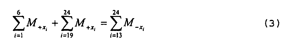
Um einen Schwerpunkt S der Austrittstemperaturverteilung des
Abgases bestimmen zu können, müssen die Momente der einzelnen
Temperaturen Ti um den Schwerpunkt S herum im Gleichgewicht
stehen. Bei der komponentenweisen Betrachtung, d.h. für jede
Achse des Koordinatensystems in jede Richtung, müssen
demgemäss jeweils die Summen der entgegengesetzt gerichteten
Momente gemäß
![]()
![]()
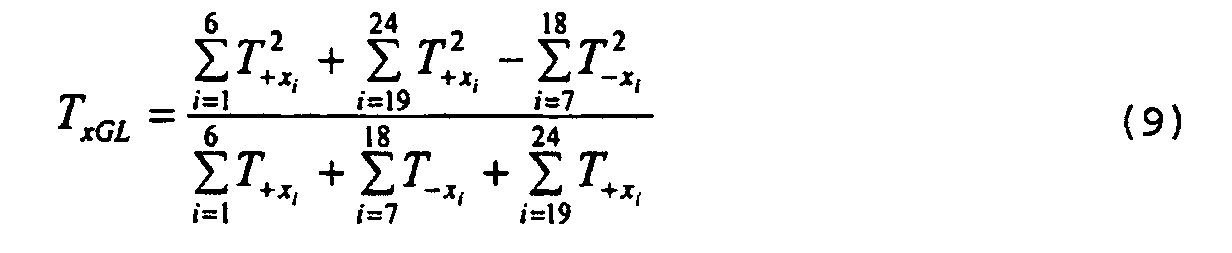
Zur Berechnung des Schwerpunktes S werden die Gleichungen (5)
und (6) in Gleichung (3) und die Gleichungen (7) und (8) in
Gleichung (4) eingesetzt und umgeformt, so dass der
Bezugswert der x-Achse sich nach
Die beiden Bezugswerte lassen sich dann als einen
Schwerpunktvektor 
Zeitaufgelöst - d.h. immer wiederkehrend werden alle
ermittelten Temperaturen Ti gemäss der obigen Rechnung zu
einem Schwerpunktvektor
In Figur 2 sind die Punkte der auf den Hilfsachsen Hi
eingetragenen Temperaturen Ti über eine Umfangslinie 22
miteinander verbunden, so dass sie gemeinsam eine vieleckige,
fast kreisförmige Fläche 23 einschließen, deren Schwerpunkt S
durch Anwendung des Verfahrens bestimmt wird. In FIG. 2, the points of the temperatures T i recorded on the auxiliary axes H i are connected to each other via a
Für eine ideale Gasturbine 1 mit einer symmetrischen Austrittstemperaturverteilung
müsste sich als Schwerpunktvektor
Vergrößert sich der Betrag
In Figur 3 ist der zeitliche Verlauf des Schwerpunktvektors
Im stationären ungestörten Betrieb der Gasturbine ab dem
Zeitpunkt t=t0 bis zum Zeitpunkt t=t1 verläuft die Kennlinie
des Betrages
Zum Zeitpunkt t=t1 tritt während des stationären Betriebs durch eine Teilblockade des Turbineneintrittraums eine systematische Veränderung ein, die mittels des Verfahren erkannt wird.At time t = t 1 occurs during stationary operation by a partial blockage of the turbine inlet space, a systematic change, which is detected by the method.
Ab dem Zeitpunkt t=t1 ändert sich der Winkel ϕges wesentlich
und sinkt ungefähr auf die Hälfte seines vorherigen Wertes
ab. Der Betrag
Mit den bisher aus dem Stand der Technik bekannten Überwachungsverfahren sind zwar die Temperaturänderungen notiert worden, jedoch überschritten die geringen systematischen Temperaturänderungen nicht die Grenzwerte, so dass kein fehlerhafter Betrieb diagnostiziert wurde. Daher wurde dieser Störfall - die Teilblockade des Turbineneintrittraums mit daraus resultierender Oszillationsanregungen der ersten Laufschaufelreihe und anschließenden Schaufelbrüchen - nicht früh genug erkannt.With the hitherto known from the prior art Although monitoring procedures are the temperature changes however, the small ones have been exceeded systematic temperature changes do not exceed the limits, so that no faulty operation was diagnosed. Therefore was this incident - the partial blockade of Turbine inlet space with resulting Oszillationsanregungen the first blade row and subsequent blade breaks - not recognized soon enough.
In Figur 4 ist die Vorrichtung zum Überwachen des
Schwerpunktvektors
Durch die stetige Überwachung des Betrages
Claims (12)
bei dem ein heißes Abgas durch ein der Turbine (1) nachgeschaltetes Abgasgehäuse (9) strömt und die Temperatur des Abgases im Abgasgehäuse (9) zeitaufgelöst erfasst wird,
dadurch gekennzeichnet, dass
in einer Ebene quer zur Hauptströmungsrichtung des Abgases eine Anzahl von Temperaturmesswerten des Abgases bezogen auf einen Ursprung eines gedachten kartesischen Koordinatensystems jeweils ortsaufgelöst erfasst wird,
dass die Temperaturmesswerte auf die beiden Achsen des Koordinatensystems projiziert und somit jeweils in zwei senkrecht zueinander dabei jeweils entweder positiv oder negativ gerichtete Ortskomponenten zerlegt werden, wobei für jede Achse die gleichgerichteten Ortskomponenten anschließend komponentenweise bezogen auf einen jeweiligen Bezugswert unter Momentbildung zu zwei Momentsummen aufsummiert werden, wobei jeder Bezugswert so gewählt ist, dass die entgegengerichteten Momentsummen gleich groß sind, und
dass danach ein aus den beiden Bezugswerten zusammengesetzter Punkt als Schwerpunkt der Temperaturverteilung zum Erkennen des Betriebszustandes ausgewertet wird.Method for detecting an operating state during operation of a turbine (1),
in which a hot exhaust gas flows through an exhaust gas housing (9) arranged downstream of the turbine (1) and the temperature of the exhaust gas in the exhaust gas housing (9) is detected in a time-resolved manner,
characterized in that
in a plane transverse to the main flow direction of the exhaust gas, a number of temperature measured values of the exhaust gas relative to an origin of an imaginary Cartesian coordinate system are respectively detected spatially resolved,
in that the temperature measured values are projected onto the two axes of the coordinate system and thus in each case split into two locally positive or negative local components, wherein for each axis the rectified local components are then summed component by component relative to a respective reference value under torque formation to two torque sums, each reference value being chosen so that the opposing momentums are equal, and
that thereafter a point composed of the two reference values is evaluated as the center of gravity of the temperature distribution for detecting the operating state.
dadurch gekennzeichnet, dass der Schwerpunkt als Vektor mit Betrag und Winkel darstellbar ist, und dass der Betriebszustand als eine Störung erkannt wird, wenn der aktuelle Betrag - oder Winkel - des Schwerpunktvektors bezogen auf einen eines zu einem früheren Zeitpunkt gemessenen Betrag eine Differenz aufweist, die einen Toleranzwert überschreitet.Method according to claim 1
characterized in that the center of gravity can be represented as a vector with magnitude and angle, and that the operating state is recognized as a disturbance if the current magnitude - or angle - of the centroid vector relative to an amount measured at an earlier time has a difference exceeds a tolerance value.
dadurch gekennzeichnet, dass
die Ebene senkrecht zur Hauptströmungsrichtung des Abgases steht und die Hauptströmungsrichtung parallel zur Drehachse (2) einer welle der Turbine (1) verläuft.Method according to claim 1 or 2,
characterized in that
the plane is perpendicular to the main flow direction of the exhaust gas and the main flow direction is parallel to the rotation axis (2) of a shaft of the turbine (1).
dadurch gekennzeichnet, dass
alle örtlichen Temperaturmesswerte im gleichen Abstand zur Drehachse (2) der Welle erfasst werden.Method according to claim 1, 2 or 3,
characterized in that
all local temperature measured values are to be detected at the same distance to the axis of rotation (2) of the shaft.
dadurch gekennzeichnet, dass
die örtlichen Temperaturmesswerte rotationssymmetrisch zur Drehachse (2) erfasst werden.Method according to one of the preceding claims,
characterized in that
the local temperature measured values are recorded rotationally symmetrical to the axis of rotation (2).
dadurch gekennzeichnet, dass
es während des stationären Betriebes der Turbine (1) angewendet wird.Method according to one of the preceding claims,
characterized in that
it is applied during stationary operation of the turbine (1).
bei der eine Anzahl von Temperatur-Messeinrichtungen (T) in einem Abgasgehäuse (9) einer Turbine (1) in einer Ebene quer zur Strömungsrichtung des Abgases angeordnet sind, mit denen lokal ein jeweiliger Temperaturmesswert zeitaufgelöst erfassbar ist,
dadurch gekennzeichnet, dass
jede Temperatur-Messeinrichtung (T) mit einem Eingang einer Auswerteeinrichtung (25) verbunden ist, mit der ein Betriebszustand charakterisierbar ist, und dass an einem Ausgang der Auswerteeinrichtung (25) ein Signal für den Betriebszustand anzeigbar ist.Device for carrying out the method according to one of claims 1 to 6,
in which a number of temperature measuring devices (T) are arranged in an exhaust gas housing (9) of a turbine (1) in a plane transverse to the flow direction of the exhaust gas, with which a respective temperature measured value can be detected locally in a time-resolved manner,
characterized in that
each temperature measuring device (T) is connected to an input of an evaluation device (25), with which an operating state can be characterized, and in that an output signal of the evaluation device (25) can be displayed for the operating state.
dadurch gekennzeichnet, dass
die Ebene quer zur Hauptströmungsrichtung des Abgases steht, die Hauptströmungsrichtung parallel zur Drehachse (2) einer Welle der Turbine (1) ist,
dass alle örtlichen Temperaturmesswerte im gleichen Abstand zur Drehachse (2) der Welle erfassbar sind.Device according to claim 7,
characterized in that
the plane is transverse to the main flow direction of the exhaust gas, the main flow direction is parallel to the rotation axis (2) of a shaft of the turbine (1),
that all local temperature measured values can be detected at the same distance from the axis of rotation (2) of the shaft.
dadurch gekennzeichnet, dass
die örtlichen Temperaturmesswerte rotationssymmetrisch zur Drehachse (2) erfassbar sind.Device according to claim 7 or 8,
characterized in that
the local temperature measurements are rotationally symmetrical to the axis of rotation (2) can be detected.
dadurch gekennzeichnet, dass
die Turbine (1) eine Ringbrennkammer (6) aufweist, an der eine Anzahl von Brennern (7) vorgesehen ist, und
dass die Anzahl von Brennern (7) gleich der Anzahl von Messelementen ist.Apparatus according to claim 7, 8 or 9,
characterized in that
the turbine (1) has an annular combustion chamber (6) on which a number of burners (7) are provided, and
the number of burners (7) is equal to the number of measuring elements.
dadurch gekennzeichnet, dass
die Turbine (1) eine Anzahl von Brennkammern (6) mit jeweils einem Brenner (7) aufweist, und dass die Anzahl von Brennkammern (6) gleich der Anzahl von Messelementen ist.Apparatus according to claim 7, 8 or 9,
characterized in that
the turbine (1) has a number of combustion chambers (6) each with a burner (7), and that the number of combustion chambers (6) is equal to the number of measuring elements.
dadurch gekennzeichnet, dass
die Turbine (1) als Gasturbine ausgebildet ist.Device according to one of claims 1 to 11,
characterized in that
the turbine (1) is designed as a gas turbine.
Priority Applications (7)
| Application Number | Priority Date | Filing Date | Title |
|---|---|---|---|
| EP03019868A EP1510656A1 (en) | 2003-09-01 | 2003-09-01 | Method and system for identifying an operational mode of a gas turbine |
| EP04763460A EP1660759B1 (en) | 2003-09-01 | 2004-07-23 | Method for identifying the operating condition of a turbine |
| US10/570,514 US7899647B2 (en) | 2003-09-01 | 2004-07-23 | Method and device for identifying the operating condition of a turbine |
| ES04763460T ES2302018T3 (en) | 2003-09-01 | 2004-07-23 | PROCEDURE TO RECOGNIZE A STATE OF OPERATION OF A TURBINE. |
| PCT/EP2004/008290 WO2005028814A1 (en) | 2003-09-01 | 2004-07-23 | Method and device for identifying the operating condition of a turbine |
| DE502004006601T DE502004006601D1 (en) | 2003-09-01 | 2004-07-23 | ER TURBINE |
| CN2004800234850A CN1836092B (en) | 2003-09-01 | 2004-07-23 | Method for detecting working state of turbine |
Applications Claiming Priority (1)
| Application Number | Priority Date | Filing Date | Title |
|---|---|---|---|
| EP03019868A EP1510656A1 (en) | 2003-09-01 | 2003-09-01 | Method and system for identifying an operational mode of a gas turbine |
Publications (1)
| Publication Number | Publication Date |
|---|---|
| EP1510656A1 true EP1510656A1 (en) | 2005-03-02 |
Family
ID=34089657
Family Applications (2)
| Application Number | Title | Priority Date | Filing Date |
|---|---|---|---|
| EP03019868A Withdrawn EP1510656A1 (en) | 2003-09-01 | 2003-09-01 | Method and system for identifying an operational mode of a gas turbine |
| EP04763460A Expired - Lifetime EP1660759B1 (en) | 2003-09-01 | 2004-07-23 | Method for identifying the operating condition of a turbine |
Family Applications After (1)
| Application Number | Title | Priority Date | Filing Date |
|---|---|---|---|
| EP04763460A Expired - Lifetime EP1660759B1 (en) | 2003-09-01 | 2004-07-23 | Method for identifying the operating condition of a turbine |
Country Status (6)
| Country | Link |
|---|---|
| US (1) | US7899647B2 (en) |
| EP (2) | EP1510656A1 (en) |
| CN (1) | CN1836092B (en) |
| DE (1) | DE502004006601D1 (en) |
| ES (1) | ES2302018T3 (en) |
| WO (1) | WO2005028814A1 (en) |
Cited By (4)
| Publication number | Priority date | Publication date | Assignee | Title |
|---|---|---|---|---|
| DE102006019578A1 (en) * | 2006-04-27 | 2007-10-31 | Abb Patent Gmbh | Gas or air temperature measurement device for use in low-voltage switching cabinet, has several temperature sensors that are fixed to places, which are arranged in matrix-shape, in evenly distributed manner and arranged above housing |
| WO2011039153A1 (en) * | 2009-09-29 | 2011-04-07 | Siemens Aktiengesellschaft | Device generating exhaust gas, especially a boat, comprising a system for determining the volume of exhaust gas |
| EP1777394A3 (en) * | 2005-10-24 | 2012-06-20 | General Electric Company | Gas turbine engine combustor hot streak control |
| WO2019052734A1 (en) * | 2017-09-14 | 2019-03-21 | Siemens Aktiengesellschaft | METHOD FOR DETECTING AN INCORRECTION OF THE WINKELLAGE OF A COMPRESSOR PIPE ARRANGED IN A COMPRESSOR AND SWITCHED AROUND THEIR LENGTH AXIS |
Families Citing this family (9)
| Publication number | Priority date | Publication date | Assignee | Title |
|---|---|---|---|---|
| EP3199781B1 (en) * | 2016-01-27 | 2019-05-01 | Ansaldo Energia IP UK Limited | A gas turbine and a corresponding method for controlling a gas turbine operation with seleceted turbine outlet temperature sensors |
| DE102017101161A1 (en) * | 2017-01-23 | 2018-07-26 | Man Diesel & Turbo Se | gas turbine |
| IT201700028071A1 (en) * | 2017-03-14 | 2018-09-14 | Nuovo Pignone Tecnologie Srl | METHODS FOR DETECTING A FAULT IN A BURNER OF A COMBUSTOR AND TURBINE SYSTEM |
| EP3531019A1 (en) * | 2018-02-27 | 2019-08-28 | Siemens Aktiengesellschaft | Analysis method for a gas turbine |
| RU2696919C1 (en) * | 2018-04-18 | 2019-08-07 | Акционерное общество "РОТЕК" (АО "РОТЕК") | Method and system for assessment of technical condition of gas turbine units based on temperature fields |
| US11352077B2 (en) * | 2018-12-31 | 2022-06-07 | Contitech Transportbandsysteme Gmbh | Tethered temperature sensor for use in rubber embedded applications |
| CN112903301B (en) * | 2019-12-04 | 2023-09-15 | 西门子能源国际公司 | Method and device for identifying gas turbine operating status |
| JP7657670B2 (en) * | 2021-07-05 | 2025-04-07 | 東芝エネルギーシステムズ株式会社 | Damage assessment device and damage assessment method |
| CN117391160A (en) * | 2022-07-01 | 2024-01-12 | 阿里巴巴(中国)有限公司 | Acceleration methods, accelerators and storage media |
Citations (6)
| Publication number | Priority date | Publication date | Assignee | Title |
|---|---|---|---|---|
| GB989011A (en) * | 1961-02-16 | 1965-04-14 | Bbc Brown Boveri & Cie | Apparatus for controlling the operation of a machine |
| JPH0264232A (en) * | 1988-08-30 | 1990-03-05 | Hitachi Ltd | Gas turbine combustor monitoring and display device |
| US5878566A (en) * | 1994-12-05 | 1999-03-09 | Hitachi, Ltd. | Gas turbine and a gas turbine control method |
| DE19821956A1 (en) * | 1998-05-16 | 1999-11-18 | Deutsch Zentr Luft & Raumfahrt | Method for the quantitative analysis of gas volumes, in particular exhaust gases from combustion devices or systems, and devices for carrying out the method |
| EP1118920A1 (en) * | 2000-01-20 | 2001-07-25 | General Electric Company | Machine protection system for rotating equipment and method |
| US20020183916A1 (en) * | 2000-08-30 | 2002-12-05 | General Electric Company. | Method and system for identifying malfunctioning combustion chambers in a gas turbine |
Family Cites Families (6)
| Publication number | Priority date | Publication date | Assignee | Title |
|---|---|---|---|---|
| US4735052A (en) * | 1985-09-30 | 1988-04-05 | Kabushiki Kaisha Toshiba | Gas turbine apparatus |
| JPH01114623A (en) * | 1987-10-27 | 1989-05-08 | Toshiba Corp | Gas turbine combustor |
| SG104914A1 (en) * | 1997-06-30 | 2004-07-30 | Hitachi Ltd | Gas turbine |
| DE50115614D1 (en) * | 2001-04-17 | 2010-10-14 | Alstom Technology Ltd | Method for suppressing combustion fluctuations in a gas turbine |
| JP4489756B2 (en) * | 2003-01-22 | 2010-06-23 | ヴァスト・パワー・システムズ・インコーポレーテッド | Energy conversion system, energy transfer system, and method of controlling heat transfer |
| US7269939B2 (en) * | 2004-11-24 | 2007-09-18 | General Electric Company | Method and apparatus for automatically actuating fuel trim valves in a gas |
-
2003
- 2003-09-01 EP EP03019868A patent/EP1510656A1/en not_active Withdrawn
-
2004
- 2004-07-23 US US10/570,514 patent/US7899647B2/en not_active Expired - Fee Related
- 2004-07-23 ES ES04763460T patent/ES2302018T3/en not_active Expired - Lifetime
- 2004-07-23 DE DE502004006601T patent/DE502004006601D1/en not_active Expired - Lifetime
- 2004-07-23 CN CN2004800234850A patent/CN1836092B/en not_active Expired - Fee Related
- 2004-07-23 EP EP04763460A patent/EP1660759B1/en not_active Expired - Lifetime
- 2004-07-23 WO PCT/EP2004/008290 patent/WO2005028814A1/en not_active Ceased
Patent Citations (6)
| Publication number | Priority date | Publication date | Assignee | Title |
|---|---|---|---|---|
| GB989011A (en) * | 1961-02-16 | 1965-04-14 | Bbc Brown Boveri & Cie | Apparatus for controlling the operation of a machine |
| JPH0264232A (en) * | 1988-08-30 | 1990-03-05 | Hitachi Ltd | Gas turbine combustor monitoring and display device |
| US5878566A (en) * | 1994-12-05 | 1999-03-09 | Hitachi, Ltd. | Gas turbine and a gas turbine control method |
| DE19821956A1 (en) * | 1998-05-16 | 1999-11-18 | Deutsch Zentr Luft & Raumfahrt | Method for the quantitative analysis of gas volumes, in particular exhaust gases from combustion devices or systems, and devices for carrying out the method |
| EP1118920A1 (en) * | 2000-01-20 | 2001-07-25 | General Electric Company | Machine protection system for rotating equipment and method |
| US20020183916A1 (en) * | 2000-08-30 | 2002-12-05 | General Electric Company. | Method and system for identifying malfunctioning combustion chambers in a gas turbine |
Non-Patent Citations (1)
| Title |
|---|
| PATENT ABSTRACTS OF JAPAN vol. 014, no. 237 (M - 0976) 21 May 1990 (1990-05-21) * |
Cited By (6)
| Publication number | Priority date | Publication date | Assignee | Title |
|---|---|---|---|---|
| EP1777394A3 (en) * | 2005-10-24 | 2012-06-20 | General Electric Company | Gas turbine engine combustor hot streak control |
| DE102006019578A1 (en) * | 2006-04-27 | 2007-10-31 | Abb Patent Gmbh | Gas or air temperature measurement device for use in low-voltage switching cabinet, has several temperature sensors that are fixed to places, which are arranged in matrix-shape, in evenly distributed manner and arranged above housing |
| US8262285B2 (en) | 2006-04-27 | 2012-09-11 | Abb Ag | Device for measuring gas or air temperature in a casing box |
| WO2011039153A1 (en) * | 2009-09-29 | 2011-04-07 | Siemens Aktiengesellschaft | Device generating exhaust gas, especially a boat, comprising a system for determining the volume of exhaust gas |
| US9157780B2 (en) | 2009-09-29 | 2015-10-13 | Siemens Aktiengesellschaft | Device generating exhaust gas, especially a boat, comprising a system for determining the volume of exhaust gas |
| WO2019052734A1 (en) * | 2017-09-14 | 2019-03-21 | Siemens Aktiengesellschaft | METHOD FOR DETECTING AN INCORRECTION OF THE WINKELLAGE OF A COMPRESSOR PIPE ARRANGED IN A COMPRESSOR AND SWITCHED AROUND THEIR LENGTH AXIS |
Also Published As
| Publication number | Publication date |
|---|---|
| ES2302018T3 (en) | 2008-07-01 |
| DE502004006601D1 (en) | 2008-04-30 |
| CN1836092B (en) | 2010-08-11 |
| CN1836092A (en) | 2006-09-20 |
| WO2005028814A1 (en) | 2005-03-31 |
| EP1660759B1 (en) | 2008-03-19 |
| US7899647B2 (en) | 2011-03-01 |
| US20060245914A1 (en) | 2006-11-02 |
| EP1660759A1 (en) | 2006-05-31 |
Similar Documents
| Publication | Publication Date | Title |
|---|---|---|
| EP1510656A1 (en) | Method and system for identifying an operational mode of a gas turbine | |
| DE102010016615A1 (en) | Error detection and protection of multi-stage compressors | |
| EP0555294B1 (en) | Operational monitoring of a condenser with tubes with measurements at selected tubes | |
| DE69206829T2 (en) | Nuclear power plant diagnostic apparatus and method | |
| DE4422701B4 (en) | Gas turbine group with sequential combustion | |
| DE102011056567B4 (en) | Installation with a system for detecting spalling in a turbine | |
| DE60207364T2 (en) | Device and method for detecting a damaged rotor blade | |
| DE69818071T2 (en) | SYSTEM FOR DETECTING WARM POINTS FOR SHOVELS OR GUIDE BARS OF AN COMBUSTION TURBINE | |
| DE102011007386B4 (en) | Exhaust gas utilization turbine, waste heat recovery system and method for operating a waste heat recovery system | |
| DE4122651A1 (en) | METHOD AND DEVICE FOR TORQUE MEASUREMENT | |
| WO2003046378A1 (en) | Method for monitoring a sensor | |
| DE102011000586A1 (en) | Processes and systems related to the fuel supply in gas turbines | |
| DE102008002865A1 (en) | Method and system for measuring blade deformation in turbines | |
| DE102008049704A1 (en) | Measuring rotor imbalance using gap-width sensors | |
| EP1994371A1 (en) | Flowmeter for determining a flow direction | |
| EP0800645B1 (en) | Process and device for determining a power output | |
| DE102015226732A1 (en) | Sensor arrangement and measuring method for a turbomachine | |
| DE102006031551B4 (en) | Flashback detection device, flashback detection method and gas turbine | |
| CH703593A2 (en) | System and method for operating a gas turbine. | |
| DE19651073A1 (en) | Cooling system leak detecting in gas turbine plant, for its protection | |
| EP1994372A1 (en) | Flowmeter for determining a flow direction | |
| EP1518039B1 (en) | Method for operating a gas turbine installation, and gas turbine installation | |
| EP1394526A1 (en) | Methode for the evaluationof the operating conditions of an engine or installation | |
| CH286635A (en) | Method for operating a power plant. | |
| DE102017216279A1 (en) | A method for detecting a misalignment of the angular position of a compressor arranged in a compressor, pivotable about its longitudinal axis compressor vane |
Legal Events
| Date | Code | Title | Description |
|---|---|---|---|
| PUAI | Public reference made under article 153(3) epc to a published international application that has entered the european phase |
Free format text: ORIGINAL CODE: 0009012 |
|
| AK | Designated contracting states |
Kind code of ref document: A1 Designated state(s): AT BE BG CH CY CZ DE DK EE ES FI FR GB GR HU IE IT LI LU MC NL PT RO SE SI SK TR |
|
| AX | Request for extension of the european patent |
Extension state: AL LT LV MK |
|
| AKX | Designation fees paid | ||
| REG | Reference to a national code |
Ref country code: DE Ref legal event code: 8566 |
|
| STAA | Information on the status of an ep patent application or granted ep patent |
Free format text: STATUS: THE APPLICATION IS DEEMED TO BE WITHDRAWN |
|
| 18D | Application deemed to be withdrawn |
Effective date: 20050903 |