EP1510420A2 - Occupant protection system - Google Patents
Occupant protection system Download PDFInfo
- Publication number
- EP1510420A2 EP1510420A2 EP04006954A EP04006954A EP1510420A2 EP 1510420 A2 EP1510420 A2 EP 1510420A2 EP 04006954 A EP04006954 A EP 04006954A EP 04006954 A EP04006954 A EP 04006954A EP 1510420 A2 EP1510420 A2 EP 1510420A2
- Authority
- EP
- European Patent Office
- Prior art keywords
- airbag
- retainer
- gas generator
- seat pan
- protection system
- Prior art date
- Legal status (The legal status is an assumption and is not a legal conclusion. Google has not performed a legal analysis and makes no representation as to the accuracy of the status listed.)
- Granted
Links
Images


Classifications
-
- B—PERFORMING OPERATIONS; TRANSPORTING
- B60—VEHICLES IN GENERAL
- B60R—VEHICLES, VEHICLE FITTINGS, OR VEHICLE PARTS, NOT OTHERWISE PROVIDED FOR
- B60R21/00—Arrangements or fittings on vehicles for protecting or preventing injuries to occupants or pedestrians in case of accidents or other traffic risks
- B60R21/02—Occupant safety arrangements or fittings, e.g. crash pads
- B60R21/16—Inflatable occupant restraints or confinements designed to inflate upon impact or impending impact, e.g. air bags
- B60R21/20—Arrangements for storing inflatable members in their non-use or deflated condition; Arrangement or mounting of air bag modules or components
- B60R21/217—Inflation fluid source retainers, e.g. reaction canisters; Connection of bags, covers, diffusers or inflation fluid sources therewith or together
- B60R21/2171—Inflation fluid source retainers, e.g. reaction canisters; Connection of bags, covers, diffusers or inflation fluid sources therewith or together specially adapted for elongated cylindrical or bottle-like inflators with a symmetry axis perpendicular to the main direction of bag deployment, e.g. extruded reaction canisters
-
- B—PERFORMING OPERATIONS; TRANSPORTING
- B60—VEHICLES IN GENERAL
- B60R—VEHICLES, VEHICLE FITTINGS, OR VEHICLE PARTS, NOT OTHERWISE PROVIDED FOR
- B60R21/00—Arrangements or fittings on vehicles for protecting or preventing injuries to occupants or pedestrians in case of accidents or other traffic risks
- B60R21/02—Occupant safety arrangements or fittings, e.g. crash pads
- B60R21/16—Inflatable occupant restraints or confinements designed to inflate upon impact or impending impact, e.g. air bags
- B60R21/20—Arrangements for storing inflatable members in their non-use or deflated condition; Arrangement or mounting of air bag modules or components
- B60R21/207—Arrangements for storing inflatable members in their non-use or deflated condition; Arrangement or mounting of air bag modules or components in vehicle seats
-
- B—PERFORMING OPERATIONS; TRANSPORTING
- B60—VEHICLES IN GENERAL
- B60R—VEHICLES, VEHICLE FITTINGS, OR VEHICLE PARTS, NOT OTHERWISE PROVIDED FOR
- B60R21/00—Arrangements or fittings on vehicles for protecting or preventing injuries to occupants or pedestrians in case of accidents or other traffic risks
- B60R21/02—Occupant safety arrangements or fittings, e.g. crash pads
- B60R21/16—Inflatable occupant restraints or confinements designed to inflate upon impact or impending impact, e.g. air bags
- B60R21/20—Arrangements for storing inflatable members in their non-use or deflated condition; Arrangement or mounting of air bag modules or components
- B60R21/217—Inflation fluid source retainers, e.g. reaction canisters; Connection of bags, covers, diffusers or inflation fluid sources therewith or together
- B60R21/2176—Inflation fluid source retainers, e.g. reaction canisters; Connection of bags, covers, diffusers or inflation fluid sources therewith or together the air bag components being completely enclosed in a soft or semi-rigid housing or cover
Definitions
- the present invention relates to an occupant protection system for protecting an occupant of a vehicle such as a car in the event of a crash and, more specifically, it relates to an occupant protection system for preventing the body of the occupant from moving forward and downward by restraining the waist of the occupant during a front crash.
- Japanese Unexamined Patent Application Publication No. 10-217818 describes an occupant protection system in which the front of a seat cushion is increased in height or hardened during the car crash to prevent a socalled submarine phenomenon such that the occupant passes under a lap belt during a front crash even with a seat belt.
- the occupant protection system disclosed in the patent has a recess in the front of a seat pan, in which an airbag is arranged.
- a cylindrical inflator is disposed in the airbag, from which a stud bolt projects downward.
- the bolt passes through the airbag and a seat pan and projects downward therefrom.
- a nut is tightened to the bolt, so that the inflator is drawn to the seat pan and fixed thereto and the bottom of the airbag is clamped between the inflator and the seat pan; the airbag is thus joined to the seat pan.
- the stud bolt of the inflator is passed through the hole of the airbag and further passed through the hole of the seat pan.
- the bolt comes off easily from the hole of the airbag before the bolt is passed through the hole of the seat pan, having the problem of burdensome assembly work.
- an object of the present invention to provide an occupant protection system in which an airbag module can easily be joined to a seat.
- An occupant protection system includes: an airbag disposed between a seat pan and a seat cushion and inflatable to push the seat cushion from below; and a gas generator disposed in the airbag, the airbag and the gas generator being joined to the seat pan.
- the airbag and the gas generator are joined to the seat pan after the airbag and the gas generator have been joined together.
- the airbag and the gas generator are joined together before the airbag and the gas generator are joined to the seat pan, which are then joined integrally to the seat pan. Accordingly, the bolt does not come off from the hole of the airbag when the airbag and the gas generator are mounted to the seat pan, proving efficient work.
- a bolt projects from the gas generator or the gas-generator retainer, the bolt passing through the airbag and the seat pan; the airbag and the gas generator are joined together by a first nut being tightened to the bolt; and the airbag and the gas generator are joined to the seat pan by a second bolt being tightened to the bolt. Since the first nut is tightened to the bolt in advance, in this way, the airbag and the gas generator are easily integrated. Moreover, the coming-off of the bolt from the hole of the airbag can reliably be prevented.
- the seat pan has a recess for accommodating the first nut.
- the height of the installation of the airbag and the gas generator can be decreased.
- the airbag and the gas generator are not arranged in a higher position corresponding to the thickness of the first nut, even with the first nut provided.
- Fig. 1 is a perspective view of the frame of a seat including an occupant protection system according to the embodiment of the present invention
- Fig. 2 is a sectional view taken along line II-II of Fig. 1
- Fig. 3 is a perspective sectional view of a seat pan
- Fig. 4 is a perspective view of an airbag module of the occupant protection system, viewed from below
- Fig. 5 is an exploded view of the airbag module
- Fig. 6 is an exploded view of the airbag module and the seat pan.
- the frame of the car seat includes a base frame 1 and a back frame 4 rotatably joined to the base frame 1 through a support shaft 2 and a reclining device (not shown).
- the back frame 4 has a headrest 6 thereon.
- the base frame 1 has left and right side frames 1a and 1b.
- a seat pan 8 is placed between the front of the side frames 1a and 1b.
- the seat pan 8 has side walls 8a and 8b rising from the left and right opposite ends thereof, which overlap with the inner sides of the side frames 1a and 1b (opposing sides of the side frames 1a and 1b).
- the side frames 1a and 1b and the side walls 8a and 8b each have bolt insertion holes (not shown) so as to pass through the overlapping frames and side walls, into which bolts 1c are each inserted and nuts 8c are tightened to the bolts 1c, so that the seat pan 8 is fixed between the side frames 1a and 1b.
- the base frame 1 and the back frame 4 include a seat cushion and a seatback (not shown), made of urethane or the like, respectively.
- the seat pan 8 is arranged under the front of the seat cushion.
- the seat pan 8 has an airbag module 10 of the occupant protection system mounted thereto.
- the airbag module 10 is arranged between the seat pan 8 and the seat cushion, in a folded condition.
- the airbag module 10 includes an airbag 12 which is inflated to push the seat cushion from below by the introduction of gas, a gas generator 14 for inflating the airbag 12, a retainer 16 to which the airbag 12 and the gas generator 14 are joined and which is fixed to the seat pan 8 with later-described stud bolts 20, and an enclosure 18 that encloses the folded airbag 12 so as to restrain the airbag 12 in the folded condition.
- the airbag 12 is arranged so as to extend along the lateral width of the seat pan 8 (along the vehicle width).
- the seat pan 8 has, on the top, an airbag module housing 8d (refer to Fig. 3) formed of a recessed step that is reduced in height by the length corresponding to the height (vertical size) of the airbag module 10.
- the airbag module 10 is disposed in the airbag module housing 8d.
- the retainer 16 in this embodiment is shaped like a plate extending along the bottom of the airbag module housing 8d.
- the retainer 16 is disposed in the airbag 12, in contact with the inner surface of the lower part of the airbag 12 so as to push the lower part of the airbag 12 against the bottom of the airbag module housing 8d from the interior of the airbag 12.
- the stud bolts 20 project downward.
- the stud bolts 20 each project to the exterior of the airbag 12 through a bolt insertion hole 12a (refer to Fig. 5) formed in the lower part of the airbag 12.
- the airbag 12 is joined to the retainer 16 such that first nuts 24 are tightened to the stud bolts 20 from the exterior of the airbag 12 through patches 22.
- Numeral 22a of Fig. 5 denotes a bolt insertion hole of each patch 22 through which the stud bolt 20 is passed.
- the enclosure 18 is routed under the airbag 12 so as to cover the first nuts 24.
- the stud bolts 20 extend further downward through the enclosure 18.
- the stud bolt 20 is further passed through a bolt insertion hole 8e (refer to Fig. 6) formed in the bottom of the airbag module housing 8d.
- a second nut 26 is tightened to the stud bolt 20 from below the seat pan 8; thus, the retainer 16 is fixed to the bottom of the airbag module housing 8d.
- the airbag module housing 8d has a recess 28 in the bottom, which has a depth that can accommodate the patches 22 placed on the outer surface of the lower part of the airbag 12, the first nuts 24, and so on entirely when the retainer 16 is arranged along the bottom.
- the width of the recess 28 is smaller than that of the retainer 16.
- the bolt insertion holes 8e are arranged in the recess 28.
- the gas generator 14 is mounted to the upper surface of the retainer 16 with a bracket 30.
- the gas generator 14 is substantially cylindrical in this embodiment, which is arranged in the airbag 12 such that the axis is directed along the lateral width of the seat pan 8.
- the bracket 30 projects from the front rim of the retainer 16 (the rim on the front of the vehicle) and includes a C-shaped band 30a curved in substantially C-shape on the upper surface of the retainer 16 and a flange 30b extending from the end of the C-shaped band 30a so as to cover the upper surface of the retainer 16.
- the stud bolts 20 project downward from the lower surface of the flange 30b and pass through the retainer 16 to extend downward therefrom.
- the gas generator 14 is inserted into the C-shaped band 30a and then the first nuts 24 are tightened to the stud bolt 20 to clamp the flange 30b and the retainer 16 by pressure, so that the gas generator 14 is fixed to the retainer 16.
- the enclosure 18 of this embodiment is shaped like a bag that encloses the entire folded airbag 12, as shown in Fig. 4.
- the perimeter of the enclosure 18 is set shorter than that of the inflated airbag 12 and so the maximum perimeter of the inflated airbag 12 is limited to the perimeter of the enclosure 18 to increase the inner pressure of the airbag 12.
- the airbag module 10 is assembled to the state of Fig. 4 in which the airbag 12 and the gas generator 14 are each joined to the retainer 16 before it is mounted to the seat pan 8, the airbag 12 is folded, and the enclosure 18 is mounted to the folded airbag 12.
- the gas generator 14 is inserted into the C-shaped band 30a of the bracket 30 in advance and the retainer 16 is disposed inside the airbag 12.
- the stud bolts 20 are inserted into the bolt insertion holes 12a at the lower part of the airbag 12.
- the first nuts 24 are tightened to the stud bolts 20 from the exterior of the airbag 12 through the patch 22 to join the airbag 12 and the retainer 16 together.
- the flange 30b of the bracket 30 and the retainer 16 are clamped by the tightening of the first nuts 24; thus, the gas generator 14 is fixed to the retainer 16.
- the airbag 12 is folded and then the enclosure 18 is covered over the folded airbag 12.
- the airbag module 10 assembled in that way is then disposed in the airbag module housing 8d of the seat pan 8.
- the stud bolts 20 are inserted into the bolt insertion holes 8e, to which the second nuts 26 are tightened to the stud bolts 20 from the lower surface of the seat pan 8. Accordingly, the airbag module 10 is fixed to the seat pan 8.
- the airbag module housing 8d has the recess 28 in the bottom for accommodating them. Accordingly, when the retainer 16 is disposed in the airbag module housing 8d, the patches 22 and the first nuts 24 are accommodated in the recess 28, so that the retainer 16 is brought into close contact with the bottom of the airbag module housing 8d through the airbag 12. Thus, the lower part of the airbag 12 is firmly clamped between the retainer 16 and the bottom of the airbag module housing 8d to stable the position of the inflated airbag 12.
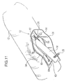
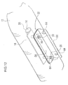
- FIGs. 10 to 12 the structure in which the gas generator 14 and the retainer 16 are arranged in the airbag 12, which has not been shown in Figs. 1 to 6, will be described hereinafter.
- Fig. 10 is an exploded perspective view of the structure in which the gas generator 14 and the retainer 16 are arranged in the airbag 12;
- Fig. 11 is a perspective view of the gas generator 14 and the retainer 16 being inserted into the airbag 12; and
- Fig. 12 is a perspective view of the airbag 12 in which the gas generator 14 and the retainer 16 have been arranged.
- the airbag 12 has a slit (cut) 50 in the lower surface, for the gas generator 14 and the retainer 16 to insert.
- the airbag 12 has two bolt insertion holes 12a in the lower surface, for the two stud bolts 20 projecting from the lower surface of the retainer 16 to pass through. While opposite ends of the slit 50 connect to the bolt insertion holes 12a, the arrangement of the slit 50 is not limited to that.
- the slit 50 may be arranged in a position remote from the bolt insertion holes 12a.
- the width and the length of the slit 50 are set as appropriate depending on the size of the gas generator 14 and the retainer 16.
- the airbag 12 also has a cover cloth 52 on the lower surface, for covering the slit 50 and the bolt insertion holes 12a.
- One half of the cover cloth 52 is a base piece 54 attached to the periphery of the slit 50 and the bolt insertion holes 12a with mounting means such as stitching, while the other half is a cover 56 folded on the base piece 54.
- Numeral 58 in Fig. 11 denotes a seam made of sewing thread or the like that joins the base piece 54 to the lower surface of the airbag 12.
- the base piece 54 has a slit 60 similar to the slit 50 of the airbag 12 and two bolt insertion holes 62 for the stud bolts 20 to pass through, which overlap concentrically with the bolt insertion holes 12a of the airbag 12, respectively. Opposite ends of the slit 60 also connect to the bolt insertion holes 62, respectively.
- the arrangement, however, is not limited to that.
- the slit 60 may be arranged remote from the bolt insertion holes 62, as with the slit 50.
- the width and the length of the slit 60 are also set as appropriate depending on the size of the gas generator 14 and the retainer 16.
- the cover 56 also has two bolt insertion holes 64 for the stud bolts 20 to pass through, which overlap concentrically with the bolt insertion holes 62 of the base piece 54, respectively, when the cover 56 is folded on the base piece 54.
- the cover 56 has not slits such as the slits 50 and 60; when the cover 56 is folded on the base piece 54, the respective slits 60 and 50 of the base piece 54 and the airbag 12 are closed with the cover 56.
- the gas generator 14 and the retainer 16 are disposed inside the airbag 12, first, the gas generator 14 is locked to the bracket 30 of the retainer 16 in advance. Referring to Fig. 11, the retainer 16 with the gas generator 14 is inserted into the airbag 12 through the slits 60 and 50 so as to expand the slit 60 of the base piece 54 of the cover cloth 52 and the slit 50 of the airbag 12.
- the cover 56 of the cover cloth 52 is folded on the base piece 54, in which case the contact surface of the cover 56 and the base piece 54 may be coated with a sealing member or the like.
- the stud bolts 20 are extended from the interior of the airbag 12 to the exterior through the respective bolt insertion holes 12a, 62, and 64 of the airbag 12, the base piece 54, and the cover 56.
- the first nuts 24 are tightened to the stud bolts 20 to join the airbag 12 and the retainer 16 together.
- the ground fabric of the airbag 12 and the base piece 54 and the cover 56 of the cover cloth 52 are clamped by the retainer 16 and the first nuts 24, so that the cover 56 is brought into close contact with the base piece 54 to close the slits 60 and 50. Accordingly, the gas from the gas generator 14 is prevented from flowing to the exterior of the airbag 12 through the slits 50 and 60 when the gas generator 14 is activated.
- An airbag module 10A of Fig. 7 includes a retainer 16A in the airbag 12.
- the retainer 16A is placed on the inner surface of the airbag 12 so as to push the lower part of the airbag 12 from the interior of the airbag 12 against the bottom of the airbag module housing 8d of the seat pan 8.
- the stud bolts 20 project downward from the lower surface of the retainer 16A.
- Each stud bolt 20 is passed through the bolt insertion hole (not shown in Fig. 7) in the lower part of the airbag 12, to which the first nut 24 is tightened from the exterior of the airbag 12 through the patch 22; thus, the airbag 12 is joined to the retainer 16A.
- the embodiment has no recess for accommodating the patches 22 and the first nuts 24 in the bottom of the airbag module housing 8d; instead, it has a recess 28A for accommodating the patches 22 and the first nuts 24 in the lower surface of the retainer 16A.
- Figs. 1 to 6 Other arrangement of the occupant protection system including the airbag module 10A is the same as that of the occupant protection system of Figs. 1 to 6; the same numerals of Fig. 7 as those of Figs. 1 to 6 designate the same components.
- the patches 22 and the first nuts 24 which join the airbag 12 to the retainer 16A are accommodated in the recess 28A in the lower surface of the retainer 16A. Accordingly, when the retainer 16A is arranged in the airbag module housing 8d, the retainer 16A is brought into close contact with the bottom of the airbag module housing 8d through the airbag 12 without the retainer 16A being separated from the bottom of the airbag module housing 8d by the distance corresponding to the thickness of the patches 22 and the first nuts 24.
- an airbag module 10B of Fig. 8 uses a substantially box-shaped gas generator holder 16B as retainer.
- This embodiment includes the gas generator 14 in the gas generator holder 16B.
- the gas generator holder 16B has an open area 16b on the top. A jet of gas from the gas generator 14 is issued upward through the open area 16b.
- the lower surface of the gas generator holder 16B is flat.
- the gas generator holder 16B is disposed in the airbag 12, the lower surface of which is placed on the inner surface of the lower part of the airbag 12.
- the stud bolts 20 project downward from the lower surface of the gas generator holder 16B and extend to the exterior of the airbag 12 through bolt insertion holes (not shown) at the lower part of the airbag 12.
- the first nuts 24 are tightened to the stud bolts 20 through the patch 22, so that the airbag 12 is joined to the gas generator holder 16B.
- the embodiment has the recess 28 in the bottom of the airbag module housing 8d of the seat pan 8, for accommodating the patches 22 and the first nuts 24.
- the width of the recess 28 is smaller than that of the gas generator holder 16B. Accordingly, when the gas generator holder 16B is disposed in the airbag module housing 8d, the patches 22 and the first nuts 24 which project from the lower surface of the gas generator holder 16B are accommodated in the recess 28 and the lower surface of the gas generator holder 16B is brought into close contact with the bottom of the airbag module housing 8d through the airbag 12.
- Other structure of the occupant protection system of Fig. 8 is the same as that of the occupant protection system of Figs. 1 to 6.
- the above-described embodiments use a bag-shaped enclosure that covers the entire folded airbag as the enclosure for covering the airbag so as to restrain the airbag in a folded condition.
- the structure of the enclosure is not limited to that.
- an airbag 12A of an airbag module 10C of Fig. 9(a) includes brackets 40 on the left and right opposite ends for joining the airbag 12A to a seat pan (not shown) and openings 18a on the left and right opposite ends of the enclosure 18A for extending the brackets 40 outwards.
- Numeral 40a denotes an insertion hole for a bolt (not shown) for fixing each bracket 40 to the seat pan.
- An enclosure 18B of an airbag module 10D of Fig. 9(b) is shaped like a tube surrounding the center of the length of the folded airbag 12.
- An enclosure 18C of an airbag module 10E of Fig. 9(c) is shaped like a band wound around the intermediate of the length of the folded airbag 12.
- the displacement of the enclosures can be prevented by arranging them such that the stud bolts projecting from the retainer pass through the enclosures or the enclosures are in contact with the stud bolts.
- the joining of the airbag to the retainer and the fixing of the retainer to the seat pan are made with common stud bolts.
- the stud bolt for joining the airbag to the retainer and the stud bolt for fixing the retainer to the seat pan may be provided separately.
- the means for joining the airbag to the retainer and the means for fixing the retainer to the seat pan are not limited to the stud bolt and the nut.
Abstract
Description
Claims (3)
- An occupant protection system, comprising:wherein the airbag (12) and the gas generator (14) are joined to the seat pan (8) after the airbag (12) and the gas generator (14) have been joined together.an airbag (12) disposed between a seat pan (8) and a seat cushion and inflatable to push the seat cushion from below; anda gas generator (14) disposed in the airbag (12), the airbag (12) and the gas generator (14) being joined to the seat pan (8);
- An occupant protection system according to Claim 1, wherein:a bolt (20) projects from the gas generator (14) or a gas-generator retainer (16; 16A; 16B), the bolt (20) passing through the airbag (12) and the seat pan (8);the airbag (12) and the gas generator (14) are joined together by a first nut (24) being tightened to the bolt (20); andthe airbag (12) and the gas generator (14) are joined to the seat pan (8) by a second nut (26) being tightened to the bolt (20).
- An occupant protection system according to Claim 2, wherein the seat pan (8) has a recess (28) for accommodating the first nut (24).
Applications Claiming Priority (2)
| Application Number | Priority Date | Filing Date | Title |
|---|---|---|---|
| JP2003301607A JP4238675B2 (en) | 2003-08-26 | 2003-08-26 | Crew protection device |
| JP2003301607 | 2003-08-26 |
Publications (3)
| Publication Number | Publication Date |
|---|---|
| EP1510420A2 true EP1510420A2 (en) | 2005-03-02 |
| EP1510420A3 EP1510420A3 (en) | 2005-04-13 |
| EP1510420B1 EP1510420B1 (en) | 2009-02-11 |
Family
ID=34101173
Family Applications (1)
| Application Number | Title | Priority Date | Filing Date |
|---|---|---|---|
| EP04006954A Expired - Fee Related EP1510420B1 (en) | 2003-08-26 | 2004-03-23 | Occupant protection system |
Country Status (5)
| Country | Link |
|---|---|
| US (1) | US7306257B2 (en) |
| EP (1) | EP1510420B1 (en) |
| JP (1) | JP4238675B2 (en) |
| CN (1) | CN100369772C (en) |
| DE (1) | DE602004019365D1 (en) |
Cited By (11)
| Publication number | Priority date | Publication date | Assignee | Title |
|---|---|---|---|---|
| EP1777123A1 (en) * | 2005-10-24 | 2007-04-25 | Takata Corporation | Airbag system |
| EP1829734A3 (en) * | 2006-03-02 | 2008-01-30 | Takata Corporation | Vehicle seat, motor vehicle and airbag module |
| EP1990243A1 (en) * | 2006-03-02 | 2008-11-12 | Takata Corporation | Occupant restraint system |
| US7559605B2 (en) | 2006-03-02 | 2009-07-14 | Takata Corporation | Vehicle seat, motor vehicle, and airbag module |
| US7600784B2 (en) | 2005-10-24 | 2009-10-13 | Takata Corporation | Occupant's leg restraint system |
| US7614649B2 (en) | 2005-10-25 | 2009-11-10 | Takata Corporation | Airbag system |
| US7748730B2 (en) | 2005-11-02 | 2010-07-06 | Takata Corporation | Airbag system |
| US7784865B2 (en) | 2006-03-02 | 2010-08-31 | Takata Corporation | Vehicle seat, motor vehicle, and airbag module |
| WO2019076674A1 (en) * | 2017-10-20 | 2019-04-25 | Dalphi Metal Espana, S.A. | Cover of an airbag for a vehicle occupant restraint system, and method for packing an airbag in a cover |
| CN111344188A (en) * | 2017-11-09 | 2020-06-26 | 提爱思科技股份有限公司 | Side airbag device and method for producing a side airbag device |
| EP3844034A4 (en) * | 2018-08-27 | 2022-06-01 | Autoliv ASP, Inc. | Knee airbag assemblies |
Families Citing this family (45)
| Publication number | Priority date | Publication date | Assignee | Title |
|---|---|---|---|---|
| DE10301462B3 (en) * | 2003-01-16 | 2004-08-05 | Breed Automotive Technology, Inc., Lakeland | Airbag module for automobile has free ends of gas bag bent transverse to its longitudinal direction for providing lugs inserted through gas bag fixing devices |
| JP4269826B2 (en) * | 2003-03-12 | 2009-05-27 | タカタ株式会社 | Crew protection device |
| JP4581812B2 (en) * | 2003-09-30 | 2010-11-17 | タカタ株式会社 | Crew protection device |
| JP2005231505A (en) * | 2004-02-19 | 2005-09-02 | Takata Corp | Occupant crash protection device |
| JP2006240606A (en) * | 2005-02-04 | 2006-09-14 | Takata Corp | Occupant crash protection device |
| EP1721788B1 (en) * | 2005-04-22 | 2011-08-24 | Lisi Automotive Rapid | Fastening element for fastening and restraining an airbag on a vehicle body |
| JP4775111B2 (en) * | 2005-05-25 | 2011-09-21 | タカタ株式会社 | Crew protection device |
| JP2007118687A (en) * | 2005-10-26 | 2007-05-17 | Takata Corp | Occupant restraining gear |
| JP2007118817A (en) * | 2005-10-28 | 2007-05-17 | Takata Corp | Occupant restraining device |
| JP4802660B2 (en) * | 2005-10-28 | 2011-10-26 | タカタ株式会社 | Crew restraint system |
| JP4802659B2 (en) * | 2005-10-28 | 2011-10-26 | タカタ株式会社 | Crew restraint system |
| JP4857713B2 (en) * | 2005-10-28 | 2012-01-18 | タカタ株式会社 | Crew restraint system |
| JP2007131104A (en) * | 2005-11-09 | 2007-05-31 | Takata Corp | Occupant restraining device |
| JP4961902B2 (en) * | 2005-12-01 | 2012-06-27 | 豊田合成株式会社 | Crew protection device |
| US20070132214A1 (en) | 2005-12-01 | 2007-06-14 | Toyoda Gosei Co., Ltd. | Passenger protection device |
| JP4984515B2 (en) * | 2005-12-14 | 2012-07-25 | タカタ株式会社 | Crew restraint system |
| JP4951986B2 (en) * | 2006-02-03 | 2012-06-13 | タカタ株式会社 | Air bag and air bag device |
| JP4878878B2 (en) * | 2006-03-15 | 2012-02-15 | タカタ株式会社 | Vehicle seat, vehicle |
| JP4850563B2 (en) * | 2006-04-05 | 2012-01-11 | タカタ株式会社 | Vehicle seat, vehicle, airbag module |
| JP2007276600A (en) * | 2006-04-05 | 2007-10-25 | Takata Corp | Vehicle seat, vehicle, and airbag module |
| JP2007276598A (en) * | 2006-04-05 | 2007-10-25 | Takata Corp | Vehicular seat, vehicle, and airbag module |
| US7648161B2 (en) * | 2006-04-19 | 2010-01-19 | Honda Motor Co., Ltd. | Airbag device |
| DE202006008373U1 (en) * | 2006-05-19 | 2006-09-14 | Takata-Petri (Ulm) Gmbh | Airbag arrangement in particular for lateral airbag, comprising compression unit to be attached to seat |
| US20080088119A1 (en) * | 2006-10-13 | 2008-04-17 | Yoshiki Murakami | Passenger constraining apparatus |
| JP5034902B2 (en) * | 2007-11-29 | 2012-09-26 | 豊田合成株式会社 | Airbag device |
| JP5463199B2 (en) * | 2010-05-14 | 2014-04-09 | 芦森工業株式会社 | Airbag device |
| JP2012016970A (en) * | 2010-07-06 | 2012-01-26 | Toyota Motor Corp | Vehicular seat built in with cushion airbag device |
| JP5675293B2 (en) * | 2010-11-17 | 2015-02-25 | 芦森工業株式会社 | Vehicle seat equipped with an airbag device |
| DE102011002561B4 (en) * | 2011-01-12 | 2019-01-31 | Lear Corp. | Airbag with one-piece protection element |
| CN103974857B (en) * | 2011-11-29 | 2017-10-27 | 提爱思科技股份有限公司 | Installing component and air bag module equipment seat |
| JP5958129B2 (en) * | 2012-07-12 | 2016-07-27 | 豊田合成株式会社 | Seat cushion airbag device |
| JP5962490B2 (en) * | 2012-12-19 | 2016-08-03 | トヨタ紡織株式会社 | Vehicle seat |
| JP6178155B2 (en) * | 2013-08-02 | 2017-08-09 | テイ・エス テック株式会社 | Seat with air bag module |
| EP2939886B1 (en) | 2012-12-28 | 2018-12-05 | TS Tech Co., Ltd. | Airbag module-equipped seat, and method for mounting same |
| US8746732B1 (en) * | 2013-03-15 | 2014-06-10 | Autoliv Asp, Inc. | Airbag assembly load distributing structure |
| CN105142991B (en) * | 2013-04-24 | 2019-07-05 | Tk控股公司 | Air bag the cover |
| US9616839B2 (en) * | 2014-05-18 | 2017-04-11 | Toyota Motor Engineering & Manufacturing North America, Inc. | H-point referenced seat cushion airbag system |
| US9731634B2 (en) * | 2015-08-28 | 2017-08-15 | Toyoda Gosei Co., Ltd. | Seat cushion airbag apparatus |
| KR102440403B1 (en) * | 2015-09-09 | 2022-09-05 | 현대모비스 주식회사 | Knee air bag apparatus and method for manufacturing of knee air bag apparatus |
| JP6412218B2 (en) * | 2017-07-13 | 2018-10-24 | テイ・エス テック株式会社 | Seat with air bag module |
| US11117539B2 (en) * | 2018-06-26 | 2021-09-14 | Toyoda Gosei Co., Ltd. | Seat device with arresting portion |
| CN108790960A (en) * | 2018-08-03 | 2018-11-13 | 奇瑞商用车(安徽)有限公司 | A kind of automotive seat installation foot decoration cover structure and its installation method |
| US11465580B2 (en) * | 2020-04-08 | 2022-10-11 | Autoliv Asp, Inc. | Bi-directional airbag cushion wrappers and related airbag assemblies and methods |
| US11345302B2 (en) * | 2020-07-27 | 2022-05-31 | ZF Passive Safety Systems US Inc. | Curtain airbag with integral airbag wrap |
| US11247629B1 (en) | 2020-08-17 | 2022-02-15 | Ford Global Technologies, Llc | Vehicle airbag |
Citations (2)
| Publication number | Priority date | Publication date | Assignee | Title |
|---|---|---|---|---|
| US6196577B1 (en) * | 1998-09-18 | 2001-03-06 | Honda Giken Kogyo Kabushiki Kaisha | Air bag apparatus |
| US20010011810A1 (en) * | 1999-12-28 | 2001-08-09 | Ryoji Saiguchi | Passenger protecting apparatus |
Family Cites Families (17)
| Publication number | Priority date | Publication date | Assignee | Title |
|---|---|---|---|---|
| DE2913474A1 (en) * | 1979-04-04 | 1980-10-16 | Daimler Benz Ag | Collision protection for car seat - involves inertial airbag inside seat cushion to prevent occupant sliding out of belt |
| US4918382A (en) * | 1989-03-20 | 1990-04-17 | Tektronix, Inc. | Method for distinguishing between real and spurious responses in a spectrum analyzer |
| JPH05229378A (en) | 1992-02-20 | 1993-09-07 | Toyota Motor Corp | Vehicle seat |
| JP3424421B2 (en) * | 1996-02-02 | 2003-07-07 | 豊田合成株式会社 | Airbags and how to fold them |
| JP3285129B2 (en) * | 1997-01-31 | 2002-05-27 | ジョンソン コントロールズ オートモーティブ システムズ株式会社 | Vehicle seat |
| CN2380444Y (en) * | 1999-02-15 | 2000-05-31 | 姜延兴 | Active safety protection system for driver and passengers of automobile |
| US6604599B2 (en) * | 1999-03-15 | 2003-08-12 | Nhk Spring Co., Ltd. | Anti-submarine vehicle occupant restraint system |
| US6543803B1 (en) * | 1999-07-16 | 2003-04-08 | Ts Tech Co., Ltd. | Air bag apparatus |
| JP2001047961A (en) * | 1999-08-09 | 2001-02-20 | T S Tec Kk | Air bag device |
| JP2002079863A (en) | 2000-09-06 | 2002-03-19 | Toyoda Gosei Co Ltd | Vehicle seat |
| KR100520201B1 (en) * | 2000-09-22 | 2005-10-11 | 오토리브 만도 주식회사 | Passenger air bag |
| JP2002264749A (en) * | 2001-03-07 | 2002-09-18 | Takata Corp | Occupant protector |
| JP2002283900A (en) | 2001-03-28 | 2002-10-03 | Johnson Controls Automotive Systems Corp | Vehicular seat |
| US6669226B2 (en) * | 2002-01-29 | 2003-12-30 | Breed Automotive Technology, Inc. | Air bag module with oppositely aligned inflators |
| JP3972736B2 (en) * | 2002-06-04 | 2007-09-05 | タカタ株式会社 | Crew protection device |
| US20060017266A1 (en) * | 2003-09-30 | 2006-01-26 | Takata Corporation | Passenger protecting device |
| US20070132214A1 (en) * | 2005-12-01 | 2007-06-14 | Toyoda Gosei Co., Ltd. | Passenger protection device |
-
2003
- 2003-08-26 JP JP2003301607A patent/JP4238675B2/en not_active Expired - Fee Related
-
2004
- 2004-03-23 EP EP04006954A patent/EP1510420B1/en not_active Expired - Fee Related
- 2004-03-23 DE DE602004019365T patent/DE602004019365D1/en not_active Expired - Lifetime
- 2004-05-10 US US10/842,232 patent/US7306257B2/en not_active Expired - Fee Related
- 2004-06-29 CN CNB2004100619291A patent/CN100369772C/en not_active Expired - Fee Related
Patent Citations (2)
| Publication number | Priority date | Publication date | Assignee | Title |
|---|---|---|---|---|
| US6196577B1 (en) * | 1998-09-18 | 2001-03-06 | Honda Giken Kogyo Kabushiki Kaisha | Air bag apparatus |
| US20010011810A1 (en) * | 1999-12-28 | 2001-08-09 | Ryoji Saiguchi | Passenger protecting apparatus |
Non-Patent Citations (2)
| Title |
|---|
| PATENT ABSTRACTS OF JAPAN vol. 1998, no. 13, 30 November 1998 (1998-11-30) & JP 10 217818 A (IKEDA BUSSAN CO LTD), 18 August 1998 (1998-08-18) * |
| PATENT ABSTRACTS OF JAPAN vol. 2003, no. 01, 14 January 2003 (2003-01-14) & JP 2002 264749 A (TAKATA CORP), 18 September 2002 (2002-09-18) * |
Cited By (13)
| Publication number | Priority date | Publication date | Assignee | Title |
|---|---|---|---|---|
| US7600784B2 (en) | 2005-10-24 | 2009-10-13 | Takata Corporation | Occupant's leg restraint system |
| EP1777123A1 (en) * | 2005-10-24 | 2007-04-25 | Takata Corporation | Airbag system |
| US7614649B2 (en) | 2005-10-25 | 2009-11-10 | Takata Corporation | Airbag system |
| US7748730B2 (en) | 2005-11-02 | 2010-07-06 | Takata Corporation | Airbag system |
| EP1990243A4 (en) * | 2006-03-02 | 2009-04-29 | Takata Corp | Occupant restraint system |
| US7559605B2 (en) | 2006-03-02 | 2009-07-14 | Takata Corporation | Vehicle seat, motor vehicle, and airbag module |
| EP1990243A1 (en) * | 2006-03-02 | 2008-11-12 | Takata Corporation | Occupant restraint system |
| EP1829734A3 (en) * | 2006-03-02 | 2008-01-30 | Takata Corporation | Vehicle seat, motor vehicle and airbag module |
| US7784865B2 (en) | 2006-03-02 | 2010-08-31 | Takata Corporation | Vehicle seat, motor vehicle, and airbag module |
| WO2019076674A1 (en) * | 2017-10-20 | 2019-04-25 | Dalphi Metal Espana, S.A. | Cover of an airbag for a vehicle occupant restraint system, and method for packing an airbag in a cover |
| CN111344188A (en) * | 2017-11-09 | 2020-06-26 | 提爱思科技股份有限公司 | Side airbag device and method for producing a side airbag device |
| CN111344188B (en) * | 2017-11-09 | 2023-03-10 | 提爱思科技股份有限公司 | Side airbag arrangement and method for producing a side airbag arrangement |
| EP3844034A4 (en) * | 2018-08-27 | 2022-06-01 | Autoliv ASP, Inc. | Knee airbag assemblies |
Also Published As
| Publication number | Publication date |
|---|---|
| DE602004019365D1 (en) | 2009-03-26 |
| EP1510420B1 (en) | 2009-02-11 |
| US20050046156A1 (en) | 2005-03-03 |
| JP2005067465A (en) | 2005-03-17 |
| US7306257B2 (en) | 2007-12-11 |
| JP4238675B2 (en) | 2009-03-18 |
| EP1510420A3 (en) | 2005-04-13 |
| CN100369772C (en) | 2008-02-20 |
| CN1590168A (en) | 2005-03-09 |
Similar Documents
| Publication | Publication Date | Title |
|---|---|---|
| EP1510420B1 (en) | Occupant protection system | |
| US7530597B2 (en) | Airbag device for front passenger's seat | |
| US7185912B2 (en) | Knee protection airbag device | |
| KR100500101B1 (en) | Side airbag curtain module | |
| JP3878220B2 (en) | Airbag device | |
| US7360789B2 (en) | Airbag device for front passenger's seat | |
| US7331602B2 (en) | Head-protecting airbag | |
| JP3459958B2 (en) | Airbag device | |
| US7891700B2 (en) | Airbag for knee protection | |
| EP2987683B1 (en) | Side airbag device | |
| US10632953B2 (en) | Airbag device | |
| EP1422104B1 (en) | Occupant protection system | |
| CN110431052B (en) | Occupant protection device | |
| US7748730B2 (en) | Airbag system | |
| KR19980701381A (en) | Side Impact Soft Pack Airbag Modules (SIDE IMPACT SOFT PACK AIR BAG MODULE) | |
| JP2004106560A (en) | Air bag device for knee protection | |
| WO2007049580A1 (en) | Occupant restraining system | |
| JP2003063351A (en) | Passenger constraint device | |
| WO2019138954A1 (en) | Occupant protection apparatus | |
| US5568936A (en) | Airbag module case for side impact airbag module | |
| JP2007106215A (en) | Occupant restraint system | |
| JP2002166808A (en) | Air bag system | |
| US6196577B1 (en) | Air bag apparatus | |
| JP5455789B2 (en) | Airbag | |
| US7614649B2 (en) | Airbag system |
Legal Events
| Date | Code | Title | Description |
|---|---|---|---|
| PUAI | Public reference made under article 153(3) epc to a published international application that has entered the european phase |
Free format text: ORIGINAL CODE: 0009012 |
|
| PUAL | Search report despatched |
Free format text: ORIGINAL CODE: 0009013 |
|
| AK | Designated contracting states |
Kind code of ref document: A2 Designated state(s): AT BE BG CH CY CZ DE DK EE ES FI FR GB GR HU IE IT LI LU MC NL PL PT RO SE SI SK TR |
|
| AX | Request for extension of the european patent |
Extension state: AL LT LV MK |
|
| AK | Designated contracting states |
Kind code of ref document: A3 Designated state(s): AT BE BG CH CY CZ DE DK EE ES FI FR GB GR HU IE IT LI LU MC NL PL PT RO SE SI SK TR |
|
| AX | Request for extension of the european patent |
Extension state: AL LT LV MK |
|
| 17P | Request for examination filed |
Effective date: 20050906 |
|
| AKX | Designation fees paid |
Designated state(s): DE FR GB SE |
|
| GRAP | Despatch of communication of intention to grant a patent |
Free format text: ORIGINAL CODE: EPIDOSNIGR1 |
|
| GRAS | Grant fee paid |
Free format text: ORIGINAL CODE: EPIDOSNIGR3 |
|
| GRAA | (expected) grant |
Free format text: ORIGINAL CODE: 0009210 |
|
| AK | Designated contracting states |
Kind code of ref document: B1 Designated state(s): DE FR GB SE |
|
| REG | Reference to a national code |
Ref country code: GB Ref legal event code: FG4D |
|
| REF | Corresponds to: |
Ref document number: 602004019365 Country of ref document: DE Date of ref document: 20090326 Kind code of ref document: P |
|
| PG25 | Lapsed in a contracting state [announced via postgrant information from national office to epo] |
Ref country code: SE Free format text: LAPSE BECAUSE OF FAILURE TO SUBMIT A TRANSLATION OF THE DESCRIPTION OR TO PAY THE FEE WITHIN THE PRESCRIBED TIME-LIMIT Effective date: 20090511 |
|
| PLBE | No opposition filed within time limit |
Free format text: ORIGINAL CODE: 0009261 |
|
| STAA | Information on the status of an ep patent application or granted ep patent |
Free format text: STATUS: NO OPPOSITION FILED WITHIN TIME LIMIT |
|
| REG | Reference to a national code |
Ref country code: FR Ref legal event code: ST Effective date: 20091130 |
|
| 26N | No opposition filed |
Effective date: 20091112 |
|
| PG25 | Lapsed in a contracting state [announced via postgrant information from national office to epo] |
Ref country code: FR Free format text: LAPSE BECAUSE OF NON-PAYMENT OF DUE FEES Effective date: 20091123 |
|
| PGFP | Annual fee paid to national office [announced via postgrant information from national office to epo] |
Ref country code: GB Payment date: 20130320 Year of fee payment: 10 |
|
| PGFP | Annual fee paid to national office [announced via postgrant information from national office to epo] |
Ref country code: DE Payment date: 20140417 Year of fee payment: 11 |
|
| GBPC | Gb: european patent ceased through non-payment of renewal fee |
Effective date: 20140323 |
|
| PG25 | Lapsed in a contracting state [announced via postgrant information from national office to epo] |
Ref country code: GB Free format text: LAPSE BECAUSE OF NON-PAYMENT OF DUE FEES Effective date: 20140323 |
|
| REG | Reference to a national code |
Ref country code: DE Ref legal event code: R119 Ref document number: 602004019365 Country of ref document: DE |
|
| PG25 | Lapsed in a contracting state [announced via postgrant information from national office to epo] |
Ref country code: DE Free format text: LAPSE BECAUSE OF NON-PAYMENT OF DUE FEES Effective date: 20151001 |