EP1510312A2 - Verfahren und Vorrichtung zur Herstellung eines dekorierten Formkörpers, und Formkörper mit diesem Verfahren dekoriert - Google Patents
Verfahren und Vorrichtung zur Herstellung eines dekorierten Formkörpers, und Formkörper mit diesem Verfahren dekoriert Download PDFInfo
- Publication number
- EP1510312A2 EP1510312A2 EP04018766A EP04018766A EP1510312A2 EP 1510312 A2 EP1510312 A2 EP 1510312A2 EP 04018766 A EP04018766 A EP 04018766A EP 04018766 A EP04018766 A EP 04018766A EP 1510312 A2 EP1510312 A2 EP 1510312A2
- Authority
- EP
- European Patent Office
- Prior art keywords
- product
- listel
- visible surface
- decorating
- opposite
- Prior art date
- Legal status (The legal status is an assumption and is not a legal conclusion. Google has not performed a legal analysis and makes no representation as to the accuracy of the status listed.)
- Withdrawn
Links
- 238000000034 method Methods 0.000 title claims abstract description 26
- 238000004519 manufacturing process Methods 0.000 title description 14
- 239000000463 material Substances 0.000 claims description 33
- 239000002131 composite material Substances 0.000 claims description 22
- 238000005520 cutting process Methods 0.000 claims description 16
- 238000003825 pressing Methods 0.000 claims description 13
- 229910010293 ceramic material Inorganic materials 0.000 claims description 8
- 238000007493 shaping process Methods 0.000 claims description 4
- 238000011144 upstream manufacturing Methods 0.000 claims description 3
- 238000004026 adhesive bonding Methods 0.000 claims 1
- 239000000919 ceramic Substances 0.000 description 73
- 238000003801 milling Methods 0.000 description 21
- 230000000284 resting effect Effects 0.000 description 18
- 238000000227 grinding Methods 0.000 description 15
- 230000000694 effects Effects 0.000 description 11
- 238000009434 installation Methods 0.000 description 10
- 238000007373 indentation Methods 0.000 description 8
- 238000005253 cladding Methods 0.000 description 5
- 239000000853 adhesive Substances 0.000 description 4
- 230000001070 adhesive effect Effects 0.000 description 4
- 238000000926 separation method Methods 0.000 description 4
- 238000012545 processing Methods 0.000 description 3
- 238000013519 translation Methods 0.000 description 3
- 239000000843 powder Substances 0.000 description 2
- 208000035874 Excoriation Diseases 0.000 description 1
- 238000005299 abrasion Methods 0.000 description 1
- 239000004566 building material Substances 0.000 description 1
- 238000010304 firing Methods 0.000 description 1
- 238000011031 large-scale manufacturing process Methods 0.000 description 1
- 238000012423 maintenance Methods 0.000 description 1
- 238000012986 modification Methods 0.000 description 1
- 230000004048 modification Effects 0.000 description 1
- 230000002028 premature Effects 0.000 description 1
- 230000000750 progressive effect Effects 0.000 description 1
- 238000005096 rolling process Methods 0.000 description 1
Images


Classifications
-
- B—PERFORMING OPERATIONS; TRANSPORTING
- B28—WORKING CEMENT, CLAY, OR STONE
- B28B—SHAPING CLAY OR OTHER CERAMIC COMPOSITIONS; SHAPING SLAG; SHAPING MIXTURES CONTAINING CEMENTITIOUS MATERIAL, e.g. PLASTER
- B28B7/00—Moulds; Cores; Mandrels
- B28B7/16—Moulds for making shaped articles with cavities or holes open to the surface, e.g. with blind holes
- B28B7/164—Moulds for making shaped articles with cavities or holes open to the surface, e.g. with blind holes for plates, panels, or similar sheet- or disc-shaped articles
-
- B—PERFORMING OPERATIONS; TRANSPORTING
- B28—WORKING CEMENT, CLAY, OR STONE
- B28B—SHAPING CLAY OR OTHER CERAMIC COMPOSITIONS; SHAPING SLAG; SHAPING MIXTURES CONTAINING CEMENTITIOUS MATERIAL, e.g. PLASTER
- B28B11/00—Apparatus or processes for treating or working the shaped or preshaped articles
- B28B11/12—Apparatus or processes for treating or working the shaped or preshaped articles for removing parts of the articles by cutting
-
- B—PERFORMING OPERATIONS; TRANSPORTING
- B28—WORKING CEMENT, CLAY, OR STONE
- B28D—WORKING STONE OR STONE-LIKE MATERIALS
- B28D1/00—Working stone or stone-like materials, e.g. brick, concrete or glass, not provided for elsewhere; Machines, devices, tools therefor
- B28D1/30—Working stone or stone-like materials, e.g. brick, concrete or glass, not provided for elsewhere; Machines, devices, tools therefor to form contours, i.e. curved surfaces, irrespective of the method of working used
-
- B—PERFORMING OPERATIONS; TRANSPORTING
- B44—DECORATIVE ARTS
- B44C—PRODUCING DECORATIVE EFFECTS; MOSAICS; TARSIA WORK; PAPERHANGING
- B44C1/00—Processes, not specifically provided for elsewhere, for producing decorative surface effects
- B44C1/22—Removing surface-material, e.g. by engraving, by etching
-
- B—PERFORMING OPERATIONS; TRANSPORTING
- B44—DECORATIVE ARTS
- B44C—PRODUCING DECORATIVE EFFECTS; MOSAICS; TARSIA WORK; PAPERHANGING
- B44C5/00—Processes for producing special ornamental bodies
Definitions
- This invention relates to an apparatus and a method for obtaining a product, in particular a product intended for the installation of finishes of building products in general; also a new product being included within the scope of the present invention.
- the through openings can be obtained by removing from the already formed support a certain quantity of material that makes it up initially.
- This removing operation can be achieved by computer controlled water-jet cutting machines advancing continuously to perform the cutting operation along the corresponding perimeter of the opening that is to be defined.
- Such machines have to be programmed afresh to change over from the creation of openings having a preset shape to the creation of openings having different shapes.
- a not insignificant time is also required for programming the cutting machines whenever one wishes to change the shape of the openings to be obtained on the ceramic products.
- a further drawback is that the cutting machines are programmed to obtain openings of different shapes without taking into account any variations in the thickness of the ceramic products, due for example to the presence of bas-relief on the surface thereof.
- the openings are obtained directly during the phase of forming the support.
- moulds are used that are provided with cores fixed to the base of the mould cooperating with punches that have holes corresponding to the section of the cores and are shaped according to the particular shape of the openings to be made.
- One drawback of the system disclosed above is that it requires dedicated moulds that must be built on demand and that must to be replaced whenever one wishes to modify the number and/or the shape and/or the position of the openings provided on a given product.
- One object of the invention is to simplify the methods and the apparatuses for obtaining products.
- a further object is to supply an apparatus and a method for obtaining products that may be used independently of the particular configuration of the products that one wishes to obtain.
- Yet another object is to supply products that are provided with openings made with great precision whilst keeping cost very moderate.
- a method comprising forming a product, providing cavity means extending to the inside of said product and defining on an intended visible surface a contour of an opening, characterized in that it further comprises subsequently providing further cavity means extending from a surface opposite said intended visible surface for such a depth that a bottom part of said cavity means is removed.
- said cavity means is shaped like an indentation that delimits the perimeter of a rusticated element having any desired shape.
- an apparatus comprising removing means arranged for making an opening in a product provided with cavity means extending from an intended visible surface of said product, characterized in that said removing means is configured in such a way as to remove a part of said product from a surface opposite said intended visible surface until a bottom portion of said cavity means is removed.
- said removing means enables a portion of said product to be removed having a length approximately corresponding to the length of said product.
- said removing means enables a portion of said product to be removed having a width less than or also approximately corresponding to the width of said product.
- a product comprising cavity means extending to the inside of body means of said product starting from its own intended visible surfaces and defining on said intended visible surface a contour of an opening, characterized in that it further comprises further cavity means having a greater extent than said cavity means and extending from a surface opposite said intended visible surface for such a depth that said cavity means is lacking in its own bottom portion.
- said cavity means is delimited by edge means having at least one portion that is tilted in relation to said intended visible surface.
- the further cavity means can have a preset shape, for example rectangular or square, completely independently of the shape of the openings, particularly when the latter have tilted edges.
- the further cavity means may have an extent equal to a longitudinal and/or transversal dimension of said products.
- a composite element comprising product means provided with a plurality of opening means and decorating means associated with said product means and comprising a plurality of protruding means shaped in such a way as to be shapingly coupled with said opening means.
- this decorating element has significantly larger dimensions than the single tesseras
- handling operations are further simplified, furthermore, as the dimensions of the decorating element do not depend on the dimensions of the openings of the product means, it is possible to create openings with dimensions that are even very small without being consequently forced to use tesseras of the corresponding dimensions.
- Figures 1 to 12 and 23 to 55 show different embodiments of a ceramic listel 1 obtained by forming, for example by pressing ceramic material in powder form.
- the ceramic listel 1 is provided with a body 21 having a visible surface 2, resting portions 3 to enable the ceramic listel 1 to be rested on a desired resting surface 4, a not visible surface 6, a thickness 5, an end portion 22 and a further end portion 23.
- the visible surface 2 of the ceramic listel 1 is configured in such a way as to comprise at least one recessed portion 7 extending into the thickness of the ceramic listel 1 towards the not visible surface 6 thereof.
- Such recessed portion 7 comprises side edges 9, an external edge 10 and a bottom surface 8 corresponding to the zone of maximum depth of the recessed portion 7 in relation to the visible surface 2 of the ceramic listel 1.
- the bottom surface 8 is located at a distance D1 from the visible surface 2, and at a further distance D2 from the not visible surface 6.
- recessed portions 7 On the visible surface 2, can be obtained a desired number of recessed portions 7 that can have differing shapes one with to other and are delimited by side edges 9 and by external edges 10 of any shape, for example of curved shape.
- the recessed portions 7 extend on the visible surface 2 of the ceramic listel 1 in such a way as to be contained in said visible surface 2, in particular in such a way as to be distanced from the end portion 22 and from the further end portion 23 of the ceramic listel 1 by corresponding edge zones 24.
- the side edges 9 may be substantially perpendicular to the bottom surface 8, or they may comprise a first segment 9a, nearer the visible surface 2, which is tilted in relation to the not visible surface 6, and a second segment 9b, further away from the visible surface 2, that is substantially perpendicular to the not visible surface 6.
- the presence of the second segment 9b enables openings 13 to be obtained that have defined contours, namely contours lacking in burrs or in ragged zones.
- the second segment 9b furthermore enables to prevent that possible shifts in a vertical direction in relation to the ceramic listel 1 of abrading means, disclosed in greater detail below, generate irregularities in the edge zones of the obtained openings.
- the second segment 9b has a thickness that is not less than 1,5 mm.
- the ceramic listel 1 is obtained as previously disclosed, i.e. provided with the recessed portions 7, it is subjected to a milling operation - carried out by the abrading means - by means of which a volume of ceramic material is removed from the part of the not visible surface 6.
- a space is defined having a rectangular section 12 - indicated by a broken line in Figure 2 - and a greater extent than the recessed portions 7.
- This space has a substantially regular shape, in particular a parallelepiped shape, which significantly simplifies the milling operation inasmuch as space with a simple shape are easier to make.
- This space has a length that is the same as the length L of the ceramic listel 1, so as to extend from the end portion 22 to the further end portion 23 of the body 21 of the ceramic listel 1, and a thickness that is approximately the same as the distance D2 between the bottom surface 8 of the recessed portions 7 and the not visible surface 6.
- the listel 1 appears as shown in Figure 3, i.e. it is provided on its not visible surface 6, with a through channel 26, i.e. a channel extending along the entire length L of the ceramic listel 1.
- the listel 1 is furthermore provided, on a zone of its visible surface 2 corresponding to the bottom surface 8 of the recessed portions 7, with openings 13 that are obtained in consequence of the milling operation and that are delimited by the side edges 9 of the recessed portions 7.
- the number and/or the shape of the openings 13 depend respectively on the number and/or the shape of the recessed portions 7 that were previously obtained in the ceramic listel 1.
- the openings 13 are configured in such a way that when a decorating element 14 is associated to the listel 1, for example in the manner shown in Figure 4, an upper portion 15 of the decorating element 14 is visible through the openings 13 on the visible surface 2 of the ceramic listel 1.
- the decorating element 14 may have a thickness S2 such that one of its bottom surfaces 44 is coplanar with the resting portions 3, so as to form with the latter a resting base 20A of a composite product 20 formed by associating the decorating element 14 with the Listel 1.
- listel 1 arranged for being installed in such a way as to be adjacent to a cladding made of ceramic products, for example tiles 31.
- listel 1 constitutes a finishing element of the cladding of a building product, for example a wall.
- the tiles 31 have a thickness S1 that is the same as the thickness S2 of the decorating element 14.
- the decorating element 14 can be obtained by cutting a tile 31 so as to obtain a tessera having dimensions that are such as to be able to be received inside the through channel 26.
- the presence of the net 18 enables transport and installation of the composite product 20 to be facilitated and furthermore enables the stability thereof to be increased, preventing, for example, mutual shifts between the listel 1 and the decorating element 14.
- a further decorating element 140 having a thickness that is less than the distance between the bottom surface 8 and the resting portions 3 can be associated with the ceramic listel 1.
- Adhesive materials are used in this case in order to ensure stable cohesion between the further decorating element 140 and the ceramic listel 1.
- the further decorating element 140 is connected to the ceramic listel 1 by limited amounts 141 of the adhesive materials.
- the listel has considerable dimensions and/or the recessed portion has a very limited extent in relation to that of the listel, there is provided to remove a quantity of ceramic material from the part of the not visible surface of the ceramic listel so as to create a space having dimensions that are only slightly greater than those of the recessed portion, said space does not extend along the entire length L of the listel 1.
- This space has a rectangular or anyway regular section such as to be able to receive a ceramic listel having a desired shape.
- the space has a longitudinal dimension that is less than the length L of the listel 1.
- listel 1 shown in Figures 7 to 9
- the parts corresponding to the listel 1 in Figures 1 to 5 are indicated by the same numerical references.
- the listel 1 is shown in Figure 7 after being subjected to a milling operation similar to the one previously disclosed and that is such to remove also in this case from the listel 1 a volume of material such as to define a channel 26 extending along the entire length L of the listel 1.
- the ceramic listel 1 On the visible surface 2 of the ceramic listel 1 is identified at least one opening 13 configured in such a way as to enable a yet further decorating element 14A to be inserted inside it, as shown in Figures 8 and 9.
- the yet further decorating element 14A has functions that are similar to the decorating element 14 and to the further decorating element 140 but is shaped in such a way as to be associatable in a shapingly coupled manner with the openings 13 into which it has to be inserted.
- the yet further decorating element 14A has a thickness 5A that is substantially the same as the thickness 5 of the listel 1.
- the yet further decorating element 14A is configured in such a way that its bottom surface 25 is placed at the same vertical level as the resting portions 3, in such a way as to constitute with the latter a resting base 20A of the composite product 20.
- the ceramic listel 1 is shown in Figure 23 and 24 in an intermediate processing stage, namely at the end of the forming phase.
- Each recessed portion 7 made on the visible surface 2 of the ceramic listel 1 is shaped as an indentation 32 that extends through the thickness of the ceramic listel 1 towards the not visible surface 6 thereof and runs on the side of the visible surface 2 in such a way as to define a preferably closed path, having any desired shape, said path identifies an external perimeter 33 of a portion of the listel 1 shaped as a rusticated element 34 having a thickness 34A that approximately corresponds to the thickness 5 of the listel 1, and shaped for example such as a rhombus.
- the indentation 32 is defined by a bottom surface 8 located at a distance D1 from the visible surface 2, and at a further distance D2 from the not visible surface 6, and by edges 9.
- the presence of the rusticated element 34 of thickness 34A inside the perimeter 33 enables a listel 1 to be obtained that has great dimensional stability during the firing phase.
- Such a volume of material has a thickness that is at least equal to the distance D2 between the bottom surface 8 of the indentations 32 and the not visible surface 6 in such a way that, after the volume of material has been removed, the separation of the rusticated element 34 from the listel 1 is obtained, and through openings 13 delimited by the contour of the indentations 32 are obtained.
- a cut is made along a cutting plane T, indicated with a broken line, thus separating from the listel 1 a volume of material, indicated by cross-hatching in Figure 25, of a width that is the same as the width L1 of the listel 1 and obtaining the listel 1' of Figure 26, namely provided with a plurality of through openings 13 the shape and number of which depend on the number and shape of the indentations 32 that have been made in the listel 1 and having a new bottom surface 35 approximately corresponding to the plane T along which the cut is made.
- the listel 1' may at this point be associated with different types of decorating elements and in different ways, for example in the ways shown in Figures 27 to 33, to obtain a composite element 20 with a desired decorative effect, in which an upper surface 60A of the decorating elements is at least partially visible through the openings 13.
- the listel 1' is associated with a first decorating element 50 having a width the same as the width L1 of the listel 1, in such a way that the new bottom surface 35 of the listel 1 rests on a top surface portion 36 of the first decorating element 50.
- first decorating element 50 an usual ceramic product can be used, such as a tile, or a slab of building material cut to the dimensions of the space made in the listel 1.
- the listel 1' is associated, in a manner completely similar to what has been seen with reference to Figure 27, with a second decorating element 51 provided with portions 52 shaped to be coupled in a shapingly coupled manner with the openings 13, in such a way that after the installation these portions 52 are inserted inside the openings 13.
- the portions 52 may have a variously configured upper surface 60A, for example at least partially protruding towards the exterior in relation to the visible surface 2 of the listel 1.
- the listel 1' tesseras 54 may be further associated that are inserted into the openings 13, as shown for example in Figures 29-31.
- Such tesseras 54 may have a variously configured upper surface and may be positioned in such a way that their bottom surfaces 55 is approximately coplanar with the new bottom surface 35 of the listel 1' and cooperates with the latter to define the resting base 20A of the composite element 20 ( Figures 29, 30).
- the tesseras 54 can also be positioned in such a way that the new bottom surface 35 of the listel 1' is positioned after installation at a different height in relation to the bottom surface 55 of the tesseras 54, in such a case that it is necessary to appropriately fix the tesseras 54 to the listel 1' to prevent movements of the latter in relation to the tesseras 54, for example in one of the ways seen previously.
- the thickness of the decorating elements 50, 51, and/or the tesseras 54, and/or the listel 1 can be varied in such a way as to create a composite element 20 that generates a particular desired effect of alternating relief or jutties in relation to the tiles 31 next to which the composite element 20 is installed, in particular such a thickness may be less or the same as the thickness S1 of the tiles 31.
- tesseras 54 can be inserted in the openings 13 of the listel 1'', in a manner that is completely similar to what has been seen with reference to Figures 29-31, such tesseras 54 having variously configured upper surfaces 60A, namely such as to be substantially coplanar with the visible surface 2 of the listel 1'' ( Figure 36), or at least partially protruding from the visible surface 2 of the listel 1'' ( Figure 37), and a bottom surface 55 that in installation may be coplanar with the resting portions 3 of the listel 1.
- listel 1'' may be associated, with reference to Figures 389 and 39, with a third decorating element 56 in such a way that the resting portions 3A and 3B of the listel 1'' rest on surface portions 56A of the third decorating element 56 and a bottom surface 56B of the third decorating element 56 constitutes the resting base 20A of the obtained composite element 20.
- the thickness of the third decorating element 56 may be such that the resting surface 3 of the listel 1'' is positioned in installation at a different height from that of the resting base 20A of the composite element 20, furthermore the upper surface 60A of the third decorating element 56 may be flat and substantially coplanar with the visible surface 2 of the listel 1'' ( Figure 38), or may be positioned at a different height in relation with the latter ( Figure 39), or may be provided with protrusions that during installation are inserted into the openings 13 of the listel 1'' and possibly at least partially protruding from the visible surface 2 of the listel 1''.
- FIGs 40 to 45 a further embodiment of ceramic listel 1 is shown that is similar to the one shown in Figures 23 to 33, and differs therefrom substantially in the different path of the indentations 32 that identify a rusticated element 34 with a curved shape.
- This ceramic listel 1 may be subjected to the same milling operations seen for the ceramic listel in Figures 23-24, in particular, from the ceramic listel a volume of material can be removed with the same width as the width L1 of the listel 1 ( Figure 42), or with a width less than the width L1 of the listel 1 ( Figure 43).
- the listel obtained after any of the above milling operations can then be associated with any decorating element, shaped for example in any of the previously seen ways, obtaining each time composite elements 20 having decorative effect that are different from one another.
- the listel 1 of the invention may have a desired extent, for example listels 100 may be made that have a width that is the same as a desired multiple of the width L1 of the listel 1 in such a way that the listels 100 give the impression of a desired number of listels 1 placed side by side, and the indentations 32 made therein may have a desired reciprocal spatial arrangement, for example, as shown in the two embodiments in Figures 46-47 and 48-55 the listel 100 may have width L3 that is twice the width L1, with a symmetry axis W that ideally identifies two distinct listels 1 of width L1.
- listel 100 may be subjected to milling operations completely similar to those seen previously that are partially discussed below with reference to the embodiment in Figure 48.
- a desired volume of material can be removed to obtain a plurality of through openings 13 in the Listel 1.
- a cut can be made along a cutting plane T indicated with a broken line thus separating from the listel 100 the volume of material indicated by the cross-hatching in Figure 50 that has a width that is the same as the width L3 of the listel in Figure 48.
- a generic listel 100 has width that is the same as a desired multiple of the width of a single listel and is so configured as to result virtually obtained by placing side by side a plurality of ceramic listels, after the aforesaid removing operation a plurality of ceramic listels of the kind of those examined up to here is obtained starting from a sole listel 100.
- the listel 100 can be associated with a building element 60 provided with rusticated elements 61 shaped in such a way as to be inserted into the openings 13.
- the listel 100 can be subjected to a milling operation that enables the portions of material indicated with the cross-hatching in Figure 53 to be separated from the listel 100 and thereby obtaining the listel 100'' in Figure 54; following to a further cutting operation along the axis W in Figure 53, the listel 100''' of Figure 55 is obtained.
- the listel 100" and the listel 100''' can be both associated with decorating elements having various shapes and dimensions, for example in one of the previously shown ways.
- the configuration of the listel 100 in Figures 46-55 enables, after associating a desired decorating element with the listel 100, decorative effects to be obtained that are even more different from those previously seen.
- the dimensions of the space that is created in the listel 100 after the above seen removing operation enables further simplifying and further speeding up the operations of association of the decorating elements with the listel 1 and installation of the obtained composite element 20 obtained, as listels and decorating elements are handled having dimensions that are significant and completely comparable with those of tiles or other cladding materials alongside which the composite elements are placed.
- an apparatus 200 to make in the listels 1 the channel 26 by removing therefrom by a milling operation a preset volume of material adjacent to the not visible surface 6.
- the apparatus 200 comprises flexible conveying means 203 wrapped in a loop around rolling bodies 201 rotating around a rotation axis X in the direction indicated by the arrow F1 and arranged in such a way as to move a train 210 of listels 1 in an advancing direction F.
- the listels 1 of the train 210 of listels are arranged on the flexible conveying means 203 in such a way that the not visible surface 6 of the listels 1 is turned towards an upper surface 209 of the flexible conveying means 203.
- pressing means 205 is provided arranged to exert pressure in the direction indicated by P so as to press the listels 1 against the flexible conveying means 203, in particular during the milling operation.
- the apparatus 200 is provided with abrading means comprising a grinding wheel 204 that is rotatable about a further axis Y in the rotation direction F1 and movable in the direction of the arrow F3 away from and towards the listels 1, in such a way as to make on the side of the not visible surface 6 of the listels 1, channels 26 having a desired depth.
- abrading means comprising a grinding wheel 204 that is rotatable about a further axis Y in the rotation direction F1 and movable in the direction of the arrow F3 away from and towards the listels 1, in such a way as to make on the side of the not visible surface 6 of the listels 1, channels 26 having a desired depth.
- the grinding wheel 204 is positioned in such a way as to be able to interact with each listel 1 in such a way that when the listel 1 travels over an active part 206 of the grinding wheel 204 a through channel 26 is made therein, such a channel 26 being provided with an opening turned towards the flexible conveying means 203.
- the pressing means 205 exerts a pressure of a preset amount on the listels 1.
- the rotation direction of the grinding wheel 204 and that of the drive rollers 201 may be consistent between themselves as in the case shown in Figure 15, or be unconsistent.
- the flexible conveying means 203 is supported rigidly, at least at the zone thereof on which the train 210 of listels 1 is positioned, in such a way as to enable milling at a constant depth.
- the grinding wheel 204 that was disclosed above is suitable for removing limited quantities of material from the listels.
- the active part 206 of the grinding wheel is dimensioned according to the width of the space that one wishes to make in the listel 1. If the listels 1 are made in hard and fragile materials, are used abrasive belts 27 ( Figure 13) closed in a loop and tensioned between a return roller and a drive roller, the latter being arranged to rotationally actuate them.
- the abrading means may comprise a plurality of abrading elements arranged on the apparatus 200 in longitudinally consecutive positions.
- the abrading elements are positioned at different vertical heights in order to carry out progressive abrasion of the material.
- each abrading element is positioned can be adjusted by appropriate adjusting means in the direction indicated by the arrow F3.
- FIG 17 there is shown one embodiment of the apparatus 200 in which the grinding wheel 204 is provided with a translation movement in a horizontal and vertical direction in relation to a further train 301 of listels 1, in such a way as to be able to perform the milling action.
- the further train 301 of listels 1 is in this case placed on a work surface 302 after the forming phase in such a way that the visible surface 2 of each listel 1 is in contact with a further upper surface 304 of the work surface 302.
- the work surface 302 may comprise a conveying surface for conveying the listels 1 provided with translation movement in a conveying direction of the listels 1, or may comprise a fixed surface on which the further train 301 of listels 1 to be subjected to the milling action is cyclically loaded.
- the grinding wheel 204 and the work surface 302 are moved in opposite directions to one another so as to reduce the time required for milling the listels 1.
- the grinding wheel 204 is translated in the yet further direction indicated by the arrow F7, from a position A in which the grinding wheel 204 is arranged in an end zone 308 of the work surface 302, to a further position B, in which the grinding wheel 204 is arranged in a further end zone 307 of the work surface 302 opposite the end zone 308.
- the grinding wheel 204 is moved away from the work surface 302 and it is returned to the position A.
- a listel 1 is shown that after the forming phase is completely similar to the ceramic listel shown in Figure 1, in which, starting from the not visible surface 6, a pair of grooves 11 is made that is obtained by a tool, for example a rotating disc 16.
- the grooves are arranged to enable sides 19 ( Figure 13) of the aforesaid abrading means not to interfere during milling operations with portions of material with which the listel 1 is made.
- the abrading means consists of abrasive belts 27.
- the abrasive belts 27 are in fact unable to work on the sides 19 inasmuch as the latter are damaged by the contact with portions of the material that forms up the listels 1.
- the rotating disc 16 is positioned upstream of the abrading means in such a way as to make the grooves 11 in the listels 1.
- the grooves 11 define cavities inside which the sides 19 are received, which are thus preserved from premature wear.
- the presence of the grooves 11 thus enables the productivity of the apparatus 200 to be increased, drastically reducing the need for maintenance or replacement of the abrading means.
- Figure 12 furthermore shows that the listel 1 has a substantially constant thickness even in shaped zones 28 obtained at opposite ends thereof.
- the uniform thickness enables, in cases in which the listels are obtained by pressing, substantially constant density to be obtained at all points of the ceramic listels. This enables dimensional lack of uniformity between listels of the same type to be avoided.
- listel 1 provided on its not visible surface 6 with a pair of hollows 29 having the same function as the above-disclosed grooves 11.
- the hollows 29 are not made by tools but are obtained during forming of the listel 1.
- listel 1 provided on its not visible surface 6 with a pair of throats 30 performing the same function as the grooves 11 and the hollows 29 disclosed above.
- the throats 30 are obtained during forming of the listel 1.
- the grooves 11, the hollows 29 and the throats 30 have a greater depth S than the further distance D2 identified between the bottom surface 8 and the not visible surface 6.
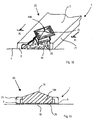
- Figures 18 to 22 show subsequent phases of a production cycle of a composite product according to the invention made by associating a listel 1 with a decorating element 14.
- FIG 18 there is shown a listel 1 obtained by forming, for example by pressing ceramic powders.
- Figure 19 there is shown with cross-hatching a volume of material that has to be removed from the ceramic listel 1.
- Figure 20 shows grooves 11 made by a disc tool in the not visible surface 6 of the listel 1.
- the grooves 11 enables the sides 19 of abrading means arranged for removing the afore said volume not to interfere with the material that forms the listel 1.
- Figure 21 shows the listel 1 after the volume of material has been removed.
- Figure 22 shows the decorating element 14 fixed to the listel 1 by appropriate amounts 141 of adhesive material that are interposed between the listel 1 and the decorating element 14.
- the phase of the processing cycle during which the grooves 11 are made can be eliminated if, as shown in Figures 12 and 13 disclosed above, the listel 1 is provided with hollows 29, or throats 30 made during forming.
Landscapes
- Engineering & Computer Science (AREA)
- Mechanical Engineering (AREA)
- Chemical & Material Sciences (AREA)
- Ceramic Engineering (AREA)
- Manufacturing & Machinery (AREA)
- Structural Engineering (AREA)
- Mining & Mineral Resources (AREA)
- Moulds For Moulding Plastics Or The Like (AREA)
- Devices For Post-Treatments, Processing, Supply, Discharge, And Other Processes (AREA)
Applications Claiming Priority (2)
| Application Number | Priority Date | Filing Date | Title |
|---|---|---|---|
| ITMO20030231 | 2003-08-07 | ||
| IT000231A ITMO20030231A1 (it) | 2003-08-07 | 2003-08-07 | Apparato e metodo per fabbricare un manufatto decoratore e manufatto decoratore |
Publications (2)
| Publication Number | Publication Date |
|---|---|
| EP1510312A2 true EP1510312A2 (de) | 2005-03-02 |
| EP1510312A3 EP1510312A3 (de) | 2006-04-19 |
Family
ID=30012831
Family Applications (1)
| Application Number | Title | Priority Date | Filing Date |
|---|---|---|---|
| EP04018766A Withdrawn EP1510312A3 (de) | 2003-08-07 | 2004-08-06 | Verfahren und Vorrichtung zur Herstellung eines dekorierten Formkörpers, und Formkörper mit diesem Verfahren dekoriert |
Country Status (2)
| Country | Link |
|---|---|
| EP (1) | EP1510312A3 (de) |
| IT (1) | ITMO20030231A1 (de) |
Cited By (4)
| Publication number | Priority date | Publication date | Assignee | Title |
|---|---|---|---|---|
| ITMO20080233A1 (it) * | 2008-09-15 | 2010-03-15 | Siti B & T Group S P A | Metodo ed apparato per realizzare incavi su superfici di manufatti ceramici |
| ITMO20090112A1 (it) * | 2009-05-04 | 2010-11-05 | Itiemm S R L | Metodo per fabbricare un manufatto decoratore |
| ITRE20090065A1 (it) * | 2009-06-24 | 2010-12-25 | Techlever Egineering S R L | Metodo ed apparato per realizzare incavi su superfici di manufatti ceramici |
| CN102094505A (zh) * | 2010-12-31 | 2011-06-15 | 铁岭市石美石材有限公司 | 一种高光泽度复合石材板的制作方法 |
Family Cites Families (4)
| Publication number | Priority date | Publication date | Assignee | Title |
|---|---|---|---|---|
| US4254077A (en) * | 1979-09-10 | 1981-03-03 | Fontana John D | Method for making decorative inlaid concrete blocks |
| IT1294897B1 (it) * | 1997-07-17 | 1999-04-23 | Ker Av S R L | Procedimento per la produzione di tessere per mosaico dotate di aspetto anticato e tessere cosi' riprodotte. |
| FR2776961B1 (fr) * | 1998-04-06 | 2000-06-09 | Aglio Jean Pierre Dall | Procede de fabrication de mosaiques reproductibles, installation pour sa mise en oeuvre et tesselles obtennes |
| ATE294683T1 (de) * | 2000-07-20 | 2005-05-15 | Gieffevi Eurogroup S R L | Verfahren zur herstellung von mosaiksteinen |
-
2003
- 2003-08-07 IT IT000231A patent/ITMO20030231A1/it unknown
-
2004
- 2004-08-06 EP EP04018766A patent/EP1510312A3/de not_active Withdrawn
Non-Patent Citations (1)
| Title |
|---|
| None |
Cited By (6)
| Publication number | Priority date | Publication date | Assignee | Title |
|---|---|---|---|---|
| ITMO20080233A1 (it) * | 2008-09-15 | 2010-03-15 | Siti B & T Group S P A | Metodo ed apparato per realizzare incavi su superfici di manufatti ceramici |
| EP2163366A1 (de) * | 2008-09-15 | 2010-03-17 | Siti-B & T Group S.p.a. | Verfahren zum Erlangen von Vertiefungen auf Oberflächen von Keramikgegenständen und Vorrichtung zur Herstellung von Keramikgegenständen mit mindestens einer Oberfläche, die mit Vertiefungen versehen ist |
| CN101708627A (zh) * | 2008-09-15 | 2010-05-19 | Siti-B&T集团股份公司 | 用于在陶瓷产品的表面上获得凹槽的方法及设备 |
| ITMO20090112A1 (it) * | 2009-05-04 | 2010-11-05 | Itiemm S R L | Metodo per fabbricare un manufatto decoratore |
| ITRE20090065A1 (it) * | 2009-06-24 | 2010-12-25 | Techlever Egineering S R L | Metodo ed apparato per realizzare incavi su superfici di manufatti ceramici |
| CN102094505A (zh) * | 2010-12-31 | 2011-06-15 | 铁岭市石美石材有限公司 | 一种高光泽度复合石材板的制作方法 |
Also Published As
| Publication number | Publication date |
|---|---|
| ITMO20030231A1 (it) | 2005-02-08 |
| ITMO20030231A0 (it) | 2003-08-07 |
| EP1510312A3 (de) | 2006-04-19 |
Similar Documents
| Publication | Publication Date | Title |
|---|---|---|
| CN100359113C (zh) | 圬工块及其制造方法 | |
| EP3486052B1 (de) | Strukturerzeugungsvorrichtung für eine quarzoberfläche | |
| EP3498491B1 (de) | Belagselement, verfahren zur dekoration eines belagselements und einrichtung zur dekoration eines belagselements | |
| CA2180120A1 (en) | A mould | |
| EP3990238B1 (de) | Anlage und verfahren zur herstellung von aus verbundsteinmaterial aus einer mischung hergestellten platten | |
| EP1510312A2 (de) | Verfahren und Vorrichtung zur Herstellung eines dekorierten Formkörpers, und Formkörper mit diesem Verfahren dekoriert | |
| EP0569070B1 (de) | Form zum Herstellen von keramischen Gegenständen, insbesondere von druckglasierten Fliesen und Vorrichtung zum Füllen dieser Form | |
| US6607691B1 (en) | Versatile method for manufacturing ceramic tiles of different formats | |
| US9796110B2 (en) | Method for making dry cast block with burnished surface | |
| EP0990496A1 (de) | Zuführvorrichtung für eine Presse , Presse und Pressverfahren | |
| EP4464518A1 (de) | Presselement und verfahren zur herstellung von presselementen | |
| US4436501A (en) | Apparatus for making special brick shapes | |
| EP1136211B1 (de) | Vorrichtung zum Herstellen von keramischen Gegenständen wie zum Beispiel Platten , Fliesen und ähnlichen Artikeln durch Pressen von Pulver | |
| KR20170129016A (ko) | 콘크리트 블록을 성형하는 금형 및 이 금형을 이용한 콘크리트 블록의 제작방법 | |
| US20240384542A1 (en) | Ceramic tile and method for producing ceramic tiles | |
| CN101708627A (zh) | 用于在陶瓷产品的表面上获得凹槽的方法及设备 | |
| IT202100019604A1 (it) | Metodo ed impianto per la produzione di manufatti ceramici con bordi irregolari | |
| RU2334613C2 (ru) | Система загрузки пресса, предназначенного для формования керамических изделий | |
| EP3713730B1 (de) | Vorrichtung zum andrücken einer nicht-ausgehärteten betonzusammensetzung und verfahren zum herstellen von betongegenständen | |
| CN102019568A (zh) | 一种用组合刮抛模具制作凸棱抛光板材的方法及其制品 | |
| EP1097911A2 (de) | Verzierte keramische Fliesen, Vorrichtung und Verfahren zu deren Dekoration | |
| EP0858873A1 (de) | Vorrichtung zu Pressen von Pulvern, insbesondere Vorrichtung und Verfahren zum Herstellen von keramischen Fliesen | |
| RU2813831C2 (ru) | Форма и способ для изготовления керамических изделий с неплоским поперечным сечением | |
| IT202300014769A1 (it) | Dispositivo di pressatura di polveri ceramiche | |
| EP1358982B1 (de) | Verarbeitungsvorrichtung und Verfahren zur Dekoration von keramischen Erzeugnissen |
Legal Events
| Date | Code | Title | Description |
|---|---|---|---|
| PUAI | Public reference made under article 153(3) epc to a published international application that has entered the european phase |
Free format text: ORIGINAL CODE: 0009012 |
|
| AK | Designated contracting states |
Kind code of ref document: A2 Designated state(s): AT BE BG CH CY CZ DE DK EE ES FI FR GB GR HU IE IT LI LU MC NL PL PT RO SE SI SK TR |
|
| AX | Request for extension of the european patent |
Extension state: AL HR LT LV MK |
|
| PUAL | Search report despatched |
Free format text: ORIGINAL CODE: 0009013 |
|
| AK | Designated contracting states |
Kind code of ref document: A3 Designated state(s): AT BE BG CH CY CZ DE DK EE ES FI FR GB GR HU IE IT LI LU MC NL PL PT RO SE SI SK TR |
|
| AX | Request for extension of the european patent |
Extension state: AL HR LT LV MK |
|
| RIC1 | Information provided on ipc code assigned before grant |
Ipc: B28D 1/22 20060101ALI20060228BHEP Ipc: B28D 1/00 20060101ALI20060228BHEP Ipc: E04C 2/00 20060101ALI20060228BHEP Ipc: B28B 11/12 20060101ALI20060228BHEP Ipc: B28B 7/16 20060101AFI20041221BHEP |
|
| 17P | Request for examination filed |
Effective date: 20060825 |
|
| AKX | Designation fees paid |
Designated state(s): AT BE BG CH CY CZ DE DK EE ES FI FR GB GR HU IE IT LI LU MC NL PL PT RO SE SI SK TR |
|
| 17Q | First examination report despatched |
Effective date: 20101027 |
|
| STAA | Information on the status of an ep patent application or granted ep patent |
Free format text: STATUS: THE APPLICATION IS DEEMED TO BE WITHDRAWN |
|
| 18D | Application deemed to be withdrawn |
Effective date: 20120301 |