EP1510293B1 - Ratchet wrench - Google Patents
Ratchet wrench Download PDFInfo
- Publication number
- EP1510293B1 EP1510293B1 EP03019148A EP03019148A EP1510293B1 EP 1510293 B1 EP1510293 B1 EP 1510293B1 EP 03019148 A EP03019148 A EP 03019148A EP 03019148 A EP03019148 A EP 03019148A EP 1510293 B1 EP1510293 B1 EP 1510293B1
- Authority
- EP
- European Patent Office
- Prior art keywords
- space
- ratchet wrench
- disc
- spring
- pawls
- Prior art date
- Legal status (The legal status is an assumption and is not a legal conclusion. Google has not performed a legal analysis and makes no representation as to the accuracy of the status listed.)
- Expired - Lifetime
Links
Images


Classifications
-
- B—PERFORMING OPERATIONS; TRANSPORTING
- B25—HAND TOOLS; PORTABLE POWER-DRIVEN TOOLS; MANIPULATORS
- B25B—TOOLS OR BENCH DEVICES NOT OTHERWISE PROVIDED FOR, FOR FASTENING, CONNECTING, DISENGAGING OR HOLDING
- B25B13/00—Spanners; Wrenches
- B25B13/46—Spanners; Wrenches of the ratchet type, for providing a free return stroke of the handle
- B25B13/461—Spanners; Wrenches of the ratchet type, for providing a free return stroke of the handle with concentric driving and driven member
- B25B13/462—Spanners; Wrenches of the ratchet type, for providing a free return stroke of the handle with concentric driving and driven member the ratchet parts engaging in a direction radial to the tool operating axis
- B25B13/463—Spanners; Wrenches of the ratchet type, for providing a free return stroke of the handle with concentric driving and driven member the ratchet parts engaging in a direction radial to the tool operating axis a pawl engaging an externally toothed wheel
Definitions
- the present invention relates to a ratchet wrench, according to the preamble of independent claim 1.
- a wrench is known from document GB 2 353 746 A .
- FIG. 7 ⁇ 10 another conventional ratchet wrench 50 is shown, which includes a handle 52 and an annular head 54 formed at an end of the handle 52.
- the annular head 52 defines a circular space 56, a crescent space 58 communicated with the circular space 56, a groove 60 in a side thereof and a recess 62 communicated with the groove.
- a spring 64 and a ball detent 66 are put in the recess 62.
- a direction switch 68 is put in and can be moved along the groove 60.
- a friction plate 70 is formed on the direction switch 68 for frictional contact with a user's finger.
- the direction switch 68 defines two recesses 72 and 74 in a side and a space 76 in an opposite side.
- the ball detent 66 is put in the recess 72 or 74 for keeping the direction switch 68 in one of two positions.
- the friction plate 70 defines an aperture 80 communicated with the space 76.
- a V-shaped elastic element 80 includes two helical ends 82 and 84.
- the V-shaped elastic element 78 is put in the space 76.
- a tab 86 is inserted in the space 76 for preventing the elastic element 80 from faltering in the space 76.
- the tab 86 defines an aperture 88.
- a pin 90 is fit in the apertures 78 and 88 and put between the helical ends 82 and 84 so as to avoid the elastic element 80 escaping the space 76.
- a pawl 92 includes two recesses 94 and 96 defined in a side and teeth 98 formed on an opposite side.
- the pawl 92 is put in the crescent space 58.
- the helical end 82 can be put in the recess 94, or the helical end 84 in the recess 96.
- the annular gear 100 is put in the circular space 56.
- the annular gear 100 includes teeth 102 formed on an external side thereof for engagement with the teeth 98.
- the direction switch 68 is moved to a right-hand end of the groove 60 so that the ball detent 66 enters the recess 74.
- a right-hand end of the pawl 92 is moved to a right-hand end of the crescent space 58.
- the annular head 10 can drive the annular gear 100 clockwise, but not vice versa.
- the direction switch 68 is moved to a left-hand end of the groove 60 so that the ball detent 66 enters the recess 74.
- a left-hand end of the pawl 92 is moved to a left-hand end of the crescent space 58.
- the annular head 10 can drive the annular gear 100 counterclockwise, but not vice versa.
- This conventional ratchet wrench 50 includes many elements. Many of its elements require fine fabrication, e.g., the direction switch 68 and the elastic element 80. It takes a lot of time to fabricate these elements. It also takes a lot time to assemble these elements. This conventional ratchet wrench 50 is very complicated in structure. As result, the cost of manufacturing of this conventional ratchet wrench 50 is high.
- the present invention is therefore intended to obviate or at least alleviate the problems encountered in prior art.
- a ratchet wrench includes a handle and an annular head from which the handle projects.
- the annular head defines a first space, a second space communicated with the first space and a third space communicated with the second space.
- An annular gear is rotationally put in the first space.
- the annular gear includes a toothed external face.
- a direction controller is put in the second space.
- the direction controller includes two pawls and a spring installed between the pawls. Each of the pawls includes a toothed face.
- a direction switch which includes a disc is rotationally mounted on the handle and partially put in the third space for bringing the toothed face of selective one of the pawls into engagement with the toothed external face of the annular gear.
- the ratchet wrench further comprises a first spring and a rod detent disposed in a first recess defined in the handle near the third space.
- the rod detent extends into an aperture defined in a bottom of the disc so that said disc is retained in the third space defined by the annular head end is rotationally mounted on the handle.
- Figure 1 is a perspective view of a ratchet wrench according to the preferred embodiment of the present invention.
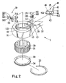
- Figure 2 is an exploded view of the ratchet wrench of Figure 1 .
- Figure 3 is a cutaway view of the ratchet wrench of Figure 1 .
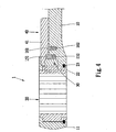
- Figure 4 is a cross-sectional view of the shown in Figure 1 .
- Figure 5 is a cross-sectional view of the ratchet wrench of Figure 11 in a position for driving a bolt or nut counterclockwise.
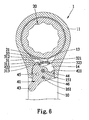
- Figure 6 is similar to Figure 5 but showing the ratchet wrench in a position for driving a bolt or nut clockwise.
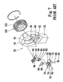
- Figure 7 is an exploded view of a ratchet wrench according to prior art.
- Figure 8 is a cross-sectional view of the ratchet wrench of Figure 7 .
- Figure 9 is a cross-sectional view of the ratchet wrench of Figure 7 in a position for driving a bolt or nut clockwise.
- Figure 10 is similar to Figure 9 but showing the ratchet wrench in a position for driving a bolt or nut counterclockwise.
- a ratchet wrench 1 includes a handle 10 and an annular head 11 from which the handle 10 projects.
- the annular head 11 defines a circular space 12, a crescent space 13 communicated with the circular space 12 and a semi-circular space 14 communicated with the crescent space 13.
- An annular groove 121 is defined in the wall of the circular space 12.
- Two recesses 15 and 16 are defined in the handle 10 near the semi-circular space 14.
- a direction controller 30 is put in the crescent space 13.
- the direction controller 30 includes two pawls 31 and 32 and a spring 33 for connecting the pawl 31 with the pawl 32.
- the pawl 31 includes a top, a bottom, a planar side, a toothed side 312, an arched side, a boss 311 formed on the planar side and rod 313 formed on the top.
- the pawl 32 includes a top, a bottom, a planar side, a toothed side 322, an arched side, a boss 321 formed on the planar side and rod 323 formed on the top.
- the spring 33 includes an end in which the boss 311 is fit and an opposite end in which the boss 321 is fit.
- the pawl 31 is firmly connected with the pawl 32 by means of the spring 33.
- an O-ring 22 is put in the circular space 12.
- the O-ring 22 includes an annular groove 24 defined in an external face thereof.
- a C-ring 23 includes an internal edge put in the annular groove 24 and an external edge put in the annular groove 121.
- the O-ring 22 is firmly attached to the annular head 11 by means of the C-ring 23.
- An annular gear 20 is put in the circular space 12.
- the annular gear 20 is put on the O-ring 22 rotationally.
- the annular gear 20 includes a toothed internal face for engagement with a bolt or nut and a toothed external face 21 for selective engagement with the pawl 31 or 32.
- a first spring 152 and a rod detent 151 are put in the first recess 15.
- a second spring 162 and a ball detent 161 are put in the second recess 16.
- a direction switch 40 includes a disc 41 and a lever 43 extending from the disc 41.
- the disc 41 includes a bottom in which a space 42, an aperture 44, and two recesses 45 and 46 are defined.
- the wall of the space 42 includes a first end 421 and a second end 422.
- the disc 41 is put in the semi-circular space 14.
- the rod detent 151 extends into the aperture 44.
- the direction switch 40 is installed on the handle 10 and the annular head 11 rotationally.
- the ball detent 161 selectively enters a recess 45 or 46.
- the direction switch 40 is in a first position.
- the ball detent 161 enters the first recess 45 so as to retain the direction switch 40 in the first position.
- the first end 421 of the wall of the space 42 pushes the rod 323.
- the pawl 31 is moved into a left-hand end of the crescent space 13.
- the annular head 11 can drive the annular gear 20 counterclockwise, but not vice versa.
- the direction switch 40 is in a second position.
- the ball detent 161 enters the second recess 46 so as to retain the direction switch 40 in the second position.
- the second end 422 of the wall of the space 42 pushes the rod 323.
- the pawl 32 is moved into a right-hand end of the crescent space 13.
- the annular head 11 can drive the annular gear 20 clockwise, but not vice versa.
Description
- The present invention relates to a ratchet wrench, according to the preamble of
independent claim 1. Such a wrench is known from documentGB 2 353 746 A - Referring to
Figures 7~10 , anotherconventional ratchet wrench 50 is shown, which includes ahandle 52 and anannular head 54 formed at an end of thehandle 52. Theannular head 52 defines acircular space 56, acrescent space 58 communicated with thecircular space 56, agroove 60 in a side thereof and arecess 62 communicated with the groove. - A
spring 64 and a ball detent 66 are put in therecess 62. - A
direction switch 68 is put in and can be moved along thegroove 60. Afriction plate 70 is formed on thedirection switch 68 for frictional contact with a user's finger. Thedirection switch 68 defines tworecesses space 76 in an opposite side. The ball detent 66 is put in therecess direction switch 68 in one of two positions. Thefriction plate 70 defines anaperture 80 communicated with thespace 76. - A V-shaped
elastic element 80 includes twohelical ends elastic element 78 is put in thespace 76. - As best shown in
Figure 8 , atab 86 is inserted in thespace 76 for preventing theelastic element 80 from faltering in thespace 76. Thetab 86 defines an aperture 88. - A
pin 90 is fit in theapertures 78 and 88 and put between thehelical ends elastic element 80 escaping thespace 76. - A
pawl 92 includes tworecesses teeth 98 formed on an opposite side. Thepawl 92 is put in thecrescent space 58. Thehelical end 82 can be put in therecess 94, or thehelical end 84 in therecess 96. - An
annular gear 100 is put in thecircular space 56. Theannular gear 100 includesteeth 102 formed on an external side thereof for engagement with theteeth 98. - Referring to
Figure 9 , thedirection switch 68 is moved to a right-hand end of thegroove 60 so that the ball detent 66 enters therecess 74. Via theelastic element 80, a right-hand end of thepawl 92 is moved to a right-hand end of thecrescent space 58. Thus, theannular head 10 can drive theannular gear 100 clockwise, but not vice versa. - Referring to
Figure 10 , thedirection switch 68 is moved to a left-hand end of thegroove 60 so that the ball detent 66 enters therecess 74. Via theelastic element 80, a left-hand end of thepawl 92 is moved to a left-hand end of thecrescent space 58. Thus, theannular head 10 can drive theannular gear 100 counterclockwise, but not vice versa. - This
conventional ratchet wrench 50 includes many elements. Many of its elements require fine fabrication, e.g., thedirection switch 68 and theelastic element 80. It takes a lot of time to fabricate these elements. It also takes a lot time to assemble these elements. Thisconventional ratchet wrench 50 is very complicated in structure. As result, the cost of manufacturing of thisconventional ratchet wrench 50 is high. - The present invention is therefore intended to obviate or at least alleviate the problems encountered in prior art.
- It is the primary objective of the present invention to provide a structurally simple ratchet wrench.
- According to the present invention, a ratchet wrench includes a handle and an annular head from which the handle projects. The annular head defines a first space, a second space communicated with the first space and a third space communicated with the second space. An annular gear is rotationally put in the first space. The annular gear includes a toothed external face. A direction controller is put in the second space. The direction controller includes two pawls and a spring installed between the pawls. Each of the pawls includes a toothed face. A direction switch which includes a disc is rotationally mounted on the handle and partially put in the third space for bringing the toothed face of selective one of the pawls into engagement with the toothed external face of the annular gear. The ratchet wrench further comprises a first spring and a rod detent disposed in a first recess defined in the handle near the third space. The rod detent extends into an aperture defined in a bottom of the disc so that said disc is retained in the third space defined by the annular head end is rotationally mounted on the handle.
- Other objects, advantages and novel features of the invention will become more apparent from the following detailed description in conjunction with the attached drawings.
- The present invention will be described via detailed illustration of the preferred embodiment referring to the drawings.
-
Figure 1 is a perspective view of a ratchet wrench according to the preferred embodiment of the present invention. -
Figure 2 is an exploded view of the ratchet wrench ofFigure 1 . -
Figure 3 is a cutaway view of the ratchet wrench ofFigure 1 . -
Figure 4 is a cross-sectional view of the shown inFigure 1 . -
Figure 5 is a cross-sectional view of the ratchet wrench of Figure 11 in a position for driving a bolt or nut counterclockwise. -
Figure 6 is similar toFigure 5 but showing the ratchet wrench in a position for driving a bolt or nut clockwise. -
Figure 7 is an exploded view of a ratchet wrench according to prior art. -
Figure 8 is a cross-sectional view of the ratchet wrench ofFigure 7 . -
Figure 9 is a cross-sectional view of the ratchet wrench ofFigure 7 in a position for driving a bolt or nut clockwise. -
Figure 10 is similar toFigure 9 but showing the ratchet wrench in a position for driving a bolt or nut counterclockwise. - Referring to
Figure 1 , according to the preferred embodiment of the present invention, aratchet wrench 1 includes ahandle 10 and anannular head 11 from which thehandle 10 projects. - Referring to
Figures 2 and3 , theannular head 11 defines acircular space 12, acrescent space 13 communicated with thecircular space 12 and asemi-circular space 14 communicated with thecrescent space 13. Anannular groove 121 is defined in the wall of thecircular space 12. Tworecesses handle 10 near thesemi-circular space 14. - A
direction controller 30 is put in thecrescent space 13. Thedirection controller 30 includes twopawls spring 33 for connecting thepawl 31 with thepawl 32. - The
pawl 31 includes a top, a bottom, a planar side, atoothed side 312, an arched side, aboss 311 formed on the planar side androd 313 formed on the top. - The
pawl 32 includes a top, a bottom, a planar side, atoothed side 322, an arched side, aboss 321 formed on the planar side androd 323 formed on the top. - The
spring 33 includes an end in which theboss 311 is fit and an opposite end in which theboss 321 is fit. Thus, thepawl 31 is firmly connected with thepawl 32 by means of thespring 33. - Referring to
Figures 2 and4 , an O-ring 22 is put in thecircular space 12. The O-ring 22 includes anannular groove 24 defined in an external face thereof. - A C-
ring 23 includes an internal edge put in theannular groove 24 and an external edge put in theannular groove 121. Thus, the O-ring 22 is firmly attached to theannular head 11 by means of the C-ring 23. - An
annular gear 20 is put in thecircular space 12. Theannular gear 20 is put on the O-ring 22 rotationally. Theannular gear 20 includes a toothed internal face for engagement with a bolt or nut and a toothedexternal face 21 for selective engagement with thepawl - A
first spring 152 and arod detent 151 are put in thefirst recess 15. - A
second spring 162 and aball detent 161 are put in thesecond recess 16. - A
direction switch 40 includes adisc 41 and alever 43 extending from thedisc 41. Thedisc 41 includes a bottom in which aspace 42, anaperture 44, and tworecesses space 42 includes afirst end 421 and asecond end 422. Thedisc 41 is put in thesemi-circular space 14. Therod detent 151 extends into theaperture 44. Thus, thedirection switch 40 is installed on thehandle 10 and theannular head 11 rotationally. Theball detent 161 selectively enters arecess - Referring to
Figure 5 , thedirection switch 40 is in a first position. Theball detent 161 enters thefirst recess 45 so as to retain thedirection switch 40 in the first position. Thefirst end 421 of the wall of thespace 42 pushes therod 323. Thus, thepawl 31 is moved into a left-hand end of thecrescent space 13. Thus, theannular head 11 can drive theannular gear 20 counterclockwise, but not vice versa. - Referring to
Figure 6 , thedirection switch 40 is in a second position. Theball detent 161 enters thesecond recess 46 so as to retain thedirection switch 40 in the second position. Thesecond end 422 of the wall of thespace 42 pushes therod 323. Thus, thepawl 32 is moved into a right-hand end of thecrescent space 13. Thus, theannular head 11 can drive theannular gear 20 clockwise, but not vice versa. - The present invention has been described via detailed illustration of the preferred embodiment. Those skilled in the art can derive variations from the preferred embodiment without departing from the scope of the present invention. Therefore, the preferred embodiment shall not limit the scope of the present invention defined in the claims.
Claims (10)
- A ratchet wrench including:a handle (10);an annular head (11) from which the handle (10) projects, the annular head (11) defining a first space (12), a second space (13) communicated with the first space (12) and a third space (14) communicated with the second space (13);an annular gear (20) rotationally put in the first space (12), the annular gear (20) including a toothed external face (21);a direction controller (30) put in the second space (13), the direction controller (30) including two pawls (31; 32) and a spring (33) installed between the pawls (31; 32), each of the pawls (31; 32) including a toothed face (312; 322); anda direction switch (40) including a disc (41) rotationally mounted on the handle (10) and partially put in the third space (14) for bringing the toothed face (312; 322) of selective one of the pawls (31; 32) into engagement with the toothed external face (21) of the annular gear (20), characterized in that it further comprises a first spring (152) and a rod detent (151) disposed in a first recess (15) defined in the handle (10) near the third space (14), the rod detent extending into an aperture (44) defined in a bottom of the disc (41) so that said disc is retained in the third space (14) defined by the annular head (11) and is rotationally mounted on the handle.
- The ratchet wrench according to claim 1 wherein the first space (12) is a circular space.
- The ratchet wrench according to claim 1 wherein the second space (13) is a crescent space.
- The ratchet wrench according to claim 1 wherein the third space (14) is a semi-circular space (14).
- The ratchet wrench according to claim 1 including a second spring-biased detent (161; 162), wherein the handle (10) defines a second recess (16) for receiving the second spring-biased detent (161; 162), and the disc (41) defines two recesses (45; 46), a selective one of which receives the spring-biased detent (161; 162) so that the disc (41) is retained in a selective one of two positions.
- The ratchet wrench according to claim 1 wherein each of the pawls (31; 32) includes a rod (313; 323), and the disc (41) defines a space (42) by means of a wall including two ends (421; 422) selective one of which can be engaged with one of the rods (313; 323) so as to engage the toothed face (312; 322) of one of the pawls (31; 32) with the toothed face (21) of the annular gear (20).
- The ratchet wrench according to claim 1, wherein the direction switch (40) further includes a lever (43) extending from the disc (41).
- The ratchet wrench according to claim 1 wherein each of the pawls (31; 32) includes a boss (311) formed thereon and fit in an end of the spring (33) so that it is firmly connected with the spring (33).
- The ratchet wrench according to claim 1 including an O-ring (22) fit in the first space (12) for supporting the annular gear (20).
- The ratchet wrench according to claim 8 including a C-ring (23), wherein the annular head (11) defines an annular groove (121) in an internal side for receiving an external edge of the C-ring (23), and the O-ring (22) defines an annular groove (24) in an external side for receiving an internal edge of the C-ring (23).
Priority Applications (2)
| Application Number | Priority Date | Filing Date | Title |
|---|---|---|---|
| EP03019148A EP1510293B1 (en) | 2003-08-25 | 2003-08-25 | Ratchet wrench |
| DE60321337T DE60321337D1 (en) | 2003-08-25 | 2003-08-25 | ratchet wrench |
Applications Claiming Priority (1)
| Application Number | Priority Date | Filing Date | Title |
|---|---|---|---|
| EP03019148A EP1510293B1 (en) | 2003-08-25 | 2003-08-25 | Ratchet wrench |
Publications (2)
| Publication Number | Publication Date |
|---|---|
| EP1510293A1 EP1510293A1 (en) | 2005-03-02 |
| EP1510293B1 true EP1510293B1 (en) | 2008-05-28 |
Family
ID=34089595
Family Applications (1)
| Application Number | Title | Priority Date | Filing Date |
|---|---|---|---|
| EP03019148A Expired - Lifetime EP1510293B1 (en) | 2003-08-25 | 2003-08-25 | Ratchet wrench |
Country Status (2)
| Country | Link |
|---|---|
| EP (1) | EP1510293B1 (en) |
| DE (1) | DE60321337D1 (en) |
Families Citing this family (4)
| Publication number | Priority date | Publication date | Assignee | Title |
|---|---|---|---|---|
| US20060117913A1 (en) * | 2003-08-27 | 2006-06-08 | Terence Chen | Selective one-way wrench |
| CN1332784C (en) * | 2003-12-01 | 2007-08-22 | 陈泰佐 | Selective one-way wrench |
| US8607671B2 (en) | 2010-08-06 | 2013-12-17 | American Grease Stick Company | Wrench with trigger |
| RU2554266C1 (en) * | 2014-01-09 | 2015-06-27 | И-Минь У | Multi-function wrench |
Family Cites Families (10)
| Publication number | Priority date | Publication date | Assignee | Title |
|---|---|---|---|---|
| US3436992A (en) * | 1967-03-10 | 1969-04-08 | Pendleton Tool Ind Inc | Reversible ratchet wrench with floating pawls |
| US5199330A (en) * | 1991-10-01 | 1993-04-06 | Easco Hand Tools, Inc. | Reversing ratchet wrench |
| US5174176A (en) * | 1991-12-09 | 1992-12-29 | Snap-On Tools Corporation | Reversible rachet wrench with integrated dual pawl and spring and cam unit |
| GB2353746B (en) * | 1999-09-04 | 2001-08-22 | Jack Lee | Ratchet tool |
| TW444633U (en) * | 2000-09-01 | 2001-07-01 | Hu Hou Fei | Ratchet tool |
| US6516930B2 (en) * | 2000-12-29 | 2003-02-11 | Ching Chen | Ratchet mechanism for tools |
| US6386072B1 (en) * | 2001-03-21 | 2002-05-14 | Chi Yuan-Chin | Ratchet tool |
| US6539825B1 (en) * | 2001-09-20 | 2003-04-01 | Yen-Wen Lin | Single direction ratcheting wrench with stuck prevention and ratcheting direction indication |
| US6513409B1 (en) * | 2002-01-25 | 2003-02-04 | Daniel Lee | Ratchet wrench structure |
| US6516692B1 (en) * | 2002-07-16 | 2003-02-11 | Chih-Ching Hsien | Pawl controlling device for ratchet tools |
-
2003
- 2003-08-25 EP EP03019148A patent/EP1510293B1/en not_active Expired - Lifetime
- 2003-08-25 DE DE60321337T patent/DE60321337D1/en not_active Expired - Lifetime
Also Published As
| Publication number | Publication date |
|---|---|
| EP1510293A1 (en) | 2005-03-02 |
| DE60321337D1 (en) | 2008-07-10 |
Similar Documents
| Publication | Publication Date | Title |
|---|---|---|
| US20050011315A1 (en) | Ratchet wrench | |
| US6666112B2 (en) | Switching arrangement for a reversible ratchet type wrench | |
| US6722234B2 (en) | Easy-to-operate and easy-to-assemble ratcheting-type wrench | |
| US5749272A (en) | Ratchet screw driver | |
| US8499666B2 (en) | Dual pawl ratchet mechanism and reversing method | |
| US7207244B2 (en) | Selective one-way wrench | |
| US6282991B1 (en) | Biasing arrangement for a pawl of a reversible ratchet-type wrench | |
| US7975574B2 (en) | Ratchet wrench with switch moving in transverse direction | |
| US7185565B1 (en) | Screwdriver having a ratchet mechanism | |
| US6644148B2 (en) | Reversible ratchet-type wrench | |
| US7017453B2 (en) | Reversible ratchet-type wrench | |
| US8250947B2 (en) | Ratchet wrench | |
| US20100037735A1 (en) | Ratchet Wrench with Three Operative Positions | |
| US20060117913A1 (en) | Selective one-way wrench | |
| US6971285B2 (en) | Selective one-way wrench | |
| US6584875B1 (en) | Ratchet wrench | |
| US20030196522A1 (en) | Reversible ratchet type wrench | |
| US6964216B2 (en) | Selective one-way wrench | |
| EP1510293B1 (en) | Ratchet wrench | |
| US6053077A (en) | Ratchet wrench having two driving stems | |
| US20110162486A1 (en) | Open end ratchet wrench | |
| US20070000357A1 (en) | Ratchet tool having operation levers on two sides of the tool | |
| EP1484135B1 (en) | Ratchet wrench | |
| US6647833B1 (en) | Ratchet wrench | |
| US7100477B2 (en) | Oneway ratchet wrench |
Legal Events
| Date | Code | Title | Description |
|---|---|---|---|
| PUAI | Public reference made under article 153(3) epc to a published international application that has entered the european phase |
Free format text: ORIGINAL CODE: 0009012 |
|
| 17P | Request for examination filed |
Effective date: 20030825 |
|
| AK | Designated contracting states |
Kind code of ref document: A1 Designated state(s): AT BE BG CH CY CZ DE DK EE ES FI FR GB GR HU IE IT LI LU MC NL PT RO SE SI SK TR |
|
| AX | Request for extension of the european patent |
Extension state: AL LT LV MK |
|
| AKX | Designation fees paid |
Designated state(s): DE ES FR GB IT |
|
| GRAP | Despatch of communication of intention to grant a patent |
Free format text: ORIGINAL CODE: EPIDOSNIGR1 |
|
| GRAS | Grant fee paid |
Free format text: ORIGINAL CODE: EPIDOSNIGR3 |
|
| GRAA | (expected) grant |
Free format text: ORIGINAL CODE: 0009210 |
|
| AK | Designated contracting states |
Kind code of ref document: B1 Designated state(s): DE ES FR GB IT |
|
| REG | Reference to a national code |
Ref country code: GB Ref legal event code: FG4D |
|
| REF | Corresponds to: |
Ref document number: 60321337 Country of ref document: DE Date of ref document: 20080710 Kind code of ref document: P |
|
| PG25 | Lapsed in a contracting state [announced via postgrant information from national office to epo] |
Ref country code: ES Free format text: LAPSE BECAUSE OF FAILURE TO SUBMIT A TRANSLATION OF THE DESCRIPTION OR TO PAY THE FEE WITHIN THE PRESCRIBED TIME-LIMIT Effective date: 20080908 |
|
| PLBE | No opposition filed within time limit |
Free format text: ORIGINAL CODE: 0009261 |
|
| STAA | Information on the status of an ep patent application or granted ep patent |
Free format text: STATUS: NO OPPOSITION FILED WITHIN TIME LIMIT |
|
| 26N | No opposition filed |
Effective date: 20090303 |
|
| REG | Reference to a national code |
Ref country code: FR Ref legal event code: PLFP Year of fee payment: 14 |
|
| REG | Reference to a national code |
Ref country code: FR Ref legal event code: PLFP Year of fee payment: 15 |
|
| REG | Reference to a national code |
Ref country code: FR Ref legal event code: PLFP Year of fee payment: 16 |
|
| PGFP | Annual fee paid to national office [announced via postgrant information from national office to epo] |
Ref country code: GB Payment date: 20220607 Year of fee payment: 20 |
|
| PGFP | Annual fee paid to national office [announced via postgrant information from national office to epo] |
Ref country code: IT Payment date: 20220808 Year of fee payment: 20 Ref country code: DE Payment date: 20220808 Year of fee payment: 20 |
|
| PGFP | Annual fee paid to national office [announced via postgrant information from national office to epo] |
Ref country code: FR Payment date: 20220818 Year of fee payment: 20 |
|
| REG | Reference to a national code |
Ref country code: DE Ref legal event code: R071 Ref document number: 60321337 Country of ref document: DE |
|
| REG | Reference to a national code |
Ref country code: GB Ref legal event code: PE20 Expiry date: 20230824 |
|
| PG25 | Lapsed in a contracting state [announced via postgrant information from national office to epo] |
Ref country code: GB Free format text: LAPSE BECAUSE OF EXPIRATION OF PROTECTION Effective date: 20230824 |