EP1510293B1 - Ratschenschlüssel - Google Patents
Ratschenschlüssel Download PDFInfo
- Publication number
- EP1510293B1 EP1510293B1 EP03019148A EP03019148A EP1510293B1 EP 1510293 B1 EP1510293 B1 EP 1510293B1 EP 03019148 A EP03019148 A EP 03019148A EP 03019148 A EP03019148 A EP 03019148A EP 1510293 B1 EP1510293 B1 EP 1510293B1
- Authority
- EP
- European Patent Office
- Prior art keywords
- space
- ratchet wrench
- disc
- spring
- pawls
- Prior art date
- Legal status (The legal status is an assumption and is not a legal conclusion. Google has not performed a legal analysis and makes no representation as to the accuracy of the status listed.)
- Expired - Lifetime
Links
- 230000000717 retained effect Effects 0.000 claims description 3
- 238000004519 manufacturing process Methods 0.000 description 2
Images


Classifications
-
- B—PERFORMING OPERATIONS; TRANSPORTING
- B25—HAND TOOLS; PORTABLE POWER-DRIVEN TOOLS; MANIPULATORS
- B25B—TOOLS OR BENCH DEVICES NOT OTHERWISE PROVIDED FOR, FOR FASTENING, CONNECTING, DISENGAGING OR HOLDING
- B25B13/00—Spanners; Wrenches
- B25B13/46—Spanners; Wrenches of the ratchet type, for providing a free return stroke of the handle
- B25B13/461—Spanners; Wrenches of the ratchet type, for providing a free return stroke of the handle with concentric driving and driven member
- B25B13/462—Spanners; Wrenches of the ratchet type, for providing a free return stroke of the handle with concentric driving and driven member the ratchet parts engaging in a direction radial to the tool operating axis
- B25B13/463—Spanners; Wrenches of the ratchet type, for providing a free return stroke of the handle with concentric driving and driven member the ratchet parts engaging in a direction radial to the tool operating axis a pawl engaging an externally toothed wheel
Definitions
- the present invention relates to a ratchet wrench, according to the preamble of independent claim 1.
- a wrench is known from document GB 2 353 746 A .
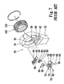
- FIG. 7 ⁇ 10 another conventional ratchet wrench 50 is shown, which includes a handle 52 and an annular head 54 formed at an end of the handle 52.
- the annular head 52 defines a circular space 56, a crescent space 58 communicated with the circular space 56, a groove 60 in a side thereof and a recess 62 communicated with the groove.
- a spring 64 and a ball detent 66 are put in the recess 62.
- a direction switch 68 is put in and can be moved along the groove 60.
- a friction plate 70 is formed on the direction switch 68 for frictional contact with a user's finger.
- the direction switch 68 defines two recesses 72 and 74 in a side and a space 76 in an opposite side.
- the ball detent 66 is put in the recess 72 or 74 for keeping the direction switch 68 in one of two positions.
- the friction plate 70 defines an aperture 80 communicated with the space 76.
- a V-shaped elastic element 80 includes two helical ends 82 and 84.
- the V-shaped elastic element 78 is put in the space 76.
- a tab 86 is inserted in the space 76 for preventing the elastic element 80 from faltering in the space 76.
- the tab 86 defines an aperture 88.
- a pin 90 is fit in the apertures 78 and 88 and put between the helical ends 82 and 84 so as to avoid the elastic element 80 escaping the space 76.
- a pawl 92 includes two recesses 94 and 96 defined in a side and teeth 98 formed on an opposite side.
- the pawl 92 is put in the crescent space 58.
- the helical end 82 can be put in the recess 94, or the helical end 84 in the recess 96.
- the annular gear 100 is put in the circular space 56.
- the annular gear 100 includes teeth 102 formed on an external side thereof for engagement with the teeth 98.
- the direction switch 68 is moved to a right-hand end of the groove 60 so that the ball detent 66 enters the recess 74.
- a right-hand end of the pawl 92 is moved to a right-hand end of the crescent space 58.
- the annular head 10 can drive the annular gear 100 clockwise, but not vice versa.
- the direction switch 68 is moved to a left-hand end of the groove 60 so that the ball detent 66 enters the recess 74.
- a left-hand end of the pawl 92 is moved to a left-hand end of the crescent space 58.
- the annular head 10 can drive the annular gear 100 counterclockwise, but not vice versa.
- This conventional ratchet wrench 50 includes many elements. Many of its elements require fine fabrication, e.g., the direction switch 68 and the elastic element 80. It takes a lot of time to fabricate these elements. It also takes a lot time to assemble these elements. This conventional ratchet wrench 50 is very complicated in structure. As result, the cost of manufacturing of this conventional ratchet wrench 50 is high.
- the present invention is therefore intended to obviate or at least alleviate the problems encountered in prior art.
- a ratchet wrench includes a handle and an annular head from which the handle projects.
- the annular head defines a first space, a second space communicated with the first space and a third space communicated with the second space.
- An annular gear is rotationally put in the first space.
- the annular gear includes a toothed external face.
- a direction controller is put in the second space.
- the direction controller includes two pawls and a spring installed between the pawls. Each of the pawls includes a toothed face.
- a direction switch which includes a disc is rotationally mounted on the handle and partially put in the third space for bringing the toothed face of selective one of the pawls into engagement with the toothed external face of the annular gear.
- the ratchet wrench further comprises a first spring and a rod detent disposed in a first recess defined in the handle near the third space.
- the rod detent extends into an aperture defined in a bottom of the disc so that said disc is retained in the third space defined by the annular head end is rotationally mounted on the handle.
- Figure 1 is a perspective view of a ratchet wrench according to the preferred embodiment of the present invention.
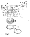
- Figure 2 is an exploded view of the ratchet wrench of Figure 1 .
- Figure 3 is a cutaway view of the ratchet wrench of Figure 1 .
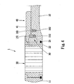
- Figure 4 is a cross-sectional view of the shown in Figure 1 .
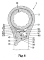
- Figure 5 is a cross-sectional view of the ratchet wrench of Figure 11 in a position for driving a bolt or nut counterclockwise.
- Figure 6 is similar to Figure 5 but showing the ratchet wrench in a position for driving a bolt or nut clockwise.
- Figure 7 is an exploded view of a ratchet wrench according to prior art.
- Figure 8 is a cross-sectional view of the ratchet wrench of Figure 7 .
- Figure 9 is a cross-sectional view of the ratchet wrench of Figure 7 in a position for driving a bolt or nut clockwise.
- Figure 10 is similar to Figure 9 but showing the ratchet wrench in a position for driving a bolt or nut counterclockwise.
- a ratchet wrench 1 includes a handle 10 and an annular head 11 from which the handle 10 projects.
- the annular head 11 defines a circular space 12, a crescent space 13 communicated with the circular space 12 and a semi-circular space 14 communicated with the crescent space 13.
- An annular groove 121 is defined in the wall of the circular space 12.
- Two recesses 15 and 16 are defined in the handle 10 near the semi-circular space 14.
- a direction controller 30 is put in the crescent space 13.
- the direction controller 30 includes two pawls 31 and 32 and a spring 33 for connecting the pawl 31 with the pawl 32.
- the pawl 31 includes a top, a bottom, a planar side, a toothed side 312, an arched side, a boss 311 formed on the planar side and rod 313 formed on the top.
- the pawl 32 includes a top, a bottom, a planar side, a toothed side 322, an arched side, a boss 321 formed on the planar side and rod 323 formed on the top.
- the spring 33 includes an end in which the boss 311 is fit and an opposite end in which the boss 321 is fit.
- the pawl 31 is firmly connected with the pawl 32 by means of the spring 33.
- an O-ring 22 is put in the circular space 12.
- the O-ring 22 includes an annular groove 24 defined in an external face thereof.
- a C-ring 23 includes an internal edge put in the annular groove 24 and an external edge put in the annular groove 121.
- the O-ring 22 is firmly attached to the annular head 11 by means of the C-ring 23.
- An annular gear 20 is put in the circular space 12.
- the annular gear 20 is put on the O-ring 22 rotationally.
- the annular gear 20 includes a toothed internal face for engagement with a bolt or nut and a toothed external face 21 for selective engagement with the pawl 31 or 32.
- a first spring 152 and a rod detent 151 are put in the first recess 15.
- a second spring 162 and a ball detent 161 are put in the second recess 16.
- a direction switch 40 includes a disc 41 and a lever 43 extending from the disc 41.
- the disc 41 includes a bottom in which a space 42, an aperture 44, and two recesses 45 and 46 are defined.
- the wall of the space 42 includes a first end 421 and a second end 422.
- the disc 41 is put in the semi-circular space 14.
- the rod detent 151 extends into the aperture 44.
- the direction switch 40 is installed on the handle 10 and the annular head 11 rotationally.
- the ball detent 161 selectively enters a recess 45 or 46.
- the direction switch 40 is in a first position.
- the ball detent 161 enters the first recess 45 so as to retain the direction switch 40 in the first position.
- the first end 421 of the wall of the space 42 pushes the rod 323.
- the pawl 31 is moved into a left-hand end of the crescent space 13.
- the annular head 11 can drive the annular gear 20 counterclockwise, but not vice versa.
- the direction switch 40 is in a second position.
- the ball detent 161 enters the second recess 46 so as to retain the direction switch 40 in the second position.
- the second end 422 of the wall of the space 42 pushes the rod 323.
- the pawl 32 is moved into a right-hand end of the crescent space 13.
- the annular head 11 can drive the annular gear 20 clockwise, but not vice versa.
Landscapes
- Engineering & Computer Science (AREA)
- Mechanical Engineering (AREA)
- Details Of Spanners, Wrenches, And Screw Drivers And Accessories (AREA)
Claims (10)
- Ratschenschlüssel, aufweisend:einen Griff (10);einen ringförmigen Kopf (11), von welchem der Griff (10) vorragt, wobei der ringförmige Kopf (11) einen ersten Raum (12), einen mit dem ersten Raum (12) in Verbindung stehenden zweiten Raum (13) und einen mit dem zweiten Raum (13) in Verbindung stehenden dritten Raum (14) definiert;ein ringförmiges Getrieberad (20), welches drehbar in den ersten Raum (12) gesetzt ist, wobei das ringförmige Getrieberad (20) eine gezahnte äußere Fläche (21) aufweist;einen Richtungssteuerer (30), welcher in den zweiten Raum (13) gesetzt ist, wobei der Richtungssteuerer (30) zwei Krallen (31; 32) und eine Feder (33) aufweist, welche zwischen den Krallen (31; 32) installiert ist, wobei jede der Krallen (31; 32) eine gezahnte Fläche (312; 322) aufweist; undeinen Richtungsschalter (40), der eine Scheibe (41) aufweist, die drehbar an dem Griff (10) angebracht ist und zum Teil in den dritten Raum (14) gesetzt ist, um die gezahnte Fläche (312, 322) von wahlweise einer der Krallen (31; 32) in Kopplung mit der gezahnten äußeren Fläche (21) des ringförmigen Getrieberads (20) zu bringen,dadurch gekennzeichnet, daß er weiter eine erste Feder (152) und eine Stangenarretierung (151) aufweist, die in einer in dem Griff (10) nahe dem dritten Raum (15) definierten ersten Ausnehmung (15) angeordnet sind, wobei die Stangenarretierung sich in eine an einer Unterseite der Scheibe (41) definierte Öffnung (44) derart erstreckt, daß die Scheibe in dem von dem ringförmigen Kopf (11) definierten dritten Raum (14) gehalten ist und drehbar an dem Griff angebracht ist.
- Ratschenschlüssel nach Anspruch 1, bei dem der erste Raum (12) ein kreisförmiger Raum ist.
- Ratschenschlüssel nach Anspruch 1, bei dem der zweite Raum (13) ein halbmondförmiger Raum ist.
- Ratschenschlüssel nach Anspruch 1, bei dem der dritte Raum (14) ein halbkreisförmiger Raum (14) ist.
- Ratschenschlüssel nach Anspruch 1, aufweisend eine zweite feder-vorgespannte Arretierung (161; 162) wobei der Griff (10) eine zweite Ausnehmung (16) zur Aufnahme der zweiten feder-vorgespannten Arretierung (161; 162) definiert, und die Scheibe (41) zwei Ausnehmungen (45; 46) definiert, von denen eine ausgewählte die feder-vorgespannte Arretierung (161; 162) derart aufnimmt, daß die Scheibe (41) in einer ausgewählten von zwei Stellung gehalten wird.
- Ratschenschlüssel nach Anspruch 1, bei dem jede der Krallen (31, 32) eine Stange (313; 323) aufweist, und die Scheibe (41) einen Raum (42) mittels einer Wand definiert, die zwei Enden (421, 422) umfaßt, von denen ein ausgewähltes mit einer der Stangen (313; 323) gekoppelt werden kann, um die gezahnte Fläche (312; 322) einer der Krallen (31; 32) mit der gezahnten Fläche (21) des ringförmigen Getrieberads (20) in Eingriff zu bringen.
- Ratschenschlüssel nach Anspruch 1, bei dem der Richtungsschalter (40) weiter einen Hebel (43) aufweist, der sich von der Scheibe (41) erstreckt.
- Ratschenschlüssel nach Anspruch 1, bei dem jede der Krallen (31; 32) einen Vorsprung (311) aufweist, der daran gebildet ist und in ein Ende der Feder (33) eingepaßt ist, so daß sie fest mit der Feder (33) verbunden ist.
- Ratschenschlüssel nach Anspruch 1, aufweisend einen O-Ring (22), der in den ersten Raum (12) zum Tragen des ringförmigen Getrieberads (20) eingepaßt ist.
- Ratschenschlüssel nach Anspruch 8, aufweisend einen C-Ring (23), wobei der ringförmige Kopf (11) eine ringförmige Rinne (121) an einer Innenseite zur Aufnahme eines äußeren Randes des C-Rings (23) definiert, und der O-Ring (22) eine ringförmige Rinne (24) an einer äußeren Seite zur Aufnahme eines inneren Randes des C-Rings (23) definiert.
Priority Applications (2)
| Application Number | Priority Date | Filing Date | Title |
|---|---|---|---|
| DE60321337T DE60321337D1 (de) | 2003-08-25 | 2003-08-25 | Ratschenschlüssel |
| EP03019148A EP1510293B1 (de) | 2003-08-25 | 2003-08-25 | Ratschenschlüssel |
Applications Claiming Priority (1)
| Application Number | Priority Date | Filing Date | Title |
|---|---|---|---|
| EP03019148A EP1510293B1 (de) | 2003-08-25 | 2003-08-25 | Ratschenschlüssel |
Publications (2)
| Publication Number | Publication Date |
|---|---|
| EP1510293A1 EP1510293A1 (de) | 2005-03-02 |
| EP1510293B1 true EP1510293B1 (de) | 2008-05-28 |
Family
ID=34089595
Family Applications (1)
| Application Number | Title | Priority Date | Filing Date |
|---|---|---|---|
| EP03019148A Expired - Lifetime EP1510293B1 (de) | 2003-08-25 | 2003-08-25 | Ratschenschlüssel |
Country Status (2)
| Country | Link |
|---|---|
| EP (1) | EP1510293B1 (de) |
| DE (1) | DE60321337D1 (de) |
Families Citing this family (5)
| Publication number | Priority date | Publication date | Assignee | Title |
|---|---|---|---|---|
| US20060117913A1 (en) * | 2003-08-27 | 2006-06-08 | Terence Chen | Selective one-way wrench |
| CN1332784C (zh) * | 2003-12-01 | 2007-08-22 | 陈泰佐 | 换向驱动旋转扳手 |
| US8607671B2 (en) | 2010-08-06 | 2013-12-17 | American Grease Stick Company | Wrench with trigger |
| RU2554266C1 (ru) * | 2014-01-09 | 2015-06-27 | И-Минь У | Многофункциональный гаечный ключ |
| TW202327820A (zh) | 2021-09-13 | 2023-07-16 | 美商米沃奇電動工具公司 | 具棘輪機構的工具 |
Family Cites Families (10)
| Publication number | Priority date | Publication date | Assignee | Title |
|---|---|---|---|---|
| US3436992A (en) * | 1967-03-10 | 1969-04-08 | Pendleton Tool Ind Inc | Reversible ratchet wrench with floating pawls |
| US5199330A (en) * | 1991-10-01 | 1993-04-06 | Easco Hand Tools, Inc. | Reversing ratchet wrench |
| US5174176A (en) * | 1991-12-09 | 1992-12-29 | Snap-On Tools Corporation | Reversible rachet wrench with integrated dual pawl and spring and cam unit |
| GB2353746B (en) * | 1999-09-04 | 2001-08-22 | Jack Lee | Ratchet tool |
| TW444633U (en) * | 2000-09-01 | 2001-07-01 | Hu Hou Fei | Ratchet tool |
| US6516930B2 (en) * | 2000-12-29 | 2003-02-11 | Ching Chen | Ratchet mechanism for tools |
| US6386072B1 (en) * | 2001-03-21 | 2002-05-14 | Chi Yuan-Chin | Ratchet tool |
| US6539825B1 (en) * | 2001-09-20 | 2003-04-01 | Yen-Wen Lin | Single direction ratcheting wrench with stuck prevention and ratcheting direction indication |
| US6513409B1 (en) * | 2002-01-25 | 2003-02-04 | Daniel Lee | Ratchet wrench structure |
| DE20210730U1 (de) * | 2002-07-16 | 2002-11-14 | Hsien, Chih-Ching, Feng Yuan, Taichung | Ratschenschlüssel mit Umschaltmechanismus |
-
2003
- 2003-08-25 EP EP03019148A patent/EP1510293B1/de not_active Expired - Lifetime
- 2003-08-25 DE DE60321337T patent/DE60321337D1/de not_active Expired - Lifetime
Also Published As
| Publication number | Publication date |
|---|---|
| DE60321337D1 (de) | 2008-07-10 |
| EP1510293A1 (de) | 2005-03-02 |
Similar Documents
| Publication | Publication Date | Title |
|---|---|---|
| US20050011315A1 (en) | Ratchet wrench | |
| US6722234B2 (en) | Easy-to-operate and easy-to-assemble ratcheting-type wrench | |
| US6666112B2 (en) | Switching arrangement for a reversible ratchet type wrench | |
| US5749272A (en) | Ratchet screw driver | |
| US6732614B2 (en) | Easy-to-manufacture and easy-to-assemble ratcheting-type wrench | |
| US6644148B2 (en) | Reversible ratchet-type wrench | |
| US7975574B2 (en) | Ratchet wrench with switch moving in transverse direction | |
| US8499666B2 (en) | Dual pawl ratchet mechanism and reversing method | |
| US7017453B2 (en) | Reversible ratchet-type wrench | |
| US8250947B2 (en) | Ratchet wrench | |
| US20100037735A1 (en) | Ratchet Wrench with Three Operative Positions | |
| US6584875B1 (en) | Ratchet wrench | |
| US20030196522A1 (en) | Reversible ratchet type wrench | |
| US6971285B2 (en) | Selective one-way wrench | |
| US7185565B1 (en) | Screwdriver having a ratchet mechanism | |
| US6601477B2 (en) | Wrench adaptor allowing reversible operation | |
| US6964216B2 (en) | Selective one-way wrench | |
| US6053077A (en) | Ratchet wrench having two driving stems | |
| US7207244B2 (en) | Selective one-way wrench | |
| EP1510293B1 (de) | Ratschenschlüssel | |
| US20060117913A1 (en) | Selective one-way wrench | |
| EP1484135B1 (de) | Ratschenschlüssel | |
| US7100477B2 (en) | Oneway ratchet wrench | |
| US6862956B1 (en) | Ratchet wrench | |
| US6874391B2 (en) | One-way ratchet wrench |
Legal Events
| Date | Code | Title | Description |
|---|---|---|---|
| PUAI | Public reference made under article 153(3) epc to a published international application that has entered the european phase |
Free format text: ORIGINAL CODE: 0009012 |
|
| 17P | Request for examination filed |
Effective date: 20030825 |
|
| AK | Designated contracting states |
Kind code of ref document: A1 Designated state(s): AT BE BG CH CY CZ DE DK EE ES FI FR GB GR HU IE IT LI LU MC NL PT RO SE SI SK TR |
|
| AX | Request for extension of the european patent |
Extension state: AL LT LV MK |
|
| AKX | Designation fees paid |
Designated state(s): DE ES FR GB IT |
|
| GRAP | Despatch of communication of intention to grant a patent |
Free format text: ORIGINAL CODE: EPIDOSNIGR1 |
|
| GRAS | Grant fee paid |
Free format text: ORIGINAL CODE: EPIDOSNIGR3 |
|
| GRAA | (expected) grant |
Free format text: ORIGINAL CODE: 0009210 |
|
| AK | Designated contracting states |
Kind code of ref document: B1 Designated state(s): DE ES FR GB IT |
|
| REG | Reference to a national code |
Ref country code: GB Ref legal event code: FG4D |
|
| REF | Corresponds to: |
Ref document number: 60321337 Country of ref document: DE Date of ref document: 20080710 Kind code of ref document: P |
|
| PG25 | Lapsed in a contracting state [announced via postgrant information from national office to epo] |
Ref country code: ES Free format text: LAPSE BECAUSE OF FAILURE TO SUBMIT A TRANSLATION OF THE DESCRIPTION OR TO PAY THE FEE WITHIN THE PRESCRIBED TIME-LIMIT Effective date: 20080908 |
|
| PLBE | No opposition filed within time limit |
Free format text: ORIGINAL CODE: 0009261 |
|
| STAA | Information on the status of an ep patent application or granted ep patent |
Free format text: STATUS: NO OPPOSITION FILED WITHIN TIME LIMIT |
|
| 26N | No opposition filed |
Effective date: 20090303 |
|
| REG | Reference to a national code |
Ref country code: FR Ref legal event code: PLFP Year of fee payment: 14 |
|
| REG | Reference to a national code |
Ref country code: FR Ref legal event code: PLFP Year of fee payment: 15 |
|
| REG | Reference to a national code |
Ref country code: FR Ref legal event code: PLFP Year of fee payment: 16 |
|
| PGFP | Annual fee paid to national office [announced via postgrant information from national office to epo] |
Ref country code: GB Payment date: 20220607 Year of fee payment: 20 |
|
| PGFP | Annual fee paid to national office [announced via postgrant information from national office to epo] |
Ref country code: IT Payment date: 20220808 Year of fee payment: 20 Ref country code: DE Payment date: 20220808 Year of fee payment: 20 |
|
| PGFP | Annual fee paid to national office [announced via postgrant information from national office to epo] |
Ref country code: FR Payment date: 20220818 Year of fee payment: 20 |
|
| REG | Reference to a national code |
Ref country code: DE Ref legal event code: R071 Ref document number: 60321337 Country of ref document: DE |
|
| REG | Reference to a national code |
Ref country code: GB Ref legal event code: PE20 Expiry date: 20230824 |
|
| PG25 | Lapsed in a contracting state [announced via postgrant information from national office to epo] |
Ref country code: GB Free format text: LAPSE BECAUSE OF EXPIRATION OF PROTECTION Effective date: 20230824 |