EP1510290A1 - Eyeglass lens processing apparatus - Google Patents
Eyeglass lens processing apparatus Download PDFInfo
- Publication number
- EP1510290A1 EP1510290A1 EP04020466A EP04020466A EP1510290A1 EP 1510290 A1 EP1510290 A1 EP 1510290A1 EP 04020466 A EP04020466 A EP 04020466A EP 04020466 A EP04020466 A EP 04020466A EP 1510290 A1 EP1510290 A1 EP 1510290A1
- Authority
- EP
- European Patent Office
- Prior art keywords
- grindstone
- lens
- rotating shaft
- bevel
- beveling
- Prior art date
- Legal status (The legal status is an assumption and is not a legal conclusion. Google has not performed a legal analysis and makes no representation as to the accuracy of the status listed.)
- Granted
Links
Images


Classifications
-
- B—PERFORMING OPERATIONS; TRANSPORTING
- B24—GRINDING; POLISHING
- B24B—MACHINES, DEVICES, OR PROCESSES FOR GRINDING OR POLISHING; DRESSING OR CONDITIONING OF ABRADING SURFACES; FEEDING OF GRINDING, POLISHING, OR LAPPING AGENTS
- B24B9/00—Machines or devices designed for grinding edges or bevels on work or for removing burrs; Accessories therefor
- B24B9/02—Machines or devices designed for grinding edges or bevels on work or for removing burrs; Accessories therefor characterised by a special design with respect to properties of materials specific to articles to be ground
- B24B9/06—Machines or devices designed for grinding edges or bevels on work or for removing burrs; Accessories therefor characterised by a special design with respect to properties of materials specific to articles to be ground of non-metallic inorganic material, e.g. stone, ceramics, porcelain
- B24B9/08—Machines or devices designed for grinding edges or bevels on work or for removing burrs; Accessories therefor characterised by a special design with respect to properties of materials specific to articles to be ground of non-metallic inorganic material, e.g. stone, ceramics, porcelain of glass
- B24B9/14—Machines or devices designed for grinding edges or bevels on work or for removing burrs; Accessories therefor characterised by a special design with respect to properties of materials specific to articles to be ground of non-metallic inorganic material, e.g. stone, ceramics, porcelain of glass of optical work, e.g. lenses, prisms
- B24B9/148—Machines or devices designed for grinding edges or bevels on work or for removing burrs; Accessories therefor characterised by a special design with respect to properties of materials specific to articles to be ground of non-metallic inorganic material, e.g. stone, ceramics, porcelain of glass of optical work, e.g. lenses, prisms electrically, e.g. numerically, controlled
-
- B—PERFORMING OPERATIONS; TRANSPORTING
- B24—GRINDING; POLISHING
- B24B—MACHINES, DEVICES, OR PROCESSES FOR GRINDING OR POLISHING; DRESSING OR CONDITIONING OF ABRADING SURFACES; FEEDING OF GRINDING, POLISHING, OR LAPPING AGENTS
- B24B27/00—Other grinding machines or devices
- B24B27/0076—Other grinding machines or devices grinding machines comprising two or more grinding tools
Definitions
- the present invention is related to an eyeglass lens processing apparatus forprocessingtheperipheryof the eyeglass lenses.
- the processing is performed on the lens periphery to form a reverse V-shaped bevel to be fitted into a V-shaped groove in the inside of the frame.
- This beveling is carried out by a beveling grindstone having a V-shaped beveling groove.
- the beveling grindstone is ordinarily cylindrical having a diameter of more than 100 mm, in view of consumption, similarly to a roughing grindstone.
- the invention is characterized by providing the under mentioned structures.
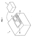
- Figure 1 is a schematic diagram of the eyeglass lens processing apparatus according to the invention.
- a main body 1 of the apparatus is connected to an eyeglass frame shape (target lens shape) measuring unit 2.
- the main body 1 is equipped with a display 415 for displaying processing information and an operation panel portion 420 with various switches.
- Reference number 402 designates an opening window for a processing room.
- Figs. 2 and 3 are schematic diagram of a lens processing portion equipped within the main body 1.
- Fig. 2 is a view seen from the upper part of the processing portion 5.
- Fig. 3 is a view seen from the right side of the processing portion 5.
- the main body 1 is provided with a lens shape measuring unit to which known units (described in US Re.35, 898 (Japanese Patent Laid Open No.212661/1993), or EP1310326 A1 (Japanese Patent Laid Open No. 2003-145400)) may be applied, and thus explanation will be omitted.
- a carriage 100, a first grinding portion 200 and a second grinding portion 250 are arranged on a base 10.
- An eyeglass lens LE to be processed is chucked and held by two lens rotating shafts 110L, 110R of the carriage portion 100, and is subjected to a grinding (edging) on the periphery by the first and second grinding portions 200 and 250.
- the first grinding portion 200 is disposed on the front side of the carriage portion 100, and includes a roughing grindstone 201a for glasses, a roughing grindstone 201b for plastics, and a large diameter bevel finishing grindstone 201c (beveling and flat-edging grindstone) 201c having a V-shaped beveling groove 202a for beveling (finishing) and a flat processing face 202b for flat-edging (finishing).
- the finishing grindstone 201c may be the beveling grindstone having only the beveling groove 202a.
- These grindstones 201a, 201b, 201c are coaxially (each of the rotation axes is coaxial) disposed (attached) on a grindstone rotating shaft 203.
- the shaft 203 is rotatably pivoted on a spindle unit 205 secured on the base 10, and is connected at its end to a motor 207.
- the shaft 203 is rotated by driving of the motor 207, thereby to rotate the grindstones 201a, 201b, 201c.
- the grindstones 201a, 201b, 201c are cylindrical, and approximately 100 mm in diameter for lengthening lives to abrasion.
- the grindstone 201c is used when a path of the bevel to be formed has a comparatively moderate curve (in case a curve value Crv is less than 6).
- the carriage portion 100 includes a carriage base 101 which is movable along two rail shafts 107 extending in a direction of the rotation axis of the shaft 203 (called as "X-axial direction” hereafter) and secured on the base 10.
- a rack 103 extending in the X-axial direction is fixed to a rear side of the carriage base 101, and is connected to a pinion 104 mounted on a rotation shaft of a pulse motor 105 secured on the base 10.
- the rack 103 is moved by driving the motor 105, so that the carriage base 101 is moved in the X-axial direction.
- a carriage 112 having approximately U-shape seen from a front side is mounted on the carriage base 101.
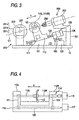
- Fig. 4 is a schematic diagram of the carriage 112 seen from the front side.
- the carriage 112 is provided with an upward extending left arm 112L and right arm 112R, the left arm 112L holding the shaft 110L and the right arm 112R holding the shaft 110R, and both shafts 110L, 110R being held rotatably and coaxially in the X-axial direction (each of the rotation axes is coaxial).
- the shaft 110R is movable in the direction of the rotation axis (X-axial direction) by the motor 115 fixed to the right side of the carriage 112 and by a moving mechanism 116 such as a feed screw provided inside of the right arm 112R, so that the lens LE is chucked and held by the shafts 110L, 110R.
- a shaft 120 extending in the X-axial direction and disposed within the carriage 112 is connected to the rotating shaft of the motor 117 fixed to the right side of the carriage 112.
- the shaft 120 is connected to the shaft 110L via a belt 121 and also to the shaft 110R via a belt 122.
- the shaft 120 is rotated by driving of the motor 117, so that the shafts 110L, 110R are simultaneously (synchronously) rotated.
- the carriage base 101 is secured with two rail shafts 131 extending in parallel in a direction of changing a distance between the rotation axis of the shaft 203 and the rotation axes of the shafts 110L, 110R (called as "Y-axial direction” hereafter).
- the Y-axial direction in the present embodiment tilts approximately 15 degrees toward this side (the front side) , and the upper surface of the carriage base 101 also tilts toward this side (see Figure 3).
- the carriage 112 is displaced movably in the Y-axial direction along the shafts 131.
- the motor 135 is fixed to a rear side of the carriage base 101, and is connected, on its rotating shaft, to a feed screw 133 extending in the Y-axial direction.
- the screw 133 is rotated by driving of the motor 135, so that the carriage 112 is moved in the Y-axial direction.
- a servomotor provided with an encoder 136 for detecting rotation is employed.
- rotation torque (motor load current) of themotor 135 is detected, and voltage supplied to the motor 135 is controlled on the basis of detected results, so that a processing pressure of the lens LE to the grindstone is controlled.
- Position information of moving the carriage 112 is detected on the basis of a signal issued from the encoder 136, and the processing finish is judged.
- the second grinding portion 250 is secured on the base 10 via an attaching member 201 so as to be positioned at the inner part of the carriage portion 100.
- Fig. 5 is a schematic diagram of the second grinding portion 250.
- the second grinding portion 250 is provided with a motor 253, an L-shaped support 257 rotatably supporting a rotating shaft 255 connected to the motor 253 and a grindstone rotating shaft 260, a grinding portion 270 and a drilling tool 280 disposed (attached) to the shaft 260.
- the rotation of the shaft 255 by driving of the motor 253 is transmitted to the shaft 260 via bevel gears 258, 261, so that the grinding portion 270 and the drilling tool 280 are rotated.
- the rotation axis of the shaft 260, the rotation axes of the shafts 110L, 110R and the rotation axis of the shaft 203 are arranged to be positioned on the same plane 01 (see Fig. 3).
- the rotation axis of the shaft 260 tilt with respect to the rotation axes of the shafts 110L, 110R (X-axial direction) on the same plane 01 (see Fig. 5).
- the tilting angle ⁇ 1 is preferably 5 to 15 degrees, and in the present embodiment, it is approximately 10 degrees.
- the grinding portion 270 is provided with a small diameter conically shaped beveling grindstone 271 having a V-shaped beveling groove 271a, a chamfering grindstone 272 for a lens front surface, a chamfering grindstone 273 for a lens rear surface, and a grooving grindstone 274.
- the grindstone 271 is smaller in diameter than the grindstone 201c, desirably less than half of the grindstone 201c. Thereby, the bevel can be restrained from becoming thin, even if the path of the bevel to be formed has a comparatively tight curve (in case the curve value Crv is more than 6).
- the diameter of the grindstone 271 (the smallest diameter of the groove 271a) is approximately 30 mm.
- An angle (angle with respect to the rotation axis of the shaft 260) of a conical shaped processed face (processing faces at both outsides of the groove 271a) of the grindstone 271 is the same as the tilting angle ⁇ of the shaft 260. Therefore, the processing face of the grindstone 271 is parallel with the direction of the rotation axes of the shafts 110L, 110R (X-axial direction) (see Figure 5).
- the respective largest outer diameters of the grindstones 272, 273 are positioned on the extension of the processing face of the grindstone 271.
- the largest outer diameter of the grindstone 274 is positioned somewhat inside than the extension of the processing face of the grindstone 271.
- the drilling tool 280 is coaxial with the shaft 260 (the respective rotation axes are coaxial), and is disposed (attached) at the end part thereof.
- the shaft 260 is not tilted and kept parallel with the direction of the rotation axes of the shafts 110L, 110R (x-axial direction) , but for preventing the bevel frombecoming thin also in case the curve of the beveled path is more tight, the shaft 260 is preferably tilted.
- the carriage 112 is movable in the Y-axial direction for forcing the lens LE chucked and held by the shafts 110L, 110R to the grinding portion 270, and the distance between the rotation axes of the shafts 110L, 110R and the rotation axis of the shaft 203 is changed by controlling driving of the motor 135.
- FIG. 6 is a schematic diagram of a measuring portion 2a of the eyeglasses frame shape measuring unit 2.
- the measuring portion 2a includes: a first base 21 movable horizontally; a second base 22 to be rotated by a pulse motor 30 fixed to the first base 21; holding plates 35a, 35b provided perpendicular with the second base 22; a moving block 37 movable along two shafts 36a, 36b fixed to the holding plates 35a, 35b and extend in parallel with each other; a gauge shaft 23 passing through the moving block 37 and being rotatable and vertically movable; a gauge head 24 provided at the upper end of the gauge shaft 23, the distal end of the gauge head 24 being on the axis of the gauge shaft 23; an arm 41 rotatably attached to the lower end of the gauge shaft 23 and fixed to a pin 42 vertically extending from the moving block 37; a shielding plate 25 provided to the front end of the arm 41 and formed with a vertical slit 26 and a slit 27 tilting 45 degrees with respect to
- the shape of the eyeglass frame is measured as described hereinafter.
- the frame is held and secured to a frame holding portion (not shown, see US Re.35,898 (Japanese Patent Laid Open No.212,661/1993)), and the gauge head 24 is contacted at its front end to the inside groove of the frame.
- the motor 30 is rotated per each of pulse numbers of predetermined unit rotation.
- the gauge shaft 23 integrally with the gauge head 24 move along the shafts 36a, 36b following radius vector of the frame, and vertically moves following the curve of the frame.
- the shielding plate 25 moves vertically and laterally between the light emitting diode 28 and the linear image sensor 29, and cuts off the light from the light emitting diode 28.
- the light passing through the slits 26, 27 formed in the shielding plate 25 reaches a light reception part of the linear image sensor 29, and a moving amount thereof is read out.
- the moving amount is read out in a manner that the position of the slit 26 is the radius vector r of the frame, and the difference in position between the slit 26 and the slit 27 is read out as a height z of the frame.
- the frame shape is measured by the unit 2.
- the data (rn, ⁇ n, zn) of the frame shape are input and stored in the data memory 451 by depressing a switch 421 of the operation panel portion 420.
- a target lens shape figure 310 based on the frame shape data is displayed on the display 415, and processing conditions is ready for being set or input.
- An operator inputs the processing conditions such as layout data including PD value and FPD value of a wearer of the eyeglass and height of an optical center, material of the lens to be processed, material of the frame, processing mode, and the like.
- the processing mode is set to a bevel forcing mode by the mode switch 422.
- the lens LE is chucked and held by the shafts 110L, 110R, and the start switch 423 is depressed to activate the apparatus.
- the controller 450 activates the lens shape measuring portion 500 by a start signal, and measures a position of an edge of the lens LE corresponding to the frame shape data and the layout data. Then, the controller 450 carries out a bevel calculation for obtaining a path of an apex of the bevel to be formed on the periphery of the lens LE on the basis of the edge position information according to a predetermined program.
- the bevel apex path is one of methods for representing the bevel shape data.
- the bevel calculation at this stage divides, for example, the lens edge thickness with a predetermined ratio (for example, 3 : 7 from the front surface side of the lens), and positions the bevel apexes on the full radius vector periphery.
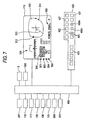
- the screen of the display 415 switches, as shown in Fig. 7, to a simulation screen image in which the bevel shape can be changed.
- An approximate curve value (Bevel curve) obtained from the bevel apex path obtained by the above bevel calculation is displayed on an item 301 "Curve” of an initial screen.
- An approximate curve value (Frame curve) of the frame measured by the unit 2 is displayed on the item 302 "FC”.
- the item 303 "Position” is an item for inputting an offset amount of moving the bevel apex path in parallel to the front or rear surface side of the lens.
- the item 304 "TILT" is an item for inputting the data for tilting the bevel apex path.
- the value of the item 301 "Curve" is obtained, for example, as follows. From arbitrary four points in the path of the bevel apex path obtained by the bevel calculation, it is assumed that the four points are positioned on the spherical surface having the same centers (a, b, c) and radius r.
- n designates refractive index, and in general given 1.523.
- the curve value of the frame (Frame curve) of the item 302 is obtained in the same manner.
- the bevel curve is adjusted to coincide with the frame curve with reference to the curve value displayed in the item 302.
- the adjusting is carried out as follows.
- a highlight cursor 300 (reversingdisplay) displayed by depressing two switches 425 is met to the item 301, and the curve value is changed to a desired value by operating the switches 430a and 430b.
- the highlight cursor 300 is met to the item 303 and the offset value is input.
- the controller 450 obtains, on the basis of the changed input data, a coordinate of a center point of the spherical surface on which the bevel apex stands at the position of the minimum lens edge thickness, and recalculates the bevel apex position on the basis of the radius of the bevel curve obtained based on the coordinate of the center point and the curve value.
- the target lens shape figure 310 based on the frame shape data, a mark 311 showing the position of the minimum lens edge thickness, the mark 312 showing the position of the maximum lens edge thickness, and a rotation cursor 313 designating the radius vector position for showing the bevel forming condition in a bevel cross sectional displaying portion 320 are displayed on the simulation screen.
- the rotation cursor 313 By changing the position of the rotation cursor 313 by the switch of the operation panel 420, the operator can confirm the bevel forming condition planned after processing all over the periphery.
- the operator selects by the switch 427 the beveling grindstone used at the time of beveling. For example, in case the curve value Crv of the bevel is more than 6 (tight) , the grindstone 271 is selected, and in case the curve value Crv of the bevel is less than 6 (moderate), the grindstone 201C is selected.
- the selection information is displayed on the display item 330 on the display 415. When selecting the grindstone 271, "Small” is displayed, and when selecting the grindstone 201c, "Large" is displayed.
- the radius vector information (En, ⁇ n) is rotated around the processing center by a minute arbitrary unit angle, and the maximum value of Lb at such time is demanded.
- the maximum value of Lb at the respective ⁇ i is assumed to be Lbi and ⁇ n at this time of the maximum value of Lb is assumed to be ⁇ i.
- the maximum value of Ls when the radius vector information (En, ⁇ n) is rotated around the processing center by the minute arbitrary unit angle is obtained.
- the maximum value of Ls in the respective ⁇ I is assumed to be Lsi and ⁇ n at the time of the maximum value is assumed to be ⁇ i.
- the start switch 423 is depressed to start the processing.
- the controller 450 controls the operation of the carriage portion 100 in accordance with a processing sequence and executes the processing.
- the carriage base 101 is moved in the X-axial direction by controlling drive of the motor 105 such that the chucked and held lens LE is positionedon the grindstone 201b.
- the carriage base 112 is moved in the Y-axial direction by controlling drive of the motor 135, so that a roughing is executed on the periphery of the lens LE.
- the processing is shifted to the beveling. If the grindstone 271 has been selected, the motor 207 is stopped rotating and the motor 253 is rotated, and the carriage base 101 is moved to the X-axial direction such that the lens LE is positioned on the groove 271a of the grindstone 271.
- the carriage 112 is moved to the Y-axial direction on the basis of the processing information ( ⁇ i, Lsi, ⁇ i) in the Y-axial direction, and the carriage 112 is moved to theX-axial direction on the basis of the bevel apex path data and the correcting information ( ⁇ i, Xsi, ⁇ i) in the X-axial direction, and while rotating the lens LE, the periphery of the lens LE is pressed to the grindstone 271 to perform the beveling.
- the conical grindstone 271 in such a way, even if the bevel curve is tight, it is possible to carry out the process as restraining the bevel from being thin.
- the controller 450 controls the pressing pressure of the lens LE with respect to the grindstone on the basis of the detection of the rotation torque of the motor 135, and controls the moving position in the Y-axial direction of the carriage 112 on the basis of a signal issued from the encoder 136, and judges the processing finish.
- the lens LE is positioned on the groove 202a of the grindstone 201C after finishing the roughing, and the carriage 112 is moved in the Y-axial direction on the basis of the processing information ( ⁇ i, Xsi, ⁇ i) in the Y-axial direction while the carriage 112 is moved in the X-axial direction on the basis of the bevel apex path data to carry out the beveling process by pressing the periphery of the lens LE to the grindstone 201c.
- the process can be carried out by preventing the bevel from being thin by using the cylindrical grindstone 201c.
- the controller 450 may be designed so as to make a determination on the basis of the curve value (this is one of the methods displaying the bevel shape data). That is, similarly to the above example, when the beveled curve value Crv is less than 6, the grindstone 201c is determined to use, and when the bevel curve value Crv is more than 6, the grindstone 271 is determined to use.
- the controller 450 automatically determines the beveling grindstone on the basis of the bevel curve values, at the time of processing a right and left eye lenses, when one curve value Crv is more than 6, and the other curve value Crv is less than 6, it is sufficient to use, for the later processing, the same grindstone used in initial processed processing.
- the shaft 260 is equipped with the chamfering grindstone 272, 273, the grooving grindstone 274 and the drill 280. Therefore, the present apparatus may be also applied to the chamfering of the lens LE, the grooving and the drilling.
- the controller 450 controls the carriage 112 to move in the X- and Y-axial directions on the basis of separately obtained chamfering data.
- the grindstone 272 is controlled to contact the front edge of the lens LE
- the grindstone 273 is controlled to contact the rear edge of the lens LE.
- the controller 450 controls the carriage 112 to move in the X- and Y-axial directions on the basis of the separately obtained grooving data, and the grindstone 274 is pressed to the periphery of the lens LE to carry out the grooving.
- the grooving data can be obtained basically in the similar manner in the processing information of the grindstone 271.
- the drilling position data is input by using the switch of the operation panel 420.
- the drillingposition data is given, for example, at the radius vector length and angle with respect to the rotating center of the lens.
- the controller 450 converts the drilling position data into the data of the X- and Y-axial directions and the lens rotating angle, and positions the front end of the drilling tool 280 to the drilling position of the front surface of the lens. Then, the carriage 112 is controlled to move in the X- and Y-axial directions, such that the lens LE is moved to the tilting angle ⁇ of the shaft 260.
- the second grinding portion 250 in the above embodiment has been explained in the arrangement in the direction opposite to the first grinding portion 200 with respect to the shaft 110L, 110R, and such an arranging structure is also available. That is, when using the first grinding portion 200, the second grinding portion 250 is at a retreating position, and when using the second grinding portion 250, it is moved between the shafts 110L, 110R and the first grinding portion 200.
Abstract
Description
- The present invention is related to an eyeglass lens processing apparatus forprocessingtheperipheryof the eyeglass lenses.
- In the eyeglass lens processing apparatus for processing the lens periphery for fitting the lens into the eyeglass frame, in general, the processing is performed on the lens periphery to form a reverse V-shaped bevel to be fitted into a V-shaped groove in the inside of the frame. This beveling is carried out by a beveling grindstone having a V-shaped beveling groove. The beveling grindstone is ordinarily cylindrical having a diameter of more than 100 mm, in view of consumption, similarly to a roughing grindstone.
- Recently, eyeglass frames have tight curves owing to varieties of designs. However, if the bevel is formed on the lens periphery with using the cylindrical beveling grindstone having the diameter of more than 100 mm so as to coincide with the tight frame curve, the beveling grindstone and the formed bevel interfere each other, and the bevel becomes thin (the bevel width and height become smaller).
- Accordingly, it is a technical object of the invention to provide such an eyeglass lens processing apparatus enabling to form the bevel on the lens periphery so as to coincide with the curve in the eyeglass frame.
- For accomplishing the above-mentioned object, the invention is characterized by providing the under mentioned structures.
- As to the structures of the eyeglass lens processing apparatus of the present invention.
- (1) An eyeglass lens processing apparatus (1) for processing
a periphery of an eyeglass lens (LE), comprising:
- lens rotating means including lens rotating shafts (110L, 110R) for holding the lens;
- first grindingmeans including a first grindstone rotating shaft (203) arranged with a first beveling grindstone for forming a bevel on the periphery of the lens;
- second grinding means including a second grindstone rotating shaft (260) arranged with a second beveling grindstone (271) having a smaller diameter than that of the first beveling grindstone, for forming a bevel on the periphery of the lens; and
- selecting means (420, 450) for selecting either of the first grinding means and the second grinding means when processing the bevel.
- (2) The eyeglass lens processing apparatus according to (1),
further comprising determining means (420, 450) for setting a
shape of the bevel formed on the periphery of the lens,
wherein the selecting means includes determining means for determining either of the first grindingmeans and the second grinding means on the basis of the set bevel shape. - (3) The eyeglass lens processing apparatus according to (1) or (2), wherein the second grindstone rotating shaft has a rotation axis tilting with respect to a rotation axis of the lens rotating shaft.
- (4) The eyeglass lens processing apparatus according to any one of (1) to (3), wherein the second beveling grindstone is a grindstone having a conical shape with a beveling groove.
- (5) The eyeglass lens processing apparatus according to (1)
or (2), wherein the second grindstone rotating shaft has a
rotation axis tilting with respect to a rotation axis of the
lens rotating shaft, and
wherein the second beveling grindstone is a grindstone having a conical shape with a beveling groove, processing faces formed at opposite sides of the beveling groove being parallel with the rotation axis of the lens rotating shaft. - (6) The eyeglass lens processing apparatus according to any
one of (1) to (5), wherein the lens rotating shaft, the first
grindstone rotating shaft and the second grindstone rotating
shaft are arranged such that the respective rotation axes are
positioned on the same plane, and the lens rotating shaft is
arrangedbetween the first and second grindstone rotating shafts,
and
the eyeglass lens processing apparatus further comprises moving means for moving the lens rotating shaft in a direction of changing a distance between the rotation axes with respect to the respective first and second grindstone rotating shafts. - (7) The eyeglass lens processing apparatus according to any
one of (1) to (5), wherein the first grindstone rotating shaft
is coaxially arranged with a roughing grindstones (201a, 201b),
and
wherein the second grindstone rotating shaft is coaxially arranged with at least one of a chamfering grindstone (272, 273), a grooving grindstone (274) and a drilling tool (280). -
-
- Fig. 1 is a schematically external view of the eyeglass lens processing apparatus according to the invention;
- Fig. 2 is a schematic diagram of the lens processing portion;
- Fig. 3 is a schematic diagram of the lens processing portion;
- Fig. 4 is a schematic diagram of the carriage;
- Fig. 5 is a schematic diagram of the second grinding portion;
- Fig. 6 is a schematic diagram of the
measuring portion 2a of the measuring unit 2 of the eyeglasses frame shape; - Fig. 7 is a schematic block diagram of the control system of the present apparatus; and
- Figs. 8A and 8B are views for explaining the method of obtaining the processing information of the beveling grindstone of small diameter.
-
- One embodiment of the invention will be explained on the basis of the attached drawings. Figure 1 is a schematic diagram of the eyeglass lens processing apparatus according to the invention. A main body 1 of the apparatus is connected to an eyeglass frame shape (target lens shape) measuring unit 2. The main body 1 is equipped with a
display 415 for displaying processing information and anoperation panel portion 420 with various switches.Reference number 402 designates an opening window for a processing room. - Figs. 2 and 3 are schematic diagram of a lens processing portion equipped within the main body 1. Fig. 2 is a view seen from the upper part of the processing portion 5. Fig. 3 is a view seen from the right side of the processing portion 5. Incidentally, the main body 1 is provided with a lens shape measuring unit to which known units (described in US Re.35, 898 (Japanese Patent Laid Open No.212661/1993), or EP1310326 A1 (Japanese Patent Laid Open No. 2003-145400)) may be applied, and thus explanation will be omitted.
- A
carriage 100, afirst grinding portion 200 and asecond grinding portion 250 are arranged on abase 10. An eyeglass lens LE to be processed is chucked and held by twolens rotating shafts carriage portion 100, and is subjected to a grinding (edging) on the periphery by the first and second grindingportions - The
first grinding portion 200 is disposed on the front side of thecarriage portion 100, and includes aroughing grindstone 201a for glasses, a roughing grindstone 201b for plastics, and a large diameterbevel finishing grindstone 201c (beveling and flat-edging grindstone) 201c having a V-shapedbeveling groove 202a for beveling (finishing) and aflat processing face 202b for flat-edging (finishing). Thefinishing grindstone 201c may be the beveling grindstone having only thebeveling groove 202a. Thesegrindstones grindstone rotating shaft 203. Theshaft 203 is rotatably pivoted on aspindle unit 205 secured on thebase 10, and is connected at its end to amotor 207. Theshaft 203 is rotated by driving of themotor 207, thereby to rotate thegrindstones grindstones grindstone 201c is used when a path of the bevel to be formed has a comparatively moderate curve (in case a curve value Crv is less than 6). - The
carriage portion 100 includes acarriage base 101 which is movable along tworail shafts 107 extending in a direction of the rotation axis of the shaft 203 (called as "X-axial direction" hereafter) and secured on thebase 10. Arack 103 extending in the X-axial direction is fixed to a rear side of thecarriage base 101, and is connected to apinion 104 mounted on a rotation shaft of apulse motor 105 secured on thebase 10. Therack 103 is moved by driving themotor 105, so that thecarriage base 101 is moved in the X-axial direction. - A
carriage 112 having approximately U-shape seen from a front side is mounted on thecarriage base 101. Fig. 4 is a schematic diagram of thecarriage 112 seen from the front side. Thecarriage 112 is provided with an upward extendingleft arm 112L andright arm 112R, theleft arm 112L holding theshaft 110L and theright arm 112R holding theshaft 110R, and bothshafts shaft 110R is movable in the direction of the rotation axis (X-axial direction) by themotor 115 fixed to the right side of thecarriage 112 and by amoving mechanism 116 such as a feed screw provided inside of theright arm 112R, so that the lens LE is chucked and held by theshafts shaft 120 extending in the X-axial direction and disposed within thecarriage 112 is connected to the rotating shaft of themotor 117 fixed to the right side of thecarriage 112. Theshaft 120 is connected to theshaft 110L via abelt 121 and also to theshaft 110R via abelt 122. Theshaft 120 is rotated by driving of themotor 117, so that theshafts - The
carriage base 101 is secured with tworail shafts 131 extending in parallel in a direction of changing a distance between the rotation axis of theshaft 203 and the rotation axes of theshafts carriage base 101 also tilts toward this side (see Figure 3). Thecarriage 112 is displaced movably in the Y-axial direction along theshafts 131. Themotor 135 is fixed to a rear side of thecarriage base 101, and is connected, on its rotating shaft, to afeed screw 133 extending in the Y-axial direction. Thescrew 133 is rotated by driving of themotor 135, so that thecarriage 112 is moved in the Y-axial direction. For themotor 135, a servomotor provided with anencoder 136 for detecting rotation is employed. During processing, rotation torque (motor load current) ofthemotor 135 is detected, and voltage supplied to themotor 135 is controlled on the basis of detected results, so that a processing pressure of the lens LE to the grindstone is controlled. Position information of moving thecarriage 112 is detected on the basis of a signal issued from theencoder 136, and the processing finish is judged. - The
second grinding portion 250 is secured on thebase 10 via an attachingmember 201 so as to be positioned at the inner part of thecarriage portion 100. Fig. 5 is a schematic diagram of the second grindingportion 250. Thesecond grinding portion 250 is provided with amotor 253, an L-shapedsupport 257 rotatably supporting arotating shaft 255 connected to themotor 253 and agrindstone rotating shaft 260, a grindingportion 270 and adrilling tool 280 disposed (attached) to theshaft 260. The rotation of theshaft 255 by driving of themotor 253 is transmitted to theshaft 260 viabevel gears portion 270 and thedrilling tool 280 are rotated. - The rotation axis of the
shaft 260, the rotation axes of theshafts shaft 203 are arranged to be positioned on the same plane 01 (see Fig. 3). The rotation axis of theshaft 260 tilt with respect to the rotation axes of theshafts - The grinding
portion 270 is provided with a small diameter conically shapedbeveling grindstone 271 having a V-shapedbeveling groove 271a, achamfering grindstone 272 for a lens front surface, achamfering grindstone 273 for a lens rear surface, and agrooving grindstone 274. Thegrindstone 271 is smaller in diameter than thegrindstone 201c, desirably less than half of thegrindstone 201c. Thereby, the bevel can be restrained from becoming thin, even if the path of the bevel to be formed has a comparatively tight curve (in case the curve value Crv is more than 6). In the present embodiment, the diameter of the grindstone 271 (the smallest diameter of thegroove 271a) is approximately 30 mm. An angle (angle with respect to the rotation axis of the shaft 260) of a conical shaped processed face (processing faces at both outsides of thegroove 271a) of thegrindstone 271 is the same as the tilting angle α of theshaft 260. Therefore, the processing face of thegrindstone 271 is parallel with the direction of the rotation axes of theshafts grindstones grindstone 271. The largest outer diameter of thegrindstone 274 is positioned somewhat inside than the extension of the processing face of thegrindstone 271. Thedrilling tool 280 is coaxial with the shaft 260 (the respective rotation axes are coaxial), and is disposed (attached) at the end part thereof. - By the way, it is sufficient that the
shaft 260 is not tilted and kept parallel with the direction of the rotation axes of theshafts shaft 260 is preferably tilted. - The
carriage 112 is movable in the Y-axial direction for forcing the lens LE chucked and held by theshafts portion 270, and the distance between the rotation axes of theshafts shaft 203 is changed by controlling driving of themotor 135. - Figure 6 is a schematic diagram of a measuring
portion 2a of the eyeglasses frame shape measuring unit 2. The measuringportion 2a includes: afirst base 21 movable horizontally; asecond base 22 to be rotated by apulse motor 30 fixed to thefirst base 21; holdingplates second base 22; a movingblock 37 movable along twoshafts plates gauge shaft 23 passing through the movingblock 37 and being rotatable and vertically movable; agauge head 24 provided at the upper end of thegauge shaft 23, the distal end of thegauge head 24 being on the axis of thegauge shaft 23; anarm 41 rotatably attached to the lower end of thegauge shaft 23 and fixed to apin 42 vertically extending from the movingblock 37; a shieldingplate 25 provided to the front end of thearm 41 and formed with avertical slit 26 and aslit 27 tilting 45 degrees with respect to thevertical slit 26; a pair oflight emitting diode 28 andlinear image sensor 29 provided on thesecond base 22 as holding the shieldingplate 25 therebetween; and aconstant torque spring 43 attached on adrum 44 rotatably pivoted on thesecond base 22 and always pulling the movingblock 37 to the front end side of thegauge head 24. - With such constructed measuring
portion 2a, the shape of the eyeglass frame is measured as described hereinafter. At first, the frame is held and secured to a frame holding portion (not shown, see US Re.35,898 (Japanese Patent Laid Open No.212,661/1993)), and thegauge head 24 is contacted at its front end to the inside groove of the frame. Subsequently, themotor 30 is rotated per each of pulse numbers of predetermined unit rotation. At this time, thegauge shaft 23 integrally with thegauge head 24 move along theshafts plate 25 moves vertically and laterally between thelight emitting diode 28 and thelinear image sensor 29, and cuts off the light from thelight emitting diode 28. The light passing through theslits plate 25 reaches a light reception part of thelinear image sensor 29, and a moving amount thereof is read out. The moving amount is read out in a manner that the position of theslit 26 is the radius vector r of the frame, and the difference in position between theslit 26 and theslit 27 is read out as a height z of the frame. By measuring N points in this manner, the shapes of the frames are measured as (rn, n, zn) (n = 1, 2, ... N) (as to details, see US Patent No.5,138,770 (Japanese Patent Laid Open No.105864/ 1992). - In the apparatus having the above mentioned structure, the operation thereof will be explained with reference to a schematic block diagram of the control system in Fig. 7. At first, the frame shape is measured by the unit 2. The data (rn, n, zn) of the frame shape are input and stored in the
data memory 451 by depressing aswitch 421 of theoperation panel portion 420. A target lens shape figure 310 based on the frame shape data is displayed on thedisplay 415, and processing conditions is ready for being set or input. An operator inputs the processing conditions such as layout data including PD value and FPD value of a wearer of the eyeglass and height of an optical center, material of the lens to be processed, material of the frame, processing mode, and the like. Herein, assuming that the lens LE is processed to coincide with the frame of tight curve, the processing mode is set to a bevel forcing mode by themode switch 422. When the processing condition is inputted, the lens LE is chucked and held by theshafts start switch 423 is depressed to activate the apparatus. - The
controller 450 activates the lensshape measuring portion 500 by a start signal, and measures a position of an edge of the lens LE corresponding to the frame shape data and the layout data. Then, thecontroller 450 carries out a bevel calculation for obtaining a path of an apex of the bevel to be formed on the periphery of the lens LE on the basis of the edge position information according to a predetermined program. The bevel apex path is one of methods for representing the bevel shape data. The bevel calculation at this stage divides, for example, the lens edge thickness with a predetermined ratio (for example, 3 : 7 from the front surface side of the lens), and positions the bevel apexes on the full radius vector periphery. - When finishing the bevel calculation, the screen of the
display 415 switches, as shown in Fig. 7, to a simulation screen image in which the bevel shape can be changed. An approximate curve value (Bevel curve) obtained from the bevel apex path obtained by the above bevel calculation is displayed on anitem 301 "Curve" of an initial screen. An approximate curve value (Frame curve) of the frame measured by the unit 2 is displayed on theitem 302 "FC". Theitem 303 "Position" is an item for inputting an offset amount of moving the bevel apex path in parallel to the front or rear surface side of the lens. Theitem 304 "TILT" is an item for inputting the data for tilting the bevel apex path. - The value of the
item 301 "Curve" is obtained, for example, as follows. From arbitrary four points in the path of the bevel apex path obtained by the bevel calculation, it is assumed that the four points are positioned on the spherical surface having the same centers (a, b, c) and radius r. - An equation of the spherical surface is
- By substituting the arbitrary four points of the bevel apex position into this equation, the centers (a, b, c) and radius r of the spherical surface passing through the four points are obtained respectively. This calculation is carried out to make several couples of the calculation (4 or 5 couples) for getting an average. The curve value Crv is determined based on the obtained radius r of the lens. The curve value Crv customarily expresses the lens curve in the eyeglass lens, and is obtained by the following equation.
- In this equation, n designates refractive index, and in general given 1.523. The curve value of the frame (Frame curve) of the
item 302 is obtained in the same manner. - Herein, if difference between the bevel curve and the frame curve is too large, the lens cannot be fitted into the frame, and in such a case, the bevel curve is adjusted to coincide with the frame curve with reference to the curve value displayed in the
item 302. The adjusting is carried out as follows. A highlight cursor 300 (reversingdisplay) displayed by depressing twoswitches 425 is met to theitem 301, and the curve value is changed to a desired value by operating theswitches highlight cursor 300 is met to theitem 303 and the offset value is input. Thecontroller 450 obtains, on the basis of the changed input data, a coordinate of a center point of the spherical surface on which the bevel apex stands at the position of the minimum lens edge thickness, and recalculates the bevel apex position on the basis of the radius of the bevel curve obtained based on the coordinate of the center point and the curve value. - Incidentally, the target lens shape figure 310 based on the frame shape data, a
mark 311 showing the position of the minimum lens edge thickness, themark 312 showing the position of the maximum lens edge thickness, and arotation cursor 313 designating the radius vector position for showing the bevel forming condition in a bevel crosssectional displaying portion 320 are displayed on the simulation screen. By changing the position of therotation cursor 313 by the switch of theoperation panel 420, the operator can confirm the bevel forming condition planned after processing all over the periphery. - Based on whether the bevel curve set at the
item 301 is tight or moderate, the operator selects by theswitch 427 the beveling grindstone used at the time of beveling. For example, in case the curve value Crv of the bevel is more than 6 (tight) , thegrindstone 271 is selected, and in case the curve value Crv of the bevel is less than 6 (moderate), the grindstone 201C is selected. The selection information is displayed on thedisplay item 330 on thedisplay 415. When selecting thegrindstone 271, "Small" is displayed, and when selecting thegrindstone 201c, "Large" is displayed. - The
controller 450 obtains the processing information for beveling in response to the selection of the beveling grindstone. Calculation of the processing information will be explained. At first, in case of thecylindrical grindstone 201c, the processing information is obtained as follows. It is assumed that the radius vector information of the bevel apex path is (En, n) (n = 1, 2, ...N). En is the radius vector length (radius), and n is the radius vector angle. Further, the radius of thegroove 202a in thegrindstone 201c is assumed to be Rb. At this time, the axis-to-axis distance Lb between the rotation center (rotation axis) of thegrindstone 201c and the processing center (rotational axis) of the lens LE (the distance between the rotation axis of theshaft 203 and the rotation axes of theshafts - Herein, the radius vector information (En, n) is rotated around the processing center by a minute arbitrary unit angle, and the maximum value of Lb at such time is demanded. This rotating angle is assumed to be ξi (i = 1, 2, 3, ... N). The maximum value of Lb at the respective ξi is assumed to be Lbi and n at this time of the maximum value of Lb is assumed to be Θi. Byperforming the calculation all over the full periphery, the processing information in the direction of the axis-to-axis distance (Y-axial direction) is obtained as (ξi, Lbi, Θi)(i = 1, 2, 3, ... N).
- In case of the
grindstone 271, since theshaft 260 is not parallel to theshafts shafts groove 271a in thegrindstone 271 is assumed to be Rs, the axis-to-axis distance Ls between the rotating center (the rotation axis) of thegrindstone 271 and the processing center (rotation axis) of the lens LE (the distance is between the rotation axis of theshaft 260 and the rotation axes of theshafts - Similarly to the above mentioned, the maximum value of Ls when the radius vector information (En, n) is rotated around the processing center by the minute arbitrary unit angle is obtained. This rotating angle is assumed to be ξi (i = 1, 2, 3, ... N) . The maximum value of Ls in the respective ξI is assumed to be Lsi and n at the time of the maximum value is assumed to be Θi. By performing this calculation all over the full periphery, the processing information in the direction of the axis-to-axis distance (Y-axial direction) is obtained as (ξi, Lbi, Θi) (i = 1, 2, 3, ... N).
- Since the
shaft 260 tilts, when seeing the grindstone shape from the side of the lens LE, it is oval as shown in Figure 8B. Therefore, using thegrindstone 271, the direction of the rotation axes axial of theshafts - Similarly to the above mentioned, the radius vector information (En, n) is rotated around the processing center by the minute arbitrary unit angle, and the maximum value of Xs at such time is obtained, whereby it is obtained as the correcting information in the X-axial direction (ξi, Lsi, Θi) (i = 1, 2, 3, ... N).
- After confirming the bevel forming condition through the bevel cross
sectional displaying portion 320, if there is no problem, thestart switch 423 is depressed to start the processing. Thecontroller 450 controls the operation of thecarriage portion 100 in accordance with a processing sequence and executes the processing. In the case that the material of the lens LE is plastic, thecarriage base 101 is moved in the X-axial direction by controlling drive of themotor 105 such that the chucked and held lens LE is positionedon the grindstone 201b. Subsequently, thecarriage base 112 is moved in the Y-axial direction by controlling drive of themotor 135, so that a roughing is executed on the periphery of the lens LE. - Finishing the roughing, the processing is shifted to the beveling. If the
grindstone 271 has been selected, themotor 207 is stopped rotating and themotor 253 is rotated, and thecarriage base 101 is moved to the X-axial direction such that the lens LE is positioned on thegroove 271a of thegrindstone 271. Then, thecarriage 112 is moved to the Y-axial direction on the basis of the processing information (ξi, Lsi, Θi) in the Y-axial direction, and thecarriage 112 is moved to theX-axial direction on the basis of the bevel apex path data and the correcting information (ξi, Xsi, Θi) in the X-axial direction, and while rotating the lens LE, the periphery of the lens LE is pressed to thegrindstone 271 to perform the beveling. Using theconical grindstone 271 in such a way, even if the bevel curve is tight, it is possible to carry out the process as restraining the bevel from being thin. - Incidentally, at the time of processing the lens LE, the
controller 450 controls the pressing pressure of the lens LE with respect to the grindstone on the basis of the detection of the rotation torque of themotor 135, and controls the moving position in the Y-axial direction of thecarriage 112 on the basis of a signal issued from theencoder 136, and judges the processing finish. - When the
grindstone 201c has been selected, the lens LE is positioned on thegroove 202a of the grindstone 201C after finishing the roughing, and thecarriage 112 is moved in the Y-axial direction on the basis of the processing information (ξi, Xsi, Θi) in the Y-axial direction while thecarriage 112 is moved in the X-axial direction on the basis of the bevel apex path data to carry out the beveling process by pressing the periphery of the lens LE to thegrindstone 201c. If dealing with all the beveling with only theconical grindstone 271, in case the beveled curve is contrary moderate, the bevel becomes thin due to the interference. Therefore, in the case that the beveled curve is moderate, the process can be carried out by preventing the bevel from being thin by using thecylindrical grindstone 201c. - Although, in the above description, the beveling grindstone is selected by the operator depressing the
switch 427, thecontroller 450 may be designed so as to make a determination on the basis of the curve value (this is one of the methods displaying the bevel shape data). That is, similarly to the above example, when the beveled curve value Crv is less than 6, thegrindstone 201c is determined to use, and when the bevel curve value Crv is more than 6, thegrindstone 271 is determined to use. Incidentally, as to the control in which thecontroller 450 automatically determines the beveling grindstone on the basis of the bevel curve values, at the time of processing a right and left eye lenses, when one curve value Crv is more than 6, and the other curve value Crv is less than 6, it is sufficient to use, for the later processing, the same grindstone used in initial processed processing. - In the present apparatus, the
shaft 260 is equipped with thechamfering grindstone grindstone 274 and thedrill 280. Therefore, the present apparatus may be also applied to the chamfering of the lens LE, the grooving and the drilling. - In case that the chamfering has been selected by the switch of the
operation panel 420, thecontroller 450 controls thecarriage 112 to move in the X- and Y-axial directions on the basis of separately obtained chamfering data. For chamfering the front surface, thegrindstone 272 is controlled to contact the front edge of the lens LE, while for chamfering the lens rear surface, thegrindstone 273 is controlled to contact the rear edge of the lens LE. - In case the processing mode is set to the grooving mode, after the roughing and the flat-edging, the
controller 450 controls thecarriage 112 to move in the X- and Y-axial directions on the basis of the separately obtained grooving data, and thegrindstone 274 is pressed to the periphery of the lens LE to carry out the grooving. The grooving data can be obtained basically in the similar manner in the processing information of thegrindstone 271. - In case that the processing mode is set to the drilling mode, the drilling position data is input by using the switch of the
operation panel 420. The drillingposition data is given, for example, at the radius vector length and angle with respect to the rotating center of the lens. Thecontroller 450 converts the drilling position data into the data of the X- and Y-axial directions and the lens rotating angle, and positions the front end of thedrilling tool 280 to the drilling position of the front surface of the lens. Then, thecarriage 112 is controlled to move in the X- and Y-axial directions, such that the lens LE is moved to the tilting angle α of theshaft 260. - The
second grinding portion 250 in the above embodiment has been explained in the arrangement in the direction opposite to the first grindingportion 200 with respect to theshaft portion 200, the second grindingportion 250 is at a retreating position, and when using the second grindingportion 250, it is moved between theshafts portion 200. - Further, by providing a third beveling grindstone having an intermediate diameter set between the diameter of the small
diameter beveling grindstone 271 and the diameter of the largediameter beveling grindstone 271, it is possible to restrain the bevel from being thin with respect to an intermediate bevel curve of the curve value Crv being 4 to 6. In this case, for the structures shown in Figures 2 and 3, it is sufficient to move the third beveling grindstone from the retreating position to the using position.
Claims (7)
- An eyeglass lens processing apparatus (1) for processing a periphery of an eyeglass lens (LE), comprising:lens rotating means including lens rotating shafts (110L, 110R) for holding the lens;first grinding means including a first grindstone rotating shaft (203) arranged withafirstbeveling grindstone for forming a bevel on the periphery of the lens;second grinding means including a second grindstone rotating shaft (260) arranged with a second beveling grindstone (271) having a smaller diameter than that of the first beveling grindstone, for forming a bevel on the periphery of the lens; andselecting means (420, 450) for selecting either of the first grinding means and the second grinding means when processing the bevel.
- The eyeglass lens processing apparatus according to claim 1, further comprising determining means (420, 450) for setting a shape of the bevel formed on the periphery of the lens,
wherein the selecting means includes determining means for determining either of the first grinding means and the second grinding means on the basis of the set bevel shape. - The eyeglass lens processing apparatus according to claim 1 or 2, wherein the second grindstone rotating shaft has a rotation axis tilting with respect to a rotation axis of the lens rotating shaft.
- The eyeglass lens processing apparatus according to any one of claims 1 to 3, wherein the second beveling grindstone is a grindstone having a conical shape with a beveling groove.
- The eyeglass lens processing apparatus according to claim 1 or 2, wherein the second grindstone rotating shaft has a rotation axis tilting with respect to a rotation axis of the lens rotating shaft, and
wherein the second beveling grindstone is a grindstone having a conical shape with a beveling groove, processing faces formed at opposite sides of the beveling groove being parallel with the rotation axis of the lens rotating shaft. - The eyeglass lens processing apparatus according to any one of claims 1 to 5, wherein the lens rotating shaft, the first grindstone rotating shaft and the second grindstone rotating shaft are arranged such that the respective rotation axes are positioned on the same plane, and the lens rotating shaft is arranged between the first and second grindstone rotating shafts, and
the eyeglass lens processing apparatus further comprises moving means for moving the lens rotating shaft in a direction of changing a distance between the rotation axes with respect to the respective first and second grindstone rotating shafts. - The eyeglass lens processing apparatus according to any one of claims 1 to 5, wherein the first grindstone rotating shaft is coaxially arranged with a roughing grindstones (201a, 201b), and
wherein the second grindstone rotating shaft is coaxially arranged with at least one of a chamfering grindstone (272, 273), a grooving grindstone (274) and a drilling tool (280).
Applications Claiming Priority (2)
| Application Number | Priority Date | Filing Date | Title |
|---|---|---|---|
| JP2003307761A JP4131842B2 (en) | 2003-08-29 | 2003-08-29 | Eyeglass lens processing equipment |
| JP2003307761 | 2003-08-29 |
Publications (2)
| Publication Number | Publication Date |
|---|---|
| EP1510290A1 true EP1510290A1 (en) | 2005-03-02 |
| EP1510290B1 EP1510290B1 (en) | 2007-10-10 |
Family
ID=34101267
Family Applications (1)
| Application Number | Title | Priority Date | Filing Date |
|---|---|---|---|
| EP20040020466 Expired - Fee Related EP1510290B1 (en) | 2003-08-29 | 2004-08-27 | Eyeglass lens processing apparatus |
Country Status (4)
| Country | Link |
|---|---|
| EP (1) | EP1510290B1 (en) |
| JP (1) | JP4131842B2 (en) |
| DE (1) | DE602004009374T2 (en) |
| ES (1) | ES2294413T3 (en) |
Cited By (9)
| Publication number | Priority date | Publication date | Assignee | Title |
|---|---|---|---|---|
| EP1588818A1 (en) * | 2004-04-20 | 2005-10-26 | INDO Internacional, S.A. | Numeric control bore for boring an eyeglass lens and corresponding method |
| FR2893524A1 (en) * | 2005-11-24 | 2007-05-25 | Essilor Int | Ophthalmic lens trimming method for spectacle frame, involves dynamically moving two axes of rotation relative to each other so that tangent to curve of machining portion of grinding wheel edge is parallel to tangent to curve of lens bevel |
| EP1974855A1 (en) * | 2007-03-28 | 2008-10-01 | Nidek Co., Ltd. | Eyelass lens processing apparatus |
| US7476143B2 (en) | 2006-01-05 | 2009-01-13 | Nidek Co., Ltd. | Eyeglass lens processing system |
| FR2921285A1 (en) * | 2007-09-24 | 2009-03-27 | Essilor Int | Ophthalmic lens trimming method, involves carrying out edge retrieving process by machining rear foot on portion of surface of foot using grinding wheel whose work generator is inclined with respect to blocking axis |
| US7540798B2 (en) | 2006-05-31 | 2009-06-02 | Nidek Co., Ltd. | Eyeglass lens processing apparatus |
| EP2065129A2 (en) | 2007-11-30 | 2009-06-03 | Nidek Co., Ltd. | Eyeglass lens processing apparatus |
| EP2275229A2 (en) | 2009-07-08 | 2011-01-19 | Nidek co., Ltd. | Eyeglass lens processing apparatus |
| CN103302567A (en) * | 2012-03-09 | 2013-09-18 | 尼德克株式会社 | Eyeglass lens processing apparatus |
Families Citing this family (9)
| Publication number | Priority date | Publication date | Assignee | Title |
|---|---|---|---|---|
| JP4368693B2 (en) * | 2004-01-29 | 2009-11-18 | 株式会社トプコン | Lens grinding method and apparatus |
| JP4873878B2 (en) * | 2005-03-31 | 2012-02-08 | 株式会社ニデック | Eyeglass lens peripheral processing equipment |
| JP4800784B2 (en) * | 2006-02-14 | 2011-10-26 | Hoya株式会社 | Spectacle lens processing apparatus and spectacle lens |
| FR2900854B1 (en) * | 2006-05-10 | 2009-07-17 | Essilor Int | METHOD AND DEVICE FOR SOURCEING A LENS BY CUTTING THE LENS |
| FR2904703B1 (en) * | 2006-08-04 | 2008-12-12 | Essilor Int | PAIR OF OPHTHALMIC GLASSES AND METHOD OF FORMING A PERIPHERAL RIB OF EMBOITEMENT ON THE SINGING OF A LENS |
| JP5073345B2 (en) | 2007-03-30 | 2012-11-14 | 株式会社ニデック | Eyeglass lens processing equipment |
| JP5405720B2 (en) * | 2007-03-30 | 2014-02-05 | 株式会社ニデック | Eyeglass lens processing equipment |
| JP6197260B2 (en) * | 2013-08-07 | 2017-09-20 | 波田野 義行 | Eyeglass lens processing equipment |
| JP6388416B2 (en) * | 2017-05-04 | 2018-09-12 | 波田野 義行 | Eyeglass lens processing equipment |
Citations (3)
| Publication number | Priority date | Publication date | Assignee | Title |
|---|---|---|---|---|
| EP0857540A2 (en) * | 1997-02-10 | 1998-08-12 | Nidek Co., Ltd. | Lens grinding apparatus |
| EP1155775A2 (en) * | 2000-04-28 | 2001-11-21 | Nidek Co., Ltd. | Eyeglass lens processing apparatus |
| EP1310326A1 (en) * | 2001-11-08 | 2003-05-14 | Nidek Co., Ltd. | Eyeglass lens processing apparatus |
Family Cites Families (6)
| Publication number | Priority date | Publication date | Assignee | Title |
|---|---|---|---|---|
| JP2582788B2 (en) * | 1987-07-02 | 1997-02-19 | 株式会社トプコン | Gazuri machine |
| JP3602303B2 (en) * | 1997-08-01 | 2004-12-15 | 株式会社ニデック | Eyeglass lens grinding machine |
| JP3892182B2 (en) * | 1998-10-06 | 2007-03-14 | Hoya株式会社 | End face processing method of eyeglass lens |
| JP3895075B2 (en) * | 1999-08-06 | 2007-03-22 | Hoya株式会社 | Lens holder |
| JP2001212740A (en) * | 2000-02-02 | 2001-08-07 | Shigiya Machinery Works Ltd | Spectacle lens machining method and its device |
| JP4271418B2 (en) * | 2002-08-16 | 2009-06-03 | 株式会社トプコン | Eyeglass lens grinding machine |
-
2003
- 2003-08-29 JP JP2003307761A patent/JP4131842B2/en not_active Expired - Fee Related
-
2004
- 2004-08-27 ES ES04020466T patent/ES2294413T3/en active Active
- 2004-08-27 EP EP20040020466 patent/EP1510290B1/en not_active Expired - Fee Related
- 2004-08-27 DE DE200460009374 patent/DE602004009374T2/en active Active
Patent Citations (3)
| Publication number | Priority date | Publication date | Assignee | Title |
|---|---|---|---|---|
| EP0857540A2 (en) * | 1997-02-10 | 1998-08-12 | Nidek Co., Ltd. | Lens grinding apparatus |
| EP1155775A2 (en) * | 2000-04-28 | 2001-11-21 | Nidek Co., Ltd. | Eyeglass lens processing apparatus |
| EP1310326A1 (en) * | 2001-11-08 | 2003-05-14 | Nidek Co., Ltd. | Eyeglass lens processing apparatus |
Cited By (19)
| Publication number | Priority date | Publication date | Assignee | Title |
|---|---|---|---|---|
| US7334313B2 (en) | 2004-04-20 | 2008-02-26 | Indo Internacional, S.A. | Numeric control bore for boring an eyeglass lens and corresponding method |
| EP1588818A1 (en) * | 2004-04-20 | 2005-10-26 | INDO Internacional, S.A. | Numeric control bore for boring an eyeglass lens and corresponding method |
| FR2893524A1 (en) * | 2005-11-24 | 2007-05-25 | Essilor Int | Ophthalmic lens trimming method for spectacle frame, involves dynamically moving two axes of rotation relative to each other so that tangent to curve of machining portion of grinding wheel edge is parallel to tangent to curve of lens bevel |
| WO2007060329A1 (en) * | 2005-11-24 | 2007-05-31 | Essilor International (Compagnie Générale d'Optique) | Method and device for trimming an ophthalmic lens in order to machine the edge of the lens along a desired curve |
| US8167680B2 (en) | 2005-11-24 | 2012-05-01 | Essilor International (Compagnie Generale D'optique) | Method and a device for edging an ophthalmic lens for machining the edge face of the lens to a desired curve |
| US7476143B2 (en) | 2006-01-05 | 2009-01-13 | Nidek Co., Ltd. | Eyeglass lens processing system |
| US7540798B2 (en) | 2006-05-31 | 2009-06-02 | Nidek Co., Ltd. | Eyeglass lens processing apparatus |
| EP1974855A1 (en) * | 2007-03-28 | 2008-10-01 | Nidek Co., Ltd. | Eyelass lens processing apparatus |
| US7848843B2 (en) | 2007-03-28 | 2010-12-07 | Nidek Co., Ltd. | Eyeglass lens processing apparatus and lens fixing cup |
| WO2009071771A3 (en) * | 2007-09-24 | 2009-08-13 | Essilor Int | Device for correcting the edging of an ophthalmic lens and method for edging an ophthalmic lens |
| FR2921285A1 (en) * | 2007-09-24 | 2009-03-27 | Essilor Int | Ophthalmic lens trimming method, involves carrying out edge retrieving process by machining rear foot on portion of surface of foot using grinding wheel whose work generator is inclined with respect to blocking axis |
| EP2065129A2 (en) | 2007-11-30 | 2009-06-03 | Nidek Co., Ltd. | Eyeglass lens processing apparatus |
| US8235770B2 (en) | 2007-11-30 | 2012-08-07 | Nidek Co., Ltd. | Eyeglass lens processing apparatus |
| EP2065129A3 (en) * | 2007-11-30 | 2013-04-24 | Nidek Co., Ltd. | Eyeglass lens processing apparatus |
| EP2275229A2 (en) | 2009-07-08 | 2011-01-19 | Nidek co., Ltd. | Eyeglass lens processing apparatus |
| US8684795B2 (en) | 2009-07-08 | 2014-04-01 | Nidek Co., Ltd. | Eyeglass lens processing apparatus |
| CN103302567A (en) * | 2012-03-09 | 2013-09-18 | 尼德克株式会社 | Eyeglass lens processing apparatus |
| EP2636484A3 (en) * | 2012-03-09 | 2014-11-12 | Nidek Co., Ltd | Eyeglass lens processing apparatus |
| US9776293B2 (en) | 2012-03-09 | 2017-10-03 | Nidek Co., Ltd. | Eyeglass lens processing apparatus |
Also Published As
| Publication number | Publication date |
|---|---|
| ES2294413T3 (en) | 2008-04-01 |
| EP1510290B1 (en) | 2007-10-10 |
| DE602004009374T2 (en) | 2008-07-10 |
| DE602004009374D1 (en) | 2007-11-22 |
| JP4131842B2 (en) | 2008-08-13 |
| JP2005074560A (en) | 2005-03-24 |
Similar Documents
| Publication | Publication Date | Title |
|---|---|---|
| EP1510290B1 (en) | Eyeglass lens processing apparatus | |
| US7322082B2 (en) | Eyeglass lens processing apparatus | |
| US6942542B2 (en) | Eyeglass lens processing apparatus | |
| US6790124B2 (en) | Eyeglass lens processing apparatus | |
| US8235770B2 (en) | Eyeglass lens processing apparatus | |
| EP1974857B1 (en) | Eyeglass lens processing apparatus | |
| US7507142B2 (en) | Eyeglass lens processing apparatus | |
| KR101516434B1 (en) | Apparatus for processing eyeglass lens | |
| EP1938923B1 (en) | Method of grinding eyeglass lens, and eyeglass lens grinding apparatus | |
| US7840294B2 (en) | Layout setting device for processing eyeglass lens, eyeglass lens processing apparatus, eyeglass frame measuring device and cup attaching device, each having the same | |
| EP2191935B1 (en) | Eyeglass lens processing apparatus for processing periphery of eyeglass lens | |
| JP5301823B2 (en) | Eyeglass lens peripheral processing equipment | |
| EP1815941B1 (en) | Eyeglass lens processing apparatus | |
| JP2007181889A (en) | Glass lens working system | |
| EP0960690B1 (en) | Eyeglass lens grinding apparatus | |
| JP2008254078A (en) | Spectacle lens machining device | |
| JP5209358B2 (en) | Bend locus setting method and spectacle lens processing apparatus | |
| JP5265127B2 (en) | Eyeglass lens processing equipment | |
| US6641460B2 (en) | Lens grinding apparatus | |
| US6220927B1 (en) | Lens grinding apparatus | |
| KR101437160B1 (en) | Eyeglass lens processing apparatus | |
| US6048258A (en) | Apparatus for grinding eyeglass lens |
Legal Events
| Date | Code | Title | Description |
|---|---|---|---|
| PUAI | Public reference made under article 153(3) epc to a published international application that has entered the european phase |
Free format text: ORIGINAL CODE: 0009012 |
|
| AK | Designated contracting states |
Kind code of ref document: A1 Designated state(s): AT BE BG CH CY CZ DE DK EE ES FI FR GB GR HU IE IT LI LU MC NL PL PT RO SE SI SK TR |
|
| AX | Request for extension of the european patent |
Extension state: AL HR LT LV MK |
|
| 17P | Request for examination filed |
Effective date: 20050726 |
|
| AKX | Designation fees paid |
Designated state(s): DE ES FR GB |
|
| GRAP | Despatch of communication of intention to grant a patent |
Free format text: ORIGINAL CODE: EPIDOSNIGR1 |
|
| GRAS | Grant fee paid |
Free format text: ORIGINAL CODE: EPIDOSNIGR3 |
|
| GRAA | (expected) grant |
Free format text: ORIGINAL CODE: 0009210 |
|
| AK | Designated contracting states |
Kind code of ref document: B1 Designated state(s): DE ES FR GB |
|
| REG | Reference to a national code |
Ref country code: GB Ref legal event code: FG4D |
|
| REF | Corresponds to: |
Ref document number: 602004009374 Country of ref document: DE Date of ref document: 20071122 Kind code of ref document: P |
|
| ET | Fr: translation filed | ||
| REG | Reference to a national code |
Ref country code: ES Ref legal event code: FG2A Ref document number: 2294413 Country of ref document: ES Kind code of ref document: T3 |
|
| PLBE | No opposition filed within time limit |
Free format text: ORIGINAL CODE: 0009261 |
|
| STAA | Information on the status of an ep patent application or granted ep patent |
Free format text: STATUS: NO OPPOSITION FILED WITHIN TIME LIMIT |
|
| 26N | No opposition filed |
Effective date: 20080711 |
|
| PGFP | Annual fee paid to national office [announced via postgrant information from national office to epo] |
Ref country code: ES Payment date: 20120827 Year of fee payment: 9 Ref country code: DE Payment date: 20120822 Year of fee payment: 9 |
|
| PG25 | Lapsed in a contracting state [announced via postgrant information from national office to epo] |
Ref country code: DE Free format text: LAPSE BECAUSE OF NON-PAYMENT OF DUE FEES Effective date: 20140301 |
|
| REG | Reference to a national code |
Ref country code: DE Ref legal event code: R119 Ref document number: 602004009374 Country of ref document: DE Effective date: 20140301 |
|
| REG | Reference to a national code |
Ref country code: ES Ref legal event code: FD2A Effective date: 20140908 |
|
| PG25 | Lapsed in a contracting state [announced via postgrant information from national office to epo] |
Ref country code: ES Free format text: LAPSE BECAUSE OF NON-PAYMENT OF DUE FEES Effective date: 20130828 |
|
| REG | Reference to a national code |
Ref country code: FR Ref legal event code: PLFP Year of fee payment: 13 |
|
| PGFP | Annual fee paid to national office [announced via postgrant information from national office to epo] |
Ref country code: GB Payment date: 20160824 Year of fee payment: 13 |
|
| REG | Reference to a national code |
Ref country code: FR Ref legal event code: PLFP Year of fee payment: 14 |
|
| PGFP | Annual fee paid to national office [announced via postgrant information from national office to epo] |
Ref country code: FR Payment date: 20170714 Year of fee payment: 14 |
|
| GBPC | Gb: european patent ceased through non-payment of renewal fee |
Effective date: 20170827 |
|
| PG25 | Lapsed in a contracting state [announced via postgrant information from national office to epo] |
Ref country code: GB Free format text: LAPSE BECAUSE OF NON-PAYMENT OF DUE FEES Effective date: 20170827 |
|
| PG25 | Lapsed in a contracting state [announced via postgrant information from national office to epo] |
Ref country code: FR Free format text: LAPSE BECAUSE OF NON-PAYMENT OF DUE FEES Effective date: 20180831 |