EP1510143B1 - Hockey helmet comprising an occipital adjustement mechanism - Google Patents
Hockey helmet comprising an occipital adjustement mechanism Download PDFInfo
- Publication number
- EP1510143B1 EP1510143B1 EP03292840A EP03292840A EP1510143B1 EP 1510143 B1 EP1510143 B1 EP 1510143B1 EP 03292840 A EP03292840 A EP 03292840A EP 03292840 A EP03292840 A EP 03292840A EP 1510143 B1 EP1510143 B1 EP 1510143B1
- Authority
- EP
- European Patent Office
- Prior art keywords
- helmet
- occipital
- hockey
- inner pad
- hockey helmet
- Prior art date
- Legal status (The legal status is an assumption and is not a legal conclusion. Google has not performed a legal analysis and makes no representation as to the accuracy of the status listed.)
- Expired - Lifetime
Links
- 230000007246 mechanism Effects 0.000 title description 8
- -1 polypropylene Polymers 0.000 claims description 6
- 239000004698 Polyethylene Substances 0.000 claims description 3
- 239000004743 Polypropylene Substances 0.000 claims description 3
- 229920000573 polyethylene Polymers 0.000 claims description 3
- 229920001155 polypropylene Polymers 0.000 claims description 3
- 239000004800 polyvinyl chloride Substances 0.000 claims description 3
- 210000003128 head Anatomy 0.000 description 26
- 239000000463 material Substances 0.000 description 7
- 239000003292 glue Substances 0.000 description 6
- 230000001681 protective effect Effects 0.000 description 5
- 210000005069 ears Anatomy 0.000 description 2
- 210000001061 forehead Anatomy 0.000 description 2
- 239000004677 Nylon Substances 0.000 description 1
- 210000002454 frontal bone Anatomy 0.000 description 1
- 230000004048 modification Effects 0.000 description 1
- 238000012986 modification Methods 0.000 description 1
- 229920001778 nylon Polymers 0.000 description 1
- 239000004417 polycarbonate Substances 0.000 description 1
- 229920000515 polycarbonate Polymers 0.000 description 1
- 229920005989 resin Polymers 0.000 description 1
- 239000011347 resin Substances 0.000 description 1
- 230000000717 retained effect Effects 0.000 description 1
- 239000011359 shock absorbing material Substances 0.000 description 1
- 239000007779 soft material Substances 0.000 description 1
- 229920001169 thermoplastic Polymers 0.000 description 1
- 229920001187 thermosetting polymer Polymers 0.000 description 1
- 239000004416 thermosoftening plastic Substances 0.000 description 1
- 238000009423 ventilation Methods 0.000 description 1
Images


Classifications
-
- A—HUMAN NECESSITIES
- A42—HEADWEAR
- A42B—HATS; HEAD COVERINGS
- A42B3/00—Helmets; Helmet covers ; Other protective head coverings
- A42B3/04—Parts, details or accessories of helmets
- A42B3/10—Linings
- A42B3/12—Cushioning devices
-
- A—HUMAN NECESSITIES
- A42—HEADWEAR
- A42B—HATS; HEAD COVERINGS
- A42B3/00—Helmets; Helmet covers ; Other protective head coverings
- A42B3/32—Collapsible helmets; Helmets made of separable parts ; Helmets with movable parts, e.g. adjustable
- A42B3/324—Adjustable helmets
Definitions
- the present invention relates to a hockey helmet having an occipital adjustment mechanism for improving the fit of the helmet on the head of the wearer.
- German Utility Model GM 77 29 063 issued on December 29, 1977 relates to a protective helmet.
- the helmet comprises a shell, an insulating layer, a soft lining and inflatable air cushions located between the insulating layer and lining, these air cushions being connected with each other by air tubes.
- the helmet also comprises a bellows, a check valve and an actuation element.
- This patent relates to a batter's protective helmet having a relatively rigid helmet and a padding within the helmet.
- the padding includes crown, front, opposite side and rear protective pad portions.
- a strap is provided for adjusting the overall size of the padding.
- the strap has end portions which project through openings in the rear portion of the helmet with each end portion having fasteners for fastening to a fastener provided on the helmet between the openings.
- This patent relates to a helmet comprising a protective shell and releasable attachment means having a first front strap, a second front strap, attachment members, a rear strap, a first side strap, a second side strap, a rear plate, a first support strap and a second support strap.
- the rear strap comprises an outer region, a first lower extension and a second lower extension, the lower extensions providing a means for cradling the head of the wearer.
- Canadian Patent Application 2,414,872 relates to a hockey helmet having an inflatable bladder for improving the fit of the helmet on the head of the wearer.
- the inflatable bladder is located adjacent the occipital region of the head and may be inflated by a pump.
- the present invention provides a hockey helmet as defined in claim 1.
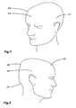
- Figures 1 and 2 illustrate a head of a wearer.
- the head comprises a crown region CR, left and right side regions LS, RS, a back region BR and an occipital region OC.
- the crown region CR has a front part that substantially corresponds to the forehead and a top part that substantially corresponds to the front top part of the head. In fact, the crown region CR generally corresponds to the frontal bone region of the head.
- the left and right side regions LS, RS are approximately located above the ears of the wearer.
- Occipital region OC substantially corresponds to the region around and under the external occipital protuberance of the head.
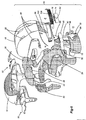
- the hockey helmet 10 comprises a front portion 12 and a rear portion 14 interconnected together.
- Front and rear portions 12, 14 comprise respective front shell 16 and rear shell 18, the rear shell comprising inner and outer surfaces 96, 98.
- the front shell 16 and rear shell 18 may be made of a relatively rigid material, such as NYLON, polycarbonate materials, thermoplastics, or thermosetting resins or any other suitable material.
- the front and rear shells 16, 18 includes a plurality of ventilation apertures 20 that provide the added comfort of allowing air to circulate around the head of the wearer.
- the front shell 16 overlays front inner pad 22 and top inner pad 30 while the rear shell overlays rear central inner pad 24 and left and right side inner pads 26, 28.
- the front inner pad 22 faces the front part of the crown region CR while the top inner pad 30 faces the top part of the crown region CR.
- the central rear inner pad 24 faces the back region BR while the left and right side inner pads 26, 28 face the left and right side regions LS, RS.
- the inner pads 22, 24, 26, 28 may be made of shock absorbing materials such as expanded polypropylene (EPP) or expanded polyethylene (EPE). Other materials can also be used without departing from the spirit of the invention.
- the front inner pad 22 and top inner pad 30 have three-dimensional configurations that match the three-dimensional configurations of the front shell 16 and are attached to the inner surfaces of the front shell 16 by any suitable means such glue, stitches, tacks, staples or rivets.
- rear central inner pad 24 and left and right side inner pads 26, 28 have three-dimensional configurations that match the three-dimensional configurations of the rear shells 18 and are attached to the inner surface 96 of the rear shells 18 by any suitable means, such as glue, stitches, tacks, staples or rivets.
- the helmet 10 may also comprise a front comfort liner 32 affixed on the inner surface of the front inner pad 22, a top comfort liner 38 affixed on the inner surface of the top inner pad 30 and left and right side comfort liners 34, 36 affixed on the inner surface of the respective left and right side inner pads 26, 28.
- the comfort liners 32, 34, 36 and 38 may be made of soft materials such as polyvinyl chloride (PVC). Other materials can also be used without departing from the spirit of the invention.
- PVC polyvinyl chloride
- the comfort liners 32, 34, 36 and 38 may be affixed on the inner surface of the respective inner pads 22, 26, 28 and 30 by any suitable means, such as glue, stitches, tacks, staples or rivets.
- the hockey helmet 10 may comprise left and right ear loops and a chin strap adapted to be attached to ear loops so that when it is secured beneath the chin of the wearer, the helmet 10 is maintained onto the head of the wearer. If desired, the helmet 10 may be provided with left and right ear covers for protecting the ears of the wearer.
- the front and rear portions 12, 14 can move one with relation to the other so as to adjust the size of the head receiving cavity of the helmet 10.
- Left and right locking mechanisms 50, 52 retain the front and rear portions 12, 14 in the position selected by the wearer. Any suitable type of locking mechanisms such as the one described in U.S. Patent 5,956,776 of Bauer Nike Hockey Inc. issued on September 28, 1999 can be used without departing from the spirit of the invention.
- the wearer must simply release the locking mechanism 50, 52 expand or contract the size of the helmet 10 by displacing the front and the rear portion 12, 14 in relation to each other in the appropriate direction.
- helmet 10 may comprise a non-adjustable one-piece shell covering a one-piece inner pad and a one-piece comfort liner.
- the helmet 10 may comprise separate front and rear portions 12, 14 that are connected to one another in any suitable way but not adjustable one relative to the other.
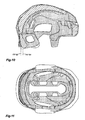
- Figures 7 to 14 show an occipital adjustment mechanism comprising an occipital inner pad 54 facing the occipital region OC of the head, the occipital inner pad 54 being movable between a first position FP 54 (see Figures 10-11 ) to a second position SP 54 (see Figures 12-13 ).
- the occipital inner pad 54 applies pressure upon the occipital region OC for urging the front portion 12 (front shell 16, front and top inner pads 22, 30 and front and top comfort liners 32, 38) towards the crown region CR (as previously indicated, the crown region CR has a front part that substantially corresponds to the forehead and a top part that substantially corresponds to the front top part of the head).
- the pressure applied by the occipital inner pad 54 induces a corresponding movement of the helmet 10 towards the back of the head, necessary to seat the front portion 12 of the helmet 10 against the crown region CR of the head.
- the occipital inner pad 54 may apply a first pressure upon the occipital region OC of the head, and in the second position SP 54 , the occipital inner pad 54 applies a second pressure upon the occipital region OC of the head, the second pressure being greater than the first pressure.
- the occipital inner pad 54 may be made of expanded polypropylene (EPP) or expanded polyethylene (EPE). Other materials can also be used without departing from the spirit of the invention.
- the occipital inner pad 54 has an inner surface 56 and may comprise left and right occipital comfort liners 58, 60 positioned symmetrically about the longitudinal axis of the helmet 10 on the inner surface 56 (see Figure 5 ).
- the occipital left and right comfort liners 58, 60 may be made of polyvinyl chloride (PVC) but other materials can also be used without departing from the spirit of the invention.
- the left and right occipital comfort liners 58, 60 may be affixed on the inner surface 56 of the occipital inner pad 54 by any suitable means, such as glue, stitches, tacks, staples or rivets.
- the occipital inner pad 54 may comprise a one-piece occipital comfort liner on the inner surface 56.
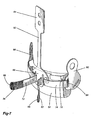
- the occipital adjustment mechanism also comprises an actuator capable of moving the occipital inner pad 54 between the first and second positions FP 54 , SP 54 . More particularly, this actuator comprises a central member 62 and left and right straps 72, 74.
- the left and right straps 72, 74 comprise respective first ends 76, 78 and second ends 80, 82.
- the second ends 80, 82 comprise respective VELCRO ® hooks sections 84, 86.
- the central member 62 extends along the longitudinal axis of the helmet from an upper part 64, that is hingely connected to an inner surface of the rear portion 14 (e.g. to inner surface 96 of rear shell 18), to a lower part 66 that is attached to the occipital inner pad 54.
- the lower part 66 and the upper part 64 may be riveted to the occipital inner pad 54 and the rear shell 18 respectively.
- Other affixing means e.g. glue, stitches, tacks, staples
- the central member 62 may be a sheet-like member as illustrated in Figure 7 .
- the central member 62 is located between the rear shell 18 and the rear central and occipital inner pads 24, 54.
- the lower part 66 is movable from a first position FP 66 (see Figures 10-11 ) to a second position SP 66 (see Figures 12-13 ) wherein, in the second position SP 66 , the occipital inner pad 54 applies pressure upon the occipital region OR for urging the front portion 12 (front shell 16, front and top inner pads 22, 30 and front and top comfort liners 32, 38) towards the crown region CR.
- the lower part 66 comprises left and right passages 68, 70 positioned symmetrically about the longitudinal axis of the helmet 10 (see Figure 6 ).
- the helmet 10 also comprises left and right sheet-like elements 88, 90 affixed to the inner surface 96 of the rear shell 18.
- the left and right sheet-like elements 88, 90 comprise respective passages 92, 94 for receiving the first ends 76, 78 of respective left and right straps 72, 74.
- Each of the first ends 76, 78 may be passed through the respective passages 92, 94, be folded onto a portion of the strap and then be stitched to this portion (see first end 78 in Figure 7 ). In that way, the first ends 76, 78 are retained in the helmet 10.
- the first ends 76, 78 may be directly stitched to the sheet-like elements 88, 90, which then would not comprise passages 92, 94.
- the rear shell 18 comprises left and right openings 100, 102 positioned symmetrically about the longitudinal axis of the helmet 10 for receiving the respective left and right straps 72, 74.
- the outer surface 98 of the rear shell 18 comprises a strip 104 affixed thereon between the left and right openings 100, 102, the strip 104 comprising a VELCRO ® loops section 106.
- the strip 104 may comprise a VELCRO ® hooks section while the second ends 80, 82 may comprise respective VELCRO ® loops sections.
- the strip 104 may be affixed to the outer surface 98 by any suitable means, such as glue, stitches, tacks, staples or rivets.
- the second ends 80, 82 of the straps 72, 74 pass through the respective left and right passages 98, 70 of the lower part 66 and the respective left and right openings 100, 102 of the rear shell 18.
- the second ends 80, 82 of the straps 72, 24 are therefore accessible to the wearer and the lower part 66 of the central member 62 can be moved from the first position FP 66 to the second position SP 66 when the wearer pulls the second ends 80, 82.
- the length of overlap between the left and right straps 72, 74 and the strip 104 controls the degree of pressure applied by the occipital inner pad 54; the more the wearer pulls on the left and right straps 72, 74, the more pressure is applied by the occipital inner pad 54.
- the wearer can put the helmet 10 when the occipital inner pad 54 and lower part 66 are in the respective first positions FP 54 , FP 66 (see Figures 10-11 ).
- the wearer When the wearer obtains the adequate fitting, he/she then folds the second ends 80, 82 on the strip 104 in order to affix left and right straps 72, 74 to the strip 104 (see Figure 14 ). In that way, the occipital inner pad 54 remains in the selected position wherein the occipital inner pad 54 applies the appropriate pressure. If the amount of pressure is too high, the wearer can simply detach the left and right straps 72, 74 from the strip 104, reduce the length of overlap between the left and right straps 72, 74 and the strip 104, and then fold again the second ends 80, 82 on the strip 104 in order to affix left and right straps 72, 74 to the strip 104.
Description
- The present invention relates to a hockey helmet having an occipital adjustment mechanism for improving the fit of the helmet on the head of the wearer.
- German Utility Model GM
77 29 063 issued on December 29, 1977 relates to a protective helmet. The helmet comprises a shell, an insulating layer, a soft lining and inflatable air cushions located between the insulating layer and lining, these air cushions being connected with each other by air tubes. The helmet also comprises a bellows, a check valve and an actuation element. -
U.S. Patent No. 5,815,847 entitled One size fits all baseball batter's helmet issued on October 6, 1998. This patent relates to a batter's protective helmet having a relatively rigid helmet and a padding within the helmet. The padding includes crown, front, opposite side and rear protective pad portions. A strap is provided for adjusting the overall size of the padding. The strap has end portions which project through openings in the rear portion of the helmet with each end portion having fasteners for fastening to a fastener provided on the helmet between the openings. -
U.S. Patent No. 5,898,950 entitled Protective Helmet issued to Spyrou et al. on May 4, 1999. This patent relates to a helmet comprising a protective shell and releasable attachment means having a first front strap, a second front strap, attachment members, a rear strap, a first side strap, a second side strap, a rear plate, a first support strap and a second support strap. The rear strap comprises an outer region, a first lower extension and a second lower extension, the lower extensions providing a means for cradling the head of the wearer. -
Canadian Patent Application 2,414,872 relates to a hockey helmet having an inflatable bladder for improving the fit of the helmet on the head of the wearer. The inflatable bladder is located adjacent the occipital region of the head and may be inflated by a pump. - Against this background, there is a need in the industry for a helmet that provides a better fitting on the head of the wearer.
- As embodied and broadly described herein, the present invention provides a hockey helmet as defined in claim 1.
- A detailed description of the embodiments of the present invention is provided herein below, by way of example only, with reference to the accompanying drawings, in which:
-
Figure 1 is a perspective view of a head of a wearer; -
Figure 2 is a right side elevational view of the head of the wearer ofFigure 1 ; -
Figure 3 is a perspective view of a hockey helmet constructed in accordance with an embodiment of the invention; -
Figure 4 is a right side elevational view of the hockey helmet ofFigure 3 ; -
Figure 5 is a front exploded perspective view of the hockey helmet ofFigure 3 ; -
Figure 6 a rear exploded perspective view of the hockey helmet ofFigure 3 ; -
Figure 7 is a perspective view of an occipital adjustment mechanism for the hockey helmet ofFigure 3 ; -
Figure 8 is a right side elevational view of the hockey helmet ofFigure 3 wherein a portion of the outer shell is cut-away; -
Figure 9 is a rear elevational view of the hockey helmet ofFigure 3 wherein a portion of the outer shell is cut-away; -
Figure 10 is a cross-sectional view taken along lines 10-10; -
Figure 11 is a bottom view of the hockey helmet ofFigure 3 with the occipital inner pad shown in a first position; and -
Figure 12 is a bottom view of the hockey helmet with the occipital inner pad shown in a second position; -
Figure 13 is a cross-sectional view with the occipital inner pad shown in the second position; and -
Figure 14 is an enlarged partial bottom view of the hockey helmet with the occipital inner pad shown in the second position. - In the drawings, embodiments of the invention are illustrated by way of examples. It is to be expressly understood that the description and drawings are only for the purpose of illustration and are an aid for understanding. They are not intended to be a definition of the limits of the invention.
- To facilitate the description, any reference numeral designating an element in one figure will designate the same element if used in any other figures. In describing the embodiments, specific terminology is resorted to for the sake of clarity but the invention is not intended to be limited to the specific terms so selected, and it is understood that each specific term comprises all equivalents.
-
Figures 1 and 2 illustrate a head of a wearer. The head comprises a crown region CR, left and right side regions LS, RS, a back region BR and an occipital region OC. The crown region CR has a front part that substantially corresponds to the forehead and a top part that substantially corresponds to the front top part of the head. In fact, the crown region CR generally corresponds to the frontal bone region of the head. The left and right side regions LS, RS are approximately located above the ears of the wearer. Occipital region OC substantially corresponds to the region around and under the external occipital protuberance of the head. - Referring to
Figures 3 to 6 , thehockey helmet 10 comprises afront portion 12 and arear portion 14 interconnected together. Front andrear portions respective front shell 16 andrear shell 18, the rear shell comprising inner andouter surfaces front shell 16 andrear shell 18 may be made of a relatively rigid material, such as NYLON, polycarbonate materials, thermoplastics, or thermosetting resins or any other suitable material. The front andrear shells ventilation apertures 20 that provide the added comfort of allowing air to circulate around the head of the wearer. - The
front shell 16 overlays frontinner pad 22 and topinner pad 30 while the rear shell overlays rear centralinner pad 24 and left and right sideinner pads inner pad 22 faces the front part of the crown region CR while the topinner pad 30 faces the top part of the crown region CR. The central rearinner pad 24 faces the back region BR while the left and right sideinner pads inner pads - The front
inner pad 22 and topinner pad 30 have three-dimensional configurations that match the three-dimensional configurations of thefront shell 16 and are attached to the inner surfaces of thefront shell 16 by any suitable means such glue, stitches, tacks, staples or rivets. Similarly, rear centralinner pad 24 and left and right sideinner pads rear shells 18 and are attached to theinner surface 96 of therear shells 18 by any suitable means, such as glue, stitches, tacks, staples or rivets. - The
helmet 10 may also comprise afront comfort liner 32 affixed on the inner surface of the frontinner pad 22, atop comfort liner 38 affixed on the inner surface of the topinner pad 30 and left and rightside comfort liners inner pads comfort liners comfort liners inner pads - The
hockey helmet 10 may comprise left and right ear loops and a chin strap adapted to be attached to ear loops so that when it is secured beneath the chin of the wearer, thehelmet 10 is maintained onto the head of the wearer. If desired, thehelmet 10 may be provided with left and right ear covers for protecting the ears of the wearer. - The front and
rear portions 12, 14 (front andrear shells helmet 10. Left and right lockingmechanisms rear portions U.S. Patent 5,956,776 of Bauer Nike Hockey Inc. issued on September 28, 1999 can be used without departing from the spirit of the invention. - In operation, a wearer who puts on the
helmet 10 and realizes that it is too large or too small, does not need to remove thehelmet 10 to adjust it. The wearer must simply release thelocking mechanism helmet 10 by displacing the front and therear portion - Alternatively,
helmet 10 may comprise a non-adjustable one-piece shell covering a one-piece inner pad and a one-piece comfort liner. In another possible variant, thehelmet 10 may comprise separate front andrear portions -
Figures 7 to 14 show an occipital adjustment mechanism comprising an occipitalinner pad 54 facing the occipital region OC of the head, the occipitalinner pad 54 being movable between a first position FP54 (seeFigures 10-11 ) to a second position SP54 (seeFigures 12-13 ). In the second position SP54, the occipitalinner pad 54 applies pressure upon the occipital region OC for urging the front portion 12 (front shell 16, front and topinner pads top comfort liners 32, 38) towards the crown region CR (as previously indicated, the crown region CR has a front part that substantially corresponds to the forehead and a top part that substantially corresponds to the front top part of the head). Depending on how tightly the head of the wearer fits in the head receiving cavity of thehelmet 10, the pressure applied by the occipitalinner pad 54 induces a corresponding movement of thehelmet 10 towards the back of the head, necessary to seat thefront portion 12 of thehelmet 10 against the crown region CR of the head. Also, depending on how tightly the head of the wearer fits in the head receiving cavity of the helmet, in the first position FP54, the occipitalinner pad 54 may apply a first pressure upon the occipital region OC of the head, and in the second position SP54, the occipitalinner pad 54 applies a second pressure upon the occipital region OC of the head, the second pressure being greater than the first pressure. - The occipital
inner pad 54 may be made of expanded polypropylene (EPP) or expanded polyethylene (EPE). Other materials can also be used without departing from the spirit of the invention. The occipitalinner pad 54 has aninner surface 56 and may comprise left and rightoccipital comfort liners helmet 10 on the inner surface 56 (seeFigure 5 ). The occipital left andright comfort liners occipital comfort liners inner surface 56 of the occipitalinner pad 54 by any suitable means, such as glue, stitches, tacks, staples or rivets. Alternatively, the occipitalinner pad 54 may comprise a one-piece occipital comfort liner on theinner surface 56. - The occipital adjustment mechanism also comprises an actuator capable of moving the occipital
inner pad 54 between the first and second positions FP54, SP54. More particularly, this actuator comprises acentral member 62 and left andright straps right straps sections - The
central member 62 extends along the longitudinal axis of the helmet from anupper part 64, that is hingely connected to an inner surface of the rear portion 14 (e.g. toinner surface 96 of rear shell 18), to alower part 66 that is attached to the occipitalinner pad 54. Thelower part 66 and theupper part 64 may be riveted to the occipitalinner pad 54 and therear shell 18 respectively. Other affixing means (e.g. glue, stitches, tacks, staples) can be used without departing from the spirit of the invention. Thecentral member 62 may be a sheet-like member as illustrated inFigure 7 . Thecentral member 62 is located between therear shell 18 and the rear central and occipitalinner pads - The
lower part 66 is movable from a first position FP66 (seeFigures 10-11 ) to a second position SP66 (seeFigures 12-13 ) wherein, in the second position SP66, the occipitalinner pad 54 applies pressure upon the occipital region OR for urging the front portion 12 (front shell 16, front and topinner pads top comfort liners 32, 38) towards the crown region CR. Thelower part 66 comprises left andright passages Figure 6 ). - The
helmet 10 also comprises left and right sheet-like elements inner surface 96 of therear shell 18. The left and right sheet-like elements respective passages right straps respective passages first end 78 inFigure 7 ). In that way, the first ends 76, 78 are retained in thehelmet 10. Alternatively, the first ends 76, 78 may be directly stitched to the sheet-like elements passages - The
rear shell 18 comprises left andright openings helmet 10 for receiving the respective left andright straps Figures 5 and6 , theouter surface 98 of therear shell 18 comprises astrip 104 affixed thereon between the left andright openings strip 104 comprising a VELCRO® loops section 106. It is understood that thestrip 104 may comprise a VELCRO® hooks section while the second ends 80, 82 may comprise respective VELCRO® loops sections. Thestrip 104 may be affixed to theouter surface 98 by any suitable means, such as glue, stitches, tacks, staples or rivets. - The second ends 80, 82 of the
straps right passages lower part 66 and the respective left andright openings rear shell 18. The second ends 80, 82 of thestraps lower part 66 of thecentral member 62 can be moved from the first position FP66 to the second position SP66 when the wearer pulls the second ends 80, 82. Respective portions of the left andright straps strip 104 such that these portions are affixable to thestrip 104 between first and second positions, wherein, in the second position, the occipitalinner pad 54 applies pressure upon the occipital region OR for urging thefront shell 16 towards the crown region CR. - The length of overlap between the left and
right straps strip 104 controls the degree of pressure applied by the occipitalinner pad 54; the more the wearer pulls on the left andright straps inner pad 54. For example, the wearer can put thehelmet 10 when the occipitalinner pad 54 andlower part 66 are in the respective first positions FP54, FP66 (seeFigures 10-11 ). If the wearer realizes that the fitting is not adequate, he/she then detaches overlapping portions of left andright straps strip 104 and, as illustrated inFigures 12-13 , pulls second ends 80, 82 in order to move the occipitalinner pad 54 andlower part 66 to the respective second positions SP54, SP66 (note that the wearer does not necessarily remove the helmet during this adjustment). As indicated previously, pressure applied by the occipitalinner pad 54 upon the occipital region OR urges the front portion of the helmet towards the crown region CR. Moreover, the pressure applied upon the occipital region OC of the head is greater in the second position SP54 than the one applied in the first position FP54. - When the wearer obtains the adequate fitting, he/she then folds the second ends 80, 82 on the
strip 104 in order to affix left andright straps Figure 14 ). In that way, the occipitalinner pad 54 remains in the selected position wherein the occipitalinner pad 54 applies the appropriate pressure. If the amount of pressure is too high, the wearer can simply detach the left andright straps strip 104, reduce the length of overlap between the left andright straps strip 104, and then fold again the second ends 80, 82 on thestrip 104 in order to affix left andright straps strip 104. - The above description of the embodiments should not be interpreted in a limiting manner since other variations, modifications and refinements are possible within the scope of the invention as defined in the appended claims.
Claims (21)
- A hockey helmet (10) for receiving a head of a wearer, the head having a crown region (CR), left and right side regions (LS, RS), a back region (BR) and an occipital region (OC), said helmet comprising: (a) a front portion (12) for facing the crown region of the head; (b) a rear portion (14) for facing the left and right side regions (LS, RS), the back region (BR) and the occipital region of the head (OC); and (c) an occipital inner pad (54) located between said rear portion (14) of said helmet and the occipital region of the head, said helmet being characterized in that it comprises an actuator comprising a central member (62) extending along a longitudinal axis of said helmet from an upper part (64) that is hingedly connected to an inner surface of said rear portion of said helmet to a lower part (66) that is attached to said occipital inner pad (54), said lower part of said central member being movable from a first position to a second position wherein, in said second position, said occipital inner pad applies pressure upon the occipital region of the head for urging said front portion (12) of said helmet towards the crown region of the head.
- A hockey helmet as defined in claim 1, comprising left and right sheet-like elements (88, 90) affixed to said inner surface of said rear portion of said helmet, and wherein said lower part (66) of said central member (62) comprises left and right passages (68, 70) positioned symmetrically about the longitudinal axis of said helmet and wherein said actuator comprises left and right straps (72, 74) for passing through said left and right passages of said lower part respectively.
- A hockey helmet as defined in claim 2, wherein each left and right sheet-like element (88, 90) comprises a passage (92, 94), each of said left and right straps (72, 74) comprises first and second ends (76, 78; 80, 82), each first end (76, 78) being received in each passage of said left and right elements, each second end (80, 82) being adapted to be accessible to the wearer such that said lower part (66) of said central member (62) is movable from said first position to said second position when the wearer pulls each second end of said left end right straps.
- A hockey helmet as defined in claim 3, wherein each second end (80, 82) of said left and right straps (72, 74) comprises a VELCRO® hooks section or a VELCRO® loops section.
- A hockey helmet as defined in claim 4, wherein said front portion (12) and said rear portion (14) comprise respective front and rear shells (16, 18), said front shell comprising an inner surface and said rear shell comprising outer and inner surfaces (96, 98), said inner surface (96) of said rear shell corresponding to said inner surface of said rear portion.
- A hockey helmet as defined in claim 5, wherein said rear shell (18) comprises left and right openings (100, 102) positioned symmetrically about the longitudinal axis of said helmet for receiving respective left and right straps (72, 74) such that each second end (80, 82) of said left and right straps is adapted to be accessible to the wearer.
- A hockey helmet as defined in claim 6, wherein said outer surface (98) of said rear shell (18) comprises a strip (104) affixed thereon between said left and right openings (100, 102) of said rear shell, said strip comprising a VELCRO® loops section or a VELCRO® hooks section.
- A hockey helmet as defined in claim 7, wherein each second end of said left and right straps (72, 74) overlaps said strip (104) such that each end is affixable to said strip between first and second positions, wherein, in said second position, said occipital inner pad applies pressure upon the occipital region of the head for urging said front portion towards the crown region of the head.
- A hockey helmet as defined in any one of claims 5 to 8, wherein said upper part (64) of said central member (62) is affixed to said inner surface (96) of said rear shell.
- A hockey helmet as defined in any one of claims 1 to 9, wherein said lower part (66) of said central member is riveted to said occipital inner pad (54).
- A hockey helmet as defined in any one of claims 5 to 10, wherein said left and right sheet-like elements (88, 90) are affixed to said inner surface (96) of said rear shell.
- A hockey helmet as defined in any one of claims 1 to 11, wherein said occipital inner pad (54) is made of expanded polypropylene (EPP) or expanded polyethylene (EPE).
- A hockey helmet as defined in any one of claims 1 to 12, wherein said occipital inner pad (54) comprises an occipital comfort liner (58; 60) affixed to an inner surface of said occipital inner pad.
- A hockey helmet as defined in claim 13, wherein said occipital comfort liner comprises left and right occipital comfort liners (58, 60) positioned symmetrically about the longitudinal axis of said helmet.
- A hockey helmet as defined in claim 14, wherein said left and right occipital comfort liners (58, 60) are made of polyvinyl chloride (PVC).
- A hockey helmet as defined in any one of claims 5 to 15, comprising a front inner pad (22) and a top inner pad (30) affixed on said inner surface of said front shell.
- A hockey helmet as defined in any one of claims 5 to 16, comprising a rear central inner pad (24) and left and right side inner pads (26, 28) affixed on said inner surface of said rear shell.
- A hockey helmet as defined in claim 16, comprising a front comfort liner (32) affixed on an inner surface of said front inner pad (22) and a top comfort liner (38) affixed on an inner surface of said top inner pad (30).
- A hockey helmet as defined in claim 17, comprising left and right side comfort liners (34, 36) affixed on an inner surface of respective said left and right inner pads (26, 28).
- A hockey helmet as defined in any one of claims 5 to 19, wherein said front shell (16) is movable relative to said rear shell (18) for allowing size adjustment of said helmet.
- A hockey helmet as defined in claim 1 or 2, wherein said actuator comprises a strap (72; 74) having a first end (76, 78) in said helmet and a second end (80, 82) adapted to be accessible to the wearer, said strap cooperating with said central member (62) such that said occipital inner pad (54) moves to said second position when the wearer pulls said second end of said strap.
Applications Claiming Priority (2)
| Application Number | Priority Date | Filing Date | Title |
|---|---|---|---|
| CA002437626A CA2437626C (en) | 2003-08-15 | 2003-08-15 | Hockey helmet comprising an occipital adjustment mechanism |
| CA2437626 | 2003-08-15 |
Publications (2)
| Publication Number | Publication Date |
|---|---|
| EP1510143A1 EP1510143A1 (en) | 2005-03-02 |
| EP1510143B1 true EP1510143B1 (en) | 2008-04-02 |
Family
ID=34085289
Family Applications (1)
| Application Number | Title | Priority Date | Filing Date |
|---|---|---|---|
| EP03292840A Expired - Lifetime EP1510143B1 (en) | 2003-08-15 | 2003-11-14 | Hockey helmet comprising an occipital adjustement mechanism |
Country Status (5)
| Country | Link |
|---|---|
| US (1) | US6968575B2 (en) |
| EP (1) | EP1510143B1 (en) |
| CA (1) | CA2437626C (en) |
| DE (1) | DE60320103D1 (en) |
| RU (1) | RU2350236C2 (en) |
Families Citing this family (53)
| Publication number | Priority date | Publication date | Assignee | Title |
|---|---|---|---|---|
| CA2573639C (en) * | 2004-07-14 | 2012-05-15 | Sport Maska Inc. | Adjustable helmet |
| DE602005025888D1 (en) * | 2004-07-14 | 2011-02-24 | Sport Maska Inc | ADJUSTABLE HELMET |
| WO2007013106A1 (en) * | 2005-07-27 | 2007-02-01 | Safilo Società Azionaria Fabbrica | A protective helmet, particularly for sports use |
| WO2007019653A1 (en) * | 2005-08-18 | 2007-02-22 | Mauricio Paranhos Torres | Cephalic protection cell (cpc) |
| US7870618B2 (en) | 2005-09-30 | 2011-01-18 | Sport Maska Inc. | Adjustment mechanism for a helmet |
| US7827617B2 (en) * | 2005-10-21 | 2010-11-09 | Bae Systems Specialty Defense Systems Of Pennsylvania, Inc. | Chin strap assembly for helmet |
| US7941873B2 (en) * | 2005-11-23 | 2011-05-17 | Scott W. Nagely | Protective helmet with cervical spine protection and additional brain protection |
| US7430767B2 (en) * | 2005-11-23 | 2008-10-07 | Nagely Scott W | Protective helmet with motion restrictor |
| FR2894784B1 (en) * | 2005-12-15 | 2008-07-18 | Pjdo Soc Par Actions Simplifie | FOLDING PROTECTIVE HELMET |
| US7908678B2 (en) * | 2005-12-22 | 2011-03-22 | Brine Iii William H | Sport helmet with adjustable liner |
| US7634820B2 (en) * | 2006-01-20 | 2009-12-22 | Sport Maska Inc. | Adjustment mechanism for a helmet |
| US8056150B2 (en) * | 2007-05-08 | 2011-11-15 | Warrior Sports, Inc. | Helmet adjustment system |
| US8156574B2 (en) | 2007-05-08 | 2012-04-17 | Warrior Sports, Inc. | Helmet adjustment system |
| US8296868B2 (en) | 2007-08-17 | 2012-10-30 | Easton Sports, Inc. | Adjustable hockey helmet |
| US8191179B2 (en) * | 2008-01-25 | 2012-06-05 | Bauer Hockey, Inc. | Hockey helmet with an outer shell made of two different materials |
| CA2659638C (en) * | 2008-03-21 | 2013-07-23 | Mission Itech Hockey Ltd. | Helmet for a hockey or lacrosse player |
| US7954178B2 (en) * | 2008-08-27 | 2011-06-07 | Bauer Hockey, Inc. | Hockey helmet comprising an occipital adjustment mechanism |
| US8510870B2 (en) * | 2009-08-26 | 2013-08-20 | Warrior Sports, Inc. | Adjustable helmet and related method of use |
| USD679865S1 (en) | 2010-05-17 | 2013-04-09 | Louis Garneau Sports Inc. | Helmet |
| DE102010026998A1 (en) * | 2010-07-13 | 2012-01-19 | Anton Pfanner | Clamping unit for a carrying strap of a protective helmet, in particular for forestry workers |
| US9226539B2 (en) | 2010-07-13 | 2016-01-05 | Sport Maska Inc. | Helmet with rigid shell and adjustable liner |
| EP2425730B1 (en) | 2010-09-03 | 2014-03-12 | Bauer Hockey Corp. | Helmet comprising an occipital adjustment mechanism |
| US8739318B2 (en) | 2010-09-03 | 2014-06-03 | Bauer Hockey, Inc. | Helmet comprising an occipital adjustment mechanism |
| US20120079646A1 (en) * | 2010-10-05 | 2012-04-05 | Guillaume Belanger | Hockey helmet with readily removable earpieces |
| US8850624B2 (en) | 2011-05-23 | 2014-10-07 | Honeywell International, Inc. | Headgear with a spring buffered occipital cradle |
| US9032558B2 (en) | 2011-05-23 | 2015-05-19 | Lionhead Helmet Intellectual Properties, Lp | Helmet system |
| US9345282B2 (en) * | 2011-07-27 | 2016-05-24 | Bauer Hockey, Inc. | Adjustable helmet for a hockey or lacrosse player |
| EP2550882B1 (en) | 2011-07-27 | 2019-08-21 | Bauer Hockey Ltd. | Sport helmet |
| EP2742817A3 (en) | 2011-07-27 | 2014-09-17 | Bauer Hockey Corp. | Sports helmet with rotational impact protection |
| CA2783078C (en) * | 2011-07-28 | 2015-11-10 | Bauer Hockey Corp. | Ear protector for a hockey or lacrosse helmet |
| USD669226S1 (en) | 2011-11-22 | 2012-10-16 | Warrior Sports, Inc. | Helmet |
| US9179729B2 (en) * | 2012-03-13 | 2015-11-10 | Boa Technology, Inc. | Tightening systems |
| US20130289459A1 (en) * | 2012-04-25 | 2013-10-31 | Gene P. Bernardoni | Cranial helmet for infants |
| FR2994061B1 (en) * | 2012-08-01 | 2015-03-27 | Salomon Sas | PROTECTIVE HELMET FOR SPORTS ACTIVITY |
| US9307802B2 (en) | 2012-10-22 | 2016-04-12 | Revision Military S.A.R.L. | Helmet suspension system |
| US9403080B2 (en) * | 2013-09-30 | 2016-08-02 | Bauer Hockey, Inc. | Sport helmet comprising an occipital inner pad mounted to a movable rear support |
| WO2015089646A1 (en) | 2013-12-19 | 2015-06-25 | Bauer Hockey Corp. | Helmet for impact protection |
| US10238165B2 (en) | 2014-03-07 | 2019-03-26 | Bell Sports, Inc. | Enduro mountain biking chin bar |
| EP3273818A4 (en) * | 2015-03-24 | 2019-01-02 | Gentex Corporation | Helmet retention system |
| US9961952B2 (en) | 2015-08-17 | 2018-05-08 | Bauer Hockey, Llc | Helmet for impact protection |
| US10709193B2 (en) * | 2016-02-03 | 2020-07-14 | Zzm Enterprises, Llc | Goalie helmet |
| EP3429383A4 (en) * | 2016-03-16 | 2019-11-13 | Falcon Helmet Design&engineering, Inc. | Form-fitting protective headgear with integrated fastening system and detachable eye shield |
| JP1598541S (en) | 2017-03-16 | 2018-02-26 | ||
| CA3187910A1 (en) * | 2017-11-21 | 2019-05-31 | Bauer Hockey Ltd. | Helmet |
| CN111669984B (en) | 2017-12-01 | 2023-09-29 | 泽图有限公司 | Head-mounted assembly and electrode for sensing biopotential and method of operating the same |
| US11524188B2 (en) | 2018-10-09 | 2022-12-13 | Checkmate Lifting & Safety Ltd | Tensioning device |
| US20220338592A1 (en) * | 2019-07-03 | 2022-10-27 | Sport Maska Inc. | Adjustable sport helmet |
| US11700903B2 (en) * | 2019-10-07 | 2023-07-18 | Dick's Sporting Goods, Inc. | Adjustable helmet |
| US10869520B1 (en) | 2019-11-07 | 2020-12-22 | Lionhead Helmet Intellectual Properties, Lp | Helmet |
| WO2021188222A2 (en) | 2020-02-06 | 2021-09-23 | Galvion Ltd. | Rugged integrated helmet vision system |
| US11832677B2 (en) | 2021-05-12 | 2023-12-05 | Galvion Incorporated | System for forming a deep drawn helmet |
| US11547166B1 (en) | 2022-02-11 | 2023-01-10 | Lionhead Helmet Intellectual Properties, Lp | Helmet |
| US11641904B1 (en) | 2022-11-09 | 2023-05-09 | Lionhead Helmet Intellectual Properties, Lp | Helmet |
Family Cites Families (26)
| Publication number | Priority date | Publication date | Assignee | Title |
|---|---|---|---|---|
| US3028602A (en) * | 1960-12-19 | 1962-04-10 | Mine Safety Appliances Co | Helmet head positioner |
| US3991423A (en) * | 1975-09-08 | 1976-11-16 | General Aquadyne, Inc. | Helmet with actuated neck pad |
| DE7729063U1 (en) | 1977-09-20 | 1977-12-29 | Schuberth-Werk, 3300 Braunschweig | Hard hat |
| SE450620B (en) * | 1982-11-01 | 1987-07-13 | Frosta Fritid Ab | PROTECTIVE HELMET WITH SIZE ADJUSTMENT, SPEC FOR ISHOCKEY AND BANDY PLAYERS |
| US4713844A (en) * | 1986-07-16 | 1987-12-22 | Gentex Corporation | Protective helmet with face mask sealing means |
| FR2638070B1 (en) * | 1988-10-21 | 1991-07-12 | Parinter Sa | ADJUSTABLE HAIRDRESSER AND HAIRDRESSER EQUIPPED WITH THIS HAIRDRESSER |
| US5315718A (en) * | 1992-04-30 | 1994-05-31 | The United States Of America As Represented By The Secretary Of The Army | Protective helmet and retention system therefor |
| US5381560A (en) * | 1993-03-23 | 1995-01-17 | Pdh Corporation | Fitting and retention system for headgear |
| US5659900A (en) * | 1993-07-08 | 1997-08-26 | Bell Sports, Inc. | Sizing and stabilizing apparatus for bicycle helmets |
| FR2719748B1 (en) * | 1994-05-10 | 1996-08-23 | Overforing | Device for occipital fixation of a helmet. |
| US5511250A (en) * | 1995-01-26 | 1996-04-30 | A-Star Sports Group, Inc. | Adjustable protective helmet |
| US5584073A (en) * | 1995-04-12 | 1996-12-17 | Gentex Corporation | Integrated helmet system |
| US5581819A (en) * | 1995-10-18 | 1996-12-10 | Garneau; Louis | Protective headgear and abutment plate thereof |
| ATE213394T1 (en) * | 1996-11-29 | 2002-03-15 | Bauer Nike Hockey Inc | HOCKEY HELMET WITH SELF-ADJUSTABLE PADDING |
| US5915537A (en) * | 1997-01-09 | 1999-06-29 | Red Corp. | Helmet |
| CN1117535C (en) * | 1997-05-14 | 2003-08-13 | 海茵茨·埃格尔福 | Helmet with adjustable safety strap |
| US5815847A (en) * | 1997-06-23 | 1998-10-06 | Ampac Enterprises, Inc. | One size fits all baseball batter's helmet |
| JP3019946B2 (en) | 1997-10-16 | 2000-03-15 | 株式会社ホンダアクセス | Helmet |
| US5898950A (en) * | 1997-11-26 | 1999-05-04 | Sport Maska Inc. | Protective helmet |
| WO1999029199A1 (en) * | 1997-12-12 | 1999-06-17 | Soccer Strategies, L.L.C. | Impact protection headguard |
| US5953761A (en) * | 1998-01-26 | 1999-09-21 | Ampac Enterprises, Inc. | Protective headgear |
| US6108824A (en) * | 1998-08-12 | 2000-08-29 | Sport Maska Inc. | Helmet adjustment mechanism with quick release |
| US6226802B1 (en) * | 2000-03-15 | 2001-05-08 | Specialized Bicycle Components, Inc. | Retention mechanism for a helmet |
| CA2365894A1 (en) | 2001-12-21 | 2003-06-21 | Bauer Nike Hockey Inc. | Sporting helmet having an inflatable bladder with a pump |
| AU2003247414A1 (en) * | 2002-05-14 | 2003-12-02 | White Water Research And Safety Institute, Inc. | Protective headgear for whitewater use |
| US6865752B2 (en) * | 2002-12-23 | 2005-03-15 | Wilson Sporting Goods Co. | Adjustable sports helmet |
-
2003
- 2003-08-15 CA CA002437626A patent/CA2437626C/en not_active Expired - Lifetime
- 2003-11-13 US US10/705,838 patent/US6968575B2/en not_active Expired - Lifetime
- 2003-11-14 DE DE60320103T patent/DE60320103D1/en not_active Expired - Lifetime
- 2003-11-14 EP EP03292840A patent/EP1510143B1/en not_active Expired - Lifetime
-
2004
- 2004-08-13 RU RU2004124691/12A patent/RU2350236C2/en not_active IP Right Cessation
Also Published As
| Publication number | Publication date |
|---|---|
| US20050034222A1 (en) | 2005-02-17 |
| US6968575B2 (en) | 2005-11-29 |
| RU2004124691A (en) | 2006-02-10 |
| DE60320103D1 (en) | 2008-05-15 |
| CA2437626C (en) | 2009-04-14 |
| RU2350236C2 (en) | 2009-03-27 |
| CA2437626A1 (en) | 2005-02-15 |
| EP1510143A1 (en) | 2005-03-02 |
Similar Documents
| Publication | Publication Date | Title |
|---|---|---|
| EP1510143B1 (en) | Hockey helmet comprising an occipital adjustement mechanism | |
| US11026465B2 (en) | Helmet comprising an occipital adjustment mechanism | |
| US20030135914A1 (en) | Hockey helmet comprising an inflatable bladder | |
| EP1506722B1 (en) | Hockey helmet comprising a lateral adjustment mechanism | |
| US3447162A (en) | Safety helmet with improved stabilizing and size adjusting means | |
| US7954178B2 (en) | Hockey helmet comprising an occipital adjustment mechanism | |
| US5014365A (en) | Gas-fitted protective helmet | |
| US5515546A (en) | Foldable padded helmet | |
| US8142377B2 (en) | Double pull body brace | |
| CA1059253A (en) | Protective helmet | |
| US7673350B2 (en) | Universal safety cap | |
| EP0497032A1 (en) | Helmet | |
| US4024586A (en) | Headgear suspension system | |
| US20020166157A1 (en) | Fitting and comfort system with inflatable liner for helmet | |
| JP2007522352A (en) | Semi-rigid protective helmet | |
| WO2005096857A2 (en) | Protective helmet assembly having lightweight suspension system | |
| US20020083512A1 (en) | Wrestling ear guard | |
| CA2714314C (en) | Helmet comprising an occipital adjustment mechanism | |
| EP2425730B1 (en) | Helmet comprising an occipital adjustment mechanism | |
| EP1411791B1 (en) | Head protection apparatus | |
| CA2414872A1 (en) | Hockey helmet comprising an inflatable bladder | |
| CA2639192C (en) | Hockey helmet comprising an occipital adjustment mechanism |
Legal Events
| Date | Code | Title | Description |
|---|---|---|---|
| PUAI | Public reference made under article 153(3) epc to a published international application that has entered the european phase |
Free format text: ORIGINAL CODE: 0009012 |
|
| AK | Designated contracting states |
Kind code of ref document: A1 Designated state(s): AT BE BG CH CY CZ DE DK EE ES FI FR GB GR HU IE IT LI LU MC NL PT RO SE SI SK TR |
|
| AX | Request for extension of the european patent |
Extension state: AL LT LV MK |
|
| 17P | Request for examination filed |
Effective date: 20050712 |
|
| AKX | Designation fees paid |
Designated state(s): CH CZ DE FI FR LI SE |
|
| 17Q | First examination report despatched |
Effective date: 20061218 |
|
| GRAP | Despatch of communication of intention to grant a patent |
Free format text: ORIGINAL CODE: EPIDOSNIGR1 |
|
| GRAS | Grant fee paid |
Free format text: ORIGINAL CODE: EPIDOSNIGR3 |
|
| GRAA | (expected) grant |
Free format text: ORIGINAL CODE: 0009210 |
|
| AK | Designated contracting states |
Kind code of ref document: B1 Designated state(s): CH CZ DE FI FR LI SE |
|
| RAP2 | Party data changed (patent owner data changed or rights of a patent transferred) |
Owner name: NIKE BAUER HOCKEY INC. |
|
| REG | Reference to a national code |
Ref country code: CH Ref legal event code: EP |
|
| REF | Corresponds to: |
Ref document number: 60320103 Country of ref document: DE Date of ref document: 20080515 Kind code of ref document: P |
|
| RAP2 | Party data changed (patent owner data changed or rights of a patent transferred) |
Owner name: NIKE BAUER HOCKEY CORP. |
|
| RAP2 | Party data changed (patent owner data changed or rights of a patent transferred) |
Owner name: NIKE INTERNATIONAL LTD. |
|
| REG | Reference to a national code |
Ref country code: SE Ref legal event code: TRGR |
|
| RAP2 | Party data changed (patent owner data changed or rights of a patent transferred) |
Owner name: NIKE BAUER HOCKEY INC. |
|
| RAP2 | Party data changed (patent owner data changed or rights of a patent transferred) |
Owner name: NIKE BAUER HOCKEY CORP. |
|
| RAP2 | Party data changed (patent owner data changed or rights of a patent transferred) |
Owner name: NIKE BAUER HOCKEY LTD. |
|
| RAP2 | Party data changed (patent owner data changed or rights of a patent transferred) |
Owner name: NIKE BAUER HOCKEY CORP. |
|
| PG25 | Lapsed in a contracting state [announced via postgrant information from national office to epo] |
Ref country code: FI Free format text: LAPSE BECAUSE OF FAILURE TO SUBMIT A TRANSLATION OF THE DESCRIPTION OR TO PAY THE FEE WITHIN THE PRESCRIBED TIME-LIMIT Effective date: 20080402 |
|
| EN | Fr: translation not filed | ||
| PLBE | No opposition filed within time limit |
Free format text: ORIGINAL CODE: 0009261 |
|
| STAA | Information on the status of an ep patent application or granted ep patent |
Free format text: STATUS: NO OPPOSITION FILED WITHIN TIME LIMIT |
|
| 26N | No opposition filed |
Effective date: 20090106 |
|
| PG25 | Lapsed in a contracting state [announced via postgrant information from national office to epo] |
Ref country code: DE Free format text: LAPSE BECAUSE OF FAILURE TO SUBMIT A TRANSLATION OF THE DESCRIPTION OR TO PAY THE FEE WITHIN THE PRESCRIBED TIME-LIMIT Effective date: 20080703 |
|
| REG | Reference to a national code |
Ref country code: CH Ref legal event code: PL |
|
| PG25 | Lapsed in a contracting state [announced via postgrant information from national office to epo] |
Ref country code: LI Free format text: LAPSE BECAUSE OF NON-PAYMENT OF DUE FEES Effective date: 20081130 Ref country code: CH Free format text: LAPSE BECAUSE OF NON-PAYMENT OF DUE FEES Effective date: 20081130 |
|
| PG25 | Lapsed in a contracting state [announced via postgrant information from national office to epo] |
Ref country code: FR Free format text: LAPSE BECAUSE OF FAILURE TO SUBMIT A TRANSLATION OF THE DESCRIPTION OR TO PAY THE FEE WITHIN THE PRESCRIBED TIME-LIMIT Effective date: 20090123 |
|
| PGFP | Annual fee paid to national office [announced via postgrant information from national office to epo] |
Ref country code: CZ Payment date: 20151104 Year of fee payment: 13 |
|
| PG25 | Lapsed in a contracting state [announced via postgrant information from national office to epo] |
Ref country code: CZ Free format text: LAPSE BECAUSE OF NON-PAYMENT OF DUE FEES Effective date: 20161114 |
|
| PGFP | Annual fee paid to national office [announced via postgrant information from national office to epo] |
Ref country code: SE Payment date: 20201110 Year of fee payment: 18 |
|
| PG25 | Lapsed in a contracting state [announced via postgrant information from national office to epo] |
Ref country code: SE Free format text: LAPSE BECAUSE OF NON-PAYMENT OF DUE FEES Effective date: 20211115 |