EP1509640B1 - Design einer zelle zur elektrolytischen gewinnung von aluminium mit beweglichen ioslierabdeckungsteilen - Google Patents
Design einer zelle zur elektrolytischen gewinnung von aluminium mit beweglichen ioslierabdeckungsteilen Download PDFInfo
- Publication number
- EP1509640B1 EP1509640B1 EP03756086A EP03756086A EP1509640B1 EP 1509640 B1 EP1509640 B1 EP 1509640B1 EP 03756086 A EP03756086 A EP 03756086A EP 03756086 A EP03756086 A EP 03756086A EP 1509640 B1 EP1509640 B1 EP 1509640B1
- Authority
- EP
- European Patent Office
- Prior art keywords
- cell
- electrolyte
- movable
- section
- anode
- Prior art date
- Legal status (The legal status is an assumption and is not a legal conclusion. Google has not performed a legal analysis and makes no representation as to the accuracy of the status listed.)
- Expired - Lifetime
Links
- 239000004411 aluminium Substances 0.000 title claims abstract description 54
- 229910052782 aluminium Inorganic materials 0.000 title claims abstract description 54
- XAGFODPZIPBFFR-UHFFFAOYSA-N aluminium Chemical compound [Al] XAGFODPZIPBFFR-UHFFFAOYSA-N 0.000 title claims abstract description 54
- 238000005363 electrowinning Methods 0.000 title claims abstract description 10
- 239000003792 electrolyte Substances 0.000 claims abstract description 85
- OKTJSMMVPCPJKN-UHFFFAOYSA-N Carbon Chemical compound [C] OKTJSMMVPCPJKN-UHFFFAOYSA-N 0.000 claims abstract description 15
- 229910052799 carbon Inorganic materials 0.000 claims abstract description 15
- 150000001399 aluminium compounds Chemical class 0.000 claims abstract description 14
- 238000005868 electrolysis reaction Methods 0.000 claims abstract description 9
- PNEYBMLMFCGWSK-UHFFFAOYSA-N aluminium oxide Inorganic materials [O-2].[O-2].[O-2].[Al+3].[Al+3] PNEYBMLMFCGWSK-UHFFFAOYSA-N 0.000 claims description 17
- 238000010079 rubber tapping Methods 0.000 claims description 15
- 238000000034 method Methods 0.000 claims description 11
- KRHYYFGTRYWZRS-UHFFFAOYSA-M Fluoride anion Chemical compound [F-] KRHYYFGTRYWZRS-UHFFFAOYSA-M 0.000 claims description 5
- 230000015572 biosynthetic process Effects 0.000 claims description 2
- 230000000284 resting effect Effects 0.000 claims 1
- 210000004027 cell Anatomy 0.000 description 71
- 238000004519 manufacturing process Methods 0.000 description 10
- 239000010410 layer Substances 0.000 description 4
- 239000000919 ceramic Substances 0.000 description 3
- 239000007789 gas Substances 0.000 description 3
- 210000003168 insulating cell Anatomy 0.000 description 3
- 239000000463 material Substances 0.000 description 3
- XEEYBQQBJWHFJM-UHFFFAOYSA-N Iron Chemical compound [Fe] XEEYBQQBJWHFJM-UHFFFAOYSA-N 0.000 description 2
- PXHVJJICTQNCMI-UHFFFAOYSA-N Nickel Chemical compound [Ni] PXHVJJICTQNCMI-UHFFFAOYSA-N 0.000 description 2
- 239000011195 cermet Substances 0.000 description 2
- 238000001816 cooling Methods 0.000 description 2
- 238000009413 insulation Methods 0.000 description 2
- 239000000725 suspension Substances 0.000 description 2
- 229910000831 Steel Inorganic materials 0.000 description 1
- XVVDIUTUQBXOGG-UHFFFAOYSA-N [Ce].FOF Chemical compound [Ce].FOF XVVDIUTUQBXOGG-UHFFFAOYSA-N 0.000 description 1
- 238000009825 accumulation Methods 0.000 description 1
- 239000000956 alloy Substances 0.000 description 1
- 229910045601 alloy Inorganic materials 0.000 description 1
- 239000010405 anode material Substances 0.000 description 1
- QVGXLLKOCUKJST-UHFFFAOYSA-N atomic oxygen Chemical compound [O] QVGXLLKOCUKJST-UHFFFAOYSA-N 0.000 description 1
- JLQUFIHWVLZVTJ-UHFFFAOYSA-N carbosulfan Chemical compound CCCCN(CCCC)SN(C)C(=O)OC1=CC=CC2=C1OC(C)(C)C2 JLQUFIHWVLZVTJ-UHFFFAOYSA-N 0.000 description 1
- 150000001785 cerium compounds Chemical class 0.000 description 1
- 239000011248 coating agent Substances 0.000 description 1
- 238000000576 coating method Methods 0.000 description 1
- 239000002131 composite material Substances 0.000 description 1
- 229910001610 cryolite Inorganic materials 0.000 description 1
- 238000005265 energy consumption Methods 0.000 description 1
- 238000005516 engineering process Methods 0.000 description 1
- 230000017525 heat dissipation Effects 0.000 description 1
- 238000010438 heat treatment Methods 0.000 description 1
- 239000011810 insulating material Substances 0.000 description 1
- 230000002452 interceptive effect Effects 0.000 description 1
- 229910052742 iron Inorganic materials 0.000 description 1
- 229910052751 metal Inorganic materials 0.000 description 1
- 239000002184 metal Substances 0.000 description 1
- 239000007769 metal material Substances 0.000 description 1
- 229910052759 nickel Inorganic materials 0.000 description 1
- 238000013021 overheating Methods 0.000 description 1
- 229910052760 oxygen Inorganic materials 0.000 description 1
- 239000001301 oxygen Substances 0.000 description 1
- 239000011241 protective layer Substances 0.000 description 1
- 150000003839 salts Chemical class 0.000 description 1
- 239000007787 solid Substances 0.000 description 1
- 239000007921 spray Substances 0.000 description 1
- 239000010959 steel Substances 0.000 description 1
- 238000006467 substitution reaction Methods 0.000 description 1
Images
Classifications
-
- C—CHEMISTRY; METALLURGY
- C25—ELECTROLYTIC OR ELECTROPHORETIC PROCESSES; APPARATUS THEREFOR
- C25C—PROCESSES FOR THE ELECTROLYTIC PRODUCTION, RECOVERY OR REFINING OF METALS; APPARATUS THEREFOR
- C25C3/00—Electrolytic production, recovery or refining of metals by electrolysis of melts
- C25C3/06—Electrolytic production, recovery or refining of metals by electrolysis of melts of aluminium
- C25C3/08—Cell construction, e.g. bottoms, walls, cathodes
Definitions
- the invention relates to an aluminium electrowinning cell having non-carbon anodes in a molten electrolyte that is covered with a thermic insulating cover comprising movable cover sections and to the production of aluminium with such a cell.
- This crust/ledge of solidified electrolyte forms part of the cell's heat dissipation system in view of the need to keep the cell in operation at constant temperature despite changes in operating conditions, as when anodes are replaced, or due to damage/wear to the sidewalls, or due to over-heating or cooling as a result of great fluctuations in the operating conditions.
- the crust is used as a means for automatically maintaining a satisfactory thermal balance, because the crust/ledge thickness self-adjusts to compensate for thermic unbalances. If the cell overheats, the crust dissolves partly thereby reducing the thermic insulation, so that more heat is dissipated through the sidewalls leading to cooling of the cell contents. On the other hand, if the cell cools, the crust thickens which increases the thermic insulation, so that less heat is dissipated, leading to heating of the cell contents.
- the presence of a crust of solidified electrolyte is considered to be important to achieve satisfactory operation of commercial cells for the production of aluminium on a large scale.
- the heat balance is one of the major concerns of cell design and energy consumption, since only about 25% of such energy is used for the production of aluminium.
- Optimisation of the heat balance is needed to keep the proper bath temperature and heat flow to maintain a frozen electrolyte layer (side ledge) with a proper thickness.
- US Patent 5,368,702 discloses a multimonopolar aluminium production cell operating with tubular anodes in a crustless molten electrolyte which is thermally insulated by a cover. The cover is lined underneath with a layer of thermally insulating material.
- US Patent 5,415,742 (La Camera/Tomaswick/Ray/Ziegler) discloses another aluminium production cell operating with a crustless molten electrolyte which is thermally insulated by a cover.
- WO02/06565 (D'Astolfo/Hornack ), US publications 2001/0035344 (D'Astolfo/Lazzaro ) and 2001/0037946 (D'Astolfo/Moor ) disclose an aluminium production cell having thermally insulating cover sections over the cell's electrolyte and several inert anode blocks that are suspended from each cover section, the cover sections serving also to distribute current to the inert anode blocks connected thereto.
- US Patent 6,402,928 discloses an aluminium production cell having an insulating cover made of sections associated with individual anodes or groups of anodes, the insulating cover being removable by sections so that the individual anodes or groups of anodes can be separately replaced or serviced by removing only the removable sections associated therewith.
- the invention relates to a cell for the electrowinning of aluminium from an aluminium compound dissolved in a molten electrolyte, in particular by the electrolysis of alumina dissolved in a fluoride-based molten electrolyte.
- the cell comprises: (I) a plurality of individual non-carbon anodes or a plurality of groups of non-carbon anodes, each individual anode or group of anodes being suspended in operation in the molten electrolyte by an anode stem that connects the individual anode or the group of anodes to a positive current source; and (II) a thermic insulating cover which covers the electrolyte and through which each anode stem extends from the positive current source to an individual anode or a group of anodes.
- the insulating cover comprises a plurality of movable sections that, together, cover a substantial part of the electrolyte.
- Each movable section covers a corresponding portion of the electrolyte that is located therebelow and that can be uncovered by moving the corresponding movable section.
- the anode stem of each individual anode or group of anodes extends through the insulating cover between two movable sections or between a movable section and a fixed section of the insulating cover when said sections are side-by-side in a covering position over the electrolyte.
- Each movable section is movable to uncover the corresponding electrolyte portion without interrupting operation of any individual anode or group of anodes.
- the movable cover section of the present invention can be moved away from its covering position over the molten electrolyte without having to interrupt operation of any anode, i.e. while maintaining supply into the electrolyte of an electrolysis current from each anode (or each group of anodes) to electrolyse the aluminium compound dissolved in the electrolyte. In particular it is not necessary to disconnect the anodes or move the anodes out of an operating location while covering or uncovering portions of the molten electrolyte.
- the entire electrolyte surface or at least a significant portion thereof can be accessed during use without significantly interfering with the electrolysis process.
- a significant portion usually corresponds to more than a third, typically at least half, preferably no less than two thirds and even more preferably at least three quarter of the electrolyte surface.
- the insulating cell cover can be made of any material, e.g. ceramic, resistant to high temperature oxidising/corrosive environment, in particular to an oxygen and fluoride containing atmosphere.
- the cover is made of a composite material disclosed in WO02/070784 (de Nora/Berclaz ).
- each movable section is individually movable to uncover only the corresponding electrolyte portion so as to minimise heat loss as far as possible.
- Each individual anode or group of anodes can be associated with at least one movable cover section, usually one, two, three or four movable sections, and is replaceable or serviceable by moving only the movable section(s) associated therewith.
- At least one movable cover section can be associated with a plurality of individual anodes or groups of anodes.
- one movable cover section is associated with a plurality of anodes that are located adjacent one edge and/or adjacent neighbouring edges and/or opposite edges of the movable cover section.
- each individual anode or each group of anodes extends under the insulating cover sidewards from a bottom end of the anode stem by which it is suspended.
- Examples of such anodes are disclosed in US Patents 6,358,393 (Berclaz/de Nora ) and 6,540,887 (de Nora ), and in WO99/02764 (de Nora/Duruz ), WO00/40781, (de Nora ), WO01/31086 (de Nora/Duruz ), WO03/006716 and WO03/023092 (both de Nora ).
- the anodes can be horizontally confined under the anode stems, for example as disclosed in US Patent 5,368,702 (de Nora ) and WO01/31088 (de Nora ).
- the anode can be an oxygen-evolving ceramic, cermet or metal-based anode.
- the anode can be made of any of the materials disclosed in WO00/06802 , WO00/06803 (both in the name of Duruz/de Nora/Crottaz ), WO00/06804 (Crottaz/Duruz ), WO01/42535 (Duruz/de Nora ), WO01/42534 (de Nora/Duruz ), WO01/42536 (Duruz/Nguyen/de Nora ), WO02/083991 (Nguyen/de Nora ), WO03/014420 (Nguyen/Duruz/de Nora ) and PCT/IB03/00964 (Nguyen/de Nora).
- Oxygen-evolving anodes may be coated with a protective layer made of one or more cerium compounds, in particular cerium oxyfluoride, as disclosed in WO02/070786 (Nguyen/de Nora ), WO02/0083990 (de Nora/Nguyen ), and in US Patents 4,614,569 (Duruz/Derivaz/Debely/Adorian ), 4,680,094 (Duruz ), 4,683,037 (Duruz ) and 4,966,674 (Bannochie/Sheriff ).
- cerium compounds in particular cerium oxyfluoride
- the insulating cover may comprise a plurality of movable cover sections placed side-by-side, in particular side-by-side along the cell.
- An anode stem can extend through the cell cover between two side-by-side movable cover sections.
- the insulating cover may comprise a plurality of movable cover sections placed end-to-end, in particular end-to-end across the cell.
- An anode stem can extend through the cell cover between two end-to-end movable cover sections.
- the insulating cover may comprise a fixed cover section and a movable cover section adjacent thereto over the electrolyte.
- the insulating cover comprises a central fixed cover section extending along the cell and one or more movable cover sections on each side of the central cover section and over the electrolyte.
- An anode stem can extend through the cell cover between the fixed cover section and the movable cover section.
- a movable cover section can be pivotally mounted along a horizontal axis in particular adjacent to and generally along an upper part of a cell sidewall, so that the movable section can be pivoted from and back into its covering position.
- the section can be associated with a counterweight located beyond the pivoting axis opposite the section.
- a movable cover section can also be separable from the cell during operation.
- a movable cover section can rest on a cell sidewall and/or on a fixed cover section or may be suspended over the electrolyte by suspension means, such as wires or chains.
- suspension means such as wires or chains.
- the suspension means is connected to a drive means, such as an electric motor, or to a counterweight to move or assist movements of the movable section.
- a movable cover section comprises a gripping means, such as a handle or a ring, for moving or assisting movements of the section manually (by hand), in particular using a crowbar, or an attachment means, such as a hook or ring, for moving or assisting movements of the section with a lifting device, such as a crane.
- a gripping means such as a handle or a ring
- an attachment means such as a hook or ring
- the cell of the invention in particular when in a drained configuration, has an arrangement for accumulating product aluminium above which a movable cover section is arranged to be intermittently moved away from its covering position for allowing access of an aluminium tapping device to this arrangement.
- a movable cover section is arranged to be intermittently moved away from its covering position for allowing access of an aluminium tapping device to this arrangement.
- Suitable aluminium accumulation arrangements are disclosed in WO00/63463 , WO02/097169 (de Nora ) or WO02/097168 (all de Nora ).
- This movable cover section can be associated with one or more anodes or can be a separate movable cover section.
- the insulating cover comprises at least one opening for feeding an aluminium compound to the molten electrolyte.
- alumina feeders can be conventional point feeders or feeders that are arranged to spray/spread alumina over the molten electrolyte, for example as disclosed in WO00/63464 (de Nora/Berclaz ) and WO03/006717 (Berclaz/Duruz ). If the alumina feeder is not permanently in the aluminium feeding opening, this opening can be fitted with a movable closure member for reducing heat loss while the feeder is not in the opening.
- the invention also relates to a method of electrowinning aluminium in a cell as described above.
- the method comprises electrolysing an aluminium compound between the individual anodes or the groups of anodes and a cathode to produce gas anodically and produce aluminium cathodically, maximising the covering of the electrolyte to maintain the electrolyte substantially thermally insulated and inhibit formation of an electrolyte crust on at least part of the electrolyte, and feeding an aluminium compound to this part of the electrolyte for replenishing the aluminium compound consumed during electrolysis.
- the covering of the electrolyte is maximised by moving away from its/their covering position only the movable cover section(s) (vertically) above a portion of the electrolyte that needs to be accessed and only for the time required for the access.
- Aluminium can be accumulated below a movable cover section and intermittently extracted from the cell by: moving the movable cover section that covers the accumulated aluminium away from its covering position; introducing from outside the cell a tapping device into the accumulated aluminium; tapping the accumulated aluminium; extracting the tapping device from the cell; and moving the movable cover section back into its covering position.
- a movable cover section can be mounted in different ways. During cell operating the movable section can be tilted, in particular pivoted, slided and/or lifted to move it away from its covering position.
- An aluminium compound in particular alumina, can be fed to the electrolyte through at least one opening in the insulating cover.
- the cell can be operated with a deep pool of aluminium.
- the cell is operated with a shallow layer of aluminium or in a drained configuration.
- the cathode, and possibly other parts of the cell are covered with an aluminium-wettable material, for example as disclosed in WO01/42168 (de Nora/Duruz ), WO01/42531 (Nguyen/Duruz/de Nora ), WO02/070783 , WO02/070785 (both de Nora ), WO02/09683 (Duruz/Nguyen/de Nora ), WO02/09683 (Nguyen/de Nora ), WO02/097168 and WO02/097169 (both de Nora ).
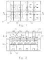
- Figures 1 and 2 illustrate an aluminium electrowinning cell having a series of anodes 10 (shown in dotted lines on the left-hand side of Figure 1) connected to a positive current source and suspended over a cathode bottom 20 by anode stems 11.
- the cathode bottom 20 is made of side-by-side carbon blocks covered with an aluminium-wettable coating 21 and product aluminium 55 and connected to a negative bus bar through steel bars 25 that extend along the cathode blocks.
- the cathode can be covered with a shallow pool of molten aluminium (not shown) or with a thin layer of aluminium 55 as shown in Fig. 2, the cathode bottom 20 being in a drained configuration in which case the cell bottom should be provided with an aluminium collection reservoir, for instance as disclosed in the abovementioned references.
- the anodes 10 are immersed in a molten fluoride-based electrolyte 50 covered by an insulating cover that is made of movable sections 60 arranged side-by-side along the cell and in pairs end-to-end across the cell.
- the anode rods 11 extend through the insulating cover between side-by-side sections 60 which have cut-outs 63 that fit around the anode stems 11.
- Vertical passages 64 for feeding alumina are formed by facing cut-outs between pairs of movable sections 60 across the cell.
- the movable cover sections 60 rest on cell sidewalls 22 whose inner faces 22' are shown in dotted lines on the left-hand side of Fig.1.
- the cover sections 60 are suspended over the electrolyte 50 by wires 70 which are attached at one end to fasteners 71 on the sections 60 and which lead to electric motors 72 or other drive means secured on horizontal support beams 73 that extend longitudinally over the cell.
- wires 70 extends from adjacent one edge of cover section 60 to a motor 72 placed substantially vertically above that edge
- each wire 70 extends from adjacent one edge of cover section 60 to a motor 72 located substantially vertically above an opposite edge of cover section 60 so that the wires 70 are in an X configuration facilitating the tilting of the cover section 60 by using motor 72.
- the movable cover sections 60 are fitted with handles 61 for manually moving them or, if they are moved using motors 72, for manually assisting guiding of the sections during motion.
- the anodes 10 have an active structure, e.g. a grid-like or plate-like structure as disclosed in the abovementioned references, that extends sideways under the movable cover sections 60.
- the anodes could be tubular without extending sideways under the movable cover sections as mentioned above.
- the non-carbon anodes 10 as well as the anode stem 11 can be made of a conductive ceramic, cermet or metal-based material resistant to the molten electrolyte.
- the anodes 10 and the stems 11 are made of an iron-based alloy containing for example nickel as discussed above.
- alumina dissolved in the molten electrolyte 50 is electrolysed between the non-carbon anodes 10 and the cathode bottom 20 to evolve gas anodically and aluminium 55 cathodically.
- Fresh alumina is fed continuously or intermittently through passages 64 to replenish the electrolyte 50.
- Alumina can be fed using conventional point feeders or alumina sprayers as mentioned above.
- An anode 10 can be individually serviced or replaced by moving the two corresponding movable cover sections 60 located thereabove.
- the two movable sections 60 surrounding the anode stem 11 of the anode 10 are tilted generally around their longest edge opposite that receiving anode stem 11, preferably using the electric motors 72 and/or handles 61, and placed against the neighbouring anode stems 11 adjacent the anode 10 that needs to be accessed.
- the corresponding anode 10 can then be extracted from the electrolyte 50.
- one anode 10 of the cell according to the invention can be extracted from the cell and the anode's corresponding cover sections 60 can be put back into their covering positions with a different anode inserted in the cell or, temporarily, even without any anode at all, for example to avoid heat loss while the extracted anode undergoes a quick examination and/or a servicing procedure and is then put back into the cell without anode substitution.
- a movable cover section 60 For tapping accumulated aluminium 55, a movable cover section 60 is moved away from its covering position, a tapping device is introduced from outside the cell into the accumulated aluminium 55, and the accumulated aluminium 55 is tapped. Thereafter, the tapping device is extracted from the cell and the movable cover section 60 is moved back into its covering position.
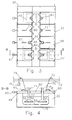
- FIGS 3 and 4 schematically show another cell according to the invention.
- the cell has a series of anodes 10 (shown in dotted lines in the upper part and in the lower part of Figure 3) connected to a positive current source and suspended over a cathode bottom 20 by anode stems 11.
- the anodes 10 are immersed in a molten fluoride-based electrolyte 50 covered by an insulating cover 60,60' made of a central fixed cover section 60' and movable sections 60 placed on each side of fixed section 60' and arranged side-by-side along the cell.
- Each anode stem 11 extends through the insulating cover 60,60' between fixed section 60' and a movable section 60 shown tilted in dotted lines on the right-hand side of Fig.4, it being understood that the movable section 60 can be pivoted to about a vertical position.
- the movable sections 60 have cut-outs 63,63' that fit around the anode stems 11. As shown on the upper part of Fig. 3, the cut-outs 63 extend into movable sections 60 so as to accommodate only the anode stems 11, whereas on the lower part of Fig. 3, the cut-outs 63' extend farther into the movable sections 60 so as to accommodate the anode stems 11 as well as protrusions 65 of fixed section 60'.
- the anode stems 11 have a greater spacing across the cell between them. This permits optimised use of the surface of the cathode bottom 20 and/or use of larger anodes and/or utilisation of a central channel (not shown) for collecting product aluminium 55, as mentioned above.
- the fixed cover sections are fitted with cut-outs that fit around the anode stems (not shown).
- a cut-out can accommodate only an anode stem or an anode stem plus a protrusion of the movable cover sections.
- the movable cover sections 60 are pivotally mounted along a horizontal axis 66 adjacent to and along an upper part of longitudinal cell sidewalls 22, the inner faces 22' of the sidewalls being indicated in dotted lines in the upper part and in the lower part of Fig. 3, and are fitted with handles 61, like the movable cover sections 60 of Figures 1 and 2.
- the movable cover sections 60 are connected to a schematically shown counterweight 67 located beyond the pivoting axis 66 opposite the movable sections 60 for assisting lifting the sections 60.
- the cover sections 60 have protrusions 62 that rest on fixed section 60' and are suspended over the electrolyte 50 by wires 70 through fasteners 71.
- the wires are connected to electric motors 72 or other drive means secured on a horizontal support beams 73 that extend over and across the cell.
- the wires 70 extend over pulleys 74 mounted on beam 73 and are connected to another counterweight 75 for assisting the lifting of movable cover section 60.
- Each movable cover section can be associated with a drive means as well as one or more counterweights.
- alumina dissolved in the molten electrolyte 50 is electrolysed between the non-carbon anodes 10 and the cathode bottom 20 to evolve gas anodically and aluminium 55 cathodically.
- Fresh alumina is fed continuously or intermittently through passages 64 to replenish the electrolyte 50.
- An anode 10 can be individually serviced or replaced by removing the corresponding movable cover section 60 located thereabove.
- the movable section 60 surrounding the anode stem 11 of the anode 10 can be pivoted automatically using motor 72 or manually using handle 61.
- the corresponding anode 10 can then be extracted from the electrolyte 50.
- a movable cover section 60 For tapping accumulated aluminium 55, a movable cover section 60 is moved away from its covering position, a tapping device is introduced from outside the cell into the accumulated aluminium, and the accumulated aluminium is tapped. Thereafter, the tapping device is extracted from the cell and the movable cover section 60 is moved back into its covering position.
- the insulating cell cover in particular a fixed cover section thereof, can be fitted with an additional smaller opening specifically designed for allowing passage of an aluminium tapping device.
- This additional opening is preferably covered with a corresponding movable closure when no aluminium is tapped to avoid heat loss.
Landscapes
- Chemical & Material Sciences (AREA)
- Engineering & Computer Science (AREA)
- Chemical Kinetics & Catalysis (AREA)
- Electrochemistry (AREA)
- Materials Engineering (AREA)
- Metallurgy (AREA)
- Organic Chemistry (AREA)
- Electrolytic Production Of Metals (AREA)
- Secondary Cells (AREA)
Claims (27)
- Zelle zum elektrolytischen Gewinnen von Aluminium aus einer in einem geschmolzenen Elektrolyten gelösten Aluminiumverbindung, insbesondere durch Elektrolyse von in einem auf Fluorid basierenden geschmolzenen Elektrolyten gelöstem Aluminiumoxid, die- eine Vielzahl von einzelnen kohlenstofffreien Anoden oder eine Vielzahl von Gruppen von kohlenstofffreien Anoden, wobei jede einzelne Anode oder Gruppe von Anoden beim Betrieb in dem geschmolzenen Elektrolyten durch einen Anodenstamm aufgehängt ist, der die einzelnen Anode oder die Gruppe von Anoden mit einer positiven Stromquelle verbindet, und- eine thermisch isolierende Abdeckung umfasst, die den Elektrolyten bedeckt und durch die sich jeder Anodenstamm von der positiven Stromquelle zu einer einzelnen Anode oder einer Gruppe von Anoden erstreckt, wobei die isolierende Abdeckung eine Vielzahl von beweglichen Abschnitten umfasst, die zusammen einen wesentlichen Teil des Elektrolyten bedecken,dadurch gekennzeichnet, dass sich der Anodenstamm jeder einzelnen Anode oder Gruppe von Anoden durch die isolierende Abdeckung zwischen zwei beweglichen Abschnitten oder zwischen einem beweglichen Abschnitt und einem festen Abschnitt der isolierenden Abdeckung erstreckt, wenn die Abschnitte in einer bedeckenden Position über dem Elektrolyten vorliegen, wobei jeder bewegliche Abschnitt beweglich ist, um den entsprechenden Elektrolyteil ohne Unterbrechung des Betriebs irgendeiner einzelnen Anode oder irgendeiner Gruppe von Anoden zu unterbrechen.
wobei jeder bewegliche Abschnitt einen entsprechenden Teil des Elektrolyten bedeckt, der darunter angeordnet ist und durch Bewegung des entsprechenden beweglichen Abschnitts freigelegt werden kann, - Zelle nach Anspruch 1, bei der jeder bewegliche Abschnitt individuell beweglich ist, um nur den entsprechenden Elektrolyteil freizulegen.
- Zelle nach Anspruch 1 oder 2, bei der jede einzelne Anode oder Gruppe von Anoden mit mindestens einem beweglichen Abdeckungsabschnitt verbunden ist und durch Bewegung nur des beweglichen Abschnitts (der beweglichen Abschnitte), der (die) damit verbunden ist (sind), ersetzbar ist oder gewartet werden kann, wobei mindestens ein beweglicher Abdekkungsabschnitt gegebenenfalls mit einer Vielzahl von einzelnen Anoden oder Gruppen von Anoden verbunden ist.
- Zelle nach einem der vorhergehenden Ansprüche, bei der jede einzelne Anode oder jede Gruppe von Anoden sich unter der isolierenden Abdeckung seitwärts von einem Bodenende des Anodenstamms erstreckt, durch den sie aufgehängt ist.
- Zelle nach einem der vorhergehenden Ansprüche, bei der die isolierende Abdeckung eine Vielzahl von beweglichen Abdekkungsabschnitten umfasst, die Seite-an-Seite angeordnet sind, insbesondere Seite-an-Seite entlang der Zelle.
- Zelle nach Anspruch 5, bei der sich ein Anodenstamm zwischen zwei Seite-an-Seite angeordneten beweglichen Abdekkungsabschnitten durch die Zellabdeckung erstreckt.
- Zelle nach einem der vorhergehenden Ansprüche, bei der die isolierende Abdeckung eine Vielzahl von beweglichen Abdekkungsabschnitten umfasst, die Ende-an-Ende angeordnet sind, insbesondere Ende-an-Ende quer über die Zelle.
- Zelle nach Anspruch 7, bei der sich ein Anodenstamm zwischen zwei Ende-an-Ende angeordneten beweglichen Abdekkungsabschnitten durch die Zellabdeckung erstreckt.
- Zelle nach einem der vorhergehenden Ansprüche, bei der die isolierende Abdeckung einen festen Abdeckungsabschnitt und einen beweglichen Abdeckungsabschnitt benachbart dazu über dem Elektrolyten umfasst, wobei sich der zentrale, feste Abdeckungsabschnitt gegebenenfalls entlang der Zelle erstreckt und an jeder Seite mit einem beweglichen Abdekkungsabschnitt über dem Elektrolyten verbunden ist.
- Zelle nach Anspruch 9, bei der sich ein Anodenstamm zwischen dem festen Abdeckungsabschnitt und dem beweglichen Abdeckungsabschnitt durch die Zellabdeckung erstreckt.
- Zelle nach einem der vorhergehenden Ansprüche, bei der ein beweglicher Abdeckungsabschnitt während des Betriebs von der Zelle abnehmbar ist.
- Zelle nach einem der vorhergehenden Ansprüche, bei der ein beweglicher Abdeckungsabschnitt so angeordnet ist, dass er geschoben oder angehoben werden kann, um einen Teil des Elektrolyten freizulegen.
- Zelle nach einem der vorhergehenden Ansprüche, bei der ein beweglicher Abdeckungsabschnitt so angeordnet ist, dass er geneigt, insbesondere geschwenkt werden kann, um einen Teil des Elektrolyten freizulegen, wobei der bewegliche Abdekkungsabschnitt gegebenenfalls drehbar entlang einer horizontalen Achse angebracht ist.
- Zelle nach einem der vorhergehenden Ansprüche, bei der ein beweglicher Abdeckungsabschnitt auf einer Zellseitenwand aufliegt.
- Zelle nach einem der vorhergehenden Ansprüche, die einen festen Abdeckungsabschnitt und einen beweglichen Abdekkungsabschnitt, der darauf aufliegt, umfasst.
- Zelle nach einem der vorhergehenden Ansprüche, die Mittel zur Aufhängung eines beweglichen Abdeckungsabschnitts über dem Elektrolyten umfasst, wobei die Aufhängungsmittel gegebenenfalls mit Antriebsmitteln verbunden sind, um den beweglichen Abdeckungsabschnitt zu bewegen oder Bewegungen des beweglichen Abdeckungsabschnitts zu unterstützen.
- Zelle nach einem der vorhergehenden Ansprüche, bei der ein beweglicher Abdeckungsabschnitt Greifmittel zur Bewegung oder Unterstützung von Bewegungen des Abschnitts auf manuelle Weise umfasst.
- Zelle nach einem der vorhergehenden Ansprüche, bei der ein beweglicher Abdeckungsabschnitt Befestigungsmittel zur Bewegung oder Unterstützung von Bewegungen des Abschnitts mit einer daran anbringbaren Hebevorrichtung umfasst.
- Zelle nach einem der vorhergehenden Ansprüche, die eine Anordnung zur Ansammlung von Produktaluminium umfasst, wobei darüber ein beweglicher Abdeckungsabschnitt angeordnet ist, um mit Unterbrechungen von seiner abdeckenden Position wegbewegt zu werden und einen Zugang einer Aluminiumabführvorrichtung zu dieser Anordnung zu erlauben.
- Zelle nach einem der vorhergehenden Ansprüche, bei der die isolierende Abdeckung mindestens eine Öffnung für die Zufuhr einer Aluminiumverbindung zu dem geschmolzenen Elektrolyten umfasst.
- Verfahren zur elektrolytischen Gewinnung von Aluminium in einer Zelle gemäß einem der vorhergehenden Ansprüche, bei dem eine Aluminiumverbindung zwischen den einzelnen Anoden oder den Gruppen von Anoden und eine Kathode elektrolysiert wird, um anodisch Gas und kathodisch Aluminium herzustellen, wobei die Abdeckung des Elektrolyten maximiert wird, um den Elektrolyten im Wesentlichen thermisch isoliert zu halten und eine Bildung einer Elektrolytkruste auf mindestens einem Teil des Elektrolyten zu hemmen, und eine Aluminiumverbindung zu diesem Teil des Elektrolyten zur Auffrischung der Aluminiumverbindung geführt wird, die während der Elektrolyse verbraucht wurde.
- Verfahren nach Anspruch 21, bei dem zum Ersetzen oder Warten einer einzelnen Anode oder einer Gruppe von Anoden, die durch einen Anodenstamm aufgehängt ist, nur der bewegliche Teil (die beweglichen Teile), der (die) mit den Anodenstamm verbunden ist (sind), bewegt wird (werden).
- Verfahren nach Anspruch 21 oder 22, bei dem ein Teil des Elektrolyten freigelegt wird, indem nur der entsprechende bewegliche Abschnitt bewegt wird.
- Verfahren nach einem der Ansprüche 21 bis 23, bei dem Aluminium unterhalb eines beweglichen Abdeckungsabschnitts gesammelt wird und mit Unterbrechungen gesammeltes Aluminium aus der Zelle entnommen wird, indem:der bewegliche Abdeckungsabschnitt, der das gesammelte Aluminium bedeckt, aus seiner Abdeckungsposition wegbewegt wird,von außerhalb der Zelle eine Abführvorrichtung in das gesammelte Aluminium eingeführt wird,das gesammelte Aluminium abgeführt wird,die Abführvorrichtung aus der Zelle entfernt wird undder bewegliche Abdeckungsabschnitt zurück in seine Abdekkungsposition bewegt wird.
- Verfahren nach einem der Ansprüche 21 bis 24, bei dem ein Teil des Elektrolyten durch Neigen, insbesondere Schwenken, eines beweglichen Abdeckungsabschnitts freigelegt wird.
- Verfahren nach einem der Ansprüche 21 bis 25, bei dem ein Teil des Elektrolyten durch Schieben und/oder Anheben eines beweglichen Abdeckungsabschnitts freigelegt wird.
- Verfahren nach einem der Ansprüche 21 bis 26, bei dem die Aluminiumverbindung durch mindestens eine Öffnung in der isolierenden Abdeckung zu dem Elektrolyten zugeführt wird.
Applications Claiming Priority (3)
| Application Number | Priority Date | Filing Date | Title |
|---|---|---|---|
| WOPCT/IB02/02018 | 2002-06-04 | ||
| IB0202018 | 2002-06-04 | ||
| PCT/IB2003/002360 WO2003102274A1 (en) | 2002-06-04 | 2003-06-03 | Aluminium electrowinning cell design with movable insulating cover sections |
Publications (2)
| Publication Number | Publication Date |
|---|---|
| EP1509640A1 EP1509640A1 (de) | 2005-03-02 |
| EP1509640B1 true EP1509640B1 (de) | 2007-08-29 |
Family
ID=29596066
Family Applications (1)
| Application Number | Title | Priority Date | Filing Date |
|---|---|---|---|
| EP03756086A Expired - Lifetime EP1509640B1 (de) | 2002-06-04 | 2003-06-03 | Design einer zelle zur elektrolytischen gewinnung von aluminium mit beweglichen ioslierabdeckungsteilen |
Country Status (10)
| Country | Link |
|---|---|
| US (1) | US7749363B2 (de) |
| EP (1) | EP1509640B1 (de) |
| AT (1) | ATE371755T1 (de) |
| AU (1) | AU2003232407B2 (de) |
| CA (1) | CA2478546C (de) |
| DE (1) | DE60315974T2 (de) |
| ES (1) | ES2291674T3 (de) |
| NO (1) | NO20050006L (de) |
| NZ (1) | NZ535111A (de) |
| WO (1) | WO2003102274A1 (de) |
Families Citing this family (16)
| Publication number | Priority date | Publication date | Assignee | Title |
|---|---|---|---|---|
| EP1567693B1 (de) * | 2002-12-04 | 2006-03-22 | MOLTECH Invent S.A. | Elektrolysezelle mit verrbesserter zufuhrvorrichtung |
| US8097144B2 (en) * | 2006-03-10 | 2012-01-17 | Rio Tinto Alean International Limited | Aluminium electrowinning cell with enhanced crust |
| JP4671196B2 (ja) * | 2006-10-31 | 2011-04-13 | 株式会社スクウェア・エニックス | ネットワークゲームシステム、ネットワークゲーム用端末装置、ゲーム画面の表示方法、並びにプログラム及び記録媒体 |
| CN101054689B (zh) * | 2007-02-13 | 2010-05-19 | 沈阳铝镁设计研究院 | 铝电解槽的端部保温结构 |
| CN101633324B (zh) * | 2008-07-23 | 2011-06-29 | 沈阳铝镁设计研究院有限公司 | 电解车间集中大修天车滑触线供电方法及结构 |
| US20100155259A1 (en) * | 2008-12-19 | 2010-06-24 | Ramaswamy J | Process for online power cut out of an aluminum reduction cell |
| CA2856778C (en) * | 2014-07-11 | 2021-07-13 | Services Precicad Inc. | Hood panel for aluminum smelter |
| RU2582421C1 (ru) * | 2014-12-29 | 2016-04-27 | Общество с ограниченной ответственностью "Объединенная Компания РУСАЛ Инженерно-технологический центр" | Укрытие электролизера для производства алюминия |
| GB2542555A (en) * | 2015-09-16 | 2017-03-29 | Dubai Aluminium Pjsc | Removable cover and flap for easy access to the intercalary space in a series of electrolytic Hall-Héroult cells |
| GB2542360A (en) * | 2015-09-16 | 2017-03-22 | Dubai Aluminium Pjsc | Hinged grating for easy access to the outer shell of electrolytic cells suitable for the hall-héroult process |
| RU2698162C2 (ru) | 2017-03-01 | 2019-08-22 | Общество с ограниченной ответственностью "Объединенная Компания РУСАЛ Инженерно-технологический центр" | Перфорированный металлический инертный анод для получения алюминия электролизом расплава |
| CN107400901B (zh) * | 2017-09-22 | 2019-03-26 | 张安全 | 一种铝电解槽槽罩 |
| CN110331419B (zh) * | 2019-07-18 | 2021-03-30 | 国家电投集团远达环保工程有限公司重庆科技分公司 | 包含绳索的铝电解槽槽罩系统和铝电解槽装置 |
| CN115012002B (zh) * | 2021-03-05 | 2025-08-22 | 唐国蓉 | 高效环保铝电解槽 |
| US12119509B2 (en) | 2021-06-28 | 2024-10-15 | Rivian Ip Holdings, Llc | Fasteners and assemblies for servicing high voltage components of a battery system |
| US11942658B2 (en) * | 2021-06-28 | 2024-03-26 | Rivian Ip Holdings, Llc | Systems and methods for servicing high voltage components of a battery system |
Family Cites Families (2)
| Publication number | Priority date | Publication date | Assignee | Title |
|---|---|---|---|---|
| US3935090A (en) * | 1974-03-15 | 1976-01-27 | Dmitry Pavlovich Petrusenko | Covering of an aluminum-producing electrolysis cell |
| AU8031298A (en) * | 1997-07-08 | 1999-02-08 | Moltech Invent S.A. | Aluminium production cell design |
-
2003
- 2003-06-03 EP EP03756086A patent/EP1509640B1/de not_active Expired - Lifetime
- 2003-06-03 AT AT03756086T patent/ATE371755T1/de not_active IP Right Cessation
- 2003-06-03 WO PCT/IB2003/002360 patent/WO2003102274A1/en not_active Ceased
- 2003-06-03 CA CA2478546A patent/CA2478546C/en not_active Expired - Fee Related
- 2003-06-03 US US10/506,201 patent/US7749363B2/en not_active Expired - Fee Related
- 2003-06-03 NZ NZ535111A patent/NZ535111A/en unknown
- 2003-06-03 DE DE60315974T patent/DE60315974T2/de not_active Expired - Lifetime
- 2003-06-03 ES ES03756086T patent/ES2291674T3/es not_active Expired - Lifetime
- 2003-06-03 AU AU2003232407A patent/AU2003232407B2/en not_active Ceased
-
2005
- 2005-01-03 NO NO20050006A patent/NO20050006L/no not_active Application Discontinuation
Non-Patent Citations (1)
| Title |
|---|
| None * |
Also Published As
| Publication number | Publication date |
|---|---|
| WO2003102274A1 (en) | 2003-12-11 |
| DE60315974D1 (de) | 2007-10-11 |
| ES2291674T3 (es) | 2008-03-01 |
| NZ535111A (en) | 2006-09-29 |
| ATE371755T1 (de) | 2007-09-15 |
| CA2478546A1 (en) | 2003-12-11 |
| US20050230265A1 (en) | 2005-10-20 |
| EP1509640A1 (de) | 2005-03-02 |
| DE60315974T2 (de) | 2008-05-21 |
| US7749363B2 (en) | 2010-07-06 |
| AU2003232407A1 (en) | 2003-12-19 |
| AU2003232407B2 (en) | 2009-03-05 |
| CA2478546C (en) | 2011-08-02 |
| NO20050006L (no) | 2005-01-03 |
Similar Documents
| Publication | Publication Date | Title |
|---|---|---|
| EP1509640B1 (de) | Design einer zelle zur elektrolytischen gewinnung von aluminium mit beweglichen ioslierabdeckungsteilen | |
| US6656340B2 (en) | Aluminium production cell design | |
| US6692620B2 (en) | Aluminium electrowinning cell with sidewalls resistant to molten electrolyte | |
| US6783656B2 (en) | Low temperature operating cell for the electrowinning of aluminium | |
| US6558526B2 (en) | Method of converting Hall-Heroult cells to inert anode cells for aluminum production | |
| AU2001241757A1 (en) | Method of converting hall-heroult cells to inert anode | |
| EP1423555B1 (de) | Aluminium elektrogewinnungszellen mit geneigten kathoden | |
| CA2295495C (en) | A drained cathode cell for the production of aluminium | |
| EP1392891B1 (de) | Elektrolysezellen zur aluminiumgewinnung mit drainiertem kathodenboden und einem reservoir für aluminium | |
| US6258246B1 (en) | Aluminium electrowinning cell with sidewalls resistant to molten electrolyte | |
| WO2007105124A2 (en) | Aluminium electrowinning cell with reduced heat loss | |
| EP1230436B1 (de) | Aluminium-elektrogewinnungszelle mit gegen den geschmolzenen elektrolyt beständigen seitenwänden | |
| EP1404898A1 (de) | Elektrolysezelle mit einrichtung zur zuführung von pulver |
Legal Events
| Date | Code | Title | Description |
|---|---|---|---|
| PUAI | Public reference made under article 153(3) epc to a published international application that has entered the european phase |
Free format text: ORIGINAL CODE: 0009012 |
|
| 17P | Request for examination filed |
Effective date: 20041028 |
|
| AK | Designated contracting states |
Kind code of ref document: A1 Designated state(s): AT BE BG CH CY CZ DE DK EE ES FI FR GB GR HU IE IT LI LU MC NL PT RO SE SI SK TR |
|
| AX | Request for extension of the european patent |
Extension state: AL LT LV MK |
|
| RIN1 | Information on inventor provided before grant (corrected) |
Inventor name: DE NORA, VITTORIO Inventor name: BERCLAZ, GEORGES |
|
| DAX | Request for extension of the european patent (deleted) | ||
| GRAP | Despatch of communication of intention to grant a patent |
Free format text: ORIGINAL CODE: EPIDOSNIGR1 |
|
| GRAS | Grant fee paid |
Free format text: ORIGINAL CODE: EPIDOSNIGR3 |
|
| GRAA | (expected) grant |
Free format text: ORIGINAL CODE: 0009210 |
|
| AK | Designated contracting states |
Kind code of ref document: B1 Designated state(s): AT BE BG CH CY CZ DE DK EE ES FI FR GB GR HU IE IT LI LU MC NL PT RO SE SI SK TR |
|
| REG | Reference to a national code |
Ref country code: GB Ref legal event code: FG4D |
|
| REG | Reference to a national code |
Ref country code: CH Ref legal event code: EP |
|
| REG | Reference to a national code |
Ref country code: IE Ref legal event code: FG4D |
|
| REF | Corresponds to: |
Ref document number: 60315974 Country of ref document: DE Date of ref document: 20071011 Kind code of ref document: P |
|
| PG25 | Lapsed in a contracting state [announced via postgrant information from national office to epo] |
Ref country code: FI Free format text: LAPSE BECAUSE OF FAILURE TO SUBMIT A TRANSLATION OF THE DESCRIPTION OR TO PAY THE FEE WITHIN THE PRESCRIBED TIME-LIMIT Effective date: 20070829 |
|
| PG25 | Lapsed in a contracting state [announced via postgrant information from national office to epo] |
Ref country code: LI Free format text: LAPSE BECAUSE OF FAILURE TO SUBMIT A TRANSLATION OF THE DESCRIPTION OR TO PAY THE FEE WITHIN THE PRESCRIBED TIME-LIMIT Effective date: 20070829 Ref country code: AT Free format text: LAPSE BECAUSE OF FAILURE TO SUBMIT A TRANSLATION OF THE DESCRIPTION OR TO PAY THE FEE WITHIN THE PRESCRIBED TIME-LIMIT Effective date: 20070829 Ref country code: CH Free format text: LAPSE BECAUSE OF FAILURE TO SUBMIT A TRANSLATION OF THE DESCRIPTION OR TO PAY THE FEE WITHIN THE PRESCRIBED TIME-LIMIT Effective date: 20070829 |
|
| REG | Reference to a national code |
Ref country code: CH Ref legal event code: PL |
|
| REG | Reference to a national code |
Ref country code: ES Ref legal event code: FG2A Ref document number: 2291674 Country of ref document: ES Kind code of ref document: T3 |
|
| PG25 | Lapsed in a contracting state [announced via postgrant information from national office to epo] |
Ref country code: BE Free format text: LAPSE BECAUSE OF FAILURE TO SUBMIT A TRANSLATION OF THE DESCRIPTION OR TO PAY THE FEE WITHIN THE PRESCRIBED TIME-LIMIT Effective date: 20070829 |
|
| ET | Fr: translation filed | ||
| PG25 | Lapsed in a contracting state [announced via postgrant information from national office to epo] |
Ref country code: GR Free format text: LAPSE BECAUSE OF FAILURE TO SUBMIT A TRANSLATION OF THE DESCRIPTION OR TO PAY THE FEE WITHIN THE PRESCRIBED TIME-LIMIT Effective date: 20071130 Ref country code: DK Free format text: LAPSE BECAUSE OF FAILURE TO SUBMIT A TRANSLATION OF THE DESCRIPTION OR TO PAY THE FEE WITHIN THE PRESCRIBED TIME-LIMIT Effective date: 20070829 |
|
| PG25 | Lapsed in a contracting state [announced via postgrant information from national office to epo] |
Ref country code: SK Free format text: LAPSE BECAUSE OF FAILURE TO SUBMIT A TRANSLATION OF THE DESCRIPTION OR TO PAY THE FEE WITHIN THE PRESCRIBED TIME-LIMIT Effective date: 20070829 Ref country code: PT Free format text: LAPSE BECAUSE OF FAILURE TO SUBMIT A TRANSLATION OF THE DESCRIPTION OR TO PAY THE FEE WITHIN THE PRESCRIBED TIME-LIMIT Effective date: 20080129 Ref country code: CZ Free format text: LAPSE BECAUSE OF FAILURE TO SUBMIT A TRANSLATION OF THE DESCRIPTION OR TO PAY THE FEE WITHIN THE PRESCRIBED TIME-LIMIT Effective date: 20070829 |
|
| PG25 | Lapsed in a contracting state [announced via postgrant information from national office to epo] |
Ref country code: SE Free format text: LAPSE BECAUSE OF FAILURE TO SUBMIT A TRANSLATION OF THE DESCRIPTION OR TO PAY THE FEE WITHIN THE PRESCRIBED TIME-LIMIT Effective date: 20071129 Ref country code: RO Free format text: LAPSE BECAUSE OF FAILURE TO SUBMIT A TRANSLATION OF THE DESCRIPTION OR TO PAY THE FEE WITHIN THE PRESCRIBED TIME-LIMIT Effective date: 20070829 |
|
| PLBE | No opposition filed within time limit |
Free format text: ORIGINAL CODE: 0009261 |
|
| STAA | Information on the status of an ep patent application or granted ep patent |
Free format text: STATUS: NO OPPOSITION FILED WITHIN TIME LIMIT |
|
| 26N | No opposition filed |
Effective date: 20080530 |
|
| PG25 | Lapsed in a contracting state [announced via postgrant information from national office to epo] |
Ref country code: MC Free format text: LAPSE BECAUSE OF NON-PAYMENT OF DUE FEES Effective date: 20080630 |
|
| PG25 | Lapsed in a contracting state [announced via postgrant information from national office to epo] |
Ref country code: IE Free format text: LAPSE BECAUSE OF NON-PAYMENT OF DUE FEES Effective date: 20080603 Ref country code: EE Free format text: LAPSE BECAUSE OF FAILURE TO SUBMIT A TRANSLATION OF THE DESCRIPTION OR TO PAY THE FEE WITHIN THE PRESCRIBED TIME-LIMIT Effective date: 20070829 |
|
| PG25 | Lapsed in a contracting state [announced via postgrant information from national office to epo] |
Ref country code: SI Free format text: LAPSE BECAUSE OF FAILURE TO SUBMIT A TRANSLATION OF THE DESCRIPTION OR TO PAY THE FEE WITHIN THE PRESCRIBED TIME-LIMIT Effective date: 20070829 |
|
| PG25 | Lapsed in a contracting state [announced via postgrant information from national office to epo] |
Ref country code: CY Free format text: LAPSE BECAUSE OF FAILURE TO SUBMIT A TRANSLATION OF THE DESCRIPTION OR TO PAY THE FEE WITHIN THE PRESCRIBED TIME-LIMIT Effective date: 20070829 |
|
| PG25 | Lapsed in a contracting state [announced via postgrant information from national office to epo] |
Ref country code: BG Free format text: LAPSE BECAUSE OF FAILURE TO SUBMIT A TRANSLATION OF THE DESCRIPTION OR TO PAY THE FEE WITHIN THE PRESCRIBED TIME-LIMIT Effective date: 20071129 |
|
| PG25 | Lapsed in a contracting state [announced via postgrant information from national office to epo] |
Ref country code: LU Free format text: LAPSE BECAUSE OF NON-PAYMENT OF DUE FEES Effective date: 20080603 Ref country code: HU Free format text: LAPSE BECAUSE OF FAILURE TO SUBMIT A TRANSLATION OF THE DESCRIPTION OR TO PAY THE FEE WITHIN THE PRESCRIBED TIME-LIMIT Effective date: 20080301 |
|
| PG25 | Lapsed in a contracting state [announced via postgrant information from national office to epo] |
Ref country code: TR Free format text: LAPSE BECAUSE OF FAILURE TO SUBMIT A TRANSLATION OF THE DESCRIPTION OR TO PAY THE FEE WITHIN THE PRESCRIBED TIME-LIMIT Effective date: 20070829 |
|
| REG | Reference to a national code |
Ref country code: GB Ref legal event code: 732E Free format text: REGISTERED BETWEEN 20101104 AND 20101110 |
|
| REG | Reference to a national code |
Ref country code: NL Ref legal event code: TD Effective date: 20101125 Ref country code: NL Ref legal event code: SD Effective date: 20101125 |
|
| REG | Reference to a national code |
Ref country code: FR Ref legal event code: TP Ref country code: FR Ref legal event code: CD |
|
| REG | Reference to a national code |
Ref country code: ES Ref legal event code: PC2A Owner name: RIO TINTO ALCAN INTERNATIONAL LIMITED Effective date: 20110504 |
|
| REG | Reference to a national code |
Ref country code: DE Ref legal event code: R081 Ref document number: 60315974 Country of ref document: DE Owner name: RIO TINTO ALCAN INTERNATIONAL LTD., CA Free format text: FORMER OWNER: MOLTECH INVENT S.A., LUXEMBURG/LUXEMBOURG, LU Effective date: 20110816 Ref country code: DE Ref legal event code: R082 Ref document number: 60315974 Country of ref document: DE Representative=s name: BEETZ & PARTNER PATENT- UND RECHTSANWAELTE, DE Effective date: 20110816 |
|
| PGFP | Annual fee paid to national office [announced via postgrant information from national office to epo] |
Ref country code: DE Payment date: 20120627 Year of fee payment: 10 Ref country code: NL Payment date: 20120626 Year of fee payment: 10 |
|
| PGFP | Annual fee paid to national office [announced via postgrant information from national office to epo] |
Ref country code: FR Payment date: 20120705 Year of fee payment: 10 Ref country code: GB Payment date: 20120625 Year of fee payment: 10 |
|
| PGFP | Annual fee paid to national office [announced via postgrant information from national office to epo] |
Ref country code: IT Payment date: 20120621 Year of fee payment: 10 |
|
| PGFP | Annual fee paid to national office [announced via postgrant information from national office to epo] |
Ref country code: ES Payment date: 20120626 Year of fee payment: 10 |
|
| REG | Reference to a national code |
Ref country code: NL Ref legal event code: V1 Effective date: 20140101 |
|
| GBPC | Gb: european patent ceased through non-payment of renewal fee |
Effective date: 20130603 |
|
| REG | Reference to a national code |
Ref country code: DE Ref legal event code: R119 Ref document number: 60315974 Country of ref document: DE Effective date: 20140101 |
|
| REG | Reference to a national code |
Ref country code: FR Ref legal event code: ST Effective date: 20140228 |
|
| PG25 | Lapsed in a contracting state [announced via postgrant information from national office to epo] |
Ref country code: GB Free format text: LAPSE BECAUSE OF NON-PAYMENT OF DUE FEES Effective date: 20130603 Ref country code: DE Free format text: LAPSE BECAUSE OF NON-PAYMENT OF DUE FEES Effective date: 20140101 Ref country code: NL Free format text: LAPSE BECAUSE OF NON-PAYMENT OF DUE FEES Effective date: 20140101 |
|
| PG25 | Lapsed in a contracting state [announced via postgrant information from national office to epo] |
Ref country code: IT Free format text: LAPSE BECAUSE OF NON-PAYMENT OF DUE FEES Effective date: 20130603 Ref country code: FR Free format text: LAPSE BECAUSE OF NON-PAYMENT OF DUE FEES Effective date: 20130701 |
|
| REG | Reference to a national code |
Ref country code: ES Ref legal event code: FD2A Effective date: 20140716 |
|
| PG25 | Lapsed in a contracting state [announced via postgrant information from national office to epo] |
Ref country code: ES Free format text: LAPSE BECAUSE OF NON-PAYMENT OF DUE FEES Effective date: 20130604 |