FIELD AND BACKGROUND OF THE INVENTION
The present invention generally relates to the field of wireless LANs. It particularly refers
to a method for operating a heterogeneous home networking system which is constituted by
a number of wired and/or wireless LANs connected to a backbone infrastructure (e.g. powerline).
F.e. ethernet and/or wireless cluster can thus be connected via the backbone media.
Traditional wireless home-networking technology is typically deployed in the scope of line-of-sight,
infrared, unidirectional, hand-held controller applications, e.g. for remotely controlling
video cassette recorders, television sets, home security or alarm systems. Another
obvious wireless technology applies to cordless phone systems. However, neither of these
systems can definitively be classified as a robust home network element.
The broadest definition of home networking is any technology or service that makes it possible
to connect home appliances to each other or automate them. A more specific definition
includes linking computers, peripherals and consumer electronic devices used within a
user's home to form a connected environment. Home networking has also been described
as a collection of elements that process, manage, transport, and store information, enabling
the connection and integration of multiple computing, control, monitoring, and communication
devices within the user's home.
BRIEF DESCRIPTION OF THE PRESENT STATE OF THE ART
There are two primary methods for establishing a home network: wired and wireless. Wireless
technologies e.g. include Wi-Fi (IEEE 802.11b, 802.11a and 802.11g), HiperLAN2
and HomeRF (IEEE 802.11). As most homeowners would favor no new cables versus installing
new cables, wireless home networking tends to be the most preferred technology.
However, it is also the most expensive technology and can be unreliable at times. On the
other hand, wired home networking technologies, which, inter alia, include Ethernet,
HomePNA (on telephone lines) and HomePlug (powerline communication system), tend to
be favored in newly constructed homes since they are generally more reliable and require
less expensive components. Many recent periodicals argue HomePNA to be the ideal home
networking technology, yet closer examination of each technology's features, components,
costs, security, suppliers, advantages and disadvantages indicates this may not be the case,
especially with the expansion of broadband technology and the increasing number of multi-computer
homes. To understand the proposed idea of the present invention, it is necessary
to briefly describe the main features, advantages and drawbacks of commonly used wired
and wireless home networking technologies according to the state of the art.
Ethernet, which is based on the IEEE 802.3 and IEEE 802.5 networking standards, operates
at 10 Mbps to 100 Mbps within a range of 150 meters. They can be as simple as two computers
with network interface cards interconnected with a cable or as complex as multiple
routers, bridges and hubs connecting many diverse network appliances. A 1-Mbps network
is suitable for sharing Internet connections and some printing. However, it is not preferred
for large file transfers, multi-player gaming or multimedia applications. As demand for
voice and data transmission increases, the amount of bandwidth required to convey these
signals also increases.
An Ethernet network deploys CAT5 cabling to carry signals between interconnected network
components. Data transmission is based on the CSMA/CD protocol, which allows for
network devices to automatically sense the activity on the network line, transmit when the
path is clear and resend a data packet if a collision with another packet is detected. There
are components available which assist with routing data on the network. Network components
are typically connected to a hub or switch that controls traffic on the network by passing
along the signal. If a user wants to connect all devices on the network without regards
to security or access, then he/she can use a peer-to-peer architecture with a hub.
Since an Ethernet home network runs on special cabling and connectors, it is the most secure
of all home network technologies. A router can be added between the high-speed modem
and the network to "hide" it from the outside Internet. Many home network routers
incorporate firewalls that can be configured for added security. Since the network is self-contained,
a person would have to physically connect to it in order to get any information.
HomePlug Powerline Alliance (HomePlug) involves running a network over conventional
home electrical wiring and works by plugging a gateway adapter into a regular wall outlet.
The adapter thereby encrypts the data before transmitting it over the powerlines by using a
standard 56-bit DES encryption. A HomePlug network transfers data at a transmission
speed between 8 and 14 Mbps and is compatible with other wireless and HomePNA networks.
It has the longest range of any home networking technology, which can reach up to
750 meters. Typically, HomePlug networks are able to connect up to 256 devices within a
450 m2 home.
Wireless home network technologies which are in use today include Wi-Fi (IEEE 802.11b,
802.11a and 802.11g), HiperLAN2, HomeRF, IrDA, and Bluetooth. These technologies are
ideal for dedicated purposes such as device communication and control. However, IrDA
requires line of sight, and Bluetooth has a limit range of 10 meters or closer, which makes
these technologies unfavorable for a home network infrastructure. Consequently, the following
section is only focused on Wi-Fi and HomeRF wireless technologies.
Wi-Fi, which stands for "wireless fidelity", is the ideal technology for a user who wishes
not to install new wires in his/her home. It uses the 2.4-GHz frequency band, the same frequency
used by cell and cordless phones, employs a frequency-shift key (FSK) technology
known as Direct-Sequence Spread Spectrum (DSSS) and has a range of 75-120 meters in
closed areas and 300 meters in open areas. Depending on the respectively underlying IEEE
standard, wireless transmission speeds can vary between 2 Mbps (IEEE 802.11) and 54
Mbps (IEEE 802.11a).
HomeRF was the first practical wireless home networking technology and came out in the
mid of 2000. HomeRF stands for Home Radio Frequency, which uses radio frequencies to
transmit data over ranges of 22.5 to 37.5 meters. It is the ideal technology for a user that
can not afford the costs of the more expensive Wi-Fi components, yet wishes to share files,
print services and stream MP3 music within his/her home. HomeRF uses a type of spread
spectrum technology which was initially developed by the military. This technology transmits
signals using the 2.4-GHz frequency band and employs a frequency-shift key (FSK)
technology known as Frequency Hopping Spread Spectrum (FHSS). Moreover, HomeRF is
based on the Shared Wireless Access Protocol (SWAP) - a hybrid standard developed by
IEEE 802.11. SWAP can connect up to 127 network devices and transmits at speeds up to
2 Mbps. HomeRF applies the same frequency band and technology which is used by cellular
and cordless phones, yet there is little to no interference. Since most HomeRF networks
are peer-to-peer networks, they do not require access points.
PROBLEMS OF PRIOR-ART SOLUTIONS
Conventional wireless home networking technologies such as Bluetooth or HomeRF, that
enable consumers to wirelessly access information from their home network via radio links
at any time and anywhere, often suffer from limited bandwidths and face low data throughput
and scalability limitations. These limitations become significant as the demand for multimedia
home entertainment networks increases. It can be shown that a single coordinating
wireless access point is often not enough to cover a typical home network, in particular
within solid European houses. Existing solutions covering a whole building hence require
an allocation of multiple RF channels, which are a rare resource.
Heterogeneous home networking architectures consisting of different media types (wired,
wireless and powerline) are complex systems. These media types typically require different
standalone media access control (MAC) layers. Bridging between these media usually takes
place at a high layer of the underlying OSI protocol stack (e.g. the TCP/IP layer), which
consumes more processing power and decreases the overall throughput.
OBJECT OF THE PRESENT INVENTION
In view of the explanations mentioned above, it is the primary object of the present invention
to propose a method for extending the RF coverage area of a heterogeneous networking
system.
Further on, the processing power needed for bridging between different types of media interconnected
via said home networking system should be decreased. The overall throughput
should be increased.
This object is achieved by means of the features of the independent claims. Advantageous
features are defined in the subordinate claims. Further objects and advantages of the invention
are apparent in the detailed description which follows.
SUMMARY OF THE INVENTION
The proposed approach of the present invention is basically dedicated to a method for extending
the RF coverage area of a heterogeneous home networking system which is constituted
by a number of wired (f.e. Ethernet) and/or wireless local area networks (WLANs)
connected to a backbone that comprises a number of bridges to wired clusters and wireless-to-wired
backbone bridges.
In contrast to conventional solutions according to the state of the art, the present invention
combines home network media elements of different multimedia data types interconnected
by said home networking system on different RF/PHY layers and enables a simple extension
of the RF coverage without the need of new frequency resources or any loss of bandwidth.
BRIEF DESCRIPTION OF THE DRAWINGS
Further advantages and conceivable applications of the present invention result from the
subordinate claims as well as from the following description of one embodiment of the invention
as depicted in the following drawings:
- Fig. 1a
- shows an example for a heterogeneous home networking system installed within
a building which is constituted by a number of wired and/or wireless LANs connected
to a backbone network, the home networking system comprising a number
of wired and wireless terminals interconnected via said wired backbone network,
- Fig. 1b
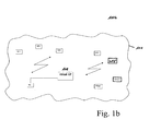
- shows a logical network structure for the home networking system,
- Fig. 2
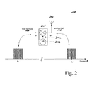
- shows an analog frontend architecture for the modulator/demodulator stage of a
wireless RF transceiver, wherein the same MAC layer is used for the overall
network such that the respective IF signal of an RF signal transmitted via an allocated
RF transmission channel of a wireless local area network is used on the
backbone media and on said wireless local area network,
- Fig. 3
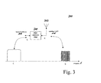
- shows an analog frontend architecture of a wireless RF transceiver with a PHY-layer
conversion stage, wherein the same MAC layer but different PHY layers
are used on the backbone media and on said wireless local area network.
DETAILED DESCRIPTION OF THE PRESENT INVENTION
In the following, one embodiment of the present invention as depicted in Figs. 1a to 3 shall
be explained in detail. The meaning of the symbols designated with reference numerals and
signs in these figures can be taken from an annexed table.
As depicted in Figs. 1a+b, a backbone network 106 having a controlling instance 104 acts
as a virtual access point 108 (AP), and several RF/PHY converters 111a-e are applied to
interconnect a number of distributed wireless (WT1, WT2, WT3, WT4, WT5, WT m +1, and
WT m +2) and/or wired terminals (T m ) via this virtual access point 108. Each of these
RF/PHY converters 111a-e thereby serves a relatively small area (e.g. a single room 102a-e
of a networked building). Together with the associated wired or wireless terminals the virtual
AP 108 builds one overall home networking system 100a which can easily be extended
by adding new RF/PHY converters to the backbone network 106.
If the backbone network 106 uses an OFDM technique, multipath reception is constructively
overlaid at the receiver as long as the different signals arrive within a defined intervall
(the so-called guard intervall). Therefore, the virtual access point 108 can receive and
transmit at different locations (f.e. antennas in different rooms) although the transmitted
signals will have different propagation lenghts on the backbone media.
Therefore each media using OFDM is preferred for the backbone network according to the
present invention. Examples are:
- Powerline Communications
- 5 GHZ WLAN systems (802.11a, HiperLAN2)
- 2.4 GHZ WLAN systems (802.11g)
Depending on the harmonization between the backbone media and the wireless local area
networks 102a,b,c,e, two scenarios for interconnecting distributed wireless terminals (WT1,
WT2, WT3, WT4, WT m +1, WT m+2) and wired communication devices (T m ) to a home networking
system 100a as depicted in Figs. 2 and 3 can be considered:
- If the corresponding IF signal of an RF signal to be transmitted or received via an allocated
RF transmission channel of a wireless LAN 102a,b,c,e is used on the media of the
backbone network 106, a conventional wireless RF transceiver with an analog frontend
architecture comprising a modulator/demodulator 204 with a single up-/down-conversion
stage 204a and a local oscillator 204b can be used for interconnecting said distributed
wireless (WT1, WT2, WT3, WT4, WT5, WT m +1, and WT m +2) and wired terminals
(T m ) via the virtual access point 108 to form a home networking system 100a. This solution
is e.g. applicable for home networking systems where a powerline communication
system serves as home network backbone 106. In this case, the IF spectrum of an RF
signal received via an allocated RF transmission channel of a wireless LAN 102a,b,c,e
is used on the mains. Thereby, the same MAC layer is used for the overall network,
which consists of the wireless LANs 102a,b,c,e and the backbone network 106, such
that the respective IF signal of an RF signal transmitted via an said RF transmission
channel is used on the backbone media and on the respective wireless LANs 102,a,b,c,e.
- In case a PHY-layer signal on said RF transmission channel can not properly be mapped
to a signal on the backbone network 106, a PHY-layer bridging procedure is proposed.
In this scenario, the same MAC layer but different PHY layers are used on the backbone
media and on the respective wireless local area network 102a,b,c,e. Thereby, a wireless
RF transceiver comprising a PHY-layer conversion stage needed for converting the
digital RF signal at the center frequency f1 into the other modulation scheme at the
center frequency f2 or vice versa is introduced to guarantee best possible data transmission
on both media types. The PHY-layer conversion procedure (S5) thereby comprises
the steps of receiving (S5a) an RF signal from a wireless local area network 102a,b,c,e,
allocating (S5b) a backbone medium, converting (S5c) the RF signal from one digital
modulation to another, and transmitting (S5d) the obtained RF signal via the allocated
backbone medium. By contrast, the inverse PHY-layer conversion procedure (S5') is
characterized by the steps of receiving (S5a') a digital signal from a backbone, allocating
(S5b') a single RF transmission channel of a wireless local area network 102a,b,c,e
through a wireless PHY converting stage 112a-e, converting (S5c') the signal from one
modulation scheme to the other and transmitting (S5d') the obtained RF signal via the
allocated RF transmission channel.
Note that both digital modulation schemes may use bands in the RF range rather than converting
to the IF range as proposed in the first embodiment.
Independent of the respective scenario, the present invention allows the usage of one common
MAC layer that is controlled by a
central backbone controller 104 which allows most
simple integration of all possible home network media elements. Said
backbone network
106 thereby appears to the outside world as a single all-controlling instance. Other media
types can be connected to the
backbone network 106 by using a special device with a protocol
stack having an appropriate convergence layer on top, which acts as a terminal within
the
backbone network 106.
| Depicted Features and their Corresponding Reference Signs |
| No. | Technical Feature (System Component or Procedure Step) |
| 100a | home networking system which is constituted by a number of wired (102d) and wireless LANs (102a,b,c,e) connected to a backnone network 106, said home networking system 100a comprising a number of wireless terminals WT1, WT2, WT3, WT4, WT5, WT m +1, WT m +2 and one wired communication device T m interconnected via a virtual access point (AP) |
| 100b | logical network structure for the home networking system 100a |
| 101 | coverage area of a home network environment with interconnected wireless (WT1, WT2, WT3, WT4, WT5, WT m +1, and WT m +2) and wired communication devices (T m ) |
| 102a | room #1 of a networked building in the coverage area of a wireless home networking system 100a, wherein two wireless terminals (WT1 and WT2) are connected to a backbone network 106 via a first RF/PHY converter stage 111a |
| 102b | room #2 of the networked building in the coverage area 101 of the wireless home networking system 100a, wherein one wireless terminal (WT3) is connected to the backbone network 106 via a second RF/PHY converter stage 111b |
| 102c | room #3 of the networked building in the coverage area of the wireless home net-working system 100a, wherein two wireless terminals (WT4 and WT5) are connected to the backbone network 106 via a third RF/PHY converter stage 111c |
| 102d | room #n of the networked building in the coverage area of the wireless home net-working system 100a, wherein one wired communication device T m is connected to the backbone network LAN 106 via a wired backbone access node 109 |
| 102e | room #(n+1) of the networked building in the coverage area of the wireless home net-working system 100a, wherein two wireless terminals WT m +1 and WT m +2 are connected to the backbone network 106 via a fourth RF/PHY converter stage 111e |
| 104 | controlling instance of the network system, connected to the backbone network 106 |
| 106 | backbone network interconnecting a number of wireless (111a-e) and/or wired backbone access nodes (109) of the home networking system 100a |
| 108 | virtual access point, consisting of the backbone network 106 and a number of interconnected wireless (111a-e) and/or wired backbone access nodes (109) |
| 109 | wired backbone access node, which connects the wired communication device T m located in room #n to the backbone network 106 |
| 110a | Tx/Rx antenna of a first wireless RF transceiver 112a |
| 110b | Tx/Rx antenna of a second wireless RF transceiver 112b |
| 110c | Tx/Rx antenna of a third wireless RF transceiver 112c |
| 110e | Tx/Rx antenna of a fourth wireless RF transceiver 112e |
| 111a | RF/PHY converter stage of the first wireless RF transceiver 112a, which connects the wireless terminals WT1 and WT2 located in room #1 to the backbone network106 |
| 111b | RF/PHY converter stage of the second wireless RF transceiver 112b, which connects the wireless terminal WT3 located in room #2 to the backbone network 106 |
| 111c | RF/PHY converter stage of the third wireless RF transceiver 112c, which connects the wireless terminals WT4 and WT5 located in room #3 to the backbone network 106 |
| 111e | RF/PHY converter stage of the fourth wireless RF transceiver 112e, which connects the wireless terminals WT m +1 and WT m +2 located in room #(n+1) to the backbone network 06 |
| 112a | first wireless RF transceiver 112a, located in room #1 of the networked building |
| 112b | second wireless RF transceiver 112b, located in room #2 of the networked building |
| 112c | third wireless RF transceiver 112c, located in room #3 of the networked building |
| 112d | fourth wireless RF transceiver 112d, located in room #(n+1) of the networked building |
| 200 | analog front end architecture for the combined modulator/demodulator stage of a wireless RF transceiver needed for a down-conversion of an RF signal received via an allocated RF transmission channel of a wireless local area network 102a,b,c,e from an RF band to an intermediate frequency (IF) band or an up-conversion of an IF signal to be transmitted from the IF band to an RF band, wherein the same MAC layer is used for the overall network such that the respective IF signal of an RF signal transmitted via an allocated RF transmission channel of a wireless local area network 102a,b,c,e is used on the backbone media and on the wired backbone network 106 |
| 202 | Tx/Rx antenna of the wireless RF transceiver |
| 204 | modulator/demodulator stage of the wireless RF transceiver |
| 204a | up-/down-conversion mixer of the modulator/demodulator stage 204 |
| 204b | local oscillator of the modulator/demodulator stage, which provides an approximately sinusoidal oscillator signal |
| 300 | analog frontend architecture of a wireless RF transceiver with a PHY-layer conversion stage needed for a PHY-layer conversion of an RF signal received via an allocated RF transmission channel of a wireless local area network 102a,b,c,e from an RF band at a center frequency f 2 to another center frequency f 1 or vice-versa, wherein the same MAC layer but different PHY layers are used on the backbone media and on the wireless local area networks 102a,b,c,e |
| 302 | Tx/Rx antenna of the wireless RF transceiver |
| 304 | PHY-layer conversion stage of the wireless RF transceiver |
| µC | central backbone controlling instance (µC) of the backbone network 106, which controls the common media access control (MAC) layer |
| S0a | step #0a: allocating a number of wired and/or wireless transmission channels |
| S0b | step #S0b: bridging between home network media elements of different multimedia data types on allocated transmission channels at a predefined layer of the underlying protocol stack |
| S1 | step #1: using a common media access control (MAC) layer for the entire home net-working system 100a needed for accessing different backbone media of the wired backbone network 106 |
| S2 | step #2: accessing backbone media of the backbone network 106 |
| S2' | step #2': integrating home network media elements of different multimedia data types interconnected by said home networking system 100a |
| S3 | step #3: using different physical (PHY) layers on the backbone media and on the wireless local area networks 102a,b,c,e |
| S4 | step #4: mapping the PHY-layer representation of an RF signal transmitted via an allocated RF transmission channel of a wireless local area network 102a,b,c,e to an IF signal on a backbone medium of the wired backbone network 106 |
| S5 | step #5: PHY-layer conversion procedure |
| S5' | step #5': inverse PHY-layer conversion procedure |
| S5a | step #5a: receiving an RF signal from a wireless local area network 102a,b,c,e |
| S5b | step #5b: allocating a backbone medium connected to the backbone network 106 |
| S5c | step #5c: down-converting the RF signal from an RF band to a corresponding IF band |
| S5d | step #5d: transmitting the obtained IF signal via the allocated backbone medium |
| S5a' | step #5a': receiving an IF signal from a backbone medium connected to the backbone network 106 |
| S5b' | step #5b': allocating a single RF transmission channel of a wireless local area network 102a,b,c,e connected to the wired Ethernet LAN 106 via a wireless access point 112a-e |
| S5c' | step #5c': up-converting the IF signal from the IF band to a corresponding RF band |
| S5d' | step #5d': transmitting the obtained RF signal via the allocated RF transmission channel |