EP1508997A2 - Verfahren und Vorrichtung zur automatischen Lokalisierung eines Leistungsproblems in einem Netzwerk - Google Patents
Verfahren und Vorrichtung zur automatischen Lokalisierung eines Leistungsproblems in einem Netzwerk Download PDFInfo
- Publication number
- EP1508997A2 EP1508997A2 EP04253972A EP04253972A EP1508997A2 EP 1508997 A2 EP1508997 A2 EP 1508997A2 EP 04253972 A EP04253972 A EP 04253972A EP 04253972 A EP04253972 A EP 04253972A EP 1508997 A2 EP1508997 A2 EP 1508997A2
- Authority
- EP
- European Patent Office
- Prior art keywords
- network
- paths
- path
- flow matrix
- performance
- Prior art date
- Legal status (The legal status is an assumption and is not a legal conclusion. Google has not performed a legal analysis and makes no representation as to the accuracy of the status listed.)
- Withdrawn
Links
Images


Classifications
-
- H—ELECTRICITY
- H04—ELECTRIC COMMUNICATION TECHNIQUE
- H04L—TRANSMISSION OF DIGITAL INFORMATION, e.g. TELEGRAPHIC COMMUNICATION
- H04L43/00—Arrangements for monitoring or testing data switching networks
-
- H—ELECTRICITY
- H04—ELECTRIC COMMUNICATION TECHNIQUE
- H04L—TRANSMISSION OF DIGITAL INFORMATION, e.g. TELEGRAPHIC COMMUNICATION
- H04L41/00—Arrangements for maintenance, administration or management of data switching networks, e.g. of packet switching networks
- H04L41/06—Management of faults, events, alarms or notifications
- H04L41/0631—Management of faults, events, alarms or notifications using root cause analysis; using analysis of correlation between notifications, alarms or events based on decision criteria, e.g. hierarchy, tree or time analysis
-
- H—ELECTRICITY
- H04—ELECTRIC COMMUNICATION TECHNIQUE
- H04L—TRANSMISSION OF DIGITAL INFORMATION, e.g. TELEGRAPHIC COMMUNICATION
- H04L43/00—Arrangements for monitoring or testing data switching networks
- H04L43/50—Testing arrangements
-
- H—ELECTRICITY
- H04—ELECTRIC COMMUNICATION TECHNIQUE
- H04L—TRANSMISSION OF DIGITAL INFORMATION, e.g. TELEGRAPHIC COMMUNICATION
- H04L41/00—Arrangements for maintenance, administration or management of data switching networks, e.g. of packet switching networks
- H04L41/50—Network service management, e.g. ensuring proper service fulfilment according to agreements
- H04L41/5003—Managing SLA; Interaction between SLA and QoS
-
- H—ELECTRICITY
- H04—ELECTRIC COMMUNICATION TECHNIQUE
- H04L—TRANSMISSION OF DIGITAL INFORMATION, e.g. TELEGRAPHIC COMMUNICATION
- H04L43/00—Arrangements for monitoring or testing data switching networks
- H04L43/08—Monitoring or testing based on specific metrics, e.g. QoS, energy consumption or environmental parameters
- H04L43/0823—Errors, e.g. transmission errors
- H04L43/0829—Packet loss
-
- H—ELECTRICITY
- H04—ELECTRIC COMMUNICATION TECHNIQUE
- H04L—TRANSMISSION OF DIGITAL INFORMATION, e.g. TELEGRAPHIC COMMUNICATION
- H04L43/00—Arrangements for monitoring or testing data switching networks
- H04L43/08—Monitoring or testing based on specific metrics, e.g. QoS, energy consumption or environmental parameters
- H04L43/0852—Delays
-
- H—ELECTRICITY
- H04—ELECTRIC COMMUNICATION TECHNIQUE
- H04L—TRANSMISSION OF DIGITAL INFORMATION, e.g. TELEGRAPHIC COMMUNICATION
- H04L43/00—Arrangements for monitoring or testing data switching networks
- H04L43/08—Monitoring or testing based on specific metrics, e.g. QoS, energy consumption or environmental parameters
- H04L43/0852—Delays
- H04L43/087—Jitter
-
- H—ELECTRICITY
- H04—ELECTRIC COMMUNICATION TECHNIQUE
- H04L—TRANSMISSION OF DIGITAL INFORMATION, e.g. TELEGRAPHIC COMMUNICATION
- H04L43/00—Arrangements for monitoring or testing data switching networks
- H04L43/16—Threshold monitoring
Definitions
- Serial No. 10/270,011 entitled “Report Generation and Visualization Systems and Methods and Their Use in Testing Frameworks for Determining Suitability of a Network for Target Applications”
- Serial No. 10/270,122 entitled “Network Traffic Generation and Monitoring Systems and Methods for Their Use in Testing Frameworks for Determining Suitability of a Network for Target Applications” all of which were filed on October 15, 2002, the disclosures of which are incorporated by reference herein.
- the invention relates generally to network monitoring and analysis systems, and more particularly to techniques for the monitoring and analysis of Voice over Internet Protocol (VoIP) communications, multimedia communications or other types of network traffic in a network-based communication system.
- VoIP Voice over Internet Protocol
- the invention addresses the above-noted need by providing techniques for automatically determining the particular locations associated with performance problems in a network of a network-based communication system comprising a plurality of endpoint devices.
- a network monitoring and analysis system is configured to include a root cause analysis function that permits the automatic determination of performance problem locations in the network.
- Test communications are generated in accordance with a selected pattern, and end-to-end path measurement data is collected utilizing the generated test communications.
- the test communications may be directed between pairs of the endpoint devices as specified in the selected pattern.
- the end-to-end path measurement data is transformed to produce a plurality of performance indicators comprising a performance indicator for each of a plurality of non-end-to-end paths defined at least in part by the selected pattern.
- the end-to-end path measurement data is transformed into the plurality of link-level performance indicators in this embodiment by utilizing y and A to solve the equation for x . This process may be repeated for each of a plurality of time intervals.
- the selected pattern is defined by a flow matrix having rows representing end-to-end paths for which measurement data is collected, and columns representing single-link or multiple-link non-end-to-end paths for which performance indicators are determined.
- the flow matrix may comprise an n ⁇ m matrix wherein for 0 ⁇ i ⁇ n and 0 ⁇ j ⁇ m, m i,j denotes the number of times the end-to-end path in row i traverses the non-end-to-end path in column j .
- the selected pattern is determined at least in part based on a reduced network topology generated by applying a network topology reduction process to a graph representative of a topology of the network.
- the network topology reduction process determines one or more non-end-to-end paths within the network which carry the same traffic flow.
- a flow matrix selection algorithm may be applied to the reduced network topology.
- the flow matrix selection algorithm preferably maintains a list of end-to-end paths and processes the list such that a plurality of non-end-to-end paths for which performance indicators can be generated is determined.
- the flow matrix selection algorithm may also be configurable to accept one or more constraints on selection of particular paths in generating a given flow matrix.
- the present invention in the illustrative embodiment provides a particularly efficient and accurate mechanism for generating link-level performance indicators in a network-based communication system, thereby permitting a better understanding of QoS behavior in the network.
- IP Internet protocol
- the invention although particularly well-suited for use in monitoring and analysis of VoIP traffic, also provides significant advantages in multimedia traffic applications or other flow-based real-time applications in which it is desirable to understand link-level performance within the network.
- the invention can thus be used with voice, video, multimedia or any other type of network traffic in a network-based communication system.
- packet as used herein is intended to include not only IP packets but also other types of packets used in other packet-based communication systems.
- call as used herein is intended to be construed broadly so as to encompass Internet telephony communications, VoIP communications, Session Initiation Protocol (SIP) communications, multimedia communications, or other types of network traffic in a network-based communication system.
- VoIP Voice over IP
- SIP Session Initiation Protocol
- endpoint and “endpoint device” are used interchangeably herein and are intended to include an origination or destination device associated with a given VoIP call or other type of communication in a network-based communication system.
- a given endpoint device therefore need not be a terminal device of the system, and may comprise an internal network element such as, for example, a gateway, a router, a switch, or any other type of non-terminal network element.
- a given pair of endpoint devices in the illustrative embodiment may be viewed generally as comprising the source and destination nodes of a particular communication path.
- An endpoint device may therefore be a device comprising or otherwise associated with any network node.
- measurement data is intended to include jitter, loss, delay or other QoS-related statistics, associated analysis results determinable therefrom, as well as other types of data.
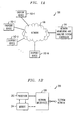
- FIG. 1A shows an example network-based communication system 100 in which the present invention is implemented.
- Each of the endpoint devices 102 and the controller 104 is coupled to or otherwise associated with a network 106.
- the variables j and M are used in a different sense in the context of FIG. 1A than elsewhere in the description.
- one or more of the endpoint devices of the system may comprise or be otherwise associated with an internal node of network 106.
- An illustrative embodiment of the invention as implemented in the network-based communication system 100 of FIG. 1A advantageously permits automated determination of the particular location(s) associated with one or more performance problems in the network 106.
- This function is generally referred to herein as "root cause analysis,” and is a type of function that may also be referred to as “blame attribution.”
- the controller 104 may illustratively comprise an otherwise conventional controller of a network monitoring and analysis system, implemented in or otherwise utilized in conjunction with the system 100, suitably modified to include a root cause analysis function in accordance with the invention, as will be described in detail below.
- network monitoring and analysis system is intended to include a network monitoring system, a network analysis system, or a system capable of both network monitoring and network analysis.
- One example of a network monitoring and analysis system that may be configured to include a root cause analysis function in accordance with the invention is the ExpertNetTM network readiness assessment tool commercially available from Avaya Inc. of Basking Ridge, New Jersey, USA.
- the ExpertNetTM tool may be configured to collect various measurements from a network, including, by way of example, topology information, periodic traffic measurements from network devices via Simple Network Management Protocol (SNMP), and end-to-end performance measurements collected with the use of software agents installed at various endpoint devices or elsewhere in the network.
- SNMP Simple Network Management Protocol
- end-to-end performance measurements collected with the use of software agents installed at various endpoint devices or elsewhere in the network The conventional aspects of this tool and other network monitoring and analysis systems are well-known in the art, and therefore will not be further described herein.
- Such systems may be implemented at least in part in the form of software running on a computer or other processing device associated with the controller 104.
- system 100 is shown as including a centralized controller 104 in FIG. 1A, this should not be construed as a requirement of the invention.
- the invention can alternatively be implemented using a distributed monitoring and analysis system as described in the above-cited U.S. Patent Application Serial No. 10/459,948, or using a combination of centralized and distributed techniques.
- the functions of the controller 104 may be distributed at least in part across one or more of the endpoint devices, and/or associated distributed test units.
- controller as used herein is therefore intended to include a centralized controller, a distributed controller, or a hybrid controller which is at least partially centralized and at least partially distributed.
- the endpoint devices 102 may be otherwise conventional wired or wireless IP telephones (including devices commonly referred to as IP “softphones"), personal digital assistants (PDAs), mobile telephones, personal computers (PCs), single-board computers (SBCs) or other types of processing devices, suitably configured for interaction with the controller 104 in providing various functions of the network monitoring and analysis system.
- IP Internet Protocol
- PDAs personal digital assistants
- PCs personal computers
- SBCs single-board computers
- endpoint devices 102 are each typically configured to operate as both receiver and transmitter, as in the case of a bidirectional VoIP communication established between a given pair of endpoints.
- One or more of the endpoint devices 102 may comprise so-called “synthetic" devices which generate test communications in the form of synthesized calls but are not configured for use in placing actual calls. Also, one or more of the endpoint devices may comprise devices suitable for use in placing actual calls and also capable of generating test communications in the form of synthesized calls. Additional details regarding devices of the latter type can be found in the above-cited U.S. Patent Application Serial No. 10/261,431.
- Additional system elements may be coupled between each of the endpoints 102 and the network 106, or otherwise arranged within the system 100, in accordance with conventional practice.
- Network 106 may represent, e.g., a global communication network such as the Internet, a wide area network, a metropolitan area network, a local area network, a wireless cellular network, a public switched telephone network (PSTN), or a satellite network, as well as portions or combinations of these or other communication networks.
- the network 106 may comprise conventional IP routers, gateways, switches or other packet processing elements.
- the network may include a DEFINITY® Enterprise Communication Service (ECS) communication system switch available from Avaya Inc. of Basking Ridge, New Jersey, USA.
- ECS DEFINITY® Enterprise Communication Service
- Another example call processing switch suitable for use in conjunction with the present invention is the MultiVantageTM communication system switch, also available from Avaya Inc.
- Standard protocols that are commonly utilized in VoIP communications include User Datagram Protocol (UDP), described in Internet Engineering Task Force (IETF) Request for Comments (RFC) 768, "User Datagram Protocol," August 1980, http://www.ietf.org/rfc/rfc768.txt, Real-Time Transport Protocol (RTP), described in IETF RFC 1889, “RTP: A Transport Protocol for Real-Time Applications,” http://www.ietf.org/rfc/rfc1889.txt, and RTP Control Protocol (RTCP), described in IETF RFC 3158, “RTP Testing Strategies," August 2001, all of which are hereby incorporated by reference herein.
- UDP User Datagram Protocol
- RFC Real-Time Transport Protocol
- RTCP Real-Time Transport Protocol
- RTCP Real-Time Control Protocol
- VoIP communications may comprise RTP voice data packets that are sent over an IP network using UDP. More particularly, the RTP packets are encapsulated in UDP packets which are themselves encapsulated in IP packets.
- Session Initiation Protocol Session Initiation Protocol
- ITU-T International Telecommunication Union - Telecommunication Standardization Sector
- VoIP communications or other communications in the context of the present invention may be implemented utilizing one or more of the above-cited protocols, or other suitable protocols, as will be readily apparent to those skilled in the art.
- system 100 may include additional endpoints, comprising other types and arrangements of routing elements, switching elements or other types of processing elements.
- FIG. 1B shows one possible implementation of a given processing element 200 of the FIG. 1A system.
- the processing element 200 may represent, by way of example, at least a portion of a given one of the endpoint devices 102, at least a portion of the controller 104, or at least a portion of another processing device of the system.
- the processing element 200 as shown in the figure includes a processor 202 coupled to a memory 204 and one or more network interfaces 206.
- the techniques of the present invention may be implemented at least in part in the form of software storable in the memory 204 and executable by the processor 202.
- the memory 204 may represent random access memory (RAM), read-only memory (ROM), optical or magnetic disk-based storage, or other storage elements, as well as combinations thereof.
- FIG. 1B As shown for illustrative purposes may be combined into or distributed across one or more processing devices, e.g., a microprocessor, an application-specific integrated circuit (ASIC), a computer or other device(s).
- processing devices e.g., a microprocessor, an application-specific integrated circuit (ASIC), a computer or other device(s).
- ASIC application-specific integrated circuit
- the processing element 200 may include conventional elements typically associated with such a device, such as codecs and other voice signal processing hardware or software elements.
- the illustrative embodiment of the invention as implemented in the network-based communication system 100 of FIG. 1A utilizes endpoints 102 and controller 104 to provide a root cause analysis function in a network monitoring and analysis system.
- the root cause analysis function will now be introduced with reference to FIGS. 2A and 2B. Additional details of the associated processing operations, including a number of examples, will then be described with reference to FIGS. 3 through 16.
- a root cause analysis function in the illustrative embodiment includes a call selection step 210, an assessment step 212, and a transformation step 214, and produces output information 220 that identifies the particular location(s) associated with one or more performance problems in the network 106.
- Selection step 210 involves selection of an appropriate set of calls to be placed in the system 100 in conjunction with the root cause analysis function.
- the selected set of calls is an example of what is more generally referred to herein as a "selected call pattern,” or even more generally as a "selected pattern.”
- step 212 the selected calls are placed, or "exercised,” as part of a network assessment operation of the network monitoring and analysis system, with each call generally being placed between a corresponding pair of endpoint devices 102 of the system 100.
- the resulting end-to-end (E2E) measurements comprising measurement data characterizing the selected calls, are then transformed to link-level indicators in step 214.
- the root cause analysis function in the illustrative embodiment yields the output information 220, which includes a set of paths 222 and a corresponding set of performance indicators 224.
- the set of paths 222 includes an identifier for each of n links, denoted Link 1, Link 2, ... Link n .
- the set of performance indicators 224 includes, for each of the links, a corresponding performance indicator.
- the performance indicators are binary in nature, taking on one of two values, namely, "Clean” to indicate a link that is not associated with a performance problem, and "Problem" to indicate a link that is associated with a performance problem.
- Link 2 is shown as having the "Problem” indicator, and is thus associated with a performance problem, while Link 1 and Link n are each denoted as “Clean.”
- the indicators may be determined based on a user-defined threshold of acceptable performance, or using other types of thresholding arrangements.
- the particular thresholds used in a given implementation of the invention are generally dependent upon the application, and can be determined in a straightforward manner, as will be readily apparent to those skilled in the art.
- FIG. 2A It is to be appreciated that the particular arrangement of processing steps and the output information configuration of FIG. 2A is presented by way of illustrative example only. Numerous alternative arrangements of processing steps and output information configuration may be used in implementing the invention, and the invention is not limited in this regard.
- link and “path” may each be used herein refer to a communication channel or other connection between network nodes, as in the output information 220 of FIG. 2A.
- a path may also be generally viewed as comprising a sequence of multiple links.
- a given end-to-end path between a pair of the endpoints 102 in FIG. 1A may be generally viewed as comprising a sequence of multiple links.
- the term "path” will typically be used in this latter sense, that is, as a sequence of links, while a "link” will be considered a path of unity length. Therefore, in this context, a given link is considered a path, but a given path may not be considered a link.
- An important objective in the illustrative embodiment is to assign performance estimates to links or groups of links in the network.
- a single bottleneck link may cause performance problems on any end-to-end path traversing the link.
- a number of bottlenecks can show symptoms throughout the network.
- the amount of effort required to locate the bottlenecks as well as their scale may be significant depending on the network topology.
- the illustrative embodiment automates this task by providing a particularly efficient mechanism for understanding the link-level behavior in the network. For example, based on a user-defined threshold of acceptable performance, those links that have unacceptable levels may be identified, and then further investigated to better understand the nature of the problems. This ability to accurately pinpoint the network regions with unacceptable performance levels constitutes an important advantage of the invention.
- the network topology is available and software agents are installed throughout the network that can collect end-to-end performance measurements such as end-to-end delay, jitter, and packet loss.
- end-to-end performance measurements such as end-to-end delay, jitter, and packet loss.
- these features may be provided using the ExpertNetTM tool.
- Other types of network monitoring and analysis systems may be used.
- the approach utilized in the illustrative embodiment begins by analyzing the network topology with respect to the locations of software agents for collecting measurements. We generally attempt to search the network topology for an optimum set of network paths that can be assigned performance estimates. More specifically, an example algorithm is provided below that analyzes the network topology and provides a set of paths to which performance estimates can be assigned. Note that, informally, the optimum set is the one composed of paths that are as short and as disjoint as possible. It can be shown that when the network topology is a tree, this example algorithm determines the optimum set of paths, although the invention can of course be implemented using other algorithms that do not exhibit this property.
- the approach applied in the illustrative embodiment considers the physical network topology, it is expected that the topology is either a tree or close to being a tree. In cases where an optimum solution is costly, a set of paths may be selected that is a low cost approximation but potentially decreases the accuracy of the approach. Then, we determine where in the network to collect end-to-end path measurements such that we can determine performance estimates for the paths in the selected set. The end-to-end path measurements are then collected, using the above-noted ExpertNetTM tool or other similar system. Finally, the collected data is analyzed in light of the topology in order to infer performance estimates on links or groups of links.
- G (D, L) be a connected network topology graph where D is a set of nodes and L is a set of links. Each device in D is a network element such as a router or switch. Let D 1 and D 2 be two distinct devices in D. There is a link between D 1 and D 2 if and only if there is a direct communication path between D 1 and D 2 .
- a path in G is a sequence of links from L.
- the length of a path p denoted as length ( p ), is the number of links on p.
- a link is a path of length 1.
- the symbol ⁇ denotes a path of length 0.
- x and y in G such that the last node of x is the same as the first node ofy, x .
- y denotes the path formed by the concatenation ofx and y in G .
- FIG. 3 illustrates an example set of network elements involved in a sample voice call between endpoints A and B . It is assumed that each of these endpoints can initiate and respond to Internet telephony voice calls by generating corresponding RTP streams. Also, the endpoints are assumed to be configured to measure the QoS statistics pertaining to the RTP streams. We refer to the end-to-end traffic between A and B as a flow.
- the path from A to B is the reverse of the path from B to A.
- a line between two devices denotes a bidirectional edge.
- the voice packets pass through routers indicated as D 1 , D 2 , and D 3 in FIG. 3.
- the router interfaces that the packets traverse are also marked on the figure with circles.
- the call path is L 1 . L 2 .
- a device in G that has an endpoint attached is referred to as a leaf.
- Set E ⁇ D denotes the set of leaves in G.
- D 1 and D 3 are the leaves.
- path L 1 .L 2 is an end-to-end path.
- a set P for a given G and E denotes the set of all end-to-end paths in G between devices in E.
- Set P is computed from G and E . Therefore, in the illustrative embodiment, the part of the topology that we can collect measurements from lies between the endpoints, and is defined by the set P .
- Matrix notation will be used to represent the network topology and the end-to-end path information.
- a matrix where rows denote end-to-end paths and columns denote sequences of links (or paths) in G is an example of what is referred to herein as a flow matrix.
- M be an n ⁇ m flow matrix. For 0 ⁇ i ⁇ n and 0 ⁇ j ⁇ m, m i,j denotes the number of times the end-to-end path in row i traverses the path in column j .
- a given flow matrix utilizable in accordance with the invention may be a singular matrix or a non-singular matrix.
- the row and column entries thereof are thus not required to have any particular form.
- a flow matrix formed by P and L is considered the complete flow matrix for G and E .
- FIG. 5 shows two example flow matrices for the example network of FIG. 4.
- Flow matrix 1 corresponds to end-to-end paths P 1 and P 2 .
- Flow matrix 2 corresponds to end-to-end paths P 1 , P 2 , and P 3 .
- a call pattern in the illustrative embodiment comprises a list of endpoint pairs.
- measurements are concurrently collected from a given network, pertaining to end-to-end paths between the endpoint pairs in the list.
- the call pattern may have other information pertaining to the measurements such as duration, repetition rate and the like. For simplicity of description it will be assumed that exercising a call pattern corresponds to collecting substantially simultaneous performance metrics from the network for a given user-defined duration.
- call pattern ⁇ ( e 1 , e 2 ), ( e 1 , e 3 ) ⁇ corresponds to flow matrix 1.
- call pattern ⁇ ( e 1 , e 2 ), ( e 1 , e 3 ), ( e 2 , e 3 ) ⁇ corresponds to flow matrix 2.
- Exercising a call pattern generally involves collecting substantially simultaneous measurements from the network. This is preferred in the illustrative embodiment, where it has been assumed that packets traversing distinct end-to-end paths p 1 and p 2 at a given time receive the same QoS on intersecting segments of p 1 and p 2 .
- the present invention in the illustrative embodiment collects end-to-end path measurements from the network under consideration at regular time intervals and then uses the measurements to infer link-level performance estimates at each time interval. Measurement collection is implemented by inj ecting synthetic traffic between endpoints in the network. Note that the time interval length is an adjustable parameter that depends on how frequently one would like to sample the network.
- the flow matrix A specifies the paths for which performance metrics can be determined. Hence, it is preferable to ensure that the columns of flow matrix A correspond to paths that are as short and as disjoint as possible. Furthermore, A is typically singular.
- the call pattern and the corresponding flow matrix impact the granularity of the link-level estimates.
- the average delay incurred on each link at a given time interval be x 1 , x 2 , x 3 , x 4 for L 1 , L 2 , L 3 , L 4 , respectively.
- x 1 + x 2 + x 3 and x 1 + x 4 representing average delay attributable to paths L 1 . L 2 . L 3 and L 1 . L 4 , respectively, can be estimated.
- x 1 , x 2 + x 3 and x 4 representing average delay attributable to paths L 1 , L 2 .
- L 3 , and L 4 can be estimated. This determination is illustrated by the equations shown in FIG. 6. As is apparent from the figure, the columns of the flow matrix represent the non-end-to-end paths for which performance estimates can be determined. Such non-end-to-end paths may comprise single-link or multiple-link paths.
- the selection of a call pattern and its corresponding flow matrix is therefore an important issue in the illustrative embodiment of the invention. This issue will be addressed in greater detail below. Since the flow matrix determines the call pattern, the call pattern selection process may also be referred to herein as flow matrix selection.
- a sequence of links is defined as a pipe if each link in the sequence carries the same flow.
- Set I for a given G and E denotes the set of pipes for a given G and E.
- a pipe is a path.
- FIG. 7 shows an algorithm Generate_Pipes that computes the pipe set, I , for a given topology, G and an endpoint set, E.
- the algorithm starts by constructing P, the set of all end-to-end paths between devices in E.
- M be the complete flow matrix for G with respect to E.
- the algorithm then groups links in L into disjoint sets such that all links in a given set have the same column vector in M.
- S ⁇ S 1 , S 2 , ... S k ⁇ be the result of this grouping, assuming there are k distinct column vectors in M , with sets of sets being denoted in boldface. Note that each element S i of S is the set of links that carry the same flow.
- the algorithm constructs a path for each S i that corresponds to the concatenation of links in S i .
- the path for each S i is added to I .
- links grouped into a set may not be consecutive to form a path. In such cases, each link is considered a pipe by itself and added individually to I . This could occur if there is a cycle in the topology.
- FIG. 8 illustrates a case where there is a loop in the graph.
- D 4 is a router and the rest of the devices in the topology are switches.
- the path between endpoints e 1 and e 2 is L 1 . L 2 and the path between e 1 and e 3 is L 1 . L 3 . L 3 . L 2 .
- endpoints e 1 and e 2 are on the same virtual local area network (VLAN) and endpoint e 3 is on a different VLAN than e 1 and e 2 .
- VLAN virtual local area network
- endpoint e 3 is on a different VLAN than e 1 and e 2 .
- D 4 is a router that switches between VLANs.
- the complete flow matrix for this example is also shown in the figure.
- the last part of the algorithm Generate_Pipes ensures that links L 1 and L 2 are not placed in the same pipe even though they have the same column vectors in M as shown in FIG. 9.
- the reduced topology G ' is the same as G since the pipe set I is the same as the link set L .
- FIG. 8 is an example only, and the invention can be implemented using other algorithms which operate in a different manner.
- E is the same for G and G' since all leaf nodes are included in the reduced topology graph.
- the topology graph is connected after the reduction.
- Set P' for a given G' and E denotes the set of all end-to-end paths in G' between devices in E.
- Call pattern selection in this embodiment generally involves selecting a flow matrix with certain desirable properties.
- additive QoS metrics such as delay and loss will be assumed, such that the end-to-end metric corresponds to the sum of individual link-level metrics on the path.
- a logarithmic model will be used for loss.
- a set of paths is considered minimal if no path in the set contains another member of the set as a proper subpath.
- FIG. 10 shows two example flow matrices for the example network of FIG. 9, namely, flow matrix 1 with paths P 1 and P 2 and flow matrix 2 with paths P 1 , P 2 , and P 3 .
- the minimal set of estimable paths is ⁇ L 1 . L 2 , L 1 . L 3 ⁇ .
- the minimal set of estimable paths is ⁇ L 1 , L 2 , L 3 ⁇ .
- Set W for a given G and P , is the minimal set of paths where each member path is estimable and the union of links on all member paths is L .
- W for a given G and E is a minimal set. Furthermore, there does not exist a path p in any set of estimable paths for a given G and E , such that p that is a proper subpath of a path in W.
- W ⁇ L 1 , L 2 , L 3 ⁇ .
- a flow matrix M for G ' and E is optimum if the columns of M are formed by the paths in W, and there does not exist a flow matrix M' such that columns of M' are the paths in W and number of rows of M' is less than the number of rows of M .
- an optimum flow matrix is non-singular.
- the call pattern selection strategy in the illustrative embodiment searches for optimum flow matrices.
- I W .
- W ⁇ L 1 . L 2 . L 3 , L 1 . L 4 . L 6 , L 3 . L 5 . L 6 ⁇ , same as the end-to-end paths.
- FIG. 12 shows two flow matrices and the minimal set of paths that can be estimated using each flow matrix.
- a simple algorithm for flow matrix selection is one which gradually builds a non-singular flow matrix.
- M be a flow matrix constructed by adding rows corresponding to paths in P' .
- a path p in P' gets selected if adding a new row corresponding to p increases the rank of M .
- the algorithm stops when all paths are processed.
- an obstacle arises in this algorithm in determining what constitutes the columns in M .
- One choice is the set of pipes, but in this case the algorithm still has to determine the minimal set of estimable paths for the given topology and endpoint set.
- a further issue pertains to satisfying various constraints in flow matrix selection.
- the simple algorithm cannot handle cases where there are other constraints on matrix selection such as ensuring that certain pipes in the network are estimable. There is a need to determine if a given path is estimable for a given G ' and P' .
- FIG. 14 shows an algorithm Select_Matrix that addresses the issues described above.
- the algorithm provides a heuristic for generating a flow matrix for a given G' and E.
- W denotes the columns and R denotes the rows in the flow matrix.
- the example algorithm of FIG. 14 is guaranteed to produce a flow matrix whose columns are the paths in W for G' and E .
- the present invention can be implemented using other algorithms which do not produce this particular result.
- the example algorithm of FIG. 14 maintains a list of paths, denoted herein as open, which contains paths with no estimable parts. As pipes become estimable during the course of the computation, each path p in open is modified by removing estimable pipes from p. The original end-to-end path for each path in open is maintained.
- P' for input G' and E is computed and open is initialized to P'.
- the algorithm first removes a path p from open. Then for each pipe c i on p , it searches open for a set of paths S that can estimate c i . If such a set S is not found, that means c i is not estimable so c i is appended to the next pipe on the path. The next pipe processed becomes c i . c i +1 . If, however, c i is estimable by set S, then c i is added to W.
- S' be the set of original paths pertaining to paths in S. S' is added to R.
- open is updated to reflect the fact that c i is now estimable. This involves removing c i from all paths in open. After this operation, open is sorted so that partial paths, i.e., those that have been reduced earlier, are moved to the top and will have preference for processing. When all pipes on p are processed, p is removed from open .
- the box labeled as B1 in FIG. 14 denotes the algorithm step where the computation of estimating set S for c i occurs.
- FIG. 15 illustrates three basic patterns for estimating pipe c i . Dashed lines in the figure indicate paths that are in the topology but not immediately relevant to the argument. This step searches the paths in open to determine whether any of the three patterns above apply to paths in open.
- each end-to-end path corresponding to a row of the flow matrix selected by algorithm Select_Matrix corresponds to a unique endpoint pair.
- the pairs whose paths correspond to the flow matrix are selected as the call pattern to be used for data collection.
- algorithm Select_Matrix may be modified to take into consideration that paths are selectable only if they satisfy the required conditions. This may be accomplished by modifying box B 1 in the algorithm Select_Matrix by adding additional constraints. Assume it is required that each endpoint participates in a maximum of N calls at the same time. This implies that an endpoint can appear maximum of N times in the selected call pattern. In this case, additional data structures associated with a path can maintain information about the call pattern. After the selection of each path (e.g., participating in S ) these structures are updated to reflect the new addition to the call pattern. Other constraints may be accommodated by modifying the function implemented in box B1. Note that when constraints are imposed on call pattern selection, an optimum flow matrix may not be selected.
- Network measurements may be collected by substantially simultaneously injecting synthetic traffic between the endpoints in the selected call pattern.
- data collection occurs at regular, user defined time intervals for a user defined duration.
- synthetic traffic is injected between all endpoint pairs in the call pattern, in a substantially simultaneous manner. It should be understood, however, that this substantially simultaneous injection of traffic is not a requirement of the invention.
- a better solution is to recompute a different A i at each time t i using the successful calls. Hence at each time interval t i , one may compute a different flow matrix matching the successful calls of call pattern at t i .
- FIG. 16 shows an algorithm Compute_EstPaths which computes M , the minimal set of estimable paths from a given set of end-to-end paths, P' t i , in the given topology. Note that the flow matrix for successful calls at time t i has rows P' t i and columns as computed by the algorithm Compute_EstPaths.
- the algorithm Compute_EstPaths follows the same main outline as algorithm Select_Matrix of FIG. 14 in processing paths in open and ignores parts of the algorithm Select_Matrix that are relevant to end-to-end path selection, such as manipulation of R .
- the algorithm Compute_EstPaths processes paths until open becomes empty. Processing of a pipe that is found to be estimable is exactly the same as in the algorithm Select_Matrix.
- the algorithm Upon encountering a non-estimable pipe c on pathp, the algorithm does not give up immediately but simply stops processing p , leaves it in open, and continues processing the next path hoping that when it comes back to p , c is estimable.
- the algorithm converges if it is unsuccessful in finding any estimable pipe on all paths in open. In that case, if there are any paths remaining in open, the shortest such path is removed from open and added to M. This addresses cases where the sets remaining in open do not constitute a minimal set. Then the algorithm searches for a solution using
- the difference between the algorithms of FIGS. 14 and 16 in manipulating open is due to an assumption change.
- the algorithm Select_Matrix of FIG. 14 assumes that if c i and c i +1 are two consecutive pipes on a path, and if c i is not estimable by itself, then the estimable path that contains c i also contains c i +1 . This means that c i +1 cannot be estimable in isolation from c i .
- This assumption does not hold when only a restricted subset of P' is used as is the case for the algorithm Compute_EstPaths of FIG. 16.
- call pattern selection strategy of the illustrative embodiment is presented by way of example, and other strategies can be used.
- a topology analysis based call pattern determined using the techniques above can be combined with a random selection strategy, by applying each of these strategies in alternating time intervals.
- numerous other combinations of these and other strategies can be used.
- the invention can be used to transform measurement data collected using any selected call pattern to link-level performance indicators or performance indicators for other types of non-end-to-end paths.
- the selected pattern may be a random pattern.
- a monitoring and analysis system with a root cause analysis function in accordance with the invention can be implemented as part of or in conjunction with an otherwise conventional VoIP analysis tool or other network management system application that is used, for example, to test, diagnose, troubleshoot or design an Internet telephony system or other type of network-based communication system.
- An example of a network management system application is the VMON® system from Avaya Inc. of Basking Ridge, New Jersey, USA.
- one or more of the monitoring and analysis functions described above in conjunction with the illustrative embodiments of the invention may be implemented in whole or in part in software utilizing processor 202 and memory 204 associated with a controller or an endpoint device.
- processor 202 and memory 204 associated with a controller or an endpoint device.
- Other suitable arrangements of hardware, firmware or software may be used to implement the techniques of the invention.
Landscapes
- Engineering & Computer Science (AREA)
- Computer Networks & Wireless Communication (AREA)
- Signal Processing (AREA)
- Data Exchanges In Wide-Area Networks (AREA)
Applications Claiming Priority (2)
| Application Number | Priority Date | Filing Date | Title |
|---|---|---|---|
| US643275 | 2003-08-19 | ||
| US10/643,275 US7408885B2 (en) | 2003-08-19 | 2003-08-19 | Method and apparatus for automatic determination of performance problem locations in a network |
Publications (2)
| Publication Number | Publication Date |
|---|---|
| EP1508997A2 true EP1508997A2 (de) | 2005-02-23 |
| EP1508997A3 EP1508997A3 (de) | 2009-06-24 |
Family
ID=34063454
Family Applications (1)
| Application Number | Title | Priority Date | Filing Date |
|---|---|---|---|
| EP04253972A Withdrawn EP1508997A3 (de) | 2003-08-19 | 2004-07-01 | Verfahren und Vorrichtung zur automatischen Lokalisierung eines Leistungsproblems in einem Netzwerk |
Country Status (3)
| Country | Link |
|---|---|
| US (1) | US7408885B2 (de) |
| EP (1) | EP1508997A3 (de) |
| CA (1) | CA2469172C (de) |
Cited By (3)
| Publication number | Priority date | Publication date | Assignee | Title |
|---|---|---|---|---|
| JP2013509134A (ja) * | 2009-10-27 | 2013-03-07 | マイクロソフト コーポレーション | サービス品質(qos)ベースのシステム、ネットワーク、及びアドバイザー背景 |
| WO2013044974A1 (en) * | 2011-09-30 | 2013-04-04 | Telefonaktiebolaget L M Ericsson (Publ) | A method, apparatus and communication network for root cause analysis |
| CN108347354A (zh) * | 2018-02-11 | 2018-07-31 | 胡丽丽 | 一种自动化通知控制方法和系统 |
Families Citing this family (58)
| Publication number | Priority date | Publication date | Assignee | Title |
|---|---|---|---|---|
| US7369509B2 (en) * | 2004-03-04 | 2008-05-06 | Acterna Llc | System and method for facilitating network troubleshooting |
| US7508815B2 (en) * | 2004-03-31 | 2009-03-24 | Acterna Llc | Method and system for facilitating network troubleshooting |
| US7620033B2 (en) * | 2004-05-21 | 2009-11-17 | Alcatel-Lucent Usa Inc. | Method for optimal path selection in traversal of packets through network address translators |
| US7680100B1 (en) * | 2004-09-30 | 2010-03-16 | Avaya Inc. | Internet protocol appliance manager |
| WO2007023010A2 (en) * | 2005-08-25 | 2007-03-01 | International Business Machines Corporation | Method and system for displaying performance constraints in a flow design tool |
| US9137504B2 (en) | 2006-06-16 | 2015-09-15 | Hewlett-Packard Development Company, L.P. | System and method for projecting multiple image streams |
| US8289965B2 (en) | 2006-10-19 | 2012-10-16 | Embarq Holdings Company, Llc | System and method for establishing a communications session with an end-user based on the state of a network connection |
| US9094257B2 (en) | 2006-06-30 | 2015-07-28 | Centurylink Intellectual Property Llc | System and method for selecting a content delivery network |
| US8717911B2 (en) * | 2006-06-30 | 2014-05-06 | Centurylink Intellectual Property Llc | System and method for collecting network performance information |
| US8477614B2 (en) | 2006-06-30 | 2013-07-02 | Centurylink Intellectual Property Llc | System and method for routing calls if potential call paths are impaired or congested |
| US8488447B2 (en) | 2006-06-30 | 2013-07-16 | Centurylink Intellectual Property Llc | System and method for adjusting code speed in a transmission path during call set-up due to reduced transmission performance |
| US8660018B2 (en) * | 2006-07-31 | 2014-02-25 | Hewlett-Packard Development Company, L.P. | Machine learning approach for estimating a network path property |
| US7768929B2 (en) * | 2006-07-31 | 2010-08-03 | Avaya Inc. | Determination of endpoint device location for efficient analysis of network performance |
| US8228791B2 (en) | 2006-08-22 | 2012-07-24 | Embarq Holdings Company, Llc | System and method for routing communications between packet networks based on intercarrier agreements |
| US8549405B2 (en) | 2006-08-22 | 2013-10-01 | Centurylink Intellectual Property Llc | System and method for displaying a graphical representation of a network to identify nodes and node segments on the network that are not operating normally |
| US8015294B2 (en) | 2006-08-22 | 2011-09-06 | Embarq Holdings Company, LP | Pin-hole firewall for communicating data packets on a packet network |
| US8130793B2 (en) | 2006-08-22 | 2012-03-06 | Embarq Holdings Company, Llc | System and method for enabling reciprocal billing for different types of communications over a packet network |
| US7843831B2 (en) | 2006-08-22 | 2010-11-30 | Embarq Holdings Company Llc | System and method for routing data on a packet network |
| US8576722B2 (en) | 2006-08-22 | 2013-11-05 | Centurylink Intellectual Property Llc | System and method for modifying connectivity fault management packets |
| US8199653B2 (en) | 2006-08-22 | 2012-06-12 | Embarq Holdings Company, Llc | System and method for communicating network performance information over a packet network |
| US8189468B2 (en) | 2006-10-25 | 2012-05-29 | Embarq Holdings, Company, LLC | System and method for regulating messages between networks |
| US7684332B2 (en) | 2006-08-22 | 2010-03-23 | Embarq Holdings Company, Llc | System and method for adjusting the window size of a TCP packet through network elements |
| US8531954B2 (en) | 2006-08-22 | 2013-09-10 | Centurylink Intellectual Property Llc | System and method for handling reservation requests with a connection admission control engine |
| US8750158B2 (en) | 2006-08-22 | 2014-06-10 | Centurylink Intellectual Property Llc | System and method for differentiated billing |
| US8238253B2 (en) | 2006-08-22 | 2012-08-07 | Embarq Holdings Company, Llc | System and method for monitoring interlayer devices and optimizing network performance |
| US8743703B2 (en) | 2006-08-22 | 2014-06-03 | Centurylink Intellectual Property Llc | System and method for tracking application resource usage |
| US8307065B2 (en) | 2006-08-22 | 2012-11-06 | Centurylink Intellectual Property Llc | System and method for remotely controlling network operators |
| US8619600B2 (en) | 2006-08-22 | 2013-12-31 | Centurylink Intellectual Property Llc | System and method for establishing calls over a call path having best path metrics |
| US8223655B2 (en) | 2006-08-22 | 2012-07-17 | Embarq Holdings Company, Llc | System and method for provisioning resources of a packet network based on collected network performance information |
| US9479341B2 (en) | 2006-08-22 | 2016-10-25 | Centurylink Intellectual Property Llc | System and method for initiating diagnostics on a packet network node |
| US8274905B2 (en) | 2006-08-22 | 2012-09-25 | Embarq Holdings Company, Llc | System and method for displaying a graph representative of network performance over a time period |
| US8064391B2 (en) | 2006-08-22 | 2011-11-22 | Embarq Holdings Company, Llc | System and method for monitoring and optimizing network performance to a wireless device |
| US8144587B2 (en) | 2006-08-22 | 2012-03-27 | Embarq Holdings Company, Llc | System and method for load balancing network resources using a connection admission control engine |
| US8224255B2 (en) | 2006-08-22 | 2012-07-17 | Embarq Holdings Company, Llc | System and method for managing radio frequency windows |
| US8407765B2 (en) * | 2006-08-22 | 2013-03-26 | Centurylink Intellectual Property Llc | System and method for restricting access to network performance information tables |
| US8537695B2 (en) | 2006-08-22 | 2013-09-17 | Centurylink Intellectual Property Llc | System and method for establishing a call being received by a trunk on a packet network |
| US8824313B2 (en) * | 2006-09-14 | 2014-09-02 | Avaya Inc. | Data compression in a distributed monitoring system |
| US7924733B2 (en) * | 2006-09-28 | 2011-04-12 | Avaya Inc. | Root cause analysis of network performance based on exculpation or inculpation sets |
| US7634682B2 (en) * | 2006-10-30 | 2009-12-15 | Hewlett-Packard Development Company, L.P. | Method and system for monitoring network health |
| US8483241B2 (en) * | 2007-02-15 | 2013-07-09 | Alcatel Lucent | Method and apparatus for monitoring virtual concatenation group performance |
| US8953496B2 (en) * | 2007-02-26 | 2015-02-10 | Avaya Inc. | Detection of asymmetric network routes |
| US7688758B2 (en) * | 2007-06-26 | 2010-03-30 | Avaya Inc. | Node merging process for network topology representation |
| US8027267B2 (en) | 2007-11-06 | 2011-09-27 | Avaya Inc | Network condition capture and reproduction |
| US8184546B2 (en) | 2008-02-29 | 2012-05-22 | Avaya Inc. | Endpoint device configured to permit user reporting of quality problems in a communication network |
| US8068425B2 (en) | 2008-04-09 | 2011-11-29 | Embarq Holdings Company, Llc | System and method for using network performance information to determine improved measures of path states |
| US8107388B2 (en) * | 2008-04-24 | 2012-01-31 | Avaya Inc. | Route tracing program configured to detect particular network element making type of service modification |
| WO2010017157A2 (en) * | 2008-08-08 | 2010-02-11 | Hewlett-Packard Development Company, L.P. | End-to-end network access analysis |
| US9385917B1 (en) | 2011-03-31 | 2016-07-05 | Amazon Technologies, Inc. | Monitoring and detecting causes of failures of network paths |
| US8873403B2 (en) * | 2012-02-21 | 2014-10-28 | Avaya Inc. | System and method for automatic DSCP tracing for XoIP elements |
| US9438524B2 (en) | 2012-02-29 | 2016-09-06 | Avaya Inc. | System and method for verifying multiprotocol label switching contracts |
| CN103796242B (zh) | 2012-10-29 | 2018-08-14 | 中兴通讯股份有限公司 | 切换场景中处理调度请求的方法和装置 |
| US9237463B2 (en) * | 2013-11-20 | 2016-01-12 | Verizon Patent And Licensing Inc. | Performance pattern correlation |
| US10320698B1 (en) * | 2014-02-13 | 2019-06-11 | Amazon Technologies, Inc. | Determining network connectivity for placement decisions |
| US9998392B1 (en) * | 2014-02-13 | 2018-06-12 | Amazon Technologies, Inc. | Iterative network graph placement |
| US20180109431A1 (en) * | 2016-10-17 | 2018-04-19 | Pismo Labs Technology Limited | Method and system for estimating network performance of a virtual private network (vpn) tunnel |
| US10601905B2 (en) * | 2018-07-20 | 2020-03-24 | Red Hat Israel, Ltd. | Priority switching based on resource usage patterns |
| CN110175085B (zh) * | 2019-04-19 | 2020-11-27 | 同济大学 | 一种利用图分析的Hadoop系统异常原因诊断方法及装置 |
| US11032150B2 (en) | 2019-06-17 | 2021-06-08 | International Business Machines Corporation | Automatic prediction of behavior and topology of a network using limited information |
Family Cites Families (19)
| Publication number | Priority date | Publication date | Assignee | Title |
|---|---|---|---|---|
| US5197127A (en) * | 1990-09-24 | 1993-03-23 | International Business Machines Corporation | Expert system method for performing window protocol-based data flow analysis within a data communication network |
| US5392328A (en) * | 1993-02-04 | 1995-02-21 | Bell Communications Research, Inc. | System and method for automatically detecting root causes of switching connection failures in a telephone network |
| WO1995015630A1 (en) * | 1993-11-30 | 1995-06-08 | Integrated Network Corporation | Network interface unit remote test pattern generation |
| CA2199119A1 (en) * | 1994-09-12 | 1996-03-21 | Gregory L. Mayhan | Integrated multi-fabric digital cross-connect integrated office links |
| US5684800A (en) * | 1995-11-15 | 1997-11-04 | Cabletron Systems, Inc. | Method for establishing restricted broadcast groups in a switched network |
| US6163805A (en) * | 1997-10-07 | 2000-12-19 | Hewlett-Packard Company | Distributed automated testing system |
| US6748429B1 (en) * | 2000-01-10 | 2004-06-08 | Sun Microsystems, Inc. | Method to dynamically change cluster or distributed system configuration |
| US6873600B1 (en) * | 2000-02-04 | 2005-03-29 | At&T Corp. | Consistent sampling for network traffic measurement |
| AU2001238429A1 (en) * | 2000-02-18 | 2001-08-27 | Cedere Corporation | Method of automatically baselining business bandwidth |
| US6785240B1 (en) * | 2000-06-02 | 2004-08-31 | Lucent Technologies Inc. | Method for estimating the traffic matrix of a communication network |
| US7336613B2 (en) * | 2000-10-17 | 2008-02-26 | Avaya Technology Corp. | Method and apparatus for the assessment and optimization of network traffic |
| US7173910B2 (en) * | 2001-05-14 | 2007-02-06 | Level 3 Communications, Inc. | Service level agreements based on objective voice quality testing for voice over IP (VOIP) networks |
| US8868715B2 (en) | 2001-10-15 | 2014-10-21 | Volli Polymer Gmbh Llc | Report generation and visualization systems and methods and their use in testing frameworks for determining suitability of a network for target applications |
| US8543681B2 (en) | 2001-10-15 | 2013-09-24 | Volli Polymer Gmbh Llc | Network topology discovery systems and methods |
| US7633942B2 (en) | 2001-10-15 | 2009-12-15 | Avaya Inc. | Network traffic generation and monitoring systems and methods for their use in testing frameworks for determining suitability of a network for target applications |
| US7330435B2 (en) * | 2001-11-29 | 2008-02-12 | Iptivia, Inc. | Method and system for topology construction and path identification in a routing domain operated according to a link state routing protocol |
| US7159026B2 (en) * | 2002-01-31 | 2007-01-02 | Telcordia Technologies, Inc. | Service performance correlation and analysis |
| US7068600B2 (en) * | 2002-04-29 | 2006-06-27 | Harris Corporation | Traffic policing in a mobile ad hoc network |
| US7394770B2 (en) * | 2002-10-25 | 2008-07-01 | General Instrument Corporation | Use of synchronized clocks to provide input and output time stamps for performance measurement of traffic within a communications system |
-
2003
- 2003-08-19 US US10/643,275 patent/US7408885B2/en not_active Expired - Lifetime
-
2004
- 2004-05-28 CA CA002469172A patent/CA2469172C/en not_active Expired - Fee Related
- 2004-07-01 EP EP04253972A patent/EP1508997A3/de not_active Withdrawn
Cited By (5)
| Publication number | Priority date | Publication date | Assignee | Title |
|---|---|---|---|---|
| JP2013509134A (ja) * | 2009-10-27 | 2013-03-07 | マイクロソフト コーポレーション | サービス品質(qos)ベースのシステム、ネットワーク、及びアドバイザー背景 |
| WO2013044974A1 (en) * | 2011-09-30 | 2013-04-04 | Telefonaktiebolaget L M Ericsson (Publ) | A method, apparatus and communication network for root cause analysis |
| KR101576758B1 (ko) | 2011-09-30 | 2015-12-10 | 텔레호낙티에볼라게트 엘엠 에릭슨(피유비엘) | 근본 원인 분석을 위한 방법, 장치, 및 통신 네트워크 |
| US9712415B2 (en) | 2011-09-30 | 2017-07-18 | Telefonaktiebolaget Lm Ericsson (Publ) | Method, apparatus and communication network for root cause analysis |
| CN108347354A (zh) * | 2018-02-11 | 2018-07-31 | 胡丽丽 | 一种自动化通知控制方法和系统 |
Also Published As
| Publication number | Publication date |
|---|---|
| US7408885B2 (en) | 2008-08-05 |
| CA2469172C (en) | 2008-10-07 |
| EP1508997A3 (de) | 2009-06-24 |
| US20050053009A1 (en) | 2005-03-10 |
| CA2469172A1 (en) | 2005-02-19 |
Similar Documents
| Publication | Publication Date | Title |
|---|---|---|
| US7408885B2 (en) | Method and apparatus for automatic determination of performance problem locations in a network | |
| US7768929B2 (en) | Determination of endpoint device location for efficient analysis of network performance | |
| EP3039817B1 (de) | Bestimmung und verwendung von verbindungsleistungsmassen | |
| KR100898264B1 (ko) | 네트워크 트래픽에 대한 분산된 모니터링 및 분석 시스템 | |
| US8705350B2 (en) | Methods and systems for maintaining quality of service (QoS) levels for data transmissions | |
| JP5120784B2 (ja) | 通信ネットワークシステムにおけるネットワーク上の品質劣化箇所を推定する方法 | |
| JP4244940B2 (ja) | ネットワークの品質劣化箇所推定装置、品質劣化箇所推定方法及び品質劣化箇所推定プログラム | |
| WO2018049649A1 (zh) | 网络性能测量方法及装置 | |
| US7924733B2 (en) | Root cause analysis of network performance based on exculpation or inculpation sets | |
| US7990846B2 (en) | Method and apparatus for provisioning a hop limited protection pathway in a network | |
| US7802012B2 (en) | Estimating traffic values or intervals for network topology and network behaviour | |
| US20060140132A1 (en) | Apparatus and method for performance management in MPLS network | |
| US7525952B1 (en) | Method and apparatus for determining the source of user-perceived voice quality degradation in a network telephony environment | |
| Che et al. | VoIP performance over different interior gateway protocols | |
| US8824313B2 (en) | Data compression in a distributed monitoring system | |
| US7936692B1 (en) | Method and system for concatenation of delay percentiles | |
| US8284676B1 (en) | Using measurements from real calls to reduce the number of test calls for network testing | |
| Ramadža et al. | Network performance monitoring within MPLS traffic engineering enabled networks | |
| Eramo et al. | Design and evaluation of a new multi-path incremental routing algorithm on software routers | |
| Krähenbühl et al. | GLIDS: A global latency information dissemination system | |
| Jeske et al. | QoS with an edge-based call admission control in IP networks | |
| Dort-Golts et al. | Load balancing algorithm exploiting overlay techniques | |
| Tang | Assessment of VoIP network using an R-value embedded simulation model | |
| Raisanen et al. | Application-level IP measurements for multimedia | |
| Rozycki et al. | The weighted graphs approach for the GMPLS network reliability enhancement |
Legal Events
| Date | Code | Title | Description |
|---|---|---|---|
| PUAI | Public reference made under article 153(3) epc to a published international application that has entered the european phase |
Free format text: ORIGINAL CODE: 0009012 |
|
| AK | Designated contracting states |
Kind code of ref document: A2 Designated state(s): AT BE BG CH CY CZ DE DK EE ES FI FR GB GR HU IE IT LI LU MC NL PL PT RO SE SI SK TR |
|
| AX | Request for extension of the european patent |
Extension state: AL HR LT LV MK |
|
| RAP1 | Party data changed (applicant data changed or rights of an application transferred) |
Owner name: AVAYA INC. |
|
| PUAL | Search report despatched |
Free format text: ORIGINAL CODE: 0009013 |
|
| AK | Designated contracting states |
Kind code of ref document: A3 Designated state(s): AT BE BG CH CY CZ DE DK EE ES FI FR GB GR HU IE IT LI LU MC NL PL PT RO SE SI SK TR |
|
| AX | Request for extension of the european patent |
Extension state: AL HR LT LV MK |
|
| AKX | Designation fees paid |
Designated state(s): DE GB NL |
|
| STAA | Information on the status of an ep patent application or granted ep patent |
Free format text: STATUS: THE APPLICATION IS DEEMED TO BE WITHDRAWN |
|
| 18D | Application deemed to be withdrawn |
Effective date: 20091230 |