EP1508984A1 - Method de formation d'un signal optique code suivant un format retour a zero ou non retour a zero - Google Patents
Method de formation d'un signal optique code suivant un format retour a zero ou non retour a zero Download PDFInfo
- Publication number
- EP1508984A1 EP1508984A1 EP04291702A EP04291702A EP1508984A1 EP 1508984 A1 EP1508984 A1 EP 1508984A1 EP 04291702 A EP04291702 A EP 04291702A EP 04291702 A EP04291702 A EP 04291702A EP 1508984 A1 EP1508984 A1 EP 1508984A1
- Authority
- EP
- European Patent Office
- Prior art keywords
- coded
- forming
- coded signal
- phase
- phase variations
- Prior art date
- Legal status (The legal status is an assumption and is not a legal conclusion. Google has not performed a legal analysis and makes no representation as to the accuracy of the status listed.)
- Granted
Links
- 230000003287 optical effect Effects 0.000 title claims abstract description 21
- 238000000034 method Methods 0.000 title claims abstract description 20
- 230000003595 spectral effect Effects 0.000 claims abstract description 19
- 230000001360 synchronised effect Effects 0.000 claims abstract description 5
- 230000005540 biological transmission Effects 0.000 claims description 31
- 238000001914 filtration Methods 0.000 claims description 7
- GQYHUHYESMUTHG-UHFFFAOYSA-N lithium niobate Chemical compound [Li+].[O-][Nb](=O)=O GQYHUHYESMUTHG-UHFFFAOYSA-N 0.000 claims description 3
- 238000001228 spectrum Methods 0.000 description 13
- 238000010586 diagram Methods 0.000 description 8
- 230000006835 compression Effects 0.000 description 5
- 238000007906 compression Methods 0.000 description 5
- 239000000835 fiber Substances 0.000 description 3
- 230000000630 rising effect Effects 0.000 description 3
- 238000000926 separation method Methods 0.000 description 3
- WHXSMMKQMYFTQS-UHFFFAOYSA-N Lithium Chemical compound [Li] WHXSMMKQMYFTQS-UHFFFAOYSA-N 0.000 description 2
- 238000005516 engineering process Methods 0.000 description 2
- 229910052744 lithium Inorganic materials 0.000 description 2
- 238000003491 array Methods 0.000 description 1
- 239000000969 carrier Substances 0.000 description 1
- 230000002860 competitive effect Effects 0.000 description 1
- 230000000295 complement effect Effects 0.000 description 1
- 238000005265 energy consumption Methods 0.000 description 1
- 239000013307 optical fiber Substances 0.000 description 1
- 239000004065 semiconductor Substances 0.000 description 1
- 230000035945 sensitivity Effects 0.000 description 1
- 230000001960 triggered effect Effects 0.000 description 1
- 238000011144 upstream manufacturing Methods 0.000 description 1
Images


Classifications
-
- H—ELECTRICITY
- H04—ELECTRIC COMMUNICATION TECHNIQUE
- H04L—TRANSMISSION OF DIGITAL INFORMATION, e.g. TELEGRAPHIC COMMUNICATION
- H04L25/00—Baseband systems
- H04L25/38—Synchronous or start-stop systems, e.g. for Baudot code
- H04L25/40—Transmitting circuits; Receiving circuits
- H04L25/49—Transmitting circuits; Receiving circuits using code conversion at the transmitter; using predistortion; using insertion of idle bits for obtaining a desired frequency spectrum; using three or more amplitude levels ; Baseband coding techniques specific to data transmission systems
- H04L25/497—Transmitting circuits; Receiving circuits using code conversion at the transmitter; using predistortion; using insertion of idle bits for obtaining a desired frequency spectrum; using three or more amplitude levels ; Baseband coding techniques specific to data transmission systems by correlative coding, e.g. partial response coding or echo modulation coding transmitters and receivers for partial response systems
-
- H—ELECTRICITY
- H04—ELECTRIC COMMUNICATION TECHNIQUE
- H04B—TRANSMISSION
- H04B10/00—Transmission systems employing electromagnetic waves other than radio-waves, e.g. infrared, visible or ultraviolet light, or employing corpuscular radiation, e.g. quantum communication
- H04B10/25—Arrangements specific to fibre transmission
- H04B10/2507—Arrangements specific to fibre transmission for the reduction or elimination of distortion or dispersion
- H04B10/2513—Arrangements specific to fibre transmission for the reduction or elimination of distortion or dispersion due to chromatic dispersion
- H04B10/25137—Arrangements specific to fibre transmission for the reduction or elimination of distortion or dispersion due to chromatic dispersion using pulse shaping at the transmitter, e.g. pre-chirping or dispersion supported transmission [DST]
-
- H—ELECTRICITY
- H04—ELECTRIC COMMUNICATION TECHNIQUE
- H04B—TRANSMISSION
- H04B10/00—Transmission systems employing electromagnetic waves other than radio-waves, e.g. infrared, visible or ultraviolet light, or employing corpuscular radiation, e.g. quantum communication
- H04B10/50—Transmitters
- H04B10/501—Structural aspects
- H04B10/503—Laser transmitters
- H04B10/505—Laser transmitters using external modulation
-
- H—ELECTRICITY
- H04—ELECTRIC COMMUNICATION TECHNIQUE
- H04B—TRANSMISSION
- H04B10/00—Transmission systems employing electromagnetic waves other than radio-waves, e.g. infrared, visible or ultraviolet light, or employing corpuscular radiation, e.g. quantum communication
- H04B10/50—Transmitters
- H04B10/501—Structural aspects
- H04B10/503—Laser transmitters
- H04B10/505—Laser transmitters using external modulation
- H04B10/5051—Laser transmitters using external modulation using a series, i.e. cascade, combination of modulators
-
- H—ELECTRICITY
- H04—ELECTRIC COMMUNICATION TECHNIQUE
- H04B—TRANSMISSION
- H04B10/00—Transmission systems employing electromagnetic waves other than radio-waves, e.g. infrared, visible or ultraviolet light, or employing corpuscular radiation, e.g. quantum communication
- H04B10/50—Transmitters
- H04B10/501—Structural aspects
- H04B10/503—Laser transmitters
- H04B10/505—Laser transmitters using external modulation
- H04B10/5055—Laser transmitters using external modulation using a pre-coder
-
- H—ELECTRICITY
- H04—ELECTRIC COMMUNICATION TECHNIQUE
- H04B—TRANSMISSION
- H04B10/00—Transmission systems employing electromagnetic waves other than radio-waves, e.g. infrared, visible or ultraviolet light, or employing corpuscular radiation, e.g. quantum communication
- H04B10/50—Transmitters
- H04B10/508—Pulse generation, e.g. generation of solitons
Definitions
- the present invention relates to the field of transmissions of digital data by optical means. It applies particularly to transmission at high fiber bit rates optical and more specifically relates to a method of forming a signal optical coded from an intensity modulation of an optical wave carrier by binary data in a (non) return to zero format.
- a DWDM system uses one-rate modulation 10 Gbit / s with a frequency separation lowered to 25 GHz, giving a spectral efficiency of 0.4 bit / s / Hz.
- 40 Gb / s systems must support an interchannel frequency spacing less than 100 Hz, for example equal 50 GHz to follow the current ITU standardization grid (International Telecommunication Union).
- NRZ (non-return to zero) or RZ (return to zero) modulation is very frequently used and involves varying the intensity of the wave carrier between two levels. Level variations are triggered at moments imposed by a clock frequency and this defines the cells sequential time allocated to the binary data to be transmitted. According to the usage, the low level and the high level respectively represent the binary values '0' and '1'.
- the NRZ pulse lasts the maximum time allocated to each bit, bit time T, unlike a RZ pulse.
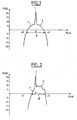
- FIG. 1 represents the classical spectrum of a coded optical signal NRZ and more precisely the optical power P (in dB) according to the frequency f (in arbitrary units).
- This spectrum is characterized by a main band comprising a maximum central peak 1 associated with the carrier wave and two lateral bands symmetrical 2, 3 on either side of this peak 1 relating to coding.
- This main band has a spectral width B of -10 dB about 59 GHz to about 40 Gb / s. Also, spacing at 50 GHz in a 40 GHz system would lead to too much overlap main bands of adjacent channels. This crosstalk increases the transmission error rate unacceptably.
- the two sidebands 2, 3 contain redundant information. Also, in order to increase spectral efficiency, it is known to filter one of them.
- filtering is difficult to implement because involves a precise and delicate adjustment of the filter position.
- the length of the carrier, depending on the laser source will vary during the time and / or depending on the temperature so that a control of the Spectrum filter is needed.
- the filter form must be specific and is complex to obtain.
- PSBT Phase-Shaped Binary Transmission in English
- this format is characterized by phase modulation in the form of slots with level changes centered in the '0's.
- the height and the sign of variations are chosen for example depending on the environment of a '0' that is to say, depending on whether the latter is surrounded by '0', is on the left or right of a group of '1', is isolated between two '1'.
- a variation is generally of the order of ⁇ ⁇ .
- a modulator is used operating in "push-pull” and controlled an electric encoder coupled to a a low-pass electric filter.
- This is typically a modulator interferometric Mach-Zehnder necessarily driven on both arm with opposite control voltages.
- duobinary coded signal is very complicated, in particular the determination of an operating point involves a large number of parameters (bias voltages, peak-to-peak voltage etc) and requires a delicate servoing carried out around the point of non-zero minimum transmission.
- the transmission performance is clearly below a NRZ or RZ encoded signal, particularly in terms of signal-to-noise ratio or sensitivity ie power required at the receiver to obtain a given error rate.
- the object of the invention is to provide a coded optical signal of width spectral reduced, simple to achieve and good quality even at high speed, for example at 40 Gb / s.
- the invention finds particular application for the transmission of coded signals multiplexed in wavelength.
- the invention proposes a method of forming at least one optical signal coded from an intensity modulation of at least one so-called continuous carrier wave by binary data in a non-return to zero or return format.
- the coded signal having a main band of given spectral width, characterized in that , in order to reduce the spectral width, it comprises a phase modulation in the form of positive impulse phase variations and negative impulse phase variations adapted to be substantially synchronized respectively with the rise and fall of the modulated intensity or vice versa.
- the method according to the invention makes it possible to overcome the filtering of bandaged.
- phase modulation according to the invention is original and simpler to implement that modulation for a PSBT format.
- a phase modulator separated from an intensity modulator can be used and disposed upstream or downstream.
- phase modulation according to the invention does not prevent a additional phase modulation of the type 'chirp' as obtained in some cases of intensity modulation schemes, for example when only modulates an electrode of a Mach-Zehnder modulator in LiNb03 "z-cut ".
- the phase variations pulses have, in absolute value, a maximum of between 0.5 and 1.8 radians and preferably substantially equal to 0.75 radians.
- This range of variation guarantees optimal signal quality in term of bandwidth and therefore an optimal quality of the signal in reception when several wavelengths with low frequency spacing are multiplexed.
- a low amplitude phase modulation is sufficient to obtain spectral compression. This allows a gain in energy consumption by a reduction in the level of the control voltage to be applied to the modulator in phase and a decrease in the cost of components.
- Positive and negative impulse phase variations can be preferably substantially symmetrical, for simplicity of Implementation.
- the half-height width of the pulsed phase be greater than or equal to half the transmission period, ie T / 2, to further optimize the spectral compression.
- the shape of the pulsed phase variations can be substantially triangular.
- This form is preferred to a niche type with a maintaining the transitional level of the phase.
- the time difference between the phase variations impulses and ascents or descents may be less than or equal to About 12% in absolute value of the transmission period.
- a plurality of coded signals being formed according to said method defined above, the latter furthermore includes the choice of a frequency separation for the waves carriers less than double the flow rate.
- the method may include filtering after encodings and preferably by a guide array multiplexer or by a interleaving multiplexing.
- This filtering strengthens the quality of the transmission, particularly in acting at crosses between adjacent spectral bands.
- the invention also proposes a coding system for setting of the previously defined method comprising for each carrier wave to be modulated, means for phase modulation and intensity modulation means preferably integrated on the same support.
- the modulation means phase include an electro-optical modulator based on niobate lithium and the intensity modulation means comprise a modulator Mach-Zehnder interferometer, preferably based on niobate lithium.
- Figure 2 shows the spectrum of an NRZ coded optical signal and phase-modulated according to the invention in a first mode of preferred embodiment. More specifically, the spectrum is shown in terms of optical power P (in dB) as a function of frequency f (in units arbitrary).
- This spectrum is characterized by a main band comprising a maximum peak 1 'associated with the carrier wave and two lateral bands asymmetric 2 ', 3' on either side of this peak 1 '.
- This main band has a spectral width B 'at -10 dB reduced compared to the classical spectral width B, and equal to 43 GHz around 40 GHz.
- Interchannel frequency spacing at 50 GHz becomes possible in a 40 GHz transmission system while maintaining the quality of NRZ or RZ signal.
- the compression of the band results from a specific modulation in phase superimposed on classical modulation in intensity for example NRZ.
- FIG. 3 shows the curves C 1 and C 2 respectively representing these modulations of intensity I (expressed in arbitrary units) and of phase ⁇ (expressed in rad) during the time t (expressed in picoseconds).
- Modulation in intensity l is defined according to the following sequence of data binaries: 011110101100100.
- Bit time is 25 ps for the selected 40 GHz coding in this example.
- the phase modulation is in the form of positive impulse phase variations ⁇ 1 and negative ⁇ 2 designed to be substantially synchronized respectively with the rising edges and the falling edges of the modulated intensity.
- the positive and negative pulse phase variations ⁇ 1 , ⁇ 2 are chosen substantially symmetrical for simplicity in the control.
- the pulses ⁇ 1 , ⁇ 2 are set on the fronts.
- a time difference between the impulse phase variations and the rise and fall is less than or equal to approximately 12% in absolute value of the bit time T, ie an offset of ⁇ 3 ps with respect to the edge at 40 Gb / s.
- the pulses ⁇ 1 , ⁇ 2 preferably have a maximum of 0.75 radians.
- a Dirac pulse is insufficient.
- a half-height width l 1 of the impulse phase variations ⁇ 1 , ⁇ 2 is chosen, for example equal to half the bit time.
- the shape of the impulse phase variations ⁇ 1 , ⁇ 2 is substantially triangular.
- the positive impulse phase variations ⁇ 1 and the negative impulse phase variations ⁇ 2 designed to be substantially synchronized respectively with the falling edges and the rising edges.
- the energy is concentrated to lower frequencies (left side band) instead of higher frequencies (right side band).
- FIG. 4 shows an example of a generator 10 of the optical signal NRZ coded and phase modulated whose characteristics are presented in the previous figures 2 and 3.
- the modulator in phase 5 is an electro-optical modulator and has a waveguide structure and based on lithium niobate.
- phase variations shape, width .
- phase modulator based on semiconductors is also possible.
- the carrier wave modulated in phase then propagates in the intensity modulator 7 which is preferably a modulator interferometric Mach-Zehnder type lithium niobate.
- Electrodes E2, E3 arms b1, b2 are respectively controlled from the sequence of data D and its complement D *.
- An electroabsorption modulator (EAM) is also possible.
- the signal coded NRZ and modulated in phase s 1 is obtained.
- phase modulation is performed after the intensity modulation.
- This DWDM 100 transmission system at 40 Gb / s uses a plan allocation with frequency spacing equidistant to 50 GHz.
- the spectrum is shown in terms of optical power P (in dB) in function of the wavelength ⁇ (in arbitrary unit).
- This spectrum has three maximum peaks P1 to P3 to distinct carrier wavelengths ⁇ 1, ⁇ c, ⁇ 2 respectively substantially equal to 1545.72 nm, 1546.12 nm, 1546.52 nm.
- Figures 7 to 9 show three diagrams of the eye, both first being associated with the transmission system of Figure 6 and the last to a simple NRZ transmission system.
- the first diagram of the eye Oe1 presented in FIG. 7 corresponds to that obtained for the central coded signal s 2 when the multiplexer Mux is a filtering component, for example a multiplexer with guide arrays known as AWG and preferably of the same nature as the one chosen. demultiplexing side.
- the multiplexer Mux is a filtering component, for example a multiplexer with guide arrays known as AWG and preferably of the same nature as the one chosen. demultiplexing side.
- the second diagram of the eye Oe2 shown in FIG. 8 corresponds to that obtained for the central coded signal s 2 when the multiplexer Mux is a passive component such as a coupler.
- the third eye diagram Oe3 presented in Figure 9 corresponds to that obtained for a central coded signal presenting only NRZ coding and with a component type multiplexer passive.
- the first diagram of the eye Oe1 presents a large opening and reflects the quality of the received signal despite the phase modulation.
- the second diagram of the eye Oe2 presents an opening acceptable unlike the third diagram of the Oe3 eye.
- the invention applies equally well to a coded signal RZ by providing for necessary means to ensure the synchronization of the modulation of phase with the intensity modulation especially when the pulses are particularly narrow.
- the invention also applies to a number greater than 3 multiplexed signals.
Landscapes
- Physics & Mathematics (AREA)
- Engineering & Computer Science (AREA)
- Computer Networks & Wireless Communication (AREA)
- Signal Processing (AREA)
- Electromagnetism (AREA)
- Optics & Photonics (AREA)
- Spectroscopy & Molecular Physics (AREA)
- Optical Communication System (AREA)
- Dc Digital Transmission (AREA)
- Signal Processing For Digital Recording And Reproducing (AREA)
- Stabilization Of Oscillater, Synchronisation, Frequency Synthesizers (AREA)
Abstract
Description
caractérisée en ce que, afin de réduire la largeur spectrale, elle comprend une modulation de phase sous forme de variations de phase impulsionnelles positives et des variations de phase impulsionnelles négatives aptes à être sensiblement synchronisées respectivement avec les montées et les descentes de l'intensité modulée ou vice-versa.
- la figure 1, déjà décrite, montre le spectre classique d'un signal optique codé NRZ uniquement,
- la figure 2 montre le spectre d'un signal optique codé NRZ et modulé en phase conformément à l'invention dans un premier mode de réalisation préféré;
- la figure 3 montre les modulations en intensité et en phase nécessaires pour l'obtention du spectre de la figure 2,
- la figure 4 montre un exemple de générateur du signal codé NRZ et modulé en phase dont les caractéristiques sont présentées dans les figures 2 et 3,
- la figure 5 montre un système de transmission de trois signaux multiplexés codés NRZ et modulés en phase conformément à l'invention dans un deuxième mode de réalisation de l'invention,
- la figure 6 montre les spectres des trois signaux multiplexés transmis par le système de transmission de la figure 5;
- les figures 7 à 9 montrent trois diagrammes de l'oeil, les deux premiers étant associés au système de transmission de la figure 6 et le dernier à un système de transmission en NRZ simple.
- un laser 4 émettant une onde continue porteuse CW à une longueur d'onde par exemple dans la bande C ou L,
- un modulateur de phase 5 commandé par un précodeur électrique 6 à 40 GHz à partir de la séquence de données D déjà indiquée ci-dessus,
- et un modulateur d'intensité 7.
- un ensemble 20 de trois générateurs 21, 22, 23 similaires au générateur déjà décrit 10,
- un multiplexeur en longueur d'onde Mux,
- une ligne de transmission par fibre optique FO,
- un démultiplexeur en longueur d'onde Demux par exemple un démultiplexeur à réseaux de guides dit AWG,
- un ensemble 20 de trois récepteurs 31, 32, 33.
Claims (10)
- Méthode de formation d'au moins un signal optique codé (s1 à s3) à partir d'une modulation d'intensité d'au moins une onde continue dite porteuse (CW) par des données binaires (D, D*) selon un format non retour à zéro ou retour à zéro, le signal codé (s1) présentant une bande principale de largeur spectrale donnée (B'),
caractérisée en ce que, afin de réduire la largeur spectrale, elle comprend une modulation de phase sous forme de variations de phase impulsionnelles positives (ϕ1) et des variations de phase impulsionnelles négatives (ϕ2) aptes à être sensiblement synchronisées respectivement avec les montées et les descentes de l'intensité modulée (l) ou vice-versa. - Méthode de formation d'au moins un signal codé (s1 à s3) selon la revendication 1 caractérisée en ce que les variations de phase impulsionnelles (ϕ1, ϕ2) présentent, en valeur absolue, un maximum compris entre 0,5 et 1,8 radians.
- Méthode de formation d'au moins un signal codé (s1 à s3) selon l'une des revendications 1 ou 2 caractérisée en ce que les variations de phase impulsionnelles négatives et positives (ϕ1, ϕ2) sont sensiblement symétriques.
- Méthode de formation d'au moins un signal codé (s1 à s3) selon l'une des revendications 1 à 3 caractérisée en ce que la largeur à mi-hauteur (l1) des variations de phase impulsionnelles (ϕ1, ϕ2) est supérieure ou égale à la moitié de la période de transmission (T).
- Méthode de formation d'au moins un signal codé (s1 à s3) selon l'une des revendications 1 à 4 caractérisée en ce que la forme des variations de phase impulsionnelles (ϕ1, ϕ2) est sensiblement triangulaire.
- Méthode de formation d'au moins un signal codé (s1 à s3) selon l'une des revendications 1 à 5 caractérisée en ce que le décalage temporel entre les variations de phase impulsionnelles (ϕ1, ϕ2) et les montées ou les descentes est inférieur ou égal à 12% environ en valeur absolue de la période de transmission (T).
- Méthode de formation d'au moins un signal codé (s1 à s3) selon l'une des revendications 1 à 6 caractérisée en ce que, lorsqu'une pluralité de signaux codés sont formés suivant ladite méthode, elle comprend le choix d'un espacement fréquentiel pour les ondes porteuses inférieur au double du débit.
- Méthode de formation d'au moins un signal codé (s1 à s3) selon l'une des revendications 1 à 7 caractérisée en ce que, lorsqu'une pluralité de signaux codés sont formés suivant ladite méthode, elle comprend un filtrage après les codages par un multiplexeur à réseaux de guides ou par un multiplexage par entrelacement.
- Système de codage (10, 20, 21 à 23) pour la mise en oeuvre de la méthode définie selon l'une des revendications 1 à 8 comportant pour chaque onde porteuse (CW) à moduler, des moyens de modulation de phase (5) et des moyens de modulation d'intensité (7).
- Système de codage (10, 20, 21 à 23) selon la, revendication 9 caractérisé en ce que les moyens de modulation en phase (5) comprennent un modulateur électro-optique à base de niobate de lithium et en ce que les moyens de modulation en intensité (7) comprennent un modulateur interférométrique de type Mach-Zehnder.
Applications Claiming Priority (2)
| Application Number | Priority Date | Filing Date | Title |
|---|---|---|---|
| FR0309997A FR2859056B1 (fr) | 2003-08-19 | 2003-08-19 | Methode de formation d'un signal optique code suivant un format retour a zero ou non retour a zero |
| FR0309997 | 2003-08-19 |
Publications (2)
| Publication Number | Publication Date |
|---|---|
| EP1508984A1 true EP1508984A1 (fr) | 2005-02-23 |
| EP1508984B1 EP1508984B1 (fr) | 2006-08-30 |
Family
ID=34043779
Family Applications (1)
| Application Number | Title | Priority Date | Filing Date |
|---|---|---|---|
| EP04291702A Expired - Lifetime EP1508984B1 (fr) | 2003-08-19 | 2004-07-05 | Method de formation d'un signal optique code suivant un format retour a zero ou non retour a zero |
Country Status (5)
| Country | Link |
|---|---|
| US (1) | US20050041983A1 (fr) |
| EP (1) | EP1508984B1 (fr) |
| AT (1) | ATE338392T1 (fr) |
| DE (1) | DE602004002160T2 (fr) |
| FR (1) | FR2859056B1 (fr) |
Families Citing this family (4)
| Publication number | Priority date | Publication date | Assignee | Title |
|---|---|---|---|---|
| WO2006029402A2 (fr) * | 2004-09-10 | 2006-03-16 | Magiq Technologies, Inc. | Procede et appareil destines a produire des impulsions optiques pour une qkd |
| US8055137B2 (en) * | 2007-03-27 | 2011-11-08 | Tongqing Wang | Phase coded non-return-to-zero optical transmitter |
| EP2153204A4 (fr) * | 2007-06-07 | 2016-06-15 | Afl Telecommunications Llc | Procédé de détection de fibres optiques et de rubans de fibres optiques |
| US11047766B2 (en) | 2018-04-11 | 2021-06-29 | Afl Telecommunications Llc | Systems and methods for identification and testing of optical fibers |
Citations (3)
| Publication number | Priority date | Publication date | Assignee | Title |
|---|---|---|---|---|
| FR2670638A1 (fr) * | 1990-12-17 | 1992-06-19 | Alcatel Nv | Procede et systeme de transmission optique a saut de phase. |
| US5920416A (en) * | 1996-02-23 | 1999-07-06 | Cit Alcatel | Optical method of transmitting digital data |
| US20030123771A1 (en) * | 2001-11-11 | 2003-07-03 | Yue Liu | Optical signal modulation method and optical signal transmission system for high speed transmission system |
Family Cites Families (10)
| Publication number | Priority date | Publication date | Assignee | Title |
|---|---|---|---|---|
| FR2685834B1 (fr) * | 1991-12-31 | 1995-03-31 | France Telecom | Systeme de transmission numerique longue distance sur fibre optique a compensation a l'emission des distorsions. |
| IT1279248B1 (it) * | 1995-12-21 | 1997-12-09 | Pirelli Cavi S P A Ora Pirelli | Sistema di trasmissione di segnali ottici modulati e depolarizzati |
| US20040161245A1 (en) * | 1996-12-20 | 2004-08-19 | Bergano Neal S. | Synchronous amplitude modulation for improved performance of optical transmission systems |
| JP3337980B2 (ja) * | 1998-06-29 | 2002-10-28 | 沖電気工業株式会社 | 光送信器及び光伝送システム |
| FR2781322B1 (fr) * | 1998-07-20 | 2000-09-08 | Alsthom Cge Alcatel | Dispositif d'emission de donnees optiques |
| DE60020241T2 (de) * | 2000-11-06 | 2005-11-24 | Alcatel | Optische Modulationsart für NRZ-Signale und optischer Sender |
| US6741763B1 (en) * | 2001-01-17 | 2004-05-25 | The Texas A & M University | Optical data transmission apparatus and method |
| ITRM20020056A1 (it) * | 2002-02-04 | 2003-08-04 | Mario Zitelli | Modulazione combinata di intensita' e fase in un sistema di comunicazione ottico. |
| JP2003244102A (ja) * | 2002-02-20 | 2003-08-29 | Hitachi Ltd | 光帯域狭窄化送信装置および光残留サイドバンド送信装置 |
| US7027669B2 (en) * | 2003-08-15 | 2006-04-11 | Lucent Technologies Inc. | Methods and apparatus for optical pulse generator with progressive phase shift |
-
2003
- 2003-08-19 FR FR0309997A patent/FR2859056B1/fr not_active Expired - Fee Related
-
2004
- 2004-07-05 EP EP04291702A patent/EP1508984B1/fr not_active Expired - Lifetime
- 2004-07-05 DE DE602004002160T patent/DE602004002160T2/de not_active Expired - Lifetime
- 2004-07-05 AT AT04291702T patent/ATE338392T1/de not_active IP Right Cessation
- 2004-07-14 US US10/890,120 patent/US20050041983A1/en not_active Abandoned
Patent Citations (3)
| Publication number | Priority date | Publication date | Assignee | Title |
|---|---|---|---|---|
| FR2670638A1 (fr) * | 1990-12-17 | 1992-06-19 | Alcatel Nv | Procede et systeme de transmission optique a saut de phase. |
| US5920416A (en) * | 1996-02-23 | 1999-07-06 | Cit Alcatel | Optical method of transmitting digital data |
| US20030123771A1 (en) * | 2001-11-11 | 2003-07-03 | Yue Liu | Optical signal modulation method and optical signal transmission system for high speed transmission system |
Also Published As
| Publication number | Publication date |
|---|---|
| DE602004002160D1 (de) | 2006-10-12 |
| FR2859056B1 (fr) | 2005-09-30 |
| EP1508984B1 (fr) | 2006-08-30 |
| US20050041983A1 (en) | 2005-02-24 |
| FR2859056A1 (fr) | 2005-02-25 |
| ATE338392T1 (de) | 2006-09-15 |
| DE602004002160T2 (de) | 2007-07-19 |
Similar Documents
| Publication | Publication Date | Title |
|---|---|---|
| EP0792036B1 (fr) | Procédé de transmission optique de données numériques | |
| FR2761490A1 (fr) | Circuit de detection de positions d'impulsions optiques, appareil de production d'impulsions optiques et procedes pour leur utilisation | |
| FR2724510A1 (fr) | Systeme de transmission optique | |
| EP3032325B1 (fr) | Dispositif de modulation d'amplitude d'un signal optique | |
| FR2732123A1 (fr) | Procede de modulation d'impulsions optiques avec compression et systeme de modulation pour la mise en oeuvre de ce procede | |
| FR2756440A1 (fr) | Dispositif d'emission de donnees optiques | |
| EP0716486B1 (fr) | Dispositif convertisseur de longueur d'onde | |
| WO2007074297A1 (fr) | Transmission optique entre un terminal central et une pluralite de terminaux clients via un reseau optique | |
| EP1617576B1 (fr) | Format de modulation FSK à largeur de bande limitée | |
| FR2762732A1 (fr) | Procede et dispositif de decompression d'impulsions constituant un signal optique binaire | |
| EP1508984B1 (fr) | Method de formation d'un signal optique code suivant un format retour a zero ou non retour a zero | |
| FR2734677A1 (fr) | Procede d'inscription de donnees binaires sur une onde porteuse, notamment optique, et systeme de transmission utilisant ce procede | |
| EP0618698A1 (fr) | Dispositif optique de récupération du rythme d'un signal codé | |
| KR100480274B1 (ko) | 광위상변조기를 이용한 광전송시스템 | |
| FR2950746A1 (fr) | Modulateur avec marquage de polarisation | |
| FR2787593A1 (fr) | Modulateur de type mach-zehnder presentant un taux d'extinction tres eleve | |
| FR2832570A1 (fr) | Procede et appareil de transmission d'un signal optique par brouillage de polarisation | |
| EP1134859B1 (fr) | Dispositif d'amplification optique | |
| EP1497939A1 (fr) | Dispositif optique et procede pour convertir des signaux wdm en un signal otdm et reciproquement | |
| EP1398896A1 (fr) | Peigne de fréquences pour réseau à multiplexage par répartition de fréquences optiques | |
| EP1311079B1 (fr) | Système de transmission de signal optique à phase contrôlée | |
| Ji et al. | Passband optimisation for hybrid 40G/100G system using tunable asymmetric interleaver | |
| WO2002019574A1 (fr) | Regenerateur tout-optique pour signaux multiplexes en longueur d'onde | |
| EP1777904B1 (fr) | Multiplexeur à haut débit à architecture parallèle | |
| EP1142168A1 (fr) | Dispositif de generation de porteuses pour systeme de transmission optique a multiplexage en longueur d'onde a signaux rz |
Legal Events
| Date | Code | Title | Description |
|---|---|---|---|
| PUAI | Public reference made under article 153(3) epc to a published international application that has entered the european phase |
Free format text: ORIGINAL CODE: 0009012 |
|
| AK | Designated contracting states |
Kind code of ref document: A1 Designated state(s): AT BE BG CH CY CZ DE DK EE ES FI FR GB GR HU IE IT LI LU MC NL PL PT RO SE SI SK TR |
|
| AX | Request for extension of the european patent |
Extension state: AL HR LT LV MK |
|
| 17P | Request for examination filed |
Effective date: 20050823 |
|
| AKX | Designation fees paid |
Designated state(s): AT BE BG CH CY CZ DE DK EE ES FI FR GB GR HU IE IT LI LU MC NL PL PT RO SE SI SK TR |
|
| GRAP | Despatch of communication of intention to grant a patent |
Free format text: ORIGINAL CODE: EPIDOSNIGR1 |
|
| GRAS | Grant fee paid |
Free format text: ORIGINAL CODE: EPIDOSNIGR3 |
|
| GRAA | (expected) grant |
Free format text: ORIGINAL CODE: 0009210 |
|
| AK | Designated contracting states |
Kind code of ref document: B1 Designated state(s): AT BE BG CH CY CZ DE DK EE ES FI FR GB GR HU IE IT LI LU MC NL PL PT RO SE SI SK TR |
|
| PG25 | Lapsed in a contracting state [announced via postgrant information from national office to epo] |
Ref country code: IT Free format text: LAPSE BECAUSE OF FAILURE TO SUBMIT A TRANSLATION OF THE DESCRIPTION OR TO PAY THE FEE WITHIN THE PRESCRIBED TIME-LIMIT;WARNING: LAPSES OF ITALIAN PATENTS WITH EFFECTIVE DATE BEFORE 2007 MAY HAVE OCCURRED AT ANY TIME BEFORE 2007. THE CORRECT EFFECTIVE DATE MAY BE DIFFERENT FROM THE ONE RECORDED. Effective date: 20060830 Ref country code: FI Free format text: LAPSE BECAUSE OF FAILURE TO SUBMIT A TRANSLATION OF THE DESCRIPTION OR TO PAY THE FEE WITHIN THE PRESCRIBED TIME-LIMIT Effective date: 20060830 Ref country code: SK Free format text: LAPSE BECAUSE OF FAILURE TO SUBMIT A TRANSLATION OF THE DESCRIPTION OR TO PAY THE FEE WITHIN THE PRESCRIBED TIME-LIMIT Effective date: 20060830 Ref country code: PL Free format text: LAPSE BECAUSE OF FAILURE TO SUBMIT A TRANSLATION OF THE DESCRIPTION OR TO PAY THE FEE WITHIN THE PRESCRIBED TIME-LIMIT Effective date: 20060830 Ref country code: CZ Free format text: LAPSE BECAUSE OF FAILURE TO SUBMIT A TRANSLATION OF THE DESCRIPTION OR TO PAY THE FEE WITHIN THE PRESCRIBED TIME-LIMIT Effective date: 20060830 Ref country code: NL Free format text: LAPSE BECAUSE OF FAILURE TO SUBMIT A TRANSLATION OF THE DESCRIPTION OR TO PAY THE FEE WITHIN THE PRESCRIBED TIME-LIMIT Effective date: 20060830 Ref country code: IE Free format text: LAPSE BECAUSE OF FAILURE TO SUBMIT A TRANSLATION OF THE DESCRIPTION OR TO PAY THE FEE WITHIN THE PRESCRIBED TIME-LIMIT Effective date: 20060830 Ref country code: SI Free format text: LAPSE BECAUSE OF FAILURE TO SUBMIT A TRANSLATION OF THE DESCRIPTION OR TO PAY THE FEE WITHIN THE PRESCRIBED TIME-LIMIT Effective date: 20060830 Ref country code: RO Free format text: LAPSE BECAUSE OF FAILURE TO SUBMIT A TRANSLATION OF THE DESCRIPTION OR TO PAY THE FEE WITHIN THE PRESCRIBED TIME-LIMIT Effective date: 20060830 Ref country code: AT Free format text: LAPSE BECAUSE OF FAILURE TO SUBMIT A TRANSLATION OF THE DESCRIPTION OR TO PAY THE FEE WITHIN THE PRESCRIBED TIME-LIMIT Effective date: 20060830 |
|
| REG | Reference to a national code |
Ref country code: GB Ref legal event code: FG4D Free format text: NOT ENGLISH |
|
| REG | Reference to a national code |
Ref country code: CH Ref legal event code: EP |
|
| REG | Reference to a national code |
Ref country code: IE Ref legal event code: FG4D Free format text: LANGUAGE OF EP DOCUMENT: FRENCH |
|
| REF | Corresponds to: |
Ref document number: 602004002160 Country of ref document: DE Date of ref document: 20061012 Kind code of ref document: P |
|
| GBT | Gb: translation of ep patent filed (gb section 77(6)(a)/1977) |
Effective date: 20061106 |
|
| PG25 | Lapsed in a contracting state [announced via postgrant information from national office to epo] |
Ref country code: SE Free format text: LAPSE BECAUSE OF FAILURE TO SUBMIT A TRANSLATION OF THE DESCRIPTION OR TO PAY THE FEE WITHIN THE PRESCRIBED TIME-LIMIT Effective date: 20061130 Ref country code: DK Free format text: LAPSE BECAUSE OF FAILURE TO SUBMIT A TRANSLATION OF THE DESCRIPTION OR TO PAY THE FEE WITHIN THE PRESCRIBED TIME-LIMIT Effective date: 20061130 Ref country code: BG Free format text: LAPSE BECAUSE OF FAILURE TO SUBMIT A TRANSLATION OF THE DESCRIPTION OR TO PAY THE FEE WITHIN THE PRESCRIBED TIME-LIMIT Effective date: 20061130 |
|
| PG25 | Lapsed in a contracting state [announced via postgrant information from national office to epo] |
Ref country code: ES Free format text: LAPSE BECAUSE OF FAILURE TO SUBMIT A TRANSLATION OF THE DESCRIPTION OR TO PAY THE FEE WITHIN THE PRESCRIBED TIME-LIMIT Effective date: 20061211 |
|
| PG25 | Lapsed in a contracting state [announced via postgrant information from national office to epo] |
Ref country code: PT Free format text: LAPSE BECAUSE OF FAILURE TO SUBMIT A TRANSLATION OF THE DESCRIPTION OR TO PAY THE FEE WITHIN THE PRESCRIBED TIME-LIMIT Effective date: 20070206 |
|
| NLV1 | Nl: lapsed or annulled due to failure to fulfill the requirements of art. 29p and 29m of the patents act | ||
| RAP2 | Party data changed (patent owner data changed or rights of a patent transferred) |
Owner name: ALCATEL LUCENT |
|
| REG | Reference to a national code |
Ref country code: IE Ref legal event code: FD4D |
|
| PLBE | No opposition filed within time limit |
Free format text: ORIGINAL CODE: 0009261 |
|
| STAA | Information on the status of an ep patent application or granted ep patent |
Free format text: STATUS: NO OPPOSITION FILED WITHIN TIME LIMIT |
|
| REG | Reference to a national code |
Ref country code: FR Ref legal event code: CD |
|
| 26N | No opposition filed |
Effective date: 20070531 |
|
| BERE | Be: lapsed |
Owner name: ALCATEL Effective date: 20070731 |
|
| PG25 | Lapsed in a contracting state [announced via postgrant information from national office to epo] |
Ref country code: GR Free format text: LAPSE BECAUSE OF FAILURE TO SUBMIT A TRANSLATION OF THE DESCRIPTION OR TO PAY THE FEE WITHIN THE PRESCRIBED TIME-LIMIT Effective date: 20061201 Ref country code: MC Free format text: LAPSE BECAUSE OF NON-PAYMENT OF DUE FEES Effective date: 20070731 |
|
| PG25 | Lapsed in a contracting state [announced via postgrant information from national office to epo] |
Ref country code: EE Free format text: LAPSE BECAUSE OF FAILURE TO SUBMIT A TRANSLATION OF THE DESCRIPTION OR TO PAY THE FEE WITHIN THE PRESCRIBED TIME-LIMIT Effective date: 20060830 |
|
| PG25 | Lapsed in a contracting state [announced via postgrant information from national office to epo] |
Ref country code: BE Free format text: LAPSE BECAUSE OF NON-PAYMENT OF DUE FEES Effective date: 20070731 |
|
| PGRI | Patent reinstated in contracting state [announced from national office to epo] |
Ref country code: IT Effective date: 20081001 |
|
| REG | Reference to a national code |
Ref country code: CH Ref legal event code: PL |
|
| PG25 | Lapsed in a contracting state [announced via postgrant information from national office to epo] |
Ref country code: LI Free format text: LAPSE BECAUSE OF NON-PAYMENT OF DUE FEES Effective date: 20080731 Ref country code: CH Free format text: LAPSE BECAUSE OF NON-PAYMENT OF DUE FEES Effective date: 20080731 |
|
| PG25 | Lapsed in a contracting state [announced via postgrant information from national office to epo] |
Ref country code: CY Free format text: LAPSE BECAUSE OF FAILURE TO SUBMIT A TRANSLATION OF THE DESCRIPTION OR TO PAY THE FEE WITHIN THE PRESCRIBED TIME-LIMIT Effective date: 20060830 Ref country code: LU Free format text: LAPSE BECAUSE OF NON-PAYMENT OF DUE FEES Effective date: 20070705 |
|
| PG25 | Lapsed in a contracting state [announced via postgrant information from national office to epo] |
Ref country code: HU Free format text: LAPSE BECAUSE OF FAILURE TO SUBMIT A TRANSLATION OF THE DESCRIPTION OR TO PAY THE FEE WITHIN THE PRESCRIBED TIME-LIMIT Effective date: 20070301 Ref country code: TR Free format text: LAPSE BECAUSE OF FAILURE TO SUBMIT A TRANSLATION OF THE DESCRIPTION OR TO PAY THE FEE WITHIN THE PRESCRIBED TIME-LIMIT Effective date: 20060830 |
|
| PGFP | Annual fee paid to national office [announced via postgrant information from national office to epo] |
Ref country code: IT Payment date: 20100722 Year of fee payment: 7 |
|
| PG25 | Lapsed in a contracting state [announced via postgrant information from national office to epo] |
Ref country code: IT Free format text: LAPSE BECAUSE OF FAILURE TO SUBMIT A TRANSLATION OF THE DESCRIPTION OR TO PAY THE FEE WITHIN THE PRESCRIBED TIME-LIMIT Effective date: 20110705 |
|
| REG | Reference to a national code |
Ref country code: FR Ref legal event code: GC Effective date: 20140717 |
|
| REG | Reference to a national code |
Ref country code: FR Ref legal event code: RG Effective date: 20141016 |
|
| REG | Reference to a national code |
Ref country code: FR Ref legal event code: PLFP Year of fee payment: 12 |
|
| REG | Reference to a national code |
Ref country code: FR Ref legal event code: CA Effective date: 20150521 |
|
| REG | Reference to a national code |
Ref country code: FR Ref legal event code: CA Effective date: 20150521 |
|
| PGFP | Annual fee paid to national office [announced via postgrant information from national office to epo] |
Ref country code: FR Payment date: 20150626 Year of fee payment: 12 |
|
| PGFP | Annual fee paid to national office [announced via postgrant information from national office to epo] |
Ref country code: DE Payment date: 20150721 Year of fee payment: 12 Ref country code: GB Payment date: 20150721 Year of fee payment: 12 |
|
| REG | Reference to a national code |
Ref country code: DE Ref legal event code: R119 Ref document number: 602004002160 Country of ref document: DE |
|
| GBPC | Gb: european patent ceased through non-payment of renewal fee |
Effective date: 20160705 |
|
| PG25 | Lapsed in a contracting state [announced via postgrant information from national office to epo] |
Ref country code: FR Free format text: LAPSE BECAUSE OF NON-PAYMENT OF DUE FEES Effective date: 20160801 Ref country code: DE Free format text: LAPSE BECAUSE OF NON-PAYMENT OF DUE FEES Effective date: 20170201 |
|
| REG | Reference to a national code |
Ref country code: FR Ref legal event code: ST Effective date: 20170331 |
|
| PG25 | Lapsed in a contracting state [announced via postgrant information from national office to epo] |
Ref country code: GB Free format text: LAPSE BECAUSE OF NON-PAYMENT OF DUE FEES Effective date: 20160705 |