EP1508682A2 - Apparatus and method for accelerated exhaust system component heating - Google Patents
Apparatus and method for accelerated exhaust system component heating Download PDFInfo
- Publication number
- EP1508682A2 EP1508682A2 EP04016273A EP04016273A EP1508682A2 EP 1508682 A2 EP1508682 A2 EP 1508682A2 EP 04016273 A EP04016273 A EP 04016273A EP 04016273 A EP04016273 A EP 04016273A EP 1508682 A2 EP1508682 A2 EP 1508682A2
- Authority
- EP
- European Patent Office
- Prior art keywords
- engine
- generator
- load
- electrical load
- exhaust system
- Prior art date
- Legal status (The legal status is an assumption and is not a legal conclusion. Google has not performed a legal analysis and makes no representation as to the accuracy of the status listed.)
- Granted
Links
Images


Classifications
-
- F—MECHANICAL ENGINEERING; LIGHTING; HEATING; WEAPONS; BLASTING
- F02—COMBUSTION ENGINES; HOT-GAS OR COMBUSTION-PRODUCT ENGINE PLANTS
- F02D—CONTROLLING COMBUSTION ENGINES
- F02D41/00—Electrical control of supply of combustible mixture or its constituents
- F02D41/02—Circuit arrangements for generating control signals
- F02D41/021—Introducing corrections for particular conditions exterior to the engine
- F02D41/0235—Introducing corrections for particular conditions exterior to the engine in relation with the state of the exhaust gas treating apparatus
- F02D41/024—Introducing corrections for particular conditions exterior to the engine in relation with the state of the exhaust gas treating apparatus to increase temperature of the exhaust gas treating apparatus
- F02D41/0245—Introducing corrections for particular conditions exterior to the engine in relation with the state of the exhaust gas treating apparatus to increase temperature of the exhaust gas treating apparatus by increasing temperature of the exhaust gas leaving the engine
-
- F—MECHANICAL ENGINEERING; LIGHTING; HEATING; WEAPONS; BLASTING
- F01—MACHINES OR ENGINES IN GENERAL; ENGINE PLANTS IN GENERAL; STEAM ENGINES
- F01N—GAS-FLOW SILENCERS OR EXHAUST APPARATUS FOR MACHINES OR ENGINES IN GENERAL; GAS-FLOW SILENCERS OR EXHAUST APPARATUS FOR INTERNAL-COMBUSTION ENGINES
- F01N3/00—Exhaust or silencing apparatus having means for purifying, rendering innocuous, or otherwise treating exhaust
- F01N3/08—Exhaust or silencing apparatus having means for purifying, rendering innocuous, or otherwise treating exhaust for rendering innocuous
- F01N3/10—Exhaust or silencing apparatus having means for purifying, rendering innocuous, or otherwise treating exhaust for rendering innocuous by thermal or catalytic conversion of noxious components of exhaust
- F01N3/18—Exhaust or silencing apparatus having means for purifying, rendering innocuous, or otherwise treating exhaust for rendering innocuous by thermal or catalytic conversion of noxious components of exhaust characterised by methods of operation; Control
- F01N3/20—Exhaust or silencing apparatus having means for purifying, rendering innocuous, or otherwise treating exhaust for rendering innocuous by thermal or catalytic conversion of noxious components of exhaust characterised by methods of operation; Control specially adapted for catalytic conversion
- F01N3/2006—Periodically heating or cooling catalytic reactors, e.g. at cold starting or overheating
-
- F—MECHANICAL ENGINEERING; LIGHTING; HEATING; WEAPONS; BLASTING
- F02—COMBUSTION ENGINES; HOT-GAS OR COMBUSTION-PRODUCT ENGINE PLANTS
- F02D—CONTROLLING COMBUSTION ENGINES
- F02D41/00—Electrical control of supply of combustible mixture or its constituents
- F02D41/02—Circuit arrangements for generating control signals
- F02D41/021—Introducing corrections for particular conditions exterior to the engine
- F02D41/0235—Introducing corrections for particular conditions exterior to the engine in relation with the state of the exhaust gas treating apparatus
- F02D41/024—Introducing corrections for particular conditions exterior to the engine in relation with the state of the exhaust gas treating apparatus to increase temperature of the exhaust gas treating apparatus
- F02D2041/026—Introducing corrections for particular conditions exterior to the engine in relation with the state of the exhaust gas treating apparatus to increase temperature of the exhaust gas treating apparatus using an external load, e.g. by increasing generator load or by changing the gear ratio
-
- F—MECHANICAL ENGINEERING; LIGHTING; HEATING; WEAPONS; BLASTING
- F02—COMBUSTION ENGINES; HOT-GAS OR COMBUSTION-PRODUCT ENGINE PLANTS
- F02D—CONTROLLING COMBUSTION ENGINES
- F02D37/00—Non-electrical conjoint control of two or more functions of engines, not otherwise provided for
- F02D37/02—Non-electrical conjoint control of two or more functions of engines, not otherwise provided for one of the functions being ignition
-
- Y—GENERAL TAGGING OF NEW TECHNOLOGICAL DEVELOPMENTS; GENERAL TAGGING OF CROSS-SECTIONAL TECHNOLOGIES SPANNING OVER SEVERAL SECTIONS OF THE IPC; TECHNICAL SUBJECTS COVERED BY FORMER USPC CROSS-REFERENCE ART COLLECTIONS [XRACs] AND DIGESTS
- Y02—TECHNOLOGIES OR APPLICATIONS FOR MITIGATION OR ADAPTATION AGAINST CLIMATE CHANGE
- Y02A—TECHNOLOGIES FOR ADAPTATION TO CLIMATE CHANGE
- Y02A50/00—TECHNOLOGIES FOR ADAPTATION TO CLIMATE CHANGE in human health protection, e.g. against extreme weather
- Y02A50/20—Air quality improvement or preservation, e.g. vehicle emission control or emission reduction by using catalytic converters
-
- Y—GENERAL TAGGING OF NEW TECHNOLOGICAL DEVELOPMENTS; GENERAL TAGGING OF CROSS-SECTIONAL TECHNOLOGIES SPANNING OVER SEVERAL SECTIONS OF THE IPC; TECHNICAL SUBJECTS COVERED BY FORMER USPC CROSS-REFERENCE ART COLLECTIONS [XRACs] AND DIGESTS
- Y02—TECHNOLOGIES OR APPLICATIONS FOR MITIGATION OR ADAPTATION AGAINST CLIMATE CHANGE
- Y02T—CLIMATE CHANGE MITIGATION TECHNOLOGIES RELATED TO TRANSPORTATION
- Y02T10/00—Road transport of goods or passengers
- Y02T10/10—Internal combustion engine [ICE] based vehicles
- Y02T10/12—Improving ICE efficiencies
Definitions
- the present invention is related to managing cold start emissions from automobiles. More particularly, the invention facilitates a reduction in the time it takes for the exhaust system components to warm-up during cold starts.
- Electrically heated catalysts have also been proposed as a means for accelerating the heating of the catalyst. Such systems demand significant electrical energy to effect rapid heating. Energizing electrically heated catalysts for direct heating thereof has been proposed by disconnection of normal vehicle electrical loads from the generator and generator operation in an unregulated mode to rapidly power such a catalyst heater.
- an apparatus for accelerating the heating of exhaust system components during cold start conditions in an automobile includes an engine controller effective to control engine speed by adjusting the engine load operating point.
- a generator driven by the internal combustion engine provides a regulated output.
- the controller is adapted for determining when accelerated heating of the exhaust system components is required and is effective to electrically couple a supplemental electrical load to the generator when accelerated heating of exhaust system components is required.
- a method for accelerated heating of exhaust system components in an automobile includes an internal combustion engine, an engine controller and an electric generator drivingly coupled to the engine and having an electrical output.
- a supplemental electrical load is provided to the generator output to provide a torque load to the engine while engine speed is controlled to a predetermined engine speed profile.
- Engine speed may be controlled, for example, by making fueling adjustments or by making adjustments to the supplemental electrical load.
- FIG. 1 is a schematic illustration of a vehicle powertrain and electrical system in accordance with one embodiment of the present invention
- Figure 2 is a graphic illustration of the general temperature response of a vehicle exhaust system to increased loads at various loads for various degrees of spark retard;
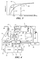
- FIG. 4 is a schematic illustration of a vehicle powertrain and electrical system in accordance with another embodiment of the present invention.
- Figure 5 is a flow chart representing various steps for implementation by one or more electronic controllers in carrying out the present invention.
- Figure 6 is a graphic illustration of an alternate control methodology in accordance with the present invention.
- a motor vehicle includes a powertrain generally labeled 10 and more specifically comprising an internal combustion engine 11 coupled to a multi-ratio automatic transmission 15 through an engaged torque converter clutch 13.
- Transmission 15 has an output shaft 17 which in turn is mechanically coupled to at least one drive wheel through differential and final drive gear sets (not shown).
- Engine 11 also has an accessory drive shaft 19 for driving a plurality of engine driven accessories by way of a pulley and belt system (not shown).
- engine powered accessories may include, for example, air conditioning compressors, intake air superchargers and vehicle electrical system generators.
- PCM 21 includes a microprocessor, read only memory ROM, random access memory RAM, electrically programmable read only memory EPROM, high speed clock, analog to digital (A/D) and digital to analog (D/A) circuitry, and input/output circuitry and devices (I/O) and appropriate signal conditioning and buffer circuitry.
- PCM 21 functions to acquire data from a variety of sensors and control a variety of actuators, respectively, of the powertrain system. Therefore, PCM 21 is shown generally in bi-directional interface with engine 11 and transmission 15 via lines 23 and 27. Also shown is TCC actuator line 25 which commands the torque converter clutch engaged or disengaged.
- PCM 21 also provides an electronic spark timing (EST) signal output on line 29 to ignition controller 31.
- Ignition controller 31 responds to EST signal to provide timed output of drive signals to spark plugs 33 for combusting the fuel charge in the cylinders.
- EST signal may be adapted to provide spark timing signals over a wide range of timing.
- the regulator When the actual output voltage of the alternator is below the desired set-point, the regulator energizes the field winding with a semiconductor switch (not shown) that is connected in series with the field winding 27 of the alternator 25.
- the semiconductor switch is operated at a predetermined pulse width which is increased when the actual output voltage is below the set-point and decreased when the actual output voltage is above the set-point.
- Supplemental electrical load 44 is an electrical load invoked in accordance with the control of the present invention and in addition to the nominal electrical load.
- the supplemental electrical load is activated and controlled such that the net vehicle electrical load is at a predetermined point such as the maximum alternator output operating point as explained further at a later point herein.
- the total load current that is to say the net current provided by the stator winding is labeled I L in the figure and comprises the nominal electrical loads and the supplemental electrical loads.
- supplemental electrical load may be substantial (i.e. on the order of several hundred watts to 1 kilowatt and more), heat transfer may be critical, particularly with a supplemental load that is compact and thus has a relatively high energy dissipation density.
- preferred placements for the supplemental electrical load to transfer the heat most efficiently include heat transfer communication with the engine block, coolant, fuel supply and intake air.
- supplemental electrical load may take the form of an engine block heater, an engine coolant heater, an engine intake air heater or an engine fuel heater.
- Other electrical loads such as exhaust sensor heaters and body electrical loads including electrically heated mirrors and backglass are also contemplated by the present invention.
- Preexisting vehicle electrical loads utilized as supplemental electrical loads may be controlled by parallel redundant circuitry to the normal control circuitry or by adapting the normal control circuitry for such loads.
- Figure 4 illustrates an alternative embodiment of the present invention that may be a more desirable implementation wherein preexisting vehicle electrical loads may be utilized as the supplemental load 44.
- Figure 4 illustrates many of the same features as Figure 1 with the same reference numerals that are used between the two figures corresponding to the same features. Repetition of the same features is not made herein; however, certain differences are described as follows.
- Preexisting vehicle electrical loads particularly high power consuming body electrical loads such as glass defrosters (including electrically heated mirrors and backglass), are commonly controlled by a body control module (BCM) or other control unit apart from the PCM.
- BCM 26 is shown in two-way communication with PCM through a serial bus 28 or alternative means.
- BCM 26 is responsive to operator requests, such as from momentary switch inputs, to control such loads into and out of the circuit. Load switching may be accomplished by way of relays controlled by BCM outputs or directly through power transistors or drivers within the BCM. Line 30 from the BCM represents the control line for supplemental electrical load 44.
- the PCM communicates requests for supplemental electrical loads via bus 28 and the BCM responds by switching supplemental electrical loads into the circuit. Additionally, even high voltage loads that are energized at regulated or unregulated levels higher than the system voltages may provide supplemental electrical loading in accordance with the present invention provided that the regulation of normal electrical loads is maintained.
- One such vehicle system adaptable for such use is disclosed in USPN 4,780,619, the contents of which are incorporated herein by reference.
- FIG. 75 Three curves labeled 75, 76 and 77 are shown plotted against a pair of axes. The curves represent various times in seconds that a particular portion of a vehicle exhaust system takes to reach a target temperature T from a cold start ambient temperature condition and at various engine loads.
- the ambient temperature is substantially 25 degrees C and the target temperature T is substantially 350 degrees C.
- Engine load is represented across the horizontal axis where manifold absolute pressure (MAP) is displayed, it being understood that MAP is a generally accepted indicator of engine load under stoichiometric engine operation for a particular engine operating at a given spark timing.
- MAP manifold absolute pressure
- a typical power output capacity curve of a vehicle alternator is shown therein and labeled 100.
- the power output capacity is higher at higher rotational speeds.
- Output is relatively low at low engine speeds such as 750 RPM and substantially higher at higher engine speeds such as 1500 RPM.
- the power consumed by the nominal electrical load is represented by region 113.
- the additional capacity 115, or any portion thereof, may be provided to the supplemental electrical load.
- the nominal electrical load may consume substantially all of the alternators output capacity 121.
- additional loads vis-à-vis electrical loading of the generator would typically require engine operation at the higher RPM. Such operation may be objectionable to the operator since such high engine speed may seem to be excessive.
- step 502 represents engine speed control wherein engine speed is controlled to a predetermined profile, including a constant speed.
- a cold start engine speed will generally be higher than a warm start engine speed. This allows a greater thermal contribution to the exhaust system facilitated by the more frequent fuel charge burning.
- a benefit of the present invention is that excessive engine speeds, which might be objectionable to the vehicle operator, may be avoidable through the present invention also. Implementation will be a balance between these competing criteria.
- the engine speed control adjusts the engine load operating point to meet the load presented to it and maintain the desired engine speed. Higher engine loading requires more massive fuel/air cylinder charges, the limiting factor being how much air can be ingested into the engine.
- step 503 A check is made at step 503 to determine whether it is desirable to start or continue the cold start control. For example, if certain predetermined conditions are present, such as enough time passage since the previous ignition cycle and operation within a certain window since the present ignition cycle, step 503 will be answered in the affirmative and control passed to step 505.
- a desired engine speed profile 601 is established, for example around 1200 to 1400 RPM, which would provide for engine speeds that are acceptable to the operator and that produce increased volumetric and mass throughput of the engine.
- Profile 601 in the present example trends downward toward lower speeds over time.
- Other profiles, including constant and increasing engine speed, are equally applicable to the present method.
- a desired fueling profile 603 is also established which would provide for increased fuel delivery during the warm-up period subsequent to a cold start.
- Fueling profile 603 represents, for example, an injector pulse width profile. Since a cold start is characterized by an open loop operation, the fuel/air schedules are look-up table provided and may be adaptively adjusted or trimmed during actual closed loop engine operation. Subsequent to engine crank and start at some time T0+, the cylinder charge is delivered in accordance with the fueling profile 603. The observed engine speed 605 rises rapidly toward the desired engine speed profile 601. Engine speed is then controlled by varying the supplemental electrical load as previously described which serves to load the engine.
Landscapes
- Engineering & Computer Science (AREA)
- Chemical & Material Sciences (AREA)
- Chemical Kinetics & Catalysis (AREA)
- Combustion & Propulsion (AREA)
- Mechanical Engineering (AREA)
- General Engineering & Computer Science (AREA)
- Health & Medical Sciences (AREA)
- Toxicology (AREA)
- Control Of Vehicle Engines Or Engines For Specific Uses (AREA)
- Combined Controls Of Internal Combustion Engines (AREA)
- Exhaust Silencers (AREA)
Abstract
Description
Claims (22)
- Apparatus for accelerated heating of exhaust system components in an automobile comprising an internal combustion engine including an engine controller effective to control engine speed by adjusting the engine load operating point comprising:whereby coupling the supplemental electrical load to the generator increases the engine load operating point.a generator driven by the internal combustion engine and providing a regulated output therefrom; and,a controller adapted for determining when accelerated heating of exhaust system components is required and effective to electrically couple a supplemental electrical load to the generator when accelerated heating of exhaust system components is required;
- The apparatus as claimed in claim 1 wherein said supplemental electrical load comprises a resistive load.
- The apparatus as claimed in claim 2 wherein said supplemental electrical load seen by the generator is variable.
- The apparatus as claimed in claim 3 wherein said supplemental electrical load comprises means for PWM control of the resistive load.
- The apparatus as claimed in claim 2 wherein said supplemental electrical load comprises a preexisting vehicle electrical load.
- The apparatus as claimed in claim 5 wherein said supplemental electrical load seen by the generator is variable.
- The apparatus as claimed in claim 6 wherein said supplemental electrical load comprises means for PWM control of the resistive load.
- The apparatus as claimed in claim 2 wherein said resistive load is selected from the group consisting of a power resistor, a rheostat, an engine block heater, an engine coolant heater, an engine intake air heater, an engine fuel heater, an exhaust gas sensor heater, a glass defroster, a seat heater and combinations thereof.
- The apparatus as claimed in claim 8 wherein said supplemental electrical load seen by the generator is variable.
- The apparatus as claimed in claim 1 wherein said controller is adapted for determining when accelerated heating of exhaust system components is no longer required and effective to electrically decouple the supplemental electrical load from the output of the alternator.
- The apparatus as claimed in claim 1 wherein the generator is an alternator including an actively controlled bridge rectifier effective to controllably vary alternator output characteristics.
- Method for accelerated heating of exhaust system components in an automobile comprising an internal combustion engine, an engine controller and an electric generator drivingly coupled to the engine and having an electrical output:providing a supplemental electrical load to the generator output to provide torque load to the engine; and,controlling engine speed to a predetermined engine speed profile.
- Method for accelerated heating of exhaust system components as claimed in claim 12 wherein controlling engine speed to a predetermined engine speed profile comprises controlling engine speed through fuel charge adjustments.
- Method for accelerated heating of exhaust system components as claimed in claim 12 wherein controlling engine speed to a predetermined engine speed profile comprises controlling engine speed through supplemental electrical load adjustments.
- Method for accelerated heating of exhaust system components as claimed in claim 13 wherein said supplemental electrical load is provided in accordance with monitored generator parameters.
- Method for accelerated heating of exhaust system components as claimed in claim 13 wherein said supplemental electrical load is provided in accordance with a predetermined load profile.
- Method for accelerated heating of exhaust system components as claimed in claim 14 comprising controlling fuel charge in accordance with a predetermined fuel charge profile.
- Method for accelerated heating of exhaust system components as claimed in claim 12 further comprising retarding engine spark timing.
- Apparatus for accelerated heating of exhaust system components comprising:an electrical generator having a regulated output coupled to nominal electrical loads;an internal combustion engine drivingly coupled to the generator; and,a computer based control operatively coupled to the internal combustion engine and generator, said control including a set of program instructions effective to coordinate engine fueling and generator electrical loading to control engine speed to a predetermined engine speed profile at greater than nominal engine loads.
- The apparatus as claimed in claim 19 wherein the computer based control is selected from the group consisting of a powertrain controller, a vehicle body controller, and combinations thereof.
- The apparatus as claimed in claim 19 wherein the electrical generator comprises an alternator including a field winding and a bridge rectifier, wherein said regulated output is regulated by field current control.
- The apparatus as claimed in claim 21 wherein said bridge rectifier comprises a controlled bridge rectifier, and wherein said regulated output is additionally regulated by power factor control.
Applications Claiming Priority (2)
| Application Number | Priority Date | Filing Date | Title |
|---|---|---|---|
| US638884 | 2003-08-11 | ||
| US10/638,884 US7007460B2 (en) | 2003-08-11 | 2003-08-11 | Apparatus and method for accelerated exhaust system component heating |
Publications (3)
| Publication Number | Publication Date |
|---|---|
| EP1508682A2 true EP1508682A2 (en) | 2005-02-23 |
| EP1508682A3 EP1508682A3 (en) | 2005-04-13 |
| EP1508682B1 EP1508682B1 (en) | 2007-12-26 |
Family
ID=34063434
Family Applications (1)
| Application Number | Title | Priority Date | Filing Date |
|---|---|---|---|
| EP04016273A Expired - Lifetime EP1508682B1 (en) | 2003-08-11 | 2004-07-09 | Apparatus and method for accelerated exhaust system component heating |
Country Status (3)
| Country | Link |
|---|---|
| US (1) | US7007460B2 (en) |
| EP (1) | EP1508682B1 (en) |
| DE (1) | DE602004010869T2 (en) |
Cited By (5)
| Publication number | Priority date | Publication date | Assignee | Title |
|---|---|---|---|---|
| US7240481B2 (en) | 2005-03-10 | 2007-07-10 | Gm Global Technology Operations, Inc. | Engine load control for reduced cold start emissions |
| DE102007008331A1 (en) * | 2007-02-16 | 2008-08-21 | Volkswagen Ag | Method and device for the exhaust aftertreatment of an internal combustion engine operated with natural gas |
| EP2803835A3 (en) * | 2013-05-15 | 2015-03-11 | Kohler Co. | Cooling and control of a load bank used in a power generation system |
| EP3783999A1 (en) * | 2019-08-20 | 2021-02-24 | Eberspächer catem GmbH & Co. KG | Electrical load resistor |
| US11441463B1 (en) | 2021-05-12 | 2022-09-13 | Ford Global Technologies, Llc | System and method for heating a catalyst |
Families Citing this family (50)
| Publication number | Priority date | Publication date | Assignee | Title |
|---|---|---|---|---|
| DE10359674A1 (en) * | 2003-12-18 | 2005-07-28 | Siemens Ag | Method for increasing the exhaust gas temperature of internal combustion engines |
| US7243011B2 (en) * | 2004-05-21 | 2007-07-10 | General Motors Corporation | Hybrid transmission launch algorithm |
| US7267633B2 (en) * | 2004-06-25 | 2007-09-11 | General Motors Corporation | Transmission control method for increasing engine idle temperature |
| DE102004045540A1 (en) * | 2004-09-21 | 2006-03-23 | Robert Bosch Gmbh | Method and device for operating an internal combustion engine with a catalytic converter |
| DE102005003628A1 (en) * | 2005-01-26 | 2006-08-03 | Robert Bosch Gmbh | Method for operating a drive train with an electric machine and device for carrying out the method |
| US7380396B2 (en) * | 2005-05-25 | 2008-06-03 | General Motors Corporation | Method for protecting an exhaust aftertreatment system |
| US8003922B2 (en) * | 2006-02-17 | 2011-08-23 | Phillips & Temro Industries Inc. | Solid state switch with over-temperature and over-current protection |
| US8981264B2 (en) | 2006-02-17 | 2015-03-17 | Phillips & Temro Industries Inc. | Solid state switch |
| US7537542B2 (en) * | 2006-09-11 | 2009-05-26 | Gm Global Technology Operations, Inc. | Control system architecture for a hybrid powertrain |
| US20080078166A1 (en) * | 2006-09-29 | 2008-04-03 | Charles Rose | Hybrid engine exhaust gas temperature control system |
| DE102006051832B4 (en) * | 2006-11-03 | 2022-01-05 | Volkswagen Ag | Method and device for torque control of a hybrid motor vehicle after a starting process |
| US7832198B2 (en) * | 2006-12-05 | 2010-11-16 | Ford Global Technologies, Llc | System and method for controlling an operating temperature of a catalyst of a vehicle exhaust system |
| US8650860B2 (en) * | 2007-05-31 | 2014-02-18 | Caterpillar Inc. | Catalyst temperature control system for a hybrid engine |
| US8042326B2 (en) * | 2007-08-17 | 2011-10-25 | GM Global Technology Operations LLC | Intake air heater for assisting DPF regeneration |
| GB2453561B (en) * | 2007-10-11 | 2012-07-25 | Ford Global Tech Llc | A method of regenerating an exhaust aftertreatment device |
| US20090101106A1 (en) * | 2007-10-22 | 2009-04-23 | Ji Hyun Moon | Method of controlling heating during idling of vehicle |
| WO2009055060A2 (en) * | 2007-10-26 | 2009-04-30 | Cummins, Inc. | Increasing exhaust temperature for aftertreatment operation |
| US20100122523A1 (en) * | 2008-11-14 | 2010-05-20 | Gm Global Technology Operations, Inc. | Cold-start engine loading for accelerated warming of exhaust aftertreatment system |
| KR101028556B1 (en) * | 2008-12-05 | 2011-04-11 | 기아자동차주식회사 | Exhaust gas filter |
| US20100176111A1 (en) * | 2009-01-15 | 2010-07-15 | Honda Motor Co., Ltd. | Vehicle heater system and method |
| US8646252B2 (en) * | 2010-01-08 | 2014-02-11 | GM Global Technology Operations LLC | Preventing catalyst damage during misfire event |
| JP5067445B2 (en) * | 2010-06-11 | 2012-11-07 | トヨタ自動車株式会社 | VEHICLE CONTROL DEVICE AND VEHICLE CONTROL METHOD |
| US9021793B2 (en) * | 2011-06-06 | 2015-05-05 | GM Global Technology Operations LLC | Method for converting constituent gases in an internal combustion engine exhaust gas mixture and a vehicle incorporating the same |
| US8301358B2 (en) | 2011-06-21 | 2012-10-30 | Ford Global Technologies, Llc | Method of engine starting |
| US8605472B2 (en) * | 2011-10-12 | 2013-12-10 | Thermo King Corporation | Buck-boost rectifier, refrigeration system including a buck-boost rectifier, and method of providing power to a refrigeration unit via a buck-boost rectifier |
| US10033192B2 (en) | 2011-11-03 | 2018-07-24 | Raytheon Company | Genset with integrated resistive loadbank system to provide short pulse duration power |
| US8875505B2 (en) * | 2012-04-05 | 2014-11-04 | GM Global Technology Operations LLC | Internal combustion engine and method for controlling internal combustion engine speed |
| WO2013166267A1 (en) * | 2012-05-02 | 2013-11-07 | Remy Technologies, Llc | Alternator with lockout mode |
| WO2013168808A1 (en) | 2012-05-10 | 2013-11-14 | 株式会社デンソー | Vehicle damping control device, vehicle damping control system, and vehicle motion control device |
| JP5915548B2 (en) * | 2013-01-11 | 2016-05-11 | 株式会社デンソー | Vehicle motion control device |
| US8832957B2 (en) | 2012-07-26 | 2014-09-16 | Caterpillar Inc. | Apparatus and method for determining ash height in a filter |
| WO2014070086A1 (en) * | 2012-11-01 | 2014-05-08 | Scania Cv Ab | Method for warming a vehicle component by increasing a load of an engine with a braking force |
| US9494090B2 (en) | 2013-03-07 | 2016-11-15 | GM Global Technology Operations LLC | System and method for controlling an engine in a bi-fuel vehicle to prevent damage to a catalyst due to engine misfire |
| WO2015026903A1 (en) * | 2013-08-20 | 2015-02-26 | General Electric Company | Vehicle temperature regulation system and method |
| US9457789B2 (en) | 2014-05-13 | 2016-10-04 | GM Global Technology Operations LLC | System and method for controlling a multi-fuel engine to reduce engine pumping losses |
| US9708950B2 (en) * | 2015-02-26 | 2017-07-18 | Cummins Power Generation Ip, Inc. | Genset engine using electrical sensing to control components for optimized performance |
| GB2541200A (en) | 2015-08-11 | 2017-02-15 | Ford Global Tech Llc | A method of reducing engine NOx emissions |
| US10077745B2 (en) | 2016-05-26 | 2018-09-18 | Phillips & Temro Industries Inc. | Intake air heating system for a vehicle |
| US10221817B2 (en) | 2016-05-26 | 2019-03-05 | Phillips & Temro Industries Inc. | Intake air heating system for a vehicle |
| WO2018063267A1 (en) | 2016-09-30 | 2018-04-05 | Cummins Inc. | Internal combustion engine and method to increase the temperature of a liquid in the internal combustion engine |
| EP3476680B1 (en) * | 2017-10-24 | 2025-04-16 | Volvo Car Corporation | Method for heating an exhaust aftertreatment system and a hybrid vehicle adapted to heat an exhaust aftertreatment system |
| EP3587777B1 (en) * | 2018-06-30 | 2024-07-17 | Kubota Corporation | Engine working machine |
| DE102019100754A1 (en) * | 2019-01-14 | 2020-07-16 | Volkswagen Ag | Process for exhaust gas aftertreatment of a motor vehicle with hybrid drive and serial hybrid drive |
| US10975790B2 (en) | 2019-08-26 | 2021-04-13 | Ford Global Technologies, Llc | Systems and methods for controlling boost during an engine cold start |
| DE102020202192A1 (en) * | 2020-02-20 | 2021-08-26 | Vitesco Technologies GmbH | Method of operating a heated catalytic converter and heated catalytic converter control system |
| DE102020212683B4 (en) | 2020-07-15 | 2022-03-10 | Vitesco Technologies GmbH | Method for controlling a generator of an automotive power supply system |
| KR20230098962A (en) * | 2021-12-27 | 2023-07-04 | 현대자동차주식회사 | Method for EHC Line Leakage Diagnosis and Automobile Exhaust System Thereof |
| CN114675625B (en) * | 2022-03-21 | 2024-11-19 | 潍柴动力股份有限公司 | Controller control method and device |
| DE102022120837A1 (en) * | 2022-08-18 | 2024-02-29 | Volkswagen Aktiengesellschaft | Method for reducing cold start emissions of an internal combustion engine |
| US11933233B1 (en) | 2023-03-29 | 2024-03-19 | Saudi Arabian Oil Company | Exhaust pressure pulse management method to raise exhaust temperature and enthalpy in internal combustion engines |
Family Cites Families (20)
| Publication number | Priority date | Publication date | Assignee | Title |
|---|---|---|---|---|
| US4780619A (en) * | 1986-08-15 | 1988-10-25 | General Motors Corporation | High DC voltage power supply for motor vehicle electrical system |
| HU212382B (en) | 1990-02-27 | 1996-06-28 | Orbital Eng Pty | Method for operating catalyzer fitted in exhaust system of an internal combustion engine |
| US5325038A (en) * | 1991-06-10 | 1994-06-28 | Nippondenso Co., Ltd. | Driving apparatus for controlling an electric load in a vehicle |
| US5321231A (en) * | 1992-01-24 | 1994-06-14 | General Motors Corporation | System for supplying power to an electrically heated catalyst |
| FR2701062B1 (en) * | 1993-01-29 | 1995-04-07 | Siemens Automotive Sa | Method and device for reducing harmful gas emissions produced by an internal combustion engine propelling a motor vehicle. |
| DE69530828T2 (en) * | 1994-12-16 | 2004-01-22 | Delphi Technologies, Inc., Troy | Torque and output control of an internal combustion engine |
| JP3550216B2 (en) * | 1995-04-21 | 2004-08-04 | 本田技研工業株式会社 | Exhaust gas purification device for internal combustion engine |
| JP3158988B2 (en) * | 1995-09-13 | 2001-04-23 | トヨタ自動車株式会社 | Control device for electrically heated catalyst |
| JP3358405B2 (en) * | 1995-09-21 | 2002-12-16 | トヨタ自動車株式会社 | Control device for internal combustion engine equipped with electrically heated catalyst |
| US6003304A (en) * | 1997-05-29 | 1999-12-21 | Stmicroelectronics, Inc. | Generator power electrically heated catalyst system |
| JP3454101B2 (en) * | 1997-09-05 | 2003-10-06 | 日産自動車株式会社 | Electric vehicle power generation control device |
| US6079204A (en) * | 1998-09-21 | 2000-06-27 | Ford Global Technologies, Inc. | Torque control for direct injected engines using a supplemental torque apparatus |
| DE19909797A1 (en) | 1999-03-05 | 2000-09-07 | Bayerische Motoren Werke Ag | Process for faster catalyst heating |
| DE19925100B4 (en) | 1999-06-01 | 2017-06-01 | Robert Bosch Gmbh | Method for controlling an internal combustion engine |
| US6657315B1 (en) * | 2000-08-25 | 2003-12-02 | Ford Global Technologies, Llc | Method of operating a hybrid electric vehicle to reduce emissions |
| EP1186463A1 (en) * | 2000-08-28 | 2002-03-13 | Siemens Aktiengesellschaft | Method for operating a drive using an internal combustion engine and an electric machine |
| EP1205647B1 (en) | 2000-11-03 | 2003-03-05 | Ford Global Technologies, Inc., A subsidiary of Ford Motor Company | Method for regenerating the particulate filter of a Diesel engine |
| US6418713B1 (en) * | 2000-12-08 | 2002-07-16 | Ford Global Technologies, Inc. | Method for generating additional engine loads during start-up |
| JP3979019B2 (en) * | 2001-03-09 | 2007-09-19 | 株式会社デンソー | Control device for internal combustion engine |
| EP1298301B1 (en) * | 2001-09-26 | 2006-04-12 | Ford Global Technologies, LLC | Method for controlling the starting of an internal combustion engine |
-
2003
- 2003-08-11 US US10/638,884 patent/US7007460B2/en not_active Expired - Lifetime
-
2004
- 2004-07-09 DE DE602004010869T patent/DE602004010869T2/en not_active Expired - Lifetime
- 2004-07-09 EP EP04016273A patent/EP1508682B1/en not_active Expired - Lifetime
Cited By (9)
| Publication number | Priority date | Publication date | Assignee | Title |
|---|---|---|---|---|
| US7240481B2 (en) | 2005-03-10 | 2007-07-10 | Gm Global Technology Operations, Inc. | Engine load control for reduced cold start emissions |
| DE102006010796B4 (en) * | 2005-03-10 | 2007-09-27 | GM Global Technology Operations, Inc., Detroit | Engine load control for reduced cold start emissions |
| DE102007008331A1 (en) * | 2007-02-16 | 2008-08-21 | Volkswagen Ag | Method and device for the exhaust aftertreatment of an internal combustion engine operated with natural gas |
| EP2803835A3 (en) * | 2013-05-15 | 2015-03-11 | Kohler Co. | Cooling and control of a load bank used in a power generation system |
| US9385575B2 (en) | 2013-05-15 | 2016-07-05 | Kohler Co. | Cooling and control of a load bank used in a power generation system |
| EP3783999A1 (en) * | 2019-08-20 | 2021-02-24 | Eberspächer catem GmbH & Co. KG | Electrical load resistor |
| CN112423412A (en) * | 2019-08-20 | 2021-02-26 | 埃贝赫卡腾有限两合公司 | Electrical load resistor |
| CN112423412B (en) * | 2019-08-20 | 2023-04-07 | 埃贝赫卡腾有限两合公司 | Electrical load resistor |
| US11441463B1 (en) | 2021-05-12 | 2022-09-13 | Ford Global Technologies, Llc | System and method for heating a catalyst |
Also Published As
| Publication number | Publication date |
|---|---|
| DE602004010869D1 (en) | 2008-02-07 |
| EP1508682B1 (en) | 2007-12-26 |
| DE602004010869T2 (en) | 2008-12-11 |
| EP1508682A3 (en) | 2005-04-13 |
| US20050034449A1 (en) | 2005-02-17 |
| US7007460B2 (en) | 2006-03-07 |
Similar Documents
| Publication | Publication Date | Title |
|---|---|---|
| US7007460B2 (en) | Apparatus and method for accelerated exhaust system component heating | |
| EP0765999B1 (en) | System and method for controlling a generator for a vehicle | |
| CN102454527B (en) | Engine starting system and Vehicular system | |
| US6470985B1 (en) | Generator control device for an electrical automobile | |
| US5966931A (en) | Power supply control system for an electrically heated catalytic converter | |
| JP3000804B2 (en) | Hybrid electric vehicle | |
| EP2162812B1 (en) | Gen-set control system having proactive load relief | |
| CN101163617B (en) | Method for operating a hybrid vehicle drive and a device for carrying out said method | |
| CN104421016B (en) | For operating the method and system of vehicle accessory | |
| US11142040B2 (en) | Method and system for heating vehicle cabin with water-cooled alternator | |
| US7971665B2 (en) | Motor vehicle comprising a hybrid drive and method for controlling the idle speed of a hybrid drive of a motor vehicle | |
| US20090183712A1 (en) | Idle speed adjustment system | |
| EP0614000B1 (en) | Method and apparatus for operating a two cycle engine | |
| CN104052194B (en) | The motor with tach signal input terminal in automobile | |
| US9002551B2 (en) | Method and device for operating a hybrid vehicle and computer program product and vehicle | |
| EP1300559A1 (en) | Control system for an internal combustion engine boosted with an electronically controlled pressure charging device | |
| US7658174B2 (en) | Method for controlling glow plugs in diesel engines | |
| JP2002511122A (en) | Driving system, especially for motor vehicles, and method of driving this driving system | |
| US7040269B2 (en) | Method for operating a drive with an internal combustion engine and an electric machine | |
| JP2000356149A (en) | Method for regulating internal combustion engines | |
| CN103419791B (en) | Method and device for adjusting the loss torque of an internal combustion engine | |
| JP2000110610A (en) | Power generation control device | |
| JP2010138877A (en) | Control device for vehicle | |
| JPH0733798B2 (en) | Method for controlling idle speed feedback of internal combustion engine | |
| JP4710188B2 (en) | Power generation control device for power generator and power generation control method |
Legal Events
| Date | Code | Title | Description |
|---|---|---|---|
| PUAI | Public reference made under article 153(3) epc to a published international application that has entered the european phase |
Free format text: ORIGINAL CODE: 0009012 |
|
| AK | Designated contracting states |
Kind code of ref document: A2 Designated state(s): AT BE BG CH CY CZ DE DK EE ES FI FR GB GR HU IE IT LI LU MC NL PL PT RO SE SI SK TR |
|
| AX | Request for extension of the european patent |
Extension state: AL HR LT LV MK |
|
| PUAL | Search report despatched |
Free format text: ORIGINAL CODE: 0009013 |
|
| AK | Designated contracting states |
Kind code of ref document: A3 Designated state(s): AT BE BG CH CY CZ DE DK EE ES FI FR GB GR HU IE IT LI LU MC NL PL PT RO SE SI SK TR |
|
| AX | Request for extension of the european patent |
Extension state: AL HR LT LV MK |
|
| 17P | Request for examination filed |
Effective date: 20050518 |
|
| 17Q | First examination report despatched |
Effective date: 20050704 |
|
| AKX | Designation fees paid |
Designated state(s): DE FR GB |
|
| GRAP | Despatch of communication of intention to grant a patent |
Free format text: ORIGINAL CODE: EPIDOSNIGR1 |
|
| GRAS | Grant fee paid |
Free format text: ORIGINAL CODE: EPIDOSNIGR3 |
|
| GRAA | (expected) grant |
Free format text: ORIGINAL CODE: 0009210 |
|
| AK | Designated contracting states |
Kind code of ref document: B1 Designated state(s): DE FR GB |
|
| REG | Reference to a national code |
Ref country code: GB Ref legal event code: FG4D |
|
| REF | Corresponds to: |
Ref document number: 602004010869 Country of ref document: DE Date of ref document: 20080207 Kind code of ref document: P |
|
| ET | Fr: translation filed | ||
| PLBE | No opposition filed within time limit |
Free format text: ORIGINAL CODE: 0009261 |
|
| STAA | Information on the status of an ep patent application or granted ep patent |
Free format text: STATUS: NO OPPOSITION FILED WITHIN TIME LIMIT |
|
| 26N | No opposition filed |
Effective date: 20080929 |
|
| REG | Reference to a national code |
Ref country code: GB Ref legal event code: 732E Free format text: REGISTERED BETWEEN 20090226 AND 20090304 |
|
| REG | Reference to a national code |
Ref country code: GB Ref legal event code: 732E Free format text: REGISTERED BETWEEN 20090305 AND 20090311 |
|
| REG | Reference to a national code |
Ref country code: GB Ref legal event code: 732E Free format text: REGISTERED BETWEEN 20091029 AND 20091104 |
|
| REG | Reference to a national code |
Ref country code: GB Ref legal event code: 732E Free format text: REGISTERED BETWEEN 20091105 AND 20091111 |
|
| REG | Reference to a national code |
Ref country code: FR Ref legal event code: PLFP Year of fee payment: 13 |
|
| PGFP | Annual fee paid to national office [announced via postgrant information from national office to epo] |
Ref country code: GB Payment date: 20160706 Year of fee payment: 13 |
|
| REG | Reference to a national code |
Ref country code: FR Ref legal event code: PLFP Year of fee payment: 14 |
|
| PGFP | Annual fee paid to national office [announced via postgrant information from national office to epo] |
Ref country code: FR Payment date: 20170613 Year of fee payment: 14 |
|
| GBPC | Gb: european patent ceased through non-payment of renewal fee |
Effective date: 20170709 |
|
| PG25 | Lapsed in a contracting state [announced via postgrant information from national office to epo] |
Ref country code: GB Free format text: LAPSE BECAUSE OF NON-PAYMENT OF DUE FEES Effective date: 20170709 |
|
| PG25 | Lapsed in a contracting state [announced via postgrant information from national office to epo] |
Ref country code: FR Free format text: LAPSE BECAUSE OF NON-PAYMENT OF DUE FEES Effective date: 20180731 |
|
| PGFP | Annual fee paid to national office [announced via postgrant information from national office to epo] |
Ref country code: DE Payment date: 20230620 Year of fee payment: 20 |
|
| REG | Reference to a national code |
Ref country code: DE Ref legal event code: R071 Ref document number: 602004010869 Country of ref document: DE |