EP1508621A1 - Apparatus and method for analyzing bacteria - Google Patents
Apparatus and method for analyzing bacteria Download PDFInfo
- Publication number
- EP1508621A1 EP1508621A1 EP04019716A EP04019716A EP1508621A1 EP 1508621 A1 EP1508621 A1 EP 1508621A1 EP 04019716 A EP04019716 A EP 04019716A EP 04019716 A EP04019716 A EP 04019716A EP 1508621 A1 EP1508621 A1 EP 1508621A1
- Authority
- EP
- European Patent Office
- Prior art keywords
- bacteria
- fermentative
- specimen
- fermentative bacteria
- analyte sample
- Prior art date
- Legal status (The legal status is an assumption and is not a legal conclusion. Google has not performed a legal analysis and makes no representation as to the accuracy of the status listed.)
- Granted
Links
Images


Classifications
-
- C—CHEMISTRY; METALLURGY
- C12—BIOCHEMISTRY; BEER; SPIRITS; WINE; VINEGAR; MICROBIOLOGY; ENZYMOLOGY; MUTATION OR GENETIC ENGINEERING
- C12Q—MEASURING OR TESTING PROCESSES INVOLVING ENZYMES, NUCLEIC ACIDS OR MICROORGANISMS; COMPOSITIONS OR TEST PAPERS THEREFOR; PROCESSES OF PREPARING SUCH COMPOSITIONS; CONDITION-RESPONSIVE CONTROL IN MICROBIOLOGICAL OR ENZYMOLOGICAL PROCESSES
- C12Q1/00—Measuring or testing processes involving enzymes, nucleic acids or microorganisms; Compositions therefor; Processes of preparing such compositions
- C12Q1/02—Measuring or testing processes involving enzymes, nucleic acids or microorganisms; Compositions therefor; Processes of preparing such compositions involving viable microorganisms
- C12Q1/04—Determining presence or kind of microorganism; Use of selective media for testing antibiotics or bacteriocides; Compositions containing a chemical indicator therefor
-
- C—CHEMISTRY; METALLURGY
- C12—BIOCHEMISTRY; BEER; SPIRITS; WINE; VINEGAR; MICROBIOLOGY; ENZYMOLOGY; MUTATION OR GENETIC ENGINEERING
- C12M—APPARATUS FOR ENZYMOLOGY OR MICROBIOLOGY; APPARATUS FOR CULTURING MICROORGANISMS FOR PRODUCING BIOMASS, FOR GROWING CELLS OR FOR OBTAINING FERMENTATION OR METABOLIC PRODUCTS, i.e. BIOREACTORS OR FERMENTERS
- C12M41/00—Means for regulation, monitoring, measurement or control, e.g. flow regulation
- C12M41/30—Means for regulation, monitoring, measurement or control, e.g. flow regulation of concentration
- C12M41/36—Means for regulation, monitoring, measurement or control, e.g. flow regulation of concentration of biomass, e.g. colony counters or by turbidity measurements
-
- Y—GENERAL TAGGING OF NEW TECHNOLOGICAL DEVELOPMENTS; GENERAL TAGGING OF CROSS-SECTIONAL TECHNOLOGIES SPANNING OVER SEVERAL SECTIONS OF THE IPC; TECHNICAL SUBJECTS COVERED BY FORMER USPC CROSS-REFERENCE ART COLLECTIONS [XRACs] AND DIGESTS
- Y10—TECHNICAL SUBJECTS COVERED BY FORMER USPC
- Y10S—TECHNICAL SUBJECTS COVERED BY FORMER USPC CROSS-REFERENCE ART COLLECTIONS [XRACs] AND DIGESTS
- Y10S435/00—Chemistry: molecular biology and microbiology
- Y10S435/808—Optical sensing apparatus
Landscapes
- Chemical & Material Sciences (AREA)
- Organic Chemistry (AREA)
- Health & Medical Sciences (AREA)
- Life Sciences & Earth Sciences (AREA)
- Engineering & Computer Science (AREA)
- Wood Science & Technology (AREA)
- Zoology (AREA)
- Bioinformatics & Cheminformatics (AREA)
- Analytical Chemistry (AREA)
- General Health & Medical Sciences (AREA)
- Proteomics, Peptides & Aminoacids (AREA)
- Biochemistry (AREA)
- Biotechnology (AREA)
- General Engineering & Computer Science (AREA)
- Microbiology (AREA)
- Genetics & Genomics (AREA)
- Biophysics (AREA)
- Molecular Biology (AREA)
- Immunology (AREA)
- Physics & Mathematics (AREA)
- Toxicology (AREA)
- Biomedical Technology (AREA)
- Sustainable Development (AREA)
- Measuring Or Testing Involving Enzymes Or Micro-Organisms (AREA)
- Apparatus Associated With Microorganisms And Enzymes (AREA)
- Investigating Or Analysing Biological Materials (AREA)
- Investigating Or Analysing Materials By The Use Of Chemical Reactions (AREA)
Abstract
Description
- The present invention relates to a method and an apparatus for detecting non-fermentative bacteria contained in a specimen. Also, the present invention relates to a method and an apparatus for detecting fermentative bacteria and non-fermentative bacteria contained in a specimen. Also, the present invention relates to a method and an apparatus for determining whether the kind of the bacteria contained in a specimen is fermentative bacteria or non-fermentative bacteria. Also, the present invention relates to a method and an apparatus for determining whether the principal bacteria contained in a specimen are fermentative bacteria or non-fermentative bacteria.
- Bacteria are classified into fermentative bacteria that produce an acidic final product by decomposing sugar and non-fermentative bacteria incapable of decomposing sugar.
- As a method for detecting fermentative bacteria, one can mention a Methyl Red reaction test.
- When bacteria decompose sugar contained in a medium, an acidic product is produced. In the Methyl Red reaction test, a Methyl Red reagent is used as a pH indicator, whereby the acidification of the medium (i.e. lowering of the pH of the medium) is detected by a change in the color of the added pH indicator. By this change in the color of the medium, one can find whether the sugar in the medium has been decomposed or not, whereby one can detect fermentative bacteria. Generally, in classifying bacteria into fermentative bacteria and non-fermentative bacteria, the Methyl Red reaction test is carried out using a medium that contains purely cultivated bacteria. Then, the bacteria are classified into fermentative bacteria and non-fermentative bacteria on the basis of whether fermentative bacteria have been detected or not.
- However, the above-mentioned method requires cultivation for examining whether the bacteria decompose sugar or not, so that it requires about two to three days before fermentative bacteria are detected. Thus, the conventional method requires cultivation work to detect fermentative bacteria. Such cultivation work is cumbersome and requires a long period of time.
- As a technique for automatically analyzing bacteria without being accompanied by cultivation of the bacteria, a method disclosed in European Patent Publication No. 1136563 is known. According to this method, by allowing a cationic surfactant to act on a sample containing bacteria, the dye transmittance of the bacteria is promoted. By this, the stainability of the bacteria is enhanced. Then, by performing a fluorescence staining treatment and detecting the fluorescence emitted by the bacteria with a flow cytometer, the bacteria in the sample are detected. With the use of a technique such as described above, one can automatically detect bacteria in a specimen in a comparatively short period of time. However, using such a method, one cannot detect bacteria in a specimen by further classifying the bacteria into fermentative bacteria and non-fermentative bacteria.
- The present invention provides a method and an apparatus for detecting non-fermentative bacteria more simply and rapidly than the conventional techniques.
- Also, the present invention provides a method and an apparatus for detecting fermentative bacteria and non-fermentative bacteria more simply and rapidly than the conventional techniques.
- Also, the present invention provides a method and an apparatus for determining whether the kind of the bacteria contained in a specimen is fermentative bacteria or non-fermentative bacteria more simply and rapidly than the conventional techniques.
- Also, the present invention provides a method and an apparatus for determining whether the principal bacteria contained in a specimen are fermentative bacteria or non-fermentative bacteria more simply and rapidly than the conventional techniques.
-
- Fig. 1 is a view describing a construction of a bacteria analyzing apparatus according to one embodiment of the present invention;
- Fig. 2 is a view describing an analyte sample preparing section of the bacteria analyzing apparatus according to one embodiment of the present invention;
- Fig. 3 is a view describing a measuring section of the bacteria analyzing apparatus according to one embodiment of the present invention;
- Fig. 4 is a view describing a sheath flow cell part of the bacteria analyzing apparatus according to one embodiment of the present invention;
- Fig. 5 is a view describing a relationship between a controlling section of the bacteria analyzing apparatus and each section of the apparatus according to one embodiment of the present invention;
- Fig. 6 is a view describing a flow of the overall control of the bacteria analyzing apparatus according to one embodiment of the present invention;
- Fig. 7 is a view describing a flow of analysis in the bacteria analyzing apparatus according to one embodiment of the present invention;
- Fig. 8 is a model view illustrating one example of a two-dimensional scattergram prepared by the bacteria analyzing apparatus according to one embodiment of the present invention;
- Fig. 9A to 9D are views illustrating one example of two-dimensional scattergrams prepared by the bacteria analyzing apparatus according to one embodiment of the present invention;
- Fig. 10A to 10C are views illustrating one example of two-dimensional scattergrams prepared by the bacteria analyzing apparatus according to one embodiment of the present invention;
- Fig. 11A to 11D are views illustrating one example of two-dimensional scattergrams prepared by the bacteria analyzing apparatus according to one embodiment of the present invention; and
- Fig. 12 is a view describing a construction of a bacteria analyzing apparatus according to another embodiment of the present invention.
-
- Hereafter, a bacteria analyzing apparatus according to an embodiment of the present invention will be described.
- Fig. 1 is a view illustrating a
bacteria analyzing apparatus 1 in which the outer appearance of the apparatus is shown in solid lines, and the schematic construction of the inside of the apparatus is shown in broken lines. A liquidcrystal touch panel 2 for performing various setting inputs and displaying and outputting the measurement results, a specimensetting section cover 3, a reagentsetting section cover 4, and astart switch 5 are disposed on the front surface ofbacteria analyzing apparatus 1. Further, a controllingsection 6 that controls the operation of the apparatus and the analyzing process is disposed at the top of the inside ofbacteria analyzing apparatus 1 shown in broken lines. An analytesample preparing section 7 for preparing a sample liquid is disposed on the front side of the lower part. Ameasuring section 8 for detecting a signal from the sample liquid is disposed on the backside of the lower part. - Fig. 2 is a view illustrating analyte
sample preparing section 7. Analytesample preparing section 7 is made of aspecimen setting section 9, areagent setting section 10, a staining section 11, a dispensing device 12, and a liquid transporting device 13. An operator opens the aforementioned specimensetting section cover 3 of Fig. 1 to set a specimen container containing a specimen intospecimen setting section 9. Also, the operator opens reagentsetting section cover 4 of Fig. 1 to set a micro test tube 14 containing a staining liquid and amicro test tube 15 containing a diluting liquid respectively into areagent setting section 10. A micro test tube 16 is set in staining section 11. Further, the specimen is mixed with the staining liquid and the diluting liquid in micro test tube 16 for preparation of an analyte sample. Here, though not illustrated in the drawings, staining section 11 is provided with a temperature regulating mechanism for maintaining the solution in micro test tube 16 at a constant temperature and a stirring mechanism for stirring the solution in micro test tube 16. A dispensing device 12 is adapted to suck and eject a predetermined amount of liquid through the tip end thereof, and also dispensing device 12 is adapted to be movable upwards, downwards, rightwards, leftwards, frontwards, and rearwards by a driving device (not illustrated). Liquid transporting device 13 is composed of asuction tube 17 for sucking an analyte sample, a liquid transporting pipe 18 for transporting the analyte sample sucked fromsuction tube 17 to measuringsection 8 illustrated in Fig. 3, and apump 19 for sucking the analyte sample and transporting the analyte sample to measuringsection 8.Suction tube 17 is inserted into micro test tube 16 set in staining section 11 so as to suck a predetermined amount of the analyte sample. The sucked analyte sample is transported to measuringsection 8 through liquid transporting pipe 18. - Fig. 3 is a view describing
measuring section 8.Measuring section 8 is provided with a sheath flow cell 20, alaser light source 21, acondenser lens 22, converging lenses 23, 24,pin holes filter 27, aphotodiode 28, and aphotomultiplier tube 29. Sheath flow cell 20 is for allowing the analyte sample prepared in the aforementioned analytesample preparing section 7 of Fig. 2 to flow therethrough.
Also, referring to Fig. 4, sheath flow cell 20 is provided with asample nozzle 30 for jetting the analyte sample liquid upwards towards a narrow through-hole section 33, a sheath liquid supplying inlet 31, and anexhaust liquid outlet 32. Converging lenses 23, 24 collect optical information such as a forward scattered light or side fluorescent light obtained from each particle in the sample that has received a laser beam.Photodiode 28 receives and performs photoelectric conversion on the forward scattered light to output an electric signal.Photomultiplier tube 29 receives and performs photoelectric conversion on the side fluorescent light to output an electric signal. The output signals are each sent to controllingsection 6. - Fig. 5 is a view illustrating a construction of controlling
section 6 and a relationship between controllingsection 6 and each section of the apparatus.Controlling section 6 includes a microcomputer having a central processing unit (CPU) and a storage device such as a ROM or RAM and a circuit for processing the signals sent from measuringsection 8.Controlling section 6 functions as astorage section 34, an analyzingsection 35, and anoperation controlling section 36.Storage section 34 stores analyzing programs for analyzing the signals obtained from particles in the sample and controlling programs for controlling the operation of each section in the apparatus. Further,storage section 34 stores data of the signals detected by measuringsection 8 and the results of processing by the analyzing programs. Analyzingsection 35 analyzes the signals detected by measuringsection 8 in accordance with the analyzing programs and creates data related to the bacteria contained in the analyte sample liquid. The data created in analyzingsection 35 are output to liquidcrystal touch panel 2.Operation controlling section 36 controls the operation of each section in the apparatus in accordance with the controlling programs stored instorage section 34. - Hereafter, the operation of the apparatus will be described in detail.
- First, an operator sets a specimen and reagents for measurement to predetermined positions in analyte
sample preparing section 7. The specimen can be set intospecimen setting section 9 of the aforementioned analytesample preparing section 7 of Fig. 2 by opening the aforementioned specimen settingsection cover 3 of Fig. 1. Further, regarding the reagents such as a staining liquid and a diluting liquid, micro test tube 14 containing the staining liquid andmicro test tube 15 containing the diluting liquid can be each set intoreagent setting section 10 of analytesample preparing section 7 by opening reagentsetting section cover 4. - Liquid containing bacteria is used as the specimen. For example, a bacteria liquid obtained by collecting a colony of bacteria and suspending the bacteria into liquid, urine or blood containing bacteria, or the like can be used as the specimen.
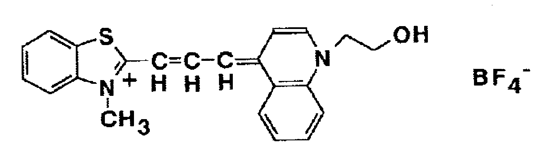
- The staining liquid contains a polymethine type fluorescent dye represented by the following structural formula. This dye has a property of being specifically bonded to a nucleic acid of bacteria, so that a staining liquid containing this dye can specifically stain the bacteria.
- The diluting liquid may have the following composition.
-
- Citric acid 100mM
- Sodium sulfate 90mM
- Amidosulfuric acid 100mM
- NaOH amount giving pH 1.5
-
- When the specimen and the reagents are set in this manner and a
start switch 5 is pressed, an overall control is started. Fig. 6 is a flowchart showing the flow of the overall control by the controlling programs. When the start switch is pressed, the steps S1 (analyte sample preparation), S2 (measurement), and S3 (analysis) are successively executed. Analytesample preparing section 7, measuringsection 8, and analyzingsection 35 are controlled by the controlling programs, whereby a series of operations are automatically carried out. The above-mentioned steps S1, S2, and S3 will be described below. - An operation of analyte
sample preparing section 7 in analyte sample preparation will be described with reference to Fig. 2. First, dispensing device 12 sucks a specimen from a specimen container set inspecimen setting section 9, and dispenses 50 µL into micro test tube 16 set in staining section 11. Next, dispensing device 12 sucks a diluting liquid frommicro test tube 15 set inreagent setting section 10, and dispenses 340 µL into micro test tube 16 set in staining section 11. Further, dispensing device 12 sucks a staining liquid from micro test tube 14 set inreagent setting section 10, and dispenses 10 µL into micro test tube 16 set in staining section 11. Thereafter, staining section 11 stirs the mixture for 30 seconds while maintaining micro test tube 16 at a temperature of 42°C. This prepares an analyte sample in micro test tube 16. - In the above-described preparation of an analyte sample, the specimen is processed under an acidic condition by using an acidic diluting liquid, and the bacteria in the specimen are stained. Fermentative bacteria produce an acidic product in decomposing sugar, as described in the Description of the Related Art. For this reason, fermentative bacteria can survive even under an acidic condition in which bacteria usually find difficult to live. On the other hand, non-fermentative bacteria die or suffer from damage of their cell membranes or cell walls under an acidic condition. Therefore, when a specimen is treated under an acidic condition, non-fermentative bacteria suffer from damage of their cell membranes or cell walls, so as to promote dye transmittance. This lets the substances in the cells of the non-fermentative bacteria be efficiently bonded to dyes. As a result of this, non-fermentative bacteria will have a higher degree of stainability than fermentative bacteria. In this embodiment, fluorescent staining is carried out, so that, by detecting fluorescence from each bacterium in the specimen, fermentative bacteria and non-fermentative bacteria can be easily distinguished by the difference of fluorescence intensity. In other words, the fluorescence intensity obtained from non-fermentative bacteria is higher than the fluorescence intensity obtained from fermentative bacteria. Here, the acidic condition shown above is preferably pH 1.0 to 3.0, most preferably 1.0 to 2.0.
- When the analyte sample is prepared, the analyte sample is sucked from micro test tube 16 of staining section 11 by liquid transporting device 13, and is sent to sheath flow cell 20 of measuring
section 8. - An operation of measuring
section 8 in the measurement will be described with reference to Figs. 3 and 4. The analyte sample prepared in analytesample preparing section 7 is guided to sheath flow cell 20, and the sample liquid is ejected into the sheath flow cell throughsample nozzle 30. Simultaneously with this, a sheath liquid is ejected into the sheath flow cell through sheath liquid supplying inlet 31. By this, the sample liquid is surrounded by the sheath liquid within the sheath flow cell, and is further narrowed down by narrow through-hole section 33 to flow. By narrowing the flow of the sample liquid to the same degree as the particle size, the particles contained in the sample liquid are arranged in one line to flow through the narrow through-hole section. - A laser beam emitted from
laser light source 21 is narrowed bycondenser lens 22 and is radiated onto the sample stream flowing through narrow through-hole section 33. The forward scattered light emitted from each particle in the sample that has received the laser beam is converged by converging lens 23 to pass throughpin hole 25. The side fluorescent light is converged by converging lens 24 to pass throughfilter 27 andpin hole 26. Then, the forward scattered light is received and undergoes photoelectric conversion byphotodiode 28, and the side fluorescent light is received and undergoes photoelectric conversion byphotomultiplier tube 29, and are output respectively as a forward scattered light signal and a side fluorescent light signal. Each signal is sent to controllingsection 6, and is stored intostorage section 34 as data of individual particles. - When a forward scattered light signal and a side fluorescent light signal are detected by the measurement of S2, analyzing
section 35 then analyzes each signal in accordance with the analyzing programs. An operation of the analyzing programs in S3 will be described with reference to the flowchart of Fig. 7. Each step in the flowchart is as follows. - S301: The data of the forward scattered light signal and the side fluorescent light
signal detected from the sample liquid are read out from
storage section 34. Then, the procedure goes to S302. - S302: The forward scattered light intensity (Fsc) and the side fluorescent light intensity (FL) are calculated on the basis of the forward scattered light signal and the side fluorescent light signal obtained from each particle in the sample liquid. Subsequently, the procedure goes to S303.
- S303: A scattergram is prepared using the Fsc and the FL of each particle calculated in S302 as parameters. This is carried out as follows. First, two-dimensional coordinates are developed taking the Fsc and the FL as axes, and then the coordinate position corresponding to each particle in the analyte sample is determined on the basis of the Fsc and the FL calculated in S302. In this manner, a scattergram is prepared using the Fsc and the FL as parameters. Then, the procedure goes to S304.
- S304: A region where non-fermentative bacteria appear (this is referred to as NF
region) and a region where fermentative bacteria appear (this is referred to as F region)
are set on the prepared scattergram. The manner in which these regions are set on the
scattergram is illustrated in Fig. 8. The NF region and the F region set here are
empirically determined beforehand by measuring analyte samples containing the
bacteria that are confirmed as non-fermentative bacteria and the bacteria that are
confirmed as fermentative bacteria. This allows that, if the principal bacteria
contained in a sample are non-fermentative bacteria, the dots corresponding to the
non-fermentative bacteria in the sample form a cluster and appear in the NF region.
On the other hand, if the principal bacteria contained in a sample are fermentative
bacteria, the dots corresponding to the fermentative bacteria in the sample form a cluster
and appear in the F region. Here, the data of coordinates in the NF region and the F
region, which are stored in
storage section 34, are read out by the analyzing programs in S304 and are applied onto the scattergram. Then, the procedure goes to S305. - S305: The number of dots in the NF region and in the F region is counted. Then, the procedure goes to S306.
- S306: The number of dots appearing within the NF region and the number of dots
appearing within the F region are compared, so as to determine which of the regions the
cluster of dots appears in. First, assuming the number of dots appearing in the NF
region to be NF and the number of dots appearing in the F region to be F, a value A is
determined by the following calculation formula:
- S307: The non-fermentative bacteria flag X is set to be "1". The procedure then goes to S309.
- S308: The non-fermentative bacteria flag X is set to be "0". The procedure then goes to S309.
- S309: In S309, a process of determining whether the non-fermentative bacteria flag X is "1" or not is executed. If the non-fermentative bacteria flag X is "1", the procedure goes to S310, whereas if the non-fermentative bacteria flag X is not "1", the procedure goes to S311.
- S310: The scattergram prepared in S303 and S304, the count results of the number
of dots in the NF region and in the F region counted in S305, and a message stating that
"the principal bacteria contained in the specimen are non-fermentative bacteria" are
displayed on liquid
crystal touch panel 2. - S311: The scattergram prepared in S303 and S304, the count results of the number
of dots in the NF region and in the F region counted in S305, and a message stating that
"the principal bacteria contained in the specimen are fermentative bacteria" are
displayed on liquid
crystal touch panel 2. -
- The above is the flowchart of the measurement in this embodiment.
- As described above, Fig. 8 is a view for describing the scattergram prepared in S303 and S304. In the scattergram, the axis of abscissa represents the FL, and the axis of ordinate represents the Fsc. In the axis of abscissa, the right side has a larger value of FL. In the axis of ordinate, the upper side has a larger value of Fsc. The non-fermentative bacteria appear within the NF region that is set on the scattergram. On the other hand, the fermentative bacteria appear within the F region that is set on the scattergram. Here, as described above, the non-fermentative bacteria have a higher degree of fluorescence stainability than the fermentative bacteria. Therefore, the fluorescence intensity detected from the non-fermentative bacteria is higher than the fluorescence intensity detected from the fermentative bacteria. For this reason, the NF region is set at a position corresponding to higher fluorescence intensity than the F region.
- Hereafter, an example of the results of analyzing a specimen using
bacteria analyzing apparatus 1 will be shown. - A specimen was prepared as follows. First, bacteria were cultivated in an agarose medium to form a colony of bacteria. Then, an intended kind of bacteria are collected from the colony, and are suspended into a heart infusion liquid medium so that the number of bacteria will have a concentration of about 105/ml. In this example, bacteria liquid was prepared for each of the seven kinds of bacteria in all, and used as a specimen. Among the seven kinds of bacteria, the fermentative bacteria are four kinds including E. coli, K. pneumoniae, L. achidophilus, and S. aureus. The non-fermentative bacteria are three kinds including P. aeruginosa, A. baumannii, and E. faecalis. The scattergram obtained by analyzing the bacteria liquid of each of the bacteria prepared by the aforementioned method using
bacteria analyzing apparatus 1 is shown in Figs. 9 and 10. - Fig. 9A to 9D are scattergrams obtained using the bacteria liquid of the fermentative bacteria as a specimen. Fig. 9A shows a scattergram obtained by analyzing the bacteria liquid of E. coli. Fig. 9B shows a scattergram obtained by analyzing the bacteria liquid of K. pneumoniae. Fig. 9C shows a scattergram obtained by analyzing the bacteria liquid of S. aureus. Fig. 9D shows a scattergram obtained by analyzing the bacteria liquid of L. achidophilus. In all of Fig. 9A, 9B, 9C and 9D, a cluster of dots is seen in the F region where fermentative bacteria appear.
- Fig. 10A to 10C are scattergrams obtained using the bacteria liquid of the non-fermentative bacteria as a specimen. Fig. 10A shows a scattergram obtained by analyzing the bacteria liquid of P. aeruginosa. Fig. 10B shows a scattergram obtained by analyzing the bacteria liquid of A. baumannii. Fig. 10C shows a scattergram obtained by analyzing the bacteria liquid of E. faecalis. In all of Fig. 10A, 10B and 10C, a cluster of dots is seen in the NF region where non-fermentative bacteria appear.
- By Figs. 9 and 10, it has been confirmed that the cluster of non-fermentative bacteria appears in the NF region where non-fermentative bacteria appear, and that the cluster of fermentative bacteria appears in the F region where fermentative bacteria appear. Thus, since the sites of appearance of fermentative bacteria and non-fermentative bacteria differ greatly on the scattergram, the fermentative bacteria can be easily distinguished from the non-fermentative bacteria.
- The Methyl Red reaction test shown as a prior art in the above description requires cultivation for examining whether the bacteria decompose sugar or not in order to detect fermentative bacteria. For this reason, it requires two or three days before the fermentative bacteria are detected. In contrast,
bacteria analyzing apparatus 1 eliminates the need for cultivation to examine whether the bacteria decompose sugar or not. Therefore, with the use ofbacteria analyzing apparatus 1, the prepared bacteria liquid can be used as a specimen for measurement, and the results can be obtained at once. - Next, an example of the results obtained by analyzing urine collected from a patient as a specimen using
bacteria analyzing apparatus 1 will be described below. - The specimens put to use were four specimens from A to D. Specimen A is urine of a human containing E. coli (fermentative bacteria); specimen B is urine of a human containing S. aureus (fermentative bacteria); specimen C is urine of a human containing E. faecalis (non-fermentative bacteria); and specimen D is urine of a human containing P. aeruginosa (non-fermentative bacteria).
- The scattergrams obtained by analyzing the above-described four specimens from A to D with the use of
bacteria analyzing apparatus 1 are shown in Fig. 11A to 11D. Fig. 11A shows a scattergram obtained by analyzing specimen A. Fig. 11B shows a scattergram obtained by analyzing specimen B. Fig. 11C shows a scattergram obtained by analyzing specimen C. Fig. 11D shows a scattergram obtained by analyzing specimen D. Regarding specimen A and specimen B, the cluster of dots appears in all cases in the F region where fermentative bacteria appear. On the other hand, regarding specimen C and specimen D, the cluster of dots appears in all cases in the NF region where non-fermentative bacteria appear. - The results of determination whether the principal bacteria contained in a specimen are fermentative bacteria or non-fermentative bacteria with the use of
bacteria analyzing apparatus 1 on the basis of the appearance regions of the cluster of dots in a scattergram are shown in the following table.Specimen Determination result A Fermentative bacteria B Fermentative bacteria C Non-fermentative bacteria D Non-fermentative bacteria - As shown in Table 1, the principal bacteria contained in the urine of specimen A and specimen B were determined to be fermentative bacteria, and the principal bacteria contained in the urine of specimen C and specimen D were determined to be non-fermentative bacteria. Also, in all of the cases of specimen A, specimen B, specimen C, and specimen D, the results of determination of the bacteria kind based on the analysis results coincide with the kinds of bacteria that are really contained in each specimen.
- In the above-described embodiment, the fermentative bacteria and the non-fermentative bacteria contained in a specimen can be speedily detected to determine whether the principal bacteria contained in the specimen are fermentative bacteria or non-fermentative bacteria. The Methyl Red reaction test shown as a prior art in the above description requires cultivation for examining whether the bacteria decompose sugar or not, so that it requires two or three days before the fermentative bacteria are detected. In contrast, the present embodiment eliminates the need for cultivation to examine whether the bacteria decompose sugar or not, so that the prepared bacteria liquid can be used as a specimen for measurement, and the results can be obtained at once.
- Further, in the above-described embodiment, the urine or blood collected from a patient can be used, as it is, as a specimen for measurement, without preparing a bacteria liquid such as described above. This allows that one can speedily determine whether the kind of the principal bacteria contained in a specimen is fermentative bacteria or non-fermentative bacteria.
- Here,
bacteria analyzing apparatus 1 of the above-described embodiment is an apparatus in which all the constituents are integrated; however, the present invention is not limited to this construction alone. For example, it may be an apparatus such as shown in Fig. 12 in which a part of the constituents are separately provided. Abacteria analyzing apparatus 37 of Fig. 12 is made of a measuring apparatusmain body 38 and apersonal computer 39. Further, though not illustrated in the drawings, measuring apparatusmain body 38 has a start switch, an analyte sample preparing section for preparing a sample liquid, a measuring section for detecting signals from the sample liquid, and a first controlling section that controls the operation of the apparatus. The first controlling section has a first storage section that stores controlling programs for controlling the operation of each device and an operation controlling section for controlling the operation of each device in accordance with the controlling programs stored in the first storage section.Personal computer 39 has anoutput screen 40 for outputting and displaying the measurement results, an input section 41 for performing various setting inputs, and a second controlling section 42 that controls an analysis process. Second controlling section 42 has a second storage section for storing the analyzing programs and the results of processing by the analyzing programs, and an analyzing section for performing analysis on the basis of the data obtained by the measurement. Measuring apparatusmain body 38 andpersonal computer 39 of Fig. 12 are connected via a connective device. The operation of each section in measurement apparatusmain body 38 is controlled in accordance with the first controlling section of measuring apparatusmain body 38. The measurement data obtained in measuring apparatusmain body 38 are stored into the second storage section ofpersonal computer 39 and analyzed by the analyzing section. - Further, in the analysis (S3) of
bacteria analyzing apparatus 1 of the above-described embodiment, the region (F region) where the dots corresponding to fermentative bacteria appear and the region (NF region) where the dots corresponding to non-fermentative bacteria appear are both set on the scattergram; however, the present invention is not limited to this alone. For example, on the scattergram, one may set only the region (NF region) where the dots corresponding to non-fermentative bacteria appear. In this case, the non-fermentative bacteria contained in a specimen are detected by determining whether the dots appear in the NF region that is set on the scattergram. - Further, in the analysis (S3) of
bacteria analyzing apparatus 1 of the above-described embodiment, whether the principal bacteria contained in a specimen are fermentative bacteria or non-fermentative bacteria is determined; however, the present invention is not limited to this alone. For example, in the case of analyzing a "specimen containing only one kind of bacteria" such as used in the measurement example 1, the bacteria of the specimen can be classified to either fermentative bacteria or non-fermentative bacteria, since it is clear that the bacteria contained in the specimen is only one kind. Therefore, in this case, whether the kind of bacteria contained in the specimen is fermentative bacteria or non-fermentative bacteria may be determined in the analysis (S3). - In addition, in the analysis (S3) of
bacteria analyzing apparatus 1 of the above-described embodiment, the number of fermentative bacteria and the number of non-fermentative bacteria contained in a specimen may further be calculated. On the scattergram, the dots corresponding to fermentative bacteria appear in the F region and the dots corresponding to non-fermentative bacteria appear in the NF region. This allows that the number of fermentative bacteria and the number of non-fermentative bacteria contained in a specimen can be calculated on the basis of the number of dots appearing in the F region and the number of dots appearing in the NF region. - Further, in the case of performing measurement using a "specimen containing only one kind of bacteria", the number of bacteria may be calculated only for the bacteria that are determined in the analysis step. For example, if it is determined that the principal bacteria contained in a specimen are non-fermentative bacteria in the analysis step, the number of non-fermentative bacteria contained in the specimen is calculated on the basis of the number of dots appearing in the NF region, without calculating the number of fermentative bacteria. On the other hand, if it is determined that the principal bacteria contained in a specimen are fermentative bacteria in the analysis step, the number of fermentative bacteria contained in the specimen is calculated on the basis of the number of dots appearing in the F region, without calculating the number of non-fermentative bacteria.
- Further, in the case of performing measurement using a "specimen containing bacteria and particles other than bacteria" such as urine, the particles other than bacteria (hereafter referred to as impurities) may be stained together with the bacteria, and the dots corresponding to the impurities may appear in the F region. Therefore, in calculating the number of fermentative bacteria contained in a specimen on the basis of the number of dots appearing in the F region, the correct number of fermentative bacteria may not be calculated due to the influence of the impurities. Thus, in performing measurement using a "specimen containing bacteria and impurities", the analysis step may calculate only the number of non-fermentative bacteria without calculating the number of fermentative bacteria. In this case, the number of non-fermentative bacteria contained in the specimen is calculated on the basis of the number of dots appearing in the NF region.
- Further, even if a "specimen containing bacteria and impurities" is used for measurement, the number of fermentative bacteria can be determined on condition that the total number of bacteria contained in the specimen can be determined. In this case, in the analysis step, the number of non-fermentative bacteria contained in the specimen is calculated on the basis of the number of dots appearing in the NF region. Then, by subtracting the number of non-fermentative bacteria from the total number of bacteria determined in advance, the number of fermentative bacteria contained in the specimen is calculated. Here, the total number of bacteria contained in the specimen can be determined, for example, by using a method disclosed in European Patent Publication No. 1136563.
Claims (19)
- An apparatus for analyzing bacteria, comprising:an analyte sample preparing section for preparing an analyte sample from a specimen;a detector for detecting optical information from each particle in the analyte sample; anda controller for detecting non-fermentative bacteria on the basis of the detected optical information.
- The apparatus according to claim 1, wherein said controlling section detects fermentative bacteria and non-fermentative bacteria in the sample on the basis of the detected optical information.
- An apparatus for analyzing bacteria, comprising:an analyte sample preparing section for preparing an analyte sample from a specimen;a detector for detecting optical information from each particle in the analyte sample; anda controller for determining whether the kind of bacteria contained in the specimen is fermentative bacteria or non-fermentative bacteria on the basis of the detected optical information.
- The apparatus according to claim 1 or 3, wherein said analyte sample preparing section performs fluorescent staining on the specimen so as to generate difference in fluorescence intensity between fermentative bacteria and non-fermentative bacteria.
- The apparatus according to claim 1 or 3, wherein said analyte sample preparing section prepares the analyte sample by treating the specimen under an acidic condition.
- The apparatus according to claim 1 or 3, wherein said analyte sample preparing section comprises a liquid mixing mechanism for mixing an acidic solution with the specimen.
- The apparatus according to claim 1 or 3, wherein said analyte sample preparing section performs fluorescent staining on the specimen treated under an acidic condition.
- The apparatus according to claim 1 or 3, wherein said analyte sample preparing section comprises a liquid mixing mechanism for mixing an acidic solution with the specimen, and for mixing the obtained mixture with a reagent which contains fluorescent dye.
- The apparatus according to claim 4, 7 or 8, wherein the optical information detected by said detecting section includes fluorescence.
- The apparatus according to claim 1, wherein said controller calculates the number of non-fermentative bacterial on the basis of the detected optical information.
- The apparatus according to claim 2, wherein said controller calculates the number of non-fermentative bacterial and the number of fermentative bacteria on the basis of the detected optical information.
- The apparatus according to claim 3, wherein said controller determines whether principal bacteria contained in the specimen are fermentative bacteria or non-fermentative bacteria on the basis of the detected optical information.
- The apparatus according to claim 3, wherein said controller detects fermentative bacteria and non-fermentative bacteria on the basis of the detected optical information and determines whether the kind of bacteria contained in the specimen is fermentative bacteria or non-fermentative bacteria in accordance with a result of detecting the fermentative bacteria and non-fermentative bacteria.
- The apparatus according to claim 3, wherein said controller detects fermentative bacteria and non-fermentative bacteria on the basis of the detected optical information and determines whether principal bacteria contained in the specimen are fermentative bacteria or non-fermentative bacteria on the basis of a result of detecting the fermentative bacteria and non-fermentative bacteria.
- A method for bacteria analyzing, comprising:an analyte sample preparing step for preparing an analyte sample from a specimen;a detecting step for detecting optical information from each particle in the analyte sample;anda bacteria detecting step for detecting non-fermentative bacteria on the basis of the detected optical information.
- The method according to claim 15, further comprising a calculating step for calculating the number of detected non-fermentative bacteria.
- The method according to claim 15, further comprising a first calculating step for determining the total number of bacteria contained in the specimen, a second calculating step for calculating the number of detected non-fermentative bacteria, and a third calculating step for calculating the number of fermentative bacteria on the basis of the total number of bacteria and the number of non-fermentative bacteria.
- The method according to claim 15, wherein the bacteria detecting step detects fermentative bacteria and non-fermentative bacteria on the basis of the detected optical information, and further comprising a determining step for determining whether the kind of bacteria contained in the specimen is fermentative bacteria or non-fermentative bacteria on the basis of a result of detecting the fermentative bacteria and non-fermentative bacteria.
- A method for bacteria analyzing, comprising:an analyte sample preparing step for preparing an analyte sample from a specimen;a detecting step for detecting optical information from each particle in the analyte sample; anda determining step for determining whether the kind of bacteria contained in the specimen is fermentative bacteria or non-fermentative bacteria on the basis of the detected optical information.
Applications Claiming Priority (2)
| Application Number | Priority Date | Filing Date | Title |
|---|---|---|---|
| JP2003299208 | 2003-08-22 | ||
| JP2003299208A JP4448673B2 (en) | 2003-08-22 | 2003-08-22 | Bacteria analyzer and method |
Publications (2)
| Publication Number | Publication Date |
|---|---|
| EP1508621A1 true EP1508621A1 (en) | 2005-02-23 |
| EP1508621B1 EP1508621B1 (en) | 2007-02-14 |
Family
ID=34056275
Family Applications (1)
| Application Number | Title | Priority Date | Filing Date |
|---|---|---|---|
| EP04019716A Expired - Fee Related EP1508621B1 (en) | 2003-08-22 | 2004-08-19 | Apparatus and method for analyzing bacteria |
Country Status (4)
| Country | Link |
|---|---|
| US (1) | US7582473B2 (en) |
| EP (1) | EP1508621B1 (en) |
| JP (1) | JP4448673B2 (en) |
| DE (1) | DE602004004708T2 (en) |
Cited By (1)
| Publication number | Priority date | Publication date | Assignee | Title |
|---|---|---|---|---|
| EP2144047A3 (en) * | 2008-07-08 | 2012-03-28 | Sysmex Corporation | Bacteria analyzer, bacteria analyzing method and computer program product |
Families Citing this family (6)
| Publication number | Priority date | Publication date | Assignee | Title |
|---|---|---|---|---|
| JP4236893B2 (en) * | 2002-10-04 | 2009-03-11 | シスメックス株式会社 | Bacteria counting method and bacteria counting apparatus |
| US20070141597A1 (en) * | 2005-10-25 | 2007-06-21 | Harmon H J | Biomimetic Biodetector of Toxins, Viruses, Bacteria, and Biological Factors |
| US20100028853A1 (en) * | 2005-10-25 | 2010-02-04 | Harold James Harmon | Optical determination of living vs. non living cells |
| US8512975B2 (en) * | 2008-07-24 | 2013-08-20 | Biomerieux, Inc. | Method for detection and characterization of a microorganism in a sample using time dependent spectroscopic measurements |
| CN102639986A (en) * | 2009-08-27 | 2012-08-15 | 夏普株式会社 | Display control device |
| EP2348301B1 (en) * | 2010-01-08 | 2013-08-21 | Sysmex Corporation | Sample analyzer |
Citations (5)
| Publication number | Priority date | Publication date | Assignee | Title |
|---|---|---|---|---|
| US5236827A (en) * | 1988-06-20 | 1993-08-17 | Becton, Dickinson And Company | Device for enhancing fluorescence and kinetics and methods of using the device |
| EP0818540A1 (en) * | 1995-03-28 | 1998-01-14 | Idemitsu Kosan Company Limited | Method for rapidly determining number of bacteria and equipment for determining number of bacteria |
| WO2000070078A2 (en) * | 1999-05-12 | 2000-11-23 | Fraunhofer-Gesellschaft zur Förderung der angewandten Forschung e.V. | Method and device for determining the concentration of organisms |
| EP1203825A2 (en) * | 2000-11-01 | 2002-05-08 | Sysmex Corporation | Method of staining, detecting and counting bacteria, and a diluent for bacterial stain |
| US20020148729A1 (en) * | 2000-06-23 | 2002-10-17 | Daniel Armstrong | Method for separation, identification and evaluation of microbes and cells |
Family Cites Families (6)
| Publication number | Priority date | Publication date | Assignee | Title |
|---|---|---|---|---|
| JP3067849B2 (en) * | 1991-07-29 | 2000-07-24 | シスメックス株式会社 | Sample preparation method for leukocyte classification and counting |
| US5656499A (en) * | 1994-08-01 | 1997-08-12 | Abbott Laboratories | Method for performing automated hematology and cytometry analysis |
| US6070093A (en) * | 1997-12-02 | 2000-05-30 | Abbott Laboratories | Multiplex sensor and method of use |
| US6911313B2 (en) * | 1998-02-06 | 2005-06-28 | Sysmex Corporation | Process for discriminating and counting erythroblasts |
| US7001733B1 (en) * | 1998-05-12 | 2006-02-21 | Rigel Pharmaceuticals, Inc. | Methods and compositions for screening for modulations of IgE synthesis, secretion and switch rearrangement |
| JP3837006B2 (en) | 2000-03-22 | 2006-10-25 | シスメックス株式会社 | Bacterial staining method and detection method |
-
2003
- 2003-08-22 JP JP2003299208A patent/JP4448673B2/en not_active Expired - Fee Related
-
2004
- 2004-08-19 DE DE602004004708T patent/DE602004004708T2/en active Active
- 2004-08-19 EP EP04019716A patent/EP1508621B1/en not_active Expired - Fee Related
- 2004-08-19 US US10/922,522 patent/US7582473B2/en not_active Expired - Fee Related
Patent Citations (5)
| Publication number | Priority date | Publication date | Assignee | Title |
|---|---|---|---|---|
| US5236827A (en) * | 1988-06-20 | 1993-08-17 | Becton, Dickinson And Company | Device for enhancing fluorescence and kinetics and methods of using the device |
| EP0818540A1 (en) * | 1995-03-28 | 1998-01-14 | Idemitsu Kosan Company Limited | Method for rapidly determining number of bacteria and equipment for determining number of bacteria |
| WO2000070078A2 (en) * | 1999-05-12 | 2000-11-23 | Fraunhofer-Gesellschaft zur Förderung der angewandten Forschung e.V. | Method and device for determining the concentration of organisms |
| US20020148729A1 (en) * | 2000-06-23 | 2002-10-17 | Daniel Armstrong | Method for separation, identification and evaluation of microbes and cells |
| EP1203825A2 (en) * | 2000-11-01 | 2002-05-08 | Sysmex Corporation | Method of staining, detecting and counting bacteria, and a diluent for bacterial stain |
Cited By (1)
| Publication number | Priority date | Publication date | Assignee | Title |
|---|---|---|---|---|
| EP2144047A3 (en) * | 2008-07-08 | 2012-03-28 | Sysmex Corporation | Bacteria analyzer, bacteria analyzing method and computer program product |
Also Published As
| Publication number | Publication date |
|---|---|
| DE602004004708D1 (en) | 2007-03-29 |
| EP1508621B1 (en) | 2007-02-14 |
| DE602004004708T2 (en) | 2007-11-29 |
| US20050042744A1 (en) | 2005-02-24 |
| JP4448673B2 (en) | 2010-04-14 |
| JP2005065573A (en) | 2005-03-17 |
| US7582473B2 (en) | 2009-09-01 |
Similar Documents
| Publication | Publication Date | Title |
|---|---|---|
| US7892850B2 (en) | Apparatus and method for measuring immature platelets | |
| US9422588B2 (en) | Bacteria measuring apparatuses | |
| EP1746407A2 (en) | Blood analyzing method and blood analyzer | |
| EP2028495B1 (en) | Sample analyzer, sample analyzing method, and computer program product | |
| US8647859B2 (en) | Apparatus and method for analyzing bacteria | |
| EP2261632B1 (en) | Sample preparation device, and cell analyzing device with the same | |
| US20060073606A1 (en) | Measurement result correction method, urine analysis system, urine analyzer, and storage medium | |
| US9046505B2 (en) | Sample preparation apparatus | |
| EP2293062A1 (en) | Blood analyzer, blood analysis method, hemolytic agent and staining agent | |
| US20120214224A1 (en) | Flow based clinical analysis | |
| JP4751535B2 (en) | Fractionation method and blood analyzer using the same | |
| EP1508621B1 (en) | Apparatus and method for analyzing bacteria | |
| JP4509607B2 (en) | Cell analysis apparatus and method | |
| JP2005017254A (en) | Platelet aggregation test apparatus | |
| EP1553410B1 (en) | Apparatus for immunoassays and application thereof | |
| JP4503370B2 (en) | Formed component analysis apparatus and method | |
| JP2005333868A (en) | Method and device for measuring malaria parasite | |
| JP2004290119A (en) | Method and apparatus for analyzing bacterium | |
| CN116338156A (en) | Liquid path system for analyzing microparticles by using multi-methodology | |
| CN116008133A (en) | Blood analyzer and blood analysis method | |
| JP2893613B2 (en) | Micronucleus cell analysis method and micronucleus cell analyzer |
Legal Events
| Date | Code | Title | Description |
|---|---|---|---|
| PUAI | Public reference made under article 153(3) epc to a published international application that has entered the european phase |
Free format text: ORIGINAL CODE: 0009012 |
|
| AK | Designated contracting states |
Kind code of ref document: A1 Designated state(s): AT BE BG CH CY CZ DE DK EE ES FI FR GB GR HU IE IT LI LU MC NL PL PT RO SE SI SK TR |
|
| AX | Request for extension of the european patent |
Extension state: AL HR LT LV MK |
|
| 17P | Request for examination filed |
Effective date: 20050615 |
|
| AKX | Designation fees paid |
Designated state(s): DE GB IT |
|
| GRAP | Despatch of communication of intention to grant a patent |
Free format text: ORIGINAL CODE: EPIDOSNIGR1 |
|
| GRAS | Grant fee paid |
Free format text: ORIGINAL CODE: EPIDOSNIGR3 |
|
| GRAA | (expected) grant |
Free format text: ORIGINAL CODE: 0009210 |
|
| AK | Designated contracting states |
Kind code of ref document: B1 Designated state(s): DE GB IT |
|
| REG | Reference to a national code |
Ref country code: GB Ref legal event code: FG4D |
|
| REF | Corresponds to: |
Ref document number: 602004004708 Country of ref document: DE Date of ref document: 20070329 Kind code of ref document: P |
|
| PLBE | No opposition filed within time limit |
Free format text: ORIGINAL CODE: 0009261 |
|
| STAA | Information on the status of an ep patent application or granted ep patent |
Free format text: STATUS: NO OPPOSITION FILED WITHIN TIME LIMIT |
|
| 26N | No opposition filed |
Effective date: 20071115 |
|
| PGFP | Annual fee paid to national office [announced via postgrant information from national office to epo] |
Ref country code: IT Payment date: 20100819 Year of fee payment: 7 |
|
| PG25 | Lapsed in a contracting state [announced via postgrant information from national office to epo] |
Ref country code: IT Free format text: LAPSE BECAUSE OF NON-PAYMENT OF DUE FEES Effective date: 20110819 |
|
| PGFP | Annual fee paid to national office [announced via postgrant information from national office to epo] |
Ref country code: DE Payment date: 20140813 Year of fee payment: 11 |
|
| PGFP | Annual fee paid to national office [announced via postgrant information from national office to epo] |
Ref country code: GB Payment date: 20140813 Year of fee payment: 11 |
|
| REG | Reference to a national code |
Ref country code: DE Ref legal event code: R119 Ref document number: 602004004708 Country of ref document: DE |
|
| GBPC | Gb: european patent ceased through non-payment of renewal fee |
Effective date: 20150819 |
|
| PG25 | Lapsed in a contracting state [announced via postgrant information from national office to epo] |
Ref country code: GB Free format text: LAPSE BECAUSE OF NON-PAYMENT OF DUE FEES Effective date: 20150819 Ref country code: DE Free format text: LAPSE BECAUSE OF NON-PAYMENT OF DUE FEES Effective date: 20160301 |