EP1507415A2 - Video encoding/decoding apparatus and method for color image - Google Patents
Video encoding/decoding apparatus and method for color image Download PDFInfo
- Publication number
- EP1507415A2 EP1507415A2 EP20040254270 EP04254270A EP1507415A2 EP 1507415 A2 EP1507415 A2 EP 1507415A2 EP 20040254270 EP20040254270 EP 20040254270 EP 04254270 A EP04254270 A EP 04254270A EP 1507415 A2 EP1507415 A2 EP 1507415A2
- Authority
- EP
- European Patent Office
- Prior art keywords
- image
- input image
- color component
- prediction
- component
- Prior art date
- Legal status (The legal status is an assumption and is not a legal conclusion. Google has not performed a legal analysis and makes no representation as to the accuracy of the status listed.)
- Ceased
Links
- 238000000034 method Methods 0.000 title claims abstract description 66
- 238000001514 detection method Methods 0.000 claims abstract description 14
- 238000001914 filtration Methods 0.000 claims description 28
- 230000000694 effects Effects 0.000 claims description 19
- 238000013139 quantization Methods 0.000 claims description 7
- 238000010187 selection method Methods 0.000 claims description 5
- 238000004590 computer program Methods 0.000 claims 1
- 241000023320 Luma <angiosperm> Species 0.000 description 12
- 238000010586 diagram Methods 0.000 description 12
- OSWPMRLSEDHDFF-UHFFFAOYSA-N methyl salicylate Chemical compound COC(=O)C1=CC=CC=C1O OSWPMRLSEDHDFF-UHFFFAOYSA-N 0.000 description 12
- 230000006835 compression Effects 0.000 description 10
- 238000007906 compression Methods 0.000 description 10
- 101150039623 Clip1 gene Proteins 0.000 description 9
- 238000004088 simulation Methods 0.000 description 6
- 238000012886 linear function Methods 0.000 description 3
- 230000002123 temporal effect Effects 0.000 description 3
- 238000012935 Averaging Methods 0.000 description 2
- 238000007796 conventional method Methods 0.000 description 2
- 230000003247 decreasing effect Effects 0.000 description 2
- 230000002708 enhancing effect Effects 0.000 description 2
- 238000013459 approach Methods 0.000 description 1
- 230000005540 biological transmission Effects 0.000 description 1
- 238000012545 processing Methods 0.000 description 1
Images


Classifications
-
- H—ELECTRICITY
- H04—ELECTRIC COMMUNICATION TECHNIQUE
- H04N—PICTORIAL COMMUNICATION, e.g. TELEVISION
- H04N19/00—Methods or arrangements for coding, decoding, compressing or decompressing digital video signals
- H04N19/85—Methods or arrangements for coding, decoding, compressing or decompressing digital video signals using pre-processing or post-processing specially adapted for video compression
- H04N19/86—Methods or arrangements for coding, decoding, compressing or decompressing digital video signals using pre-processing or post-processing specially adapted for video compression involving reduction of coding artifacts, e.g. of blockiness
-
- H—ELECTRICITY
- H04—ELECTRIC COMMUNICATION TECHNIQUE
- H04N—PICTORIAL COMMUNICATION, e.g. TELEVISION
- H04N19/00—Methods or arrangements for coding, decoding, compressing or decompressing digital video signals
- H04N19/50—Methods or arrangements for coding, decoding, compressing or decompressing digital video signals using predictive coding
- H04N19/503—Methods or arrangements for coding, decoding, compressing or decompressing digital video signals using predictive coding involving temporal prediction
- H04N19/51—Motion estimation or motion compensation
-
- H—ELECTRICITY
- H04—ELECTRIC COMMUNICATION TECHNIQUE
- H04N—PICTORIAL COMMUNICATION, e.g. TELEVISION
- H04N19/00—Methods or arrangements for coding, decoding, compressing or decompressing digital video signals
- H04N19/10—Methods or arrangements for coding, decoding, compressing or decompressing digital video signals using adaptive coding
- H04N19/102—Methods or arrangements for coding, decoding, compressing or decompressing digital video signals using adaptive coding characterised by the element, parameter or selection affected or controlled by the adaptive coding
- H04N19/103—Selection of coding mode or of prediction mode
- H04N19/105—Selection of the reference unit for prediction within a chosen coding or prediction mode, e.g. adaptive choice of position and number of pixels used for prediction
-
- H—ELECTRICITY
- H04—ELECTRIC COMMUNICATION TECHNIQUE
- H04N—PICTORIAL COMMUNICATION, e.g. TELEVISION
- H04N19/00—Methods or arrangements for coding, decoding, compressing or decompressing digital video signals
- H04N19/10—Methods or arrangements for coding, decoding, compressing or decompressing digital video signals using adaptive coding
- H04N19/102—Methods or arrangements for coding, decoding, compressing or decompressing digital video signals using adaptive coding characterised by the element, parameter or selection affected or controlled by the adaptive coding
- H04N19/117—Filters, e.g. for pre-processing or post-processing
-
- H—ELECTRICITY
- H04—ELECTRIC COMMUNICATION TECHNIQUE
- H04N—PICTORIAL COMMUNICATION, e.g. TELEVISION
- H04N19/00—Methods or arrangements for coding, decoding, compressing or decompressing digital video signals
- H04N19/10—Methods or arrangements for coding, decoding, compressing or decompressing digital video signals using adaptive coding
- H04N19/169—Methods or arrangements for coding, decoding, compressing or decompressing digital video signals using adaptive coding characterised by the coding unit, i.e. the structural portion or semantic portion of the video signal being the object or the subject of the adaptive coding
- H04N19/17—Methods or arrangements for coding, decoding, compressing or decompressing digital video signals using adaptive coding characterised by the coding unit, i.e. the structural portion or semantic portion of the video signal being the object or the subject of the adaptive coding the unit being an image region, e.g. an object
- H04N19/176—Methods or arrangements for coding, decoding, compressing or decompressing digital video signals using adaptive coding characterised by the coding unit, i.e. the structural portion or semantic portion of the video signal being the object or the subject of the adaptive coding the unit being an image region, e.g. an object the region being a block, e.g. a macroblock
-
- H—ELECTRICITY
- H04—ELECTRIC COMMUNICATION TECHNIQUE
- H04N—PICTORIAL COMMUNICATION, e.g. TELEVISION
- H04N19/00—Methods or arrangements for coding, decoding, compressing or decompressing digital video signals
- H04N19/10—Methods or arrangements for coding, decoding, compressing or decompressing digital video signals using adaptive coding
- H04N19/169—Methods or arrangements for coding, decoding, compressing or decompressing digital video signals using adaptive coding characterised by the coding unit, i.e. the structural portion or semantic portion of the video signal being the object or the subject of the adaptive coding
- H04N19/186—Methods or arrangements for coding, decoding, compressing or decompressing digital video signals using adaptive coding characterised by the coding unit, i.e. the structural portion or semantic portion of the video signal being the object or the subject of the adaptive coding the unit being a colour or a chrominance component
-
- H—ELECTRICITY
- H04—ELECTRIC COMMUNICATION TECHNIQUE
- H04N—PICTORIAL COMMUNICATION, e.g. TELEVISION
- H04N19/00—Methods or arrangements for coding, decoding, compressing or decompressing digital video signals
- H04N19/50—Methods or arrangements for coding, decoding, compressing or decompressing digital video signals using predictive coding
- H04N19/503—Methods or arrangements for coding, decoding, compressing or decompressing digital video signals using predictive coding involving temporal prediction
- H04N19/51—Motion estimation or motion compensation
- H04N19/523—Motion estimation or motion compensation with sub-pixel accuracy
-
- H—ELECTRICITY
- H04—ELECTRIC COMMUNICATION TECHNIQUE
- H04N—PICTORIAL COMMUNICATION, e.g. TELEVISION
- H04N19/00—Methods or arrangements for coding, decoding, compressing or decompressing digital video signals
- H04N19/50—Methods or arrangements for coding, decoding, compressing or decompressing digital video signals using predictive coding
- H04N19/503—Methods or arrangements for coding, decoding, compressing or decompressing digital video signals using predictive coding involving temporal prediction
- H04N19/51—Motion estimation or motion compensation
- H04N19/527—Global motion vector estimation
-
- H—ELECTRICITY
- H04—ELECTRIC COMMUNICATION TECHNIQUE
- H04N—PICTORIAL COMMUNICATION, e.g. TELEVISION
- H04N19/00—Methods or arrangements for coding, decoding, compressing or decompressing digital video signals
- H04N19/50—Methods or arrangements for coding, decoding, compressing or decompressing digital video signals using predictive coding
- H04N19/593—Methods or arrangements for coding, decoding, compressing or decompressing digital video signals using predictive coding involving spatial prediction techniques
-
- H—ELECTRICITY
- H04—ELECTRIC COMMUNICATION TECHNIQUE
- H04N—PICTORIAL COMMUNICATION, e.g. TELEVISION
- H04N19/00—Methods or arrangements for coding, decoding, compressing or decompressing digital video signals
- H04N19/60—Methods or arrangements for coding, decoding, compressing or decompressing digital video signals using transform coding
- H04N19/61—Methods or arrangements for coding, decoding, compressing or decompressing digital video signals using transform coding in combination with predictive coding
Definitions
- a video decoding apparatus comprising: a first restoration unit performing a predetermined operation for an encoded image and generating a first prediction residue image of the encoded image; an image information detection unit determining whether the encoded image is an R-G-B image or a Y-Cb-Cr image and whether or not a color component of the encoded image is a reference color component of the R-G-B image; a second restoration unit generating a second prediction residue image of the encoded image, on the basis of the reference color component, if the encoded image is the R-G-B image and if the color component of the encoded image is not the reference color component; a deblocking filter unit reducing block effect of a decoded image that influences an encoded image restored on the basis of the first prediction residue image and the second prediction residue image.
- a motion compensation method which is performed by an encoder or decoder, comprising: detecting color information of an input image; selecting a length of a filter tap for interpolation on the basis of the color information of the input image; interpolating the input image using a filter tap with the selected length; and performing motion compensation for the interpolated result.
- a motion compensation method which is performed by a decoder or encoder, comprising: detecting resolution information and color information of an input image; selecting a length of a filter tap for interpolation on the basis of the resolution information and color information of the input image; interpolating the input image using a filter tap with the selected length; and performing motion compensation for the interpolated result.
- the present invention also provides a deblocking filter for efficiently reducing block efficiency according to color information and resolution information upon video encoding/decoding, and a deblocking filtering method therefor.
- a deblocking filter apparatus which is included in a video decoder or video encoder, comprising: an image information detector detecting color information of an image; a deblocking filter selector selecting a length of a deblocking filter tap for reducing block effect of the image on the basis of the color information; a filtering unit filtering the image using a deblocking filter with the selected tap length.
- a deblocking filter selection method which is performed by a decoder or encoder, comprising: detecting color information of an image; selecting a length of a deblocking filer for reducing block effect of the image on the basis of the color information; and filtering the image using a deblocking filter with the selected length.
- FIG. 1a is a block diagram showing a structure of a video encoding apparatus according to an embodiment of the present invention.
- the video encoding apparatus includes a first motion prediction unit 100, an image information detection unit 110, a second motion prediction unit 120, and an encoding unit 130.
- the first motion prediction unit 100 includes an inter-plane predictor 102, an intra-plane predictor 104, and a prediction residue calculator 106.
- the inter-plane predictor 102 and intra-plane predictor 104 of the first motion prediction unit 100 perform motion prediction of an input image on the basis of temporally and spatially adjacent images of the input image.
- the inter-plane predictor 102 performs motion prediction of the input image using a previously-restored image temporally adjacent to the input image.
- the intra-plane predictor 104 performs motion prediction of the input image using encoding unit blocks of an input image spatially adjacent to the input image.
- the intra-plane predictor 104 performs motion prediction for the initial input image and the inter-plane predictor 102 performs motion prediction for the following input images.
- the prediction residue calculator 106 generates a first prediction residue image using a difference between the input image and a motion prediction result of the inter-plane predictor 102 or the intra-plane predictor 104.
- the first motion prediction unit 100 selectively uses filter taps with different tap lengths according to color information and resolution information of the input image. This will be described in detail later with reference to FIGS. 4 through 9.
- the first motion prediction unit 100 generates a first prediction residue for the B and G components on the basis of a motion prediction result of the input image.
- the image information detection unit 110 determines whether the input image is an R-G-B image and whether the color component of the input image is a different color component (for example, B component) from the reference color component (G component).
- the second motion prediction unit 120 performs inter-plane prediction for the first prediction residue image of the input image (B component) on the basis of a first encoded prediction residue image of the reference color component (G component) encoded and then decoded, and generates a second prediction residue image. That is, the input image with the B component is subjected to prediction twice by the first motion prediction unit 100 and the second motion prediction unit 120.
- the video encoding apparatus uses a different prediction method when encoding, according to whether an input image is an R-G-B image or a Y-Cb-Cr image.
- the video encoding apparatus sets one of color components of an R-G-B image to a reference color component and encodes the reference color component using the conventional encoding method. Also, the video encoding apparatus predicts the remaining two color components except for the reference color component of the R-G-B image, using spatially adjacent pixels or temporally adjacent pixels, and then performs prediction of the predicted result once more on the basis of the reference color component.
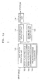
- the video encoding apparatus includes a first motion prediction unit 100, an image information detection unit 110, a second motion prediction unit 120, an encoding unit 130, a first restoration unit 140, a second restoration unit 150, and a deblocking filter unit 160.
- the first motion prediction unit 100 includes an inter-plane predictor 101, an intra-plane predictor 104, and a prediction residue calculator 107.
- An input image (F(n)) 170 is a Y-Cb-Cr image or an R-G-B image.
- the input image 170 is processed per each block by the video encoding apparatus according to the present invention.
- the first motion prediction unit 100 includes an inter-plane predictor 101 which has a motion estimator (ME) 102 and a motion compensator (MC) 103 for estimating and predicting motion on the basis of a previously-restored image (Fr(n-1)) 172 to enhance encoding efficiency, and an intra-plane predictor 104 which has a spatial estimator (SE) 105 and a spatial predictor (SP) 106 for estimating and predicting motion on the basis of spatially adjacent blocks.
- SE spatial estimator
- SP spatial predictor
- the prediction residue calculator 107 obtains an encoded prediction residue image ⁇ F(n) on the basis of the input image 170 and the motion prediction results obtained by the inter-plane predictor 101 or the intra-plane predictor 104. If the input image 170 is a Y-Cb-Cr image, the prediction residue calculator 107 obtains prediction residues ⁇ Y(n), ⁇ U(n) and ⁇ V(n) using the prediction residue image ⁇ F(n). If the input image 170 is an R-G-B image, the prediction residue calculator 107 obtains prediction residues ⁇ R(n), ⁇ G(n) and ⁇ B(n) using the prediction residue image ⁇ F(n).
- the encoding unit 130 performs DCT (or Discrete Integer Transform), quantization and entropy encoding of the prediction residues ⁇ Y(n) ⁇ U(n) and ⁇ V(n) of the Y-Cb-Cr image or the prediction residue ⁇ G(n) of the R-G-B image, thereby compressing the prediction residues.
- DCT Discrete Integer Transform
- a prediction residue predictor (RP) 122 of the second motion prediction unit 120 performs inter-plane prediction of the prediction residues ⁇ B(n) and ⁇ R(n) of R and B components, using a prediction residue ⁇ Gr(n) 124 of a restored G component.
- the first restoration unit 140 obtains restored prediction residue images ⁇ Yr(n), ⁇ Ur(n) and ⁇ Vr(n) if the image to be restored is a Y-Cb-Cr image. Also, the first restoration unit 140 obtains restored prediction residue images ⁇ Gr(n), ⁇ B'r(n) and ⁇ R'r(n) if the image to be restored is an R-G-B image.
- the prediction residue image ⁇ Gr(n) is stored in a buffer 124 so to be subjected to inter-plane prediction by the second motion prediction unit 120.
- the second restoration unit 150 obtains restored prediction residue images ⁇ Br(n) and ⁇ Rr(n) of the R and B components using the restored prediction residue image ⁇ Gr(n) of the G component.
- the restored prediction residue images ⁇ Yr(n) ⁇ Ur(n) and ⁇ Vr(n) of the Y-Cb-Cr image or the restored prediction residue images ⁇ Gr(n) and ⁇ Br(n) of the R-G-B image are input as an input Fr(n) to the deblocking filter 160.
- Gp is a value predicted using a G component image spatially adjacent to the G component or a G component image temporally adjacent to the G component.
- the prediction residue image is actually subjected to entropy encoding.
- values a and b are a gradation and a deviation of the approximated linear function when the prediction residue of the R component is predicted using the prediction residue of the G component
- values c and d are a gradient and a deviation of the approximated linear function when the prediction residue of the B component is predicted using the prediction residue of the G component.
- FIG. 3a is a block diagram showing a structure of a video decoding apparatus according to an embodiment of the present invention.
- the video decoding apparatus includes a first restoration unit 300, an image information detector 310, a second restoration unit 320, a motion prediction unit 330, and a deblocking filter 340.
- the video decoding apparatus restores an image from a compressed bitstream (that is, encoded image).
- the first restoration unit 300 performs entropy decoding 302, dequantization 304, and inverse discrete integer transform 306 of the compressed bitstream (data), and obtains restored prediction residue images ⁇ Yr(n), ⁇ Ur(n) and ⁇ Vr(n) of the respective components of a Y-Cb-Cr image if the compressed bitstream is the Y-Cb-Cr image. Meanwhile, the first restoration unit 300 obtains restored prediction residue images ⁇ Gr(n), ⁇ B'r(n) and ⁇ R'r(n) if the compressed bitstream is an R-G-B image.
- a prediction residue image restored by the first restoration unit 300 is a prediction residue image ⁇ Fr(n) 352 to be input to the motion prediction unit 330.
- the second restoration unit 320 stores a prediction residue image ⁇ Gr(n) of the G component for inter-plane prediction in order to restore prediction residue images of R and B components, if the compressed bitstream is a B or R component (that is, different component other than the reference color component) of the R-G-B image.
- the second restoration unit 320 predicts the first prediction residue image obtained by the first restoration unit 300 using the first prediction residue image of the reference color component, and generates a second prediction residue image, in step S360.
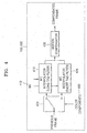
- FIG. 4 is a block diagram showing a structure of a motion compensation apparatus according to an embodiment of the present invention.
- the motion compensation apparatus 103 or 332 includes an image information detector (not shown), a filter tap selector 400, interpolators 410 and 420, and a motion compensator 430.
- the input image interpolated by the interpolator 410 or 420 is subjected to motion compensation by the motion compensator 430.
- the reason of selecting a different tap filter interpolator according to the color component of the input image is because the long tap filter interpolation method using a lot of adjacent pixels can correctly restore the high-frequency components compared to the short tap filter interpolation method, when a lot of high-frequency components exist in the color component of the input image.
- the short tap filter interpolator using the relatively small number of adjacent pixels is more effective in terms of complexity with maintaining similar performance with the long tap filter interpolator, if more low-frequency components exist rather than the high-frequency components in the color component of the input image.
- FIG. 6 is a block diagram showing a structure of a motion compensation apparatus, according to another embodiment of the present invention.
- FIG. 6 is a block diagram of a motion compensation apparatus which uses a different motion compensation method according to color information and resolution information of an image, according to another embodiment of the present invention.
- An image information detector perceives color components and resolution information of an input image.
- the image information detector determines whether the input image is a high-resolution image or a low-resolution image and whether or not the color component of the input image is the reference color component of the R-G-B image.
- the filter tap selector 600 selects the length of a filter tap according to the color information and the resolution information of the input image perceived by the image information detector (not shown). In detail, the filter tap selector 600 selects a short tap filter if the input image is a high-resolution image or if the color component of the input image is a different color component from a Y component (Luma) of a Y-Cb-Cr image. Also, the filter tap selector 600 selects a long tap filter if the input image is a low-resolution image, if the input image is an R-G-B image, or if the color component of the input image is the Y component (Luma) of the Y-Cb-Cr image. Generally, the long tap filter is a 6 tap filter and the short tap filter is a 2 tap filter.
- FIG. 7 is a flowchart illustrating a motion compensation method according to another embodiment of the present invention.
- FIG. 7 is a flowchart illustrating a method performing motion compensation using color components and resolution information.
- the filter tap selector 600 selects the short tap filter interpolator in step S750.
- the reason is because it is unnecessary to use a long tap filter since more low frequency components than high frequency components are included in the high-resolution image.
- the filter tap selector 600 selects the short tap filter interpolator 620 considering complexity.
- the filter tap selector 600 selects the long tap filter interpolator 610 in step 740. If the color component of the input image is a chroma component, the filter tap selector 600 selects the short tap filter interpolator in step S750.
- Clip1(x) means to clip a value x into a predetermined size so that the value x is within a bit range of image pixels.
- the value x of Clip1(x) is set to 0 if x is smaller than 0. If x is greater than 255, x is set to 255 wherein the remaining values are maintained as they are.
- a filter tap used for interpolation is a 6 tap filter (1, -5, 20, 20, -5, 1) which uses a relatively great number of adjacent pixels.
- a pixel j to be located in a 1/2 pixel position is interpolated in a vertical and horizontal direction, using the previously-restored adjacent pixels corresponding to the 1/2 pixel position, according to equations 14a, 14b and 15.
- cc, dd, h1, m1, ee, ff, or aa, bb, b, s1, gg, and hh as adjacent pixel values are intermediate results obtained by performing interpolation by the 6 tap filter as in the above equations 10 and 11.
- the pixel values s and m as final values, which are located in the 1/2 pixel position, are values restored from the pixel values s1 and m1 according to the equations 12 and 13.
- the pixel values a, c, d, n, f, i, k and q, which are located in the 1/4 pixel position, are values obtained by averaging two pixels adjacent in a vertical or horizontal direction, as in the following equations 16 through 23.
- a (G+b+1)>> 1
- c (H+b+1) >> 1
- d (G+h+1) >> 1
- n (M+h+1) >> 1
- FIG. 9 shows an example using a bilinear interpolation method (using a short tap filter) when an image of a previous frame is interpolated four times in a vertical or horizontal direction, in order to compensate for motion.
- This bilinear interpolation method is defined by the MPEG-4 AVC/H.264.
- a ((4- dx ) ⁇ (4- dy ) ⁇ A + dx ⁇ (4- dy ) ⁇ B +(4- dx ) ⁇ dy ⁇ C + dx ⁇ dy ⁇ D +8)>>4
- the bilinear interpolation method uses a relatively small number of adjacent pixels and uses pixel values located near a value to be interpolated, differently from FIG. 7.
- FIG. 10 is a block diagram showing a structure of a deblocking filter unit which uses the characteristics of color components of an image, according to the present invention.
- the characteristics of the color components of an image are used by the deblocking filter unit for reducing block effect generated after image restoration, as well as being used for motion compensation.
- FIG. 10 shows an embodiment of a deblocking filter which considers the color component characteristics of an image.
- Each of the long tap loop filter and short tap loop filter 1010 and 1020 determines whether or not filtering should be performed, on the basis of a block encoding mode, a CBP (Coded Block Pattern), reference image numbers for motion information (MV, MC) of a previous frame, and field information in a case of an interlaced image, and finally removes a block effect of the input image.
- FIG. 11 is a flowchart illustrating a method of selecting a deblocking filter tap according to a color component of an input image, according to an embodiment of the present invention.
- FIG. 12 shows vertical and horizontal directional boundaries to which deblocking filtering is performed in order to reduce a block effect in a 16x16 macro block.
- a macro block is divided into sixteen 4x4 blocks each of which is encoded. Therefore, the block effect is generated at the boundaries of the 4x4 blocks.
- deblocking filtering is performed to vertical boundaries 1201, 1202, 1203, and 1204. Then, as seen in FIG. 12(b), deblocking filtering is performed to horizontal boundaries 1205, 1206, 1207, and 1208.
- FIG. 13 shows coefficients used when the deblocking filtering is performed to the vertical and horizontal boundaries of the 4x4 block.
- p1 p1 + Clip3(-tc, tc, (p2+((p0+p0+1)>>1)-(p1 ⁇ 1)>>1)
- q1 is changed to q'1 if aq is smaller than ⁇ as follows. Otherwise, q1 is not changed.
- q'1 q1 + Clip3(-tc, tc, (q2+((q0+q0+1)>>1)-(q1>>1)
- Tp is 1, p0, p1, and p2 are changed respectively to p'0, p'1, and p'2 by increasing the value of filter coefficients, as follows.
- p'0 (p2+2xp1+2xp0+2xq0+q1+4)>>3
- p'1 (p2+p1+p0+q0+2)>>2
- p'2 (2xp3+3xp2+p1+p0+q0+4)>>3
Abstract
Description
- The present invention relates to a video encoding/decoding apparatus for color images, and more particularly, to an apparatus and method for performing optimal encoding/decoding on the basis of color information and resolution information of color images.
- A conventional video compression method converts an image format such as an R-G-B image into an image format such as a Y-Cb-Cr image suitable to compression, in order to obtain a high compression rate. Also, the conventional video compression method reduces chroma (Cb, Cr) components to 1/4 in their sizes and encodes the Cb and Cr components in order to enhance compression efficiency. However, the conventional video compression method is not suitable to applications requiring high-quality image restoration. This is because energy loss is generated due to subsampling of the Cb and Cr components and the quality loss of the corresponding image is generated when R-G-B components are converted into Y-Cb-Cr components. To reduce these losses, it is necessary to encode the Cb and Cr components with the same resolution as Y components.
- Also, in order to obtain better quality when encoding the Y-Cb-Cr components, it is necessary to reduce the quality loss of the image by directly encoding the R-G-B components. However, the conventional video compression method encodes the R-G-B components using a conventional Y-Cb-Cr encoder, without utilizing characteristics existing in the R-G-B color components different from those of Y-Cb-Cr components. A representative example of such a conventional video compression method is the AVC/H. 264 standard developed by the Joint Video Team of the ISO/IEC MPEG and ITU-T VCEG.
- However, since an R-G-B component and a Y-Cb-Cr component are different in image characteristics, encoding efficiency is very low if the R-G-B component is encoded by the conventional Y-Cb-Cr encoder. For example, the respective components (Y, Cb, and Cr) of a Y-Cb-Cr image have no correlation within a same area, while the respective components (R, G, and B) of an R-G-B image have correlation.
- Also, the R, G and B components of the R-G-B image have a similar frequency characteristic, however, in the Y-Cb-Cr image, the Y component as a Luma component is different in a frequency characteristic from Cb and Cr components as Chroma components due to a process performed when the R-G-B image is converted into the Y-Cb-Cr image. As such, the conventional video compression method has not correctly reflected characteristics of the R-G-B image and the Y-Cb-Cr image to encoding. Also, the conventional video compression method has not considered the change of the frequency characteristic according to the size of an image when encoding.
- According to an aspect of the present invention, there is provided a video encoding apparatus comprising: a first motion prediction unit generating a first prediction residue image for an input image on the basis of a first motion prediction result of the input image; an image information detection unit setting a reference color component among color components of an R-G-B image, determining whether the input image is a Y-Cb-Cr image or the R-G-B image, and determining whether or not a color component of the input image is the reference color component; and a second motion prediction unit performing motion prediction for the first prediction residue image and generating a second prediction residue image, on the basis of the reference color component and creating a second prediction residue image, if the input image is the R-G-B image and if the color component of the input image is not the reference color component.
- The present invention provides a video encoding/decoding apparatus and method for enhancing encoding/decoding efficiency of an R-G-B image using inter-plane prediction.
- According to another aspect of the present invention, there is provided a video encoding method, which is performed by an encoder, comprising: generating a first prediction residue image for an input image on the basis of a first motion prediction result of the input image; setting a reference color component among color components of an R-G-B image, determining whether the input image is a Y-Cb-Cr image or the R-G-B image, and determining whether or not a color component of the input image is the reference color component; and performing motion prediction for the first prediction residue image and generating a second prediction residue image, on the basis of the reference color component, if the input image is the R-G-B image and if the color component of the input image is not the reference color component.
- According to another aspect of the present invention, there is provided a video decoding apparatus comprising: a first restoration unit performing a predetermined operation for an encoded image and generating a first prediction residue image of the encoded image; an image information detection unit determining whether the encoded image is an R-G-B image or a Y-Cb-Cr image and whether or not a color component of the encoded image is a reference color component of the R-G-B image; a second restoration unit generating a second prediction residue image of the encoded image, on the basis of the reference color component, if the encoded image is the R-G-B image and if the color component of the encoded image is not the reference color component; a deblocking filter unit reducing block effect of a decoded image that influences an encoded image restored on the basis of the first prediction residue image and the second prediction residue image.
- The present invention also provides a motion compensation apparatus and method for performing effective motion compensation according to color information and resolution information upon video encoding/decoding.
- According to another aspect of the present invention, there is provided a video decoding method comprising: performing a predetermined operation for an encoded image and generating a first prediction residue image of the encoded image; determining whether the encoded image is an R-G-B image or a Y-Cb-Cr image and whether or not a color component of the encoded image is a reference color component of the R-G-B image; generating a second prediction residue image of the encoded image on the basis of the reference color component if the encoded image is the R-G-B image and if the color component of the encoded image is not the reference color component; and reducing block effect of a decoded image that influences an encoded image restored on the basis of the first prediction residue image and the second prediction residue image.
- According to another aspect of the present invention, there is provided a motion compensation apparatus, which is included in a decoder or encoder, comprising: an image information detector detecting color information of an input image; a filter tap selector selecting a length of a filter tap for compensation on the basis of the color information of the input image; an interpolator interpolating the input image using a filter tap with the selected length; and a motion compensator performing motion compensation for the interpolated result.
- According to another aspect of the present invention, there is provided a motion compensation method, which is performed by an encoder or decoder, comprising: detecting color information of an input image; selecting a length of a filter tap for interpolation on the basis of the color information of the input image; interpolating the input image using a filter tap with the selected length; and performing motion compensation for the interpolated result.
- According to another aspect of the present invention, there is provided a motion compensation apparatus, which is included in a decoder or encoder, comprising: an image information detector detecting resolution and color information of an input image; a filter tap selector selecting a length of a filter tap for interpolation on the basis of the resolution information and the color information of the input image; an interpolator interpolating the input image using a filter tap with the selected length; and a motion compensator performing motion compensation for the interpolated result.
- According to another aspect of the present invention, there is provided a motion compensation method, which is performed by a decoder or encoder, comprising: detecting resolution information and color information of an input image; selecting a length of a filter tap for interpolation on the basis of the resolution information and color information of the input image; interpolating the input image using a filter tap with the selected length; and performing motion compensation for the interpolated result.
- The present invention also provides a deblocking filter for efficiently reducing block efficiency according to color information and resolution information upon video encoding/decoding, and a deblocking filtering method therefor.
- According to another aspect of the present invention, there is provided a deblocking filter apparatus, which is included in a video decoder or video encoder, comprising: an image information detector detecting color information of an image; a deblocking filter selector selecting a length of a deblocking filter tap for reducing block effect of the image on the basis of the color information; a filtering unit filtering the image using a deblocking filter with the selected tap length.
- According to another aspect of the present invention, there is provided a deblocking filter selection method, which is performed by a decoder or encoder, comprising: detecting color information of an image; selecting a length of a deblocking filer for reducing block effect of the image on the basis of the color information; and filtering the image using a deblocking filter with the selected length.
- The above and other features and advantages of the present invention will become more apparent by describing in detail exemplary embodiments thereof with reference to the attached drawings in which:
- FIGS. 1a and 1b are block diagrams showing structures of video encoding apparatuses according to embodiments of the present invention;
- FIG. 2 is a flowchart illustrating a video encoding method according to an embodiment of the present invention;
- FIG. 3a is a block diagram showing a structure of a video decoding apparatus according to an embodiment of the present invention;
- FIG. 3b is a flowchart illustrating a video decoding method according to an embodiment of the present invention;
- FIG. 4 is a block diagram of a motion compensation apparatus for compensating for motion on the basis of color information of an image, according to an embodiment of the present invention;
- FIG. 5 is a flowchart illustrating a method for performing motion compensation according to color information of an image, according to an embodiment of the present invention;
- FIG. 6 is a block diagram of a motion compensation apparatus for compensating for motion on the basis of color information and resolution information of an image, according to another embodiment of the present invention;
- FIG. 7 is a flowchart illustrating a method for compensating motion on the basis of color information and resolution information of an image, according to another embodiment of the present invention;
- FIG. 8 is a view for explaining an interpolation method using a long tab filter;
- FIG. 9 is a view for explaining an interpolation method using a short tab filter;
- FIG. 10 is a view showing a deblocking filter unit;
- FIG. 11 is a flowchart illustrating a method for selecting the deblocking filters according to color information of an image, according to an embodiment of the present invention;
- FIG. 12 shows vertical and horizontal boundaries of macro blocks to be input to the deblocking filter;
- FIG. 13 shows image samples of vertical and horizontal boundaries of a 4x4 block;
- FIG. 14 is a graph showing a simulation result of an inter-plane prediction coding method according to an embodiment of the present invention; and
- FIG. 15 is a graph showing a simulation result when coding is performed using the motion compensation apparatus according to the present invention.
-
- Hereinafter, embodiments of the present invention will be described in detail with reference to the appended drawings. The same reference numbers refer to the same components throughout the drawings.
- FIG. 1a is a block diagram showing a structure of a video encoding apparatus according to an embodiment of the present invention.
- Referring to FIG. 1a, the video encoding apparatus according to an embodiment of the present invention includes a first
motion prediction unit 100, an imageinformation detection unit 110, a secondmotion prediction unit 120, and anencoding unit 130. The firstmotion prediction unit 100 includes aninter-plane predictor 102, anintra-plane predictor 104, and aprediction residue calculator 106. - The
inter-plane predictor 102 andintra-plane predictor 104 of the firstmotion prediction unit 100 perform motion prediction of an input image on the basis of temporally and spatially adjacent images of the input image. Theinter-plane predictor 102 performs motion prediction of the input image using a previously-restored image temporally adjacent to the input image. Theintra-plane predictor 104 performs motion prediction of the input image using encoding unit blocks of an input image spatially adjacent to the input image. Generally, since an initial input image has no previously-restored image, theintra-plane predictor 104 performs motion prediction for the initial input image and theinter-plane predictor 102 performs motion prediction for the following input images. Theprediction residue calculator 106 generates a first prediction residue image using a difference between the input image and a motion prediction result of theinter-plane predictor 102 or theintra-plane predictor 104. - Also, the first
motion prediction unit 100 selectively uses filter taps with different tap lengths according to color information and resolution information of the input image. This will be described in detail later with reference to FIGS. 4 through 9. - The image
information detection unit 110 determines whether the input image is a Y-Cb-Cr image or an R-G-B image. Also, the imageinformation detection unit 110 perceives a color component of the input image. That is, the imageinformation detection unit 110 determines whether the color component of the input image is an R, G, or B component of an R-G-B image, or a Y (Luma), Cb, or Cr (Chroma) component of a Y-Cb-Cr image. Also, the imageinformation detection unit 110 sets a specific color component among color components of the R-G-B image to a reference color component. That is, one among the R, G and B components can be set to the reference color component. Hereinafter, it is assumed that the G component is set to the reference color component. - The second
motion prediction unit 120 performs motion prediction for the first prediction residue image output from the firstmotion prediction unit 100 on the basis of the reference color component if a color component of an input image is the reference color component of the R-G-B image, and generates a second prediction residue image. The reference color component used by thesecond prediction unit 120 is received, encoded and decoded before a current input image is received. In detail, the secondmotion prediction unit 120 performs motion prediction on the basis of a prediction residue image of the reference color component encoded and decoded. - For example, if the reference color component is a G component and a color component of an input image is a B component, the first
motion prediction unit 100 generates a first prediction residue for the B and G components on the basis of a motion prediction result of the input image. Also, the imageinformation detection unit 110 determines whether the input image is an R-G-B image and whether the color component of the input image is a different color component (for example, B component) from the reference color component (G component). The secondmotion prediction unit 120 performs inter-plane prediction for the first prediction residue image of the input image (B component) on the basis of a first encoded prediction residue image of the reference color component (G component) encoded and then decoded, and generates a second prediction residue image. That is, the input image with the B component is subjected to prediction twice by the firstmotion prediction unit 100 and the secondmotion prediction unit 120. - The
encoding unit 130 encodes the first prediction residue image generated by the firstmotion prediction unit 100 and the second prediction residue image generated by the secondmotion prediction unit 120, and generates a bitstream. In detail, theencoder 130 performs Discrete Cosine Transform (DCT) orDiscrete Integer Transform 132 of the prediction residue images, performs quantization and entropy-encoding of the transformed values, and generates an encoded image (bitstream). - Since a Y-Cb-Cr image is converted from an R-G-b image using a color coordinate transform method, the Y-Cb-Cr image and the R-G-B image have different characteristics in terms of encoding. That is, the respective Y, Cb, and Cr components of the Y-Cb-Cr image do not have correlation to each other at the same spatial location, while the respective components of the R-G-B image have correlation to each other. Accordingly, the video encoding apparatus according to the present invention uses a different prediction method when encoding, according to whether an input image is an R-G-B image or a Y-Cb-Cr image.
- As a result, the video encoding apparatus according to the present invention sets one of color components of an R-G-B image to a reference color component and encodes the reference color component using the conventional encoding method. Also, the video encoding apparatus predicts the remaining two color components except for the reference color component of the R-G-B image, using spatially adjacent pixels or temporally adjacent pixels, and then performs prediction of the predicted result once more on the basis of the reference color component.
- FIG. 1 b is a block diagram showing a structure of a video encoding apparatus according to another embodiment of the present invention.
- Referring to FIG. 1 b, the video encoding apparatus according to the present invention includes a first
motion prediction unit 100, an imageinformation detection unit 110, a secondmotion prediction unit 120, anencoding unit 130, afirst restoration unit 140, asecond restoration unit 150, and adeblocking filter unit 160. The firstmotion prediction unit 100 includes aninter-plane predictor 101, anintra-plane predictor 104, and aprediction residue calculator 107. - An input image (F(n)) 170 is a Y-Cb-Cr image or an R-G-B image. The
input image 170 is processed per each block by the video encoding apparatus according to the present invention. The firstmotion prediction unit 100 includes aninter-plane predictor 101 which has a motion estimator (ME) 102 and a motion compensator (MC) 103 for estimating and predicting motion on the basis of a previously-restored image (Fr(n-1)) 172 to enhance encoding efficiency, and anintra-plane predictor 104 which has a spatial estimator (SE) 105 and a spatial predictor (SP) 106 for estimating and predicting motion on the basis of spatially adjacent blocks. - An interpolation method for motion compensation is changed according to the respective color components of Y-Cb-Cr (or Y-U-V) images and R-G-B images. First, the
prediction residue calculator 107 obtains an encoded prediction residue image Δ F(n) on the basis of theinput image 170 and the motion prediction results obtained by theinter-plane predictor 101 or theintra-plane predictor 104. If theinput image 170 is a Y-Cb-Cr image, theprediction residue calculator 107 obtains prediction residues Δ Y(n), Δ U(n) and Δ V(n) using the prediction residue image Δ F(n). If theinput image 170 is an R-G-B image, theprediction residue calculator 107 obtains prediction residues Δ R(n), Δ G(n) and Δ B(n) using the prediction residue image Δ F(n). - The
encoding unit 130 performs DCT (or Discrete Integer Transform), quantization and entropy encoding of the prediction residues Δ Y(n) Δ U(n) and Δ V(n) of the Y-Cb-Cr image or the prediction residue Δ G(n) of the R-G-B image, thereby compressing the prediction residues. - If the
input image 170 is an R-G-B image, a prediction residue predictor (RP) 122 of the secondmotion prediction unit 120 performs inter-plane prediction of the prediction residues Δ B(n) and Δ R(n) of R and B components, using a prediction residue Δ Gr(n) 124 of a restored G component. - Also, the
encoding unit 130 performs DCT (or Discrete Integer Transform), quantization, and entropy encoding of prediction residue images Δ B' and Δ R'(n) obtained through the inter-plane prediction, thereby compressing the prediction residue images. The DCT is defined by the ISO/IEC MPEG-4 part 2 standard and the Discrete Integer Transform is defined by the AVC/H. 264 standard developed by the Joint Video Team of the ISO/IEC MPEG and ITU-T VCEG. - The
first restoration unit 140 performs dequantization of the image (to be restored) transformed and quantized by theencoding unit 130 so that the image can be used for prediction using spatially adjacent blocks or temporally following images, and then performs Inverse Discrete Cosine Transform (IDCT) of the image, thereby generating prediction residue images for the respective color components of the image. - The
first restoration unit 140 obtains restored prediction residue images Δ Yr(n), Δ Ur(n) and Δ Vr(n) if the image to be restored is a Y-Cb-Cr image. Also, thefirst restoration unit 140 obtains restored prediction residue images Δ Gr(n), Δ B'r(n) and Δ R'r(n) if the image to be restored is an R-G-B image. The prediction residue image Δ Gr(n) is stored in abuffer 124 so to be subjected to inter-plane prediction by the secondmotion prediction unit 120. - If color components of the image to be restored are R and B components, the
second restoration unit 150 obtains restored prediction residue images Δ Br(n) and Δ Rr(n) of the R and B components using the restored prediction residue image Δ Gr(n) of the G component. The restored prediction residue images Δ Yr(n) Δ Ur(n) and Δ Vr(n) of the Y-Cb-Cr image or the restored prediction residue images Δ Gr(n) and Δ Br(n) of the R-G-B image are input as an input Fr(n) to thedeblocking filter 160. - The deblocking filter (loop filter)
unit 160 adds the input Fr(n) to the inter-plane or intra-plane prediction results generated by the firstmotion prediction unit 100, and filters the added result, thereby reducing a block effect. Thedeblocking filter unit 160 according to the present invention uses different filter tap lengths at block boundary areas according to the respective components of the Y-Cb-Cr (or Y-U-V) image and the R-G-B image. This will be described in detail with reference to FIGS. 10 and 11. - FIG. 2 is a flowchart illustrating a video encoding method according to an embodiment of the present invention.
- Referring to FIGS. 1 a and 2, the first
motion prediction unit 100 performs temporal/spatial prediction (inter-plane prediction/intra-plane prediction) for an input image, in step S200. The imageinformation detection unit 110 sets a G component as a reference color component of an R-G-B image and determines whether or not the input image is an R-G-B image, in step S210. If the input image is an R-G-B image, the imageinformation detection unit 110 determines whether the color component of the input image is the G component being the reference color component, in step S220. If the color component of the input image is an R or B component, the secondmotion prediction unit 120 performs inter-plane prediction on the respective components using a prediction residue image of a restored G component in step S306. In other words, the video encoding method according to the present invention performs motion prediction for different color components except for the reference color component, using the firstmotion prediction unit 100, and then performs motion prediction for the difference color components on the basis of the reference color component. The prediction residue images obtained by the firstmotion prediction unit 100 or the secondmotion prediction unit 110 are compressed by DCT (or Discrete Integer Transform), quantization, and entropy encoding. - Hereinafter, the intra-plane prediction applied to the R and B components except for the reference color component of the R-G-B image will be described in more detail. First, motion prediction is performed on an input image with a G component using the input image and a prediction residue image Δ G of the G component is obtained from the difference between the result of the motion prediction and the input image. This prediction residue image Δ G can be expressed by
equation 1. - Here, Gp is a value predicted using a G component image spatially adjacent to the G component or a G component image temporally adjacent to the G component. The prediction residue image is actually subjected to entropy encoding.
- A correlation between the G, R, and B components is still great, compared to the Y, Cr, and Cb components. In order to use similarity between the G component and the R and B components, the R and B components are temporally and spatially predicted as the G component is. Accordingly, prediction residue images Δ R and Δ G are obtained as follows.
- Here, Rp and Bp are prediction residue values of the R and B components predicted using their spatially or temporally adjacent images. The prediction residue values are subtracted by a linearly-transformed value of an encoded and decoded prediction residue image of the G component, so that inter-plane predicted residue images Δ R' and Δ G' of the R and B components are obtained as in the following
equations 4 and 5. - These values are smaller in a data amount to be encoded compared to the temporal/spatial prediction residues Δ R and Δ B of the R and B components, so that encoding efficiency can be enhanced. This is because the prediction residue images Δ R and Δ B can be approximated to a function of Δ G by expressing a relationship between the prediction residues Δ G and Δ R and a relationship between the prediction residues Δ G and Δ B by a linear function using a fact that the correlation between the prediction residue images Δ G, Δ R, and Δ B is great. Hereinafter, values a and b (equations 6 and 7) are a gradation and a deviation of the approximated linear function when the prediction residue of the R component is predicted using the prediction residue of the G component, and values c and d (equation 8 and 9) are a gradient and a deviation of the approximated linear function when the prediction residue of the B component is predicted using the prediction residue of the G component.
- Here, cov(· ) is a covariance, E(· ) is an average of the values, and σ 2 is a variance.
- FIG. 3a is a block diagram showing a structure of a video decoding apparatus according to an embodiment of the present invention.
- Referring to FIG. 3a, the video decoding apparatus according to an embodiment of the present invention includes a
first restoration unit 300, animage information detector 310, asecond restoration unit 320, amotion prediction unit 330, and adeblocking filter 340. - The video decoding apparatus according to the present invention restores an image from a compressed bitstream (that is, encoded image). The
first restoration unit 300 performsentropy decoding 302,dequantization 304, and inverse discrete integer transform 306 of the compressed bitstream (data), and obtains restored prediction residue images Δ Yr(n), Δ Ur(n) and Δ Vr(n) of the respective components of a Y-Cb-Cr image if the compressed bitstream is the Y-Cb-Cr image. Meanwhile, thefirst restoration unit 300 obtains restored prediction residue images Δ Gr(n), Δ B'r(n) and Δ R'r(n) if the compressed bitstream is an R-G-B image. - The
image information detector 310 determines whether the compressed bitstream is a Y-Cb-Cr image or an R-G-B image, and whether a color component of the compressed bitstream is a reference color component of an R-G-B image. Hereinafter, it is assumed that a G component is set to the reference color component. - If the compressed bitstream is a Y-Cb-Cr image or a reference color component of an R-G-B image, a prediction residue image restored by the
first restoration unit 300 is a prediction residue image Δ Fr(n) 352 to be input to themotion prediction unit 330. - The
second restoration unit 320 stores a prediction residue image Δ Gr(n) of the G component for inter-plane prediction in order to restore prediction residue images of R and B components, if the compressed bitstream is a B or R component (that is, different component other than the reference color component) of the R-G-B image. - Meanwhile, if a bitsteam is encoded by the inter-plane prediction of the video encoder (FIGS. 1 a and 1b), the
second restoration unit 320 adds an inter-plane predicted value of a previous image Fr(n-1) obtained by a MC (motion comparator) 332 of themotion prediction unit 330 with a prediction residue image obtained by thefirst restoration unit 300 and thesecond restoration unit 320, and obtains restored values of the respective components of the R-G-B or Y-Cb-Cr image. If the bitstream is encoded by the intra-plane prediction, thesecond restoration unit 320 adds intra-plane prediction values obtained by a SP (spatial predictor) 334 of themotion predictor 330 with a prediction residue image obtained by thefirst restoration unit 330 and thesecond restoration unit 320, and obtains restored values of the respective components of the R-G-B or Y-Cb-Cr image. Here, the inter-plane prediction of themotion prediction unit 330 is performed using different interpolation methods upon motion compensation, according to the respective components of the Y-Cb-Cr (or, Y-U-V) image and the R-G-B image. This will be described in more detail with reference to FIGS. 4 through 9. The values restored by thesecond restoration unit 320 are passed through thedeblocking filter 340 for reducing a block effect and are output as restored images Fr(n) 352 of the respective color components. - The
deblocking filter unit 340 selectively uses deblocking filter with different filter tap lengths, which are used at block boundaries, according to the respective components of the Y-Cb-Cr (or, Y-U-V) image and the R-G-B image. This will be described with reference to FIGS. 10 and 11. - FIG. 3b is a flowchart illustrating a video decoding method according to an embodiment of the present invention.
- Referring to FIGS. 3a and 3b, the
first restoration unit 300 generates a first prediction residue image from the bitstream in step S350. Also, theimage information detector 310 determines whether the bitstream is a Y-Cb-Cr image or an R-G-B image and whether a color component of the bitstream is a reference color component of the R-G-B image, in step S355. - If the bitstream is an R-G-B image and the color component of the bitstream is not a reference color component of the R-G-B image, the
second restoration unit 320 predicts the first prediction residue image obtained by thefirst restoration unit 300 using the first prediction residue image of the reference color component, and generates a second prediction residue image, in step S360. - The
second restoration unit 320 adds the first and second prediction residue images with the motion prediction result for the previous image obtained by themotion predictor 330, and obtains a restored image, in step S365. Thedeblocking filter unit 340 reduces a block effiect of the restored image and obtains a final restored image Fr(n) 352 in step S370. - FIG. 4 is a block diagram showing a structure of a motion compensation apparatus according to an embodiment of the present invention.
- Referring to FIG. 4, the
motion compensation apparatus filter tap selector 400,interpolators motion compensator 430. - R, G, and B components of an R-G-B image have a similar frequency characteristic, but in a Y-Cb-Cr image, a Y component as a Luma component is different in a frequency characteristic from Cb and Cr components as Chroma components. Also, the chroma components of the Y-Cb-Cr image have a lot of low frequency components and great correlation therebetween, compared to the Luma component. FIG. 4 is a block diagram of a motion compensation apparatus using a different prediction method according to color components of an image.
- The image information detector (not shown) determines whether an input image is a Y-Cb-Cr image or an R-G-B image and whether a color component of the input image is a reference color component of an R-G-B image. Generally, the reference color component of the R-G-B image is set to a G component.
- The
filter tap selector 400 selects a longtap filter interpolator 410 or a shorttap filter interpolator 420 according tocolor component information 402 of an input image received from the image information detector (not shown). That is, thefilter tap selector 400 selects a filter tap for optimal motion prediction according to the respective color components of the input image. In this disclosure, a long tap filter may be a 6 tap filter and a short tap filter may be a 2 tap filter. - For example, the
filter tap selector 400 selects a 6 tap filter interpolator if the input image is the Y-Cb-Cr image or if the color component of the input image is not the reference color component of the R-G-B image, and selects a 2 tap filter interpolator if the color component of the input image is the reference color component of the R-G-B image. - The
interpolator filter tap selector 400 interpolates the input image to perform motion compensation of the input image. At this time, each of theinterpolators motion vector 412 of a previous frame. - Alternately, the
interpolators tap filter interpolator 410 and abilinear interpolator 420, respectively. If thefilter tap selector 400 selects the 6tap filter interpolator 410, the 6tap filter interpolator 410 interpolates the input image. - The input image interpolated by the
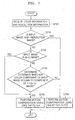
interpolator motion compensator 430. - FIG. 5 is a flowchart illustrating a method for performing motion compensation according to a color component of the input image, according to the present invention.
- Referring to FIGS. 4 and 5, the
filter tap selector 400 selects a filter tap based on a color component received from the image information detector (not shown), in step S500. If it is determined instep S51 0 that the color component of the input image is an R-G-B component, thefilter tap selector 400 selects the same interpolation method for the respective component of he R-G-B image in step S520. For example, thefilter tap selector 400 allows all the respective components of the R-G-B image to be passed through the longtap filter interpolator 410 or allows all the respective components of the R-G-B image to be passed through the shorttap filter interpolator 420. - If it is determined that the color component of the input image is not an R-G-B component and is a Y-Cb-Cr component, the image information detector (not shown) determines whether the color component of the input image is a Y component (Luma) in step S530. If the color component of the input image is the Luma component, the
filter tap selector 400 selects the longtap filter interpolator 410 so that the input image can be interpolated by the longtap filter interpolator 410 in step S540. If the color component of the input image is a chroma component (Cb, Cr), thefilter tab selector 400 selects the shorttap filter interpolator 420 in step S550. - The reason of selecting a different tap filter interpolator according to the color component of the input image is because the long tap filter interpolation method using a lot of adjacent pixels can correctly restore the high-frequency components compared to the short tap filter interpolation method, when a lot of high-frequency components exist in the color component of the input image. On the contrary, the short tap filter interpolator using the relatively small number of adjacent pixels is more effective in terms of complexity with maintaining similar performance with the long tap filter interpolator, if more low-frequency components exist rather than the high-frequency components in the color component of the input image.
- FIG. 6 is a block diagram showing a structure of a motion compensation apparatus, according to another embodiment of the present invention.
- Referring to FIG. 6, the
motion compensation apparatus filter tap selector 600,interpolators motion compensator 630. - Size or
resolution information 604 of an image as well as thecolor component 602 of the image influences the frequency characteristic. FIG. 6 is a block diagram of a motion compensation apparatus which uses a different motion compensation method according to color information and resolution information of an image, according to another embodiment of the present invention. - An image information detector (not shown) perceives color components and resolution information of an input image. In detail, the image information detector (not shown) determines whether the input image is a high-resolution image or a low-resolution image and whether or not the color component of the input image is the reference color component of the R-G-B image.
- The
filter tap selector 600 selects the length of a filter tap according to the color information and the resolution information of the input image perceived by the image information detector (not shown). In detail, thefilter tap selector 600 selects a short tap filter if the input image is a high-resolution image or if the color component of the input image is a different color component from a Y component (Luma) of a Y-Cb-Cr image. Also, thefilter tap selector 600 selects a long tap filter if the input image is a low-resolution image, if the input image is an R-G-B image, or if the color component of the input image is the Y component (Luma) of the Y-Cb-Cr image. Generally, the long tap filter is a 6 tap filter and the short tap filter is a 2 tap filter. - There are an interpolator 610 (also, referred to as a long tap filter interpolator) using a long filter tap and an interpolator 620 (also, referred to as a short tap filter interpolator) using a short filter tap, and the
interpolators - The
motion compensator 630 compensates for motion of the input image interpolated by the interpolators. - FIG. 7 is a flowchart illustrating a motion compensation method according to another embodiment of the present invention. In detail, FIG. 7 is a flowchart illustrating a method performing motion compensation using color components and resolution information.
- Referring to FIGS. 6 and 7, the image information detector (not shown) receives image size information of an input image in step S700 and determines whether the input image is a high-resolution image in step S710. In the present invention, the high-resolution image means an image with a size greater than an image size of 1280 x 720 being the HD resolution level. A reference image size of 1280 x 720 can be changed according to environments and applications.
- If the input image is a high-resolution image, the
filter tap selector 600 selects the short tap filter interpolator in step S750. The reason is because it is unnecessary to use a long tap filter since more low frequency components than high frequency components are included in the high-resolution image. In the case of the high-resolution image, since a small portion of an actual image is displayed by a great number of pixels, differences between pixel values are small. In this case, since a video quality difference between when the long tap filter is used and when the short tap filter is used is small, thefilter tap selector 600 selects the shorttap filter interpolator 620 considering complexity. - If the input image is a low-resolution image, the image information detector (not shown) receives color information in step S700 and determines whether the input image is an R-G-B image in step S720. If the color component of the input image is a R, G, or B component in step S730, the
filter tap selector 600 selects the longtap filter interpolator 610 so that all the respective components of the input image can be interpolated by the longtap filter interpolator 610. If the color component of the input image is not the R, G, or B component and is a Y, Cb, or Cr component, the image information detector (not shown) determines whether the color component of the input image is a Y component (Luma) in step S730. If the color component of the input image is the Luma component, thefilter tap selector 600 selects the longtap filter interpolator 610 in step 740. If the color component of the input image is a chroma component, thefilter tap selector 600 selects the short tap filter interpolator in step S750. - FIG. 8 shows an example in which the 6 tap filter is used when an image of a previous frame is interpolated four times in a vertical or a horizontal direction for motion compensation.
- The 6 tap filter is defined by the MPEG-4 AVC/H.264. Referring to FIG. 8, when pixels A through U of a previous frame are given, pixels a through s, which are located in a 1/4 or 1/2 pixel position, can be obtained according to the following equations.
- First, pixels b and h to be located in the 1/2 pixel position, which is located in a vertical or horizontal direction from corresponding pixels, are interpolated using 6 adjacent pixels as follows.
- Here, Clip1(x) means to clip a value x into a predetermined size so that the value x is within a bit range of image pixels. In the case where an input image is a 8-bit image, the value x of Clip1(x) is set to 0 if x is smaller than 0. If x is greater than 255, x is set to 255 wherein the remaining values are maintained as they are. A filter tap used for interpolation is a 6 tap filter (1, -5, 20, 20, -5, 1) which uses a relatively great number of adjacent pixels.
- A pixel j to be located in a 1/2 pixel position is interpolated in a vertical and horizontal direction, using the previously-restored adjacent pixels corresponding to the 1/2 pixel position, according to equations 14a, 14b and 15.
- Here, cc, dd, h1, m1, ee, ff, or aa, bb, b, s1, gg, and hh as adjacent pixel values are intermediate results obtained by performing interpolation by the 6 tap filter as in the above equations 10 and 11.
- The pixel values s and m as final values, which are located in the 1/2 pixel position, are values restored from the pixel values s1 and m1 according to the equations 12 and 13.
- The pixel values a, c, d, n, f, i, k and q, which are located in the 1/4 pixel position, are values obtained by averaging two pixels adjacent in a vertical or horizontal direction, as in the following equations 16 through 23.
- The pixel values e, g, p, and r, which are located in the 1/4 pixel position, are value obtained by averaging two pixels adjacent in a diagonal direction, as in equations 24 through 27.
- FIG. 9 shows an example using a bilinear interpolation method (using a short tap filter) when an image of a previous frame is interpolated four times in a vertical or horizontal direction, in order to compensate for motion. This bilinear interpolation method is defined by the MPEG-4 AVC/H.264.
- In the pixels A, B, C, and D of the previous frame, a pixel value which is located in a 1/4 or 1/2 pixel position can be obtained by equation 28a.
- Here, dx is a value representing, with a 1/4 pixel position, a distance by which the pixel a is separated in a horizontal direction from the pixel A or C, and dy is a value representing, with a 1/4 pixel position, a distance by which the pixel a is separated in a vertical direction from the pixel A or B.
- Referring to FIG. 9, the bilinear interpolation method uses a relatively small number of adjacent pixels and uses pixel values located near a value to be interpolated, differently from FIG. 7.
- FIG. 10 is a block diagram showing a structure of a deblocking filter unit which uses the characteristics of color components of an image, according to the present invention. The characteristics of the color components of an image are used by the deblocking filter unit for reducing block effect generated after image restoration, as well as being used for motion compensation. FIG. 10 shows an embodiment of a deblocking filter which considers the color component characteristics of an image.
- Referring to FIG. 10, a
deblocking filter unit deblocking filter selector 1000, a long tap loop (deblocking)filter 1010, and a short tap loop (deblocking)filter 1020. - The image information detector (not shown) determines whether an input image is a Y-Cb-Cr image or an R-G-B image and whether a color component of the input image is a luma (Y) component.
- The
deblocking filter selector 1000 selects one of the long tap loop filter and shorttap loop filter deblocking filter selector 1000 selects the longtap loop filter 1010 if the input image is the R-G-B image or if the color component of the input image is the luma (Y) component of the Y-Gb-Gr image. Also, thedeblocking filter selector 1000 selects the shorttap loop filter 1020 if the color component of the input image is a chroma (Cb or Cr) component of the Y-Cb-Cr image. - The long
tap loop filter 1010 has a different filter tap length from that of the shorttap loop filter 1020. One of the longtap loop filter 1010 and the shorttap loop filter 1020 is selected by thedeblocking filter selector 1000. - Each of the long tap loop filter and short
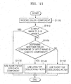
tap loop filter - FIG. 11 is a flowchart illustrating a method of selecting a deblocking filter tap according to a color component of an input image, according to an embodiment of the present invention.
- Referring to FIGS. 10 and 11, the
deblocking filter selector 1000 receives color information from the image information detector (not shown), and determines whether a color component of the input image is a color component of an R-G-B image in step S1110. If the color component of the input image is the color component of the R-G-B image, thedeblocking filter selector 1000 allocates the same filter tap coefficient to each of the color components instep 1130. In this case, thedeblocking filter selector 1000 generally selects the longtap loop filter 1010. If the color component of the input image is a color component of the Y-Cb-Cr image, thefilter tap selector 1000 selects thelong tap filter 1010 in step S1140. If the color component of the input image is a chroma component, thefilter tap selector 1000 selects the shorttap loop filter 1020 in step S1150. - FIG. 12 shows vertical and horizontal directional boundaries to which deblocking filtering is performed in order to reduce a block effect in a 16x16 macro block.
- Referring to FIG. 12, a macro block is divided into sixteen 4x4 blocks each of which is encoded. Therefore, the block effect is generated at the boundaries of the 4x4 blocks. As shown in FIG. 12(a), first, deblocking filtering is performed to
vertical boundaries horizontal boundaries - FIG. 13 shows coefficients used when the deblocking filtering is performed to the vertical and horizontal boundaries of the 4x4 block.
- In the vertical boundaries, as shown in FIG. 13(a), to reduce a block effect using pixel values of pixels p0, p1, p2, p3, q0; q1, q2, and q3 and a filter tap, the pixel values of the pixels p0, p1, p2, q0, q1, q2 are changed. FIG. 13(b) shows pixels to whose horizontal boundaries deblocking filtering is performed.
- Since a loss level is different for each 4x4 block, it is necessary to change filter coefficients and determine whether or not filtering should be performed, for each 4x4 block. For that, as shown in FIG. 10, whether or not deblocking filtering should be performed, that is, the length of filter tap, etc. are decided using a predetermined threshold value, on the basis of a block encoding mode, a CBP (Coded Block Pattern), reference image numbers for motion information (MV, MC) of a previous frame, and field information in a case of an interlaced image. As a basic filter method, a filtering method defined by the MPEG-4 AVC/H.264 is used. A value filterFlag for deciding whether or not filtering should be performed to a 4x4 block can be calculated by equation 28b.
- Here, deblocking filtering is performed only when the value filterFlag is 1. α and β are threshold values for deciding whether or not the deblocking filtering should be performed according to a change of adjacent pixel values. The threshold values α and β become greater as a quantization value increase. Bs (filter strength) is a value indicating a range of pixel values to be changed through the filter when the deblocking filtering is performed. The value Bs has a value between 0 through 4. If the value Bs is 0, filtering is not performed. As the value Bs approaches 4, the value of filter coefficients becomes greater. The value Bs is changed so that a majority of pixels among the pixels p0, p1, p2, p3, q0, q1, q2, q3 reduce a block effect.
- First, long tap filter coefficients used when the color component is a R, G, and B component or a Y component of a Y-Cb-Cr image, can be defined by equations 29 through 45.
- If the value Bs is smaller than 4, the pixels p0 and q0 most adjacent to the boundary are changed to p'0 and q'0 as follows.
- Here, Clip3(min, max, x) is defined to locate a value x between a minimum value min and a maximum value max. Clip1(x) has the same meaning as Clip1(x) of equation 12. tc is a threshold value for limiting a pixel value. Here, if the value Bs is great, tc also has a great value, which makes a changing level of a pixel value greater.
- In the case of p1 and q1, the following values are defined in order to decide whether or not filtering should be performed.
- Here, if ap is smaller than β, p1 is changed to p'1. Otherwise, p1 is not changed.
- Here, q1 is changed to q'1 if aq is smaller than β as follows. Otherwise, q1 is not changed.
- If Bs is 4, values Tp and Tq for deciding filter coefficients are defined as follows.
- If Tp is 1, p0, p1, and p2 are changed respectively to p'0, p'1, and p'2 by increasing the value of filter coefficients, as follows.
- Meanwhile, if Tp is 0, only p0 is changed to p'0 by decreasing the value of the filter coefficients.
- Meanwhile, if Tq is 1, q0, q1, and q2 are changed respectively to q'0, q'1, and q'2 by increasing the value of the filter coefficients as follows.
- Meanwhile, if Tq is 0, only q0 is changed to q'0 by decreasing the value of filter coefficients as follows.
- If the color component of the Y-Cb-Cr image is a Cb or Cr component, the short tap filter coefficients are defined as follows. First, if Bs is smaller than 4, p0 and q0 are changed to p'0 and q'0, respectively, according to
equations 30 and 31. Differently from the R-G-B image and the Y component, the values of p1 and q1 are not changed. If Bs is 4, only the values of p0 and q0 are changed to p'0 and q'0, respectively, according toequations 41 and 45. Differently from the R-G-B image and the Y component, the values of p1 and q1 are not changed. - FIG. 14 is a graph showing a simulation result of video encoding using an inter-plane prediction coding method according to an embodiment of the present invention, when an R-G-B image is provided as an input image. FIG. 14 shows a comparison result of when the inter-plane prediction according to the present invention is used and when the inter-plane prediction is not used.
- Here, an input image is a CREW image with a 1280 x 720 size, the simulation result is represented with PSNR at four bit rates.
- FIG. 14a shows a simulation result in an intra mode that performs only spatial prediction, and FIG. 14b shows a simulation result when all of temporal prediction and spatial prediction are used. As shown in FIG. 14, there is more than 3 dB gain difference between the present invention and the conventional technique at a same bit rate.
- FIG. 15a shows a comparison result for a 640 x 350 Harbour image, between a case (MC_LL) where a 6 tap filter is used for motion compensation and a case (MC_LC) where the 6 tap filter is used for G components and the bilinear filter is used for R and B components, when an R-G-B image is used as an input image
- It is seen in FIG. 15a that in the MC_LL method according to the present invention, a PSNR gain is higher than that of the conventional technique at a same bit rate.
- FIG. 15b shows a comparison result for a 640 x 352 Harbour image, between a case (MC_LC) where the 6 tap filter is used for Y components and the Bilinear filter is used for Cb and Cr components and a case (MC_LL) where the 6 tap filter is used for all of Y, Cb and Cr components for motion compensation, when a Y-Cb-Cr image is used as an input image. It is seen in FIG. 15b that in the present invention, PSNR is improved at a same bit rate for each Y, Cb, and Cr component.
- The present invention may be embodied as a program stored on a computer readable medium that can be run on a general computer. Here, the computer readable medium includes but is not limited to storage media such as magnetic storage media (e.g., ROM's, floppy disks, hard disks, etc.), optically readable media (e.g., CD-ROMs, DVDs, etc.), and carrier waves (e.g., transmission over the Internet). The present invention may also be embodied as a computer readable program code unit stored on a computer readable medium, for causing a number of computer systems connected via a network to affect distributed processing.
- As described above, the present invention can efficiently encode and decode video data considering color component characteristics of an input image. In particular, it is possible to improve encoding efficiency of an R-G-B image through inter-plane prediction. The present invention can be applied to Digital Archive, digital cinema, etc. requiring image information with high-quality since R-G-B images are directly encoded.
- Also, the present invention utilizes all of color component characteristics and image resolution characteristics for motion compensation and deblocking filtering in an encoder and decoder. The present invention can improve encoding efficiency by enhancing image quality through filtering according to characteristics of images. Therefore, the present invention can construct a suitable encoder and decoder in correspondence to respective characteristics of R-G-B images and Y-Cb-Cr images.
- While the present invention has been particularly shown and described with reference to exemplary embodiments thereof, it will be understood by those of ordinary skill in the art that various changes in form and details may be made therein without departing from the scope of the present invention as defined by the following claims.
Claims (43)
- A video encoding apparatus comprising:a first motion prediction unit generating a first prediction residue image for an input image on the basis of a first motion prediction result of the input image;an image information detection unit setting a reference color component among color components of an R-G-B image, determining whether the input image is a Y-Cb-Cr image or the R-G-B image, and determining whether or not a color component of the input image is the reference color component; anda second motion prediction unit performing motion prediction for the first prediction residue image and generating a second prediction residue image, on the basis of the reference color component and creating a second prediction residue image, if the input image is the R-G-B image and if the color component of the input image is not the reference color component.
- The video encoding apparatus of claim 1, further comprising an encoding unit for encoding the first prediction residue image and the second prediction residue image.
- The video encoding apparatus of claim 2, wherein the encoding unit performs discrete cosine transform or discrete integer transform, quantization, and entropy encoding for the first prediction residue image and the second prediction residue image.
- The video encoding apparatus of any preceding claim, wherein a reference color component of the R-G-B image is a G component.
- The video encoding apparatus of any preceding claim, wherein the second motion prediction unit performs motion prediction for the first prediction residue image of the input image and generates the second prediction residue image, on the basis of an encoded and decoded first prediction residue image of the reference color component.
- The video encoding apparatus of claim 5, wherein the second motion prediction unit generates the second prediction residue image on the basis of a difference between a linearly-transformed value of the first prediction residue image of the reference color component and the first prediction residue image of the input image.
- The video encoding apparatus of any one of claims 1, 5, and 6, wherein the reference color component is received, encoded and decoded before the input image is received.
- The video encoding apparatus of any preceding claim, wherein the first motion prediction unit comprises:an inter-plane predictor predicting motion of the input image using a previously-restored image which is temporally adjacent to the input image;an intra-plane predictor predicting motion of the input image using an encoding unit block which is spatially adjacent to the input image; anda prediction residue calculator selecting an prediction result of the inter-plane predictor or an prediction result of the intra-plane predictor and generating the first prediction residue image on the basis of a difference between the selected prediction result and the input image.
- The video encoding apparatus of claim 8, wherein the prediction residue calculator selects the prediction result of the intra-plane predictor for an initial input image, and selects the prediction result of the inter-plane predictor for input images received after the initial input image is received.
- The video encoding apparatus of any preceding claim, wherein the first motion prediction unit selects a filter tap with a predetermined length according to color information and resolution information of the input image and performs inter-plane prediction for the input image using the selected filter tap.
- A video encoding method, which is performed by an encoder, comprising:generating a first prediction residue image for an input image on the basis of a first motion prediction result of the input image;setting a reference color component among color components of an R-G-B image, determining whether the input image is a Y-Cb-Cr image or the R-G-B image, and determining whether or not a color component of the input image is the reference color component; andperforming motion prediction for the first prediction residue image and generating a second prediction residue image, on the basis of the reference color component, if the input image is the R-G-B image and if the color component of the input image is not the reference color component.
- The video encoding method of claim 11, further comprising:performing discrete cosine transform or discrete integer transform, quantization, and entropy encoding for the first prediction residue image and the second prediction residue image.
- The video encoding method of claim 11 or 12, wherein the performing the motion prediction for the first prediction residue image and generating the second prediction residue image comprises:performing motion prediction for a first encoding prediction residue image of the input image and generating the second prediction residue image on the basis of an encoded and decoded first prediction residue image of the reference color component.
- The video encoding method of an of claims 11 to 13, wherein the performing the motion prediction for the first prediction residue image and generating the second prediction residue image comprises:generating the second prediction residue image on the basis of a difference between a linearly-transformed value of a first prediction residue image of the reference color component and the first prediction residue image of the input image.
- The video encoding method of any of claims 11 to 14, wherein the generating the first prediction residue image comprises:predicting motion of the input image using a previously-restored image which is temporally adjacent to the input image; andgenerating the first prediction residue image on the basis of a difference between the predicted result and the input image.
- The video encoding method of any of claims 11 to 15, wherein the generating the first prediction residue image comprises:selecting a filter tap with a predetermined length according to color information and resolution information of the input image and performing inter-plane prediction for the input image using the selected filter tap.
- A video decoding apparatus comprising:a first restoration unit performing a predetermined operation for an encoded image and generating a first prediction residue image of the encoded image;an image information detection unit determining whether the encoded image is an R-G-B image or a Y-Cb-Cr image and Whether or not a color component of the encoded image is a reference color component of the R-G-B image;a second restoration unit generating a second prediction residue image of the encoded image, on the basis of the reference color component, if the encoded image is the R-G-B image and if the color component of the encoded image is not the reference color component;a deblocking filter unit reducing block effect of a decoded image that influences an encoded image restored on the basis of the first prediction residue image and the second prediction residue image.
- The video decoding apparatus of claim 17, wherein the first restoration unit performs entropy decoding, dequantization, and inverse discrete integer transform for the encoded image, and generates the first prediction residue image.
- The video decoding apparatus of claim 17 or 18, wherein the deblocking filter unit selects a filter tap with a predetermined length on the basis of color information of the decoded image and reduces block effect of the decoded image using the selected filter tap.
- A video decoding method comprising:performing a predetermined operation for an encoded image and generating a first prediction residue image of the encoded image;determining whether the encoded image is an R-G-B image or a Y-Cb-Cr image and whether or not a color component of the encoded image is a reference color component of the R-G-B image;generating a second prediction residue image of the encoded image on the basis of the reference color component if the encoded image is the R-G-B image and if the color component of the encoded image is not the reference color component; andreducing block effect of a decoded image that influences an encoded image restored on the basis of the first prediction residue image and the second prediction residue image.
- The video decoding method of claim 20, wherein the generating the first prediction residue image comprises:performing entropy decoding, dequanization, and inverse discrete integer transform of the encoded image and generating the first prediction residue image.
- The video decoding method of claim 20 or 21, wherein the reducing the block effect of the decoded image comprises:selecting a filter tap with a predetermined length on the basis of color information of the encoded image and reducing the block effect of the decoded image using the selected filter tap.
- A motion compensation apparatus, which is included in a decoder or encoder, comprising:an image information detector detecting color information of an input image;a filter tap selector selecting a length of a filter tap for compensation on the basis of the color information of the input image;an interpolator interpolating the input image using a filter tap with the selected length; anda motion compensator performing motion compensation for the interpolated result.
- The motion compensation apparatus of claim 23, wherein the image information detector determines whether the input image is a Y-Cb-Cr image or an R-G-B image and whether or not a color component of the input image is a Y component.
- The motion compensation apparatus of claim 23 or 24, wherein the filter tap selector selects a 6 tap filter if the input image is the R-G-B image or if the color component of the input image is the Y component, and selects a 2 tap filter if the color component of the input image is a Cb or Cr component of the Y-Cb-Cr image.
- A motion compensation method, which is performed by an encoder or decoder, comprising:detecting color information of an input image;selecting a length of a filter tap for interpolation on the basis of the color information of the input image;interpolating the input image using a filter tap with the selected length; andperforming motion compensation for the interpolated result.
- The motion compensation method of claim 26, wherein the detecting the color information of the input image comprises:determining whether the input image is a Y-Cb-Cr image or a Y-G-B image and whether or not a color component of the input image is a Y component.
- The motion compensation method of claim 26 or 27, wherein the selecting the length of the filter tap comprises:selecting a 6 filter tap if the input image is an R-G-B image or if the color component of the input image is a Y component and selecting a 2 tap filter if the color component of the input image is a Cb or Cr component of the Y-Cb-Cr image.
- A motion compensation apparatus, which is included in a decoder or encoder, comprising:an image information detector detecting resolution and color information of an input image;a filter tap selector selecting a length of a filter tap for interpolation on the basis of the resolution information and the color information of the input image;an interpolator interpolating the input image using a filter tap with the selected length; anda motion compensator performing motion compensation for the interpolated result.
- The motion compensation apparatus of claim 29, wherein the image information detector determines whether or not the input image is a high-resolution image, whether the input image is a Y-Cb-Cr image or an R-G-B image, and whether or not a color component of the input image is a Y component.
- The motion compensation apparatus of claim 29 or 30, wherein the filter tap selector selects a 2 tap filter if the input image is the high-resolution image or if the color component of the input image is the Y component, and selects a 6 tap filter if the input image is a low-resolution image or the input image is the R-G-B image or if the color component of the input image is a Cb or Cr component.
- A motion compensation method according to claim 26,
detecting resolution information as well as the color information of an input image; and
selecting the length of a filter tap for interpolation on the basis of the resolution information and the color information of the input image. - The motion compensation method of claim 32, wherein the detecting the image information comprises:determining whether or not the input image is a high-resolution image, whether the input image is a Y-Cb-Cr image or an R-G-B image, and whether or not the color component of the input image is a Y component.
- The motion compensation method of claim 32, wherein the selecting the length of the filter tap comprises:selecting a 2 tap filter if the input image is the high-resolution image or if the color component of the input image is the Y component, and selecting a 6 tap filter if the input image is a low-resolution image, if the input image is the R-G-B image, or if the color component of the input image is a Cb or Cr component.
- A deblocking filter apparatus, which is included in a video decoder or video encoder, comprising:an image information detector detecting color information of an image;a deblocking filter selector selecting a length of a deblocking filter tap for reducing block effect of the image on the basis of the color information;a filtering unit filtering the image using a deblocking filter with the selected tap length.
- The deblocking filter apparatus of claim 35, wherein the image information detector determines whether the image is a Y-Cb-Cr image or an R-G-B image and whether or not a color component of the image is a Y component of the Y-Cb-Cr image.
- The deblocking filter apparatus of claim 35 or 36, wherein the deblocking filter selector selects a 6 tap deblocking filter if the image is the R-G-B image or if the color component of the image is the Y component, and selects a 2 tap deblocking filter if the color component of the image is a Cb or Cr component.
- The deblocking filter apparatus of claim 35, 36 or 37, wherein the filtering unit determines whether or not filtering for the image should be performed, on the basis of a block encoding mode, a coded block pattern, a motion vector of a previous frame, a reference image number for motion compensation, and field information in a case of an interlaced image.
- A deblocking filter selection method, which is performed by a decoder or encoder, comprising:detecting color information of an image;selecting a length of a deblocking filer for reducing block effect of the image on the basis of the color information; andfiltering the image using a deblocking filter with the selected length.
- The deblocking filter selection method of claim 39, wherein the detecting the image information comprises:determining whether the image is a Y-Cb-Cr image or an R-G-B image and whether or not a color component of the image is a Y component of the Y-Cb-Cr image.
- The deblocking filter selection method of claim 39 or 40, wherein the selecting the deblocking filter comprises:selecting a 6 tap deblocking filter if the image is the R-G-B image or if the color component of the image is the Y component, and selecting a 2 tap deblocking filer if the color component of the image is a Cb or Cr component.
- The deblocking filter selection method of claim 39, 40 or 41, wherein the filtering the image comprises:determines whether or not filtering for the image should be performed, on the basis of a block encoding mode, a coded block pattern, a motion vector of a previous frame, a reference image number for motion compensation, and field information in a case of an interlaced image.
- A computer-readable medium having embodied thereon a computer program for executing one among the methods of claims 11 to 16, 20 to 22, 26 to 28 and 39 to 42.
Applications Claiming Priority (2)
| Application Number | Priority Date | Filing Date | Title |
|---|---|---|---|
| KR20030048666 | 2003-07-16 | ||
| KR2003048666 | 2003-07-16 |
Publications (2)
| Publication Number | Publication Date |
|---|---|
| EP1507415A2 true EP1507415A2 (en) | 2005-02-16 |
| EP1507415A3 EP1507415A3 (en) | 2005-05-04 |
Family
ID=33563018
Family Applications (1)
| Application Number | Title | Priority Date | Filing Date |
|---|---|---|---|
| EP20040254270 Ceased EP1507415A3 (en) | 2003-07-16 | 2004-07-16 | Video encoding/decoding apparatus and method for color image |
Country Status (5)
| Country | Link |
|---|---|
| US (2) | US7535961B2 (en) |
| EP (1) | EP1507415A3 (en) |
| JP (3) | JP4898103B2 (en) |
| KR (1) | KR100624429B1 (en) |
| CN (3) | CN1578477B (en) |
Cited By (25)
| Publication number | Priority date | Publication date | Assignee | Title |
|---|---|---|---|---|
| EP1478189A2 (en) * | 2003-05-16 | 2004-11-17 | Samsung Electronics Co., Ltd. | Method and apparatus for encoding/decoding image using image residue prediction |
| EP1696676A2 (en) | 2005-02-28 | 2006-08-30 | Samsung Electronics Co., Ltd. | Video coding with prediction using a single coding mode for all color components |
| EP1872585A1 (en) * | 2005-04-18 | 2008-01-02 | Samsung Electronics Co., Ltd. | Moving picture coding/decoding method and apparatus |
| WO2008043198A1 (en) * | 2006-09-30 | 2008-04-17 | Thomson Licensing | Method and device for encoding and decoding color enhancement layer for video |
| EP1949704A1 (en) * | 2005-11-14 | 2008-07-30 | Samsung Electronics Co., Ltd. | Method, medium, and apparatus encoding and/or decoding an image using the same coding mode across components |
| EP1994763A1 (en) * | 2006-03-13 | 2008-11-26 | Samsung Electronics Co., Ltd. | Method, medium, and system encoding and/or decoding moving pictures by adaptively applying optimal prediction modes |
| EP2067265A2 (en) * | 2006-09-15 | 2009-06-10 | Freescale Semiconductor, Inc. | Video information processing system with selective chroma deblock filtering |
| EP2230849A1 (en) * | 2009-03-20 | 2010-09-22 | Mitsubishi Electric R&D Centre Europe B.V. | Encoding and decoding video data using motion vectors |
| WO2012012444A3 (en) * | 2010-07-19 | 2012-06-14 | Dolby Laboratories Licensing Corporation | Enhancement methods for sampled and multiplexed image and video data |
| WO2014042838A1 (en) * | 2012-09-17 | 2014-03-20 | Motorola Mobility Llc | Selective use of chroma interpolation filters in luma interpolation process |
| US20140348240A1 (en) * | 2013-05-22 | 2014-11-27 | Qualcomm Incorporated | Video coding using sample prediction among color components |
| WO2015006662A2 (en) * | 2013-07-12 | 2015-01-15 | Qualcomm Incorporated | Adaptive filtering in video coding |
| US9264725B2 (en) | 2011-06-24 | 2016-02-16 | Google Inc. | Selection of phase offsets for interpolation filters for motion compensation |
| US9313519B2 (en) | 2011-03-11 | 2016-04-12 | Google Technology Holdings LLC | Interpolation filter selection using prediction unit (PU) size |
| US9319711B2 (en) | 2011-07-01 | 2016-04-19 | Google Technology Holdings LLC | Joint sub-pixel interpolation filter for temporal prediction |
| US9445128B2 (en) | 2006-12-08 | 2016-09-13 | Freescale Semiconductor, Inc. | System and method of determining deblocking control flag of scalable video system for indicating presentation of deblocking parameters for multiple layers |
| RU2607243C2 (en) * | 2011-06-28 | 2017-01-10 | Сони Корпорейшн | Image processing apparatus and image processing method |
| US9591335B2 (en) | 2010-04-13 | 2017-03-07 | Ge Video Compression, Llc | Coding of a spatial sampling of a two-dimensional information signal using sub-division |
| US9648332B2 (en) | 2013-10-28 | 2017-05-09 | Qualcomm Incorporated | Adaptive inter-color component residual prediction |
| US9648330B2 (en) | 2013-07-15 | 2017-05-09 | Qualcomm Incorporated | Inter-color component residual prediction |
| US9807427B2 (en) | 2010-04-13 | 2017-10-31 | Ge Video Compression, Llc | Inheritance in sample array multitree subdivision |
| US9961372B2 (en) | 2006-12-08 | 2018-05-01 | Nxp Usa, Inc. | Adaptive disabling of deblock filtering based on a content characteristic of video information |
| US10009622B1 (en) | 2015-12-15 | 2018-06-26 | Google Llc | Video coding with degradation of residuals |
| US20190089962A1 (en) | 2010-04-13 | 2019-03-21 | Ge Video Compression, Llc | Inter-plane prediction |
| US10248966B2 (en) | 2010-04-13 | 2019-04-02 | Ge Video Compression, Llc | Region merging and coding parameter reuse via merging |
Families Citing this family (82)
| Publication number | Priority date | Publication date | Assignee | Title |
|---|---|---|---|---|
| KR100244290B1 (en) | 1997-09-09 | 2000-02-01 | 구자홍 | Method for deblocking filtering for low bit rate video |
| CN1578477B (en) * | 2003-07-16 | 2011-05-04 | 三星电子株式会社 | Video encoding/decoding apparatus and method for color image |
| US20050111545A1 (en) | 2003-11-25 | 2005-05-26 | Ram Prabhakar | Dynamic packet size control for MPEG-4 data partition mode |
| EP1538844A3 (en) * | 2003-11-26 | 2006-05-31 | Samsung Electronics Co., Ltd. | Color image residue transformation and encoding method |
| KR100647294B1 (en) | 2004-11-09 | 2006-11-23 | 삼성전자주식회사 | Method and apparatus for encoding and decoding image data |
| US8149926B2 (en) * | 2005-04-11 | 2012-04-03 | Intel Corporation | Generating edge masks for a deblocking filter |
| US8724699B2 (en) * | 2005-04-13 | 2014-05-13 | Thomson Licensing | Luma and chroma encoding using a common predictor |
| JP4726047B2 (en) * | 2005-04-26 | 2011-07-20 | Kddi株式会社 | Image encoding device |
| US7747096B2 (en) * | 2005-07-15 | 2010-06-29 | Samsung Electronics Co., Ltd. | Method, medium, and system encoding/decoding image data |
| EP1753242A2 (en) * | 2005-07-18 | 2007-02-14 | Matsushita Electric Industrial Co., Ltd. | Switchable mode and prediction information coding |
| US7903306B2 (en) * | 2005-07-22 | 2011-03-08 | Samsung Electronics Co., Ltd. | Sensor image encoding and/or decoding system, medium, and method |
| CN102176754B (en) * | 2005-07-22 | 2013-02-06 | 三菱电机株式会社 | Image encoding device and method and image decoding device and method |
| US20080130989A1 (en) * | 2005-07-22 | 2008-06-05 | Mitsubishi Electric Corporation | Image encoder and image decoder, image encoding method and image decoding method, image encoding program and image decoding program, and computer readable recording medium recorded with image encoding program and computer readable recording medium recorded with image decoding program |
| US8681867B2 (en) * | 2005-10-18 | 2014-03-25 | Qualcomm Incorporated | Selective deblock filtering techniques for video coding based on motion compensation resulting in a coded block pattern value |
| US8149918B2 (en) * | 2005-11-10 | 2012-04-03 | Electronics And Telecommunications Research Institute | Method of estimating coded block pattern and method of determining block mode using the same for moving picture encoder |
| KR101256548B1 (en) * | 2005-12-30 | 2013-04-19 | 삼성전자주식회사 | Image encoding and decoding apparatuses and methods |
| EP1972149B1 (en) | 2006-01-10 | 2017-12-13 | Thomson Licensing DTV | Methods and apparatus for parallel implementations of 4:4:4 coding |
| JP4618436B2 (en) | 2006-02-10 | 2011-01-26 | 富士ゼロックス株式会社 | Encoding device, decoding device, encoding method, decoding method, and program |
| US8705630B2 (en) * | 2006-02-10 | 2014-04-22 | Nvidia Corporation | Adapting one type of encoder to another type of encoder |
| TWI339526B (en) * | 2006-03-17 | 2011-03-21 | Realtek Semiconductor Corp | Image scaling method and related apparatus |
| JP4769605B2 (en) * | 2006-03-17 | 2011-09-07 | 富士通株式会社 | Video coding apparatus and method |
| KR100759870B1 (en) * | 2006-03-24 | 2007-09-18 | 경희대학교 산학협력단 | H.264 scalable encoding/decording method and apparatus for performing interlayer prediction using selected interpolator filter based on the cbp |
| KR101261526B1 (en) * | 2006-07-04 | 2013-05-06 | 삼성전자주식회사 | An video encoding/decoding method and apparatus |
| BRPI0719856B1 (en) * | 2006-10-18 | 2020-09-15 | Interdigital Vc Holdings, Inc | METHODS, APPLIANCES AND NON-TRANSITIONAL STORAGE MEDIA FOR LIGHTING AND LOCAL COLOR COMPENSATION WITHOUT EXPLICIT SIGNALING |
| KR101354659B1 (en) * | 2006-11-08 | 2014-01-28 | 삼성전자주식회사 | Method and apparatus for motion compensation supporting multicodec |
| KR20080045516A (en) * | 2006-11-20 | 2008-05-23 | 삼성전자주식회사 | Method for encoding and decoding of rgb image, and apparatus thereof |
| KR100846795B1 (en) * | 2006-11-24 | 2008-07-16 | 삼성전자주식회사 | Method for transmitting and receiving moving picture based on RGB codec, and apparatus thereof |
| CN101578874B (en) * | 2007-01-04 | 2011-12-07 | 汤姆森特许公司 | Methods and apparatus for reducing coding artifacts for illumination compensation and/or color compensation in multi-view coded video |
| WO2008084996A1 (en) * | 2007-01-11 | 2008-07-17 | Samsung Electronics Co, . Ltd. | Method and apparatus for deblocking-filtering video data |
| JP4571955B2 (en) * | 2007-02-07 | 2010-10-27 | 日本電信電話株式会社 | Adaptive deblocking processing method, apparatus, adaptive deblocking processing program, and computer-readable recording medium |
| KR101388133B1 (en) | 2007-02-16 | 2014-04-23 | 삼성전자주식회사 | Method and apparatus for creating a 3D model from 2D photograph image |
| JP2008227702A (en) * | 2007-03-09 | 2008-09-25 | Oki Electric Ind Co Ltd | Motion vector search device, motion vector search method, and motion vector search program |
| KR100906243B1 (en) * | 2007-06-04 | 2009-07-07 | 전자부품연구원 | Video coding method of rgb color space signal |
| KR101455647B1 (en) | 2007-09-14 | 2014-10-28 | 삼성전자주식회사 | Method and apparatus for adjusting a predicted value based on color, method and apparatus for compressing/recovering image using the same |
| US8401071B2 (en) * | 2007-12-19 | 2013-03-19 | Sony Corporation | Virtually lossless video data compression |
| KR100939917B1 (en) | 2008-03-07 | 2010-02-03 | 에스케이 텔레콤주식회사 | Encoding system using motion estimation and encoding method using motion estimation |
| US10123050B2 (en) * | 2008-07-11 | 2018-11-06 | Qualcomm Incorporated | Filtering video data using a plurality of filters |
| KR20100018810A (en) | 2008-08-07 | 2010-02-18 | 전자부품연구원 | High fidelity video encoding and decoding method and apparatus, and computer-readable storage medium |
| US9602821B2 (en) * | 2008-10-01 | 2017-03-21 | Nvidia Corporation | Slice ordering for video encoding |
| JP5130245B2 (en) * | 2009-03-31 | 2013-01-30 | 株式会社Kddi研究所 | Imaging resolution prediction type moving picture encoding apparatus and decoding apparatus |
| CN102860005B (en) * | 2010-02-05 | 2016-07-06 | 瑞典爱立信有限公司 | Block elimination filtering controls |
| JP5358485B2 (en) * | 2010-03-01 | 2013-12-04 | 株式会社Kddi研究所 | Image encoding device |
| TW201133394A (en) * | 2010-03-31 | 2011-10-01 | Novatek Microelectronics Corp | Image transient improvement apparatus |
| WO2011127602A1 (en) * | 2010-04-13 | 2011-10-20 | Research In Motion Limited | Methods and devices for incorporating deblocking into encoded video |
| KR101147200B1 (en) * | 2010-05-25 | 2012-05-25 | 삼성에스디아이 주식회사 | Negative electrode for rechargeable lithium battery, and rechargeable lithium battery |
| US20120128244A1 (en) * | 2010-11-19 | 2012-05-24 | Raka Singh | Divide-and-conquer filter for low-light noise reduction |
| US8755625B2 (en) | 2010-11-19 | 2014-06-17 | Analog Devices, Inc. | Component filtering for low-light noise reduction |
| JP5594841B2 (en) * | 2011-01-06 | 2014-09-24 | Kddi株式会社 | Image encoding apparatus and image decoding apparatus |
| EP3001682B1 (en) * | 2011-03-01 | 2017-03-01 | Telefonaktiebolaget LM Ericsson (publ) | Deblocking filtering control |
| US8780971B1 (en) | 2011-04-07 | 2014-07-15 | Google, Inc. | System and method of encoding using selectable loop filters |
| US8780996B2 (en) * | 2011-04-07 | 2014-07-15 | Google, Inc. | System and method for encoding and decoding video data |
| US8781004B1 (en) | 2011-04-07 | 2014-07-15 | Google Inc. | System and method for encoding video using variable loop filter |
| WO2013002579A2 (en) * | 2011-06-28 | 2013-01-03 | 삼성전자 주식회사 | Method for image interpolation using asymmetric interpolation filter and apparatus therefor |
| CN106954067B (en) * | 2011-06-30 | 2020-08-18 | 三菱电机株式会社 | Image encoding device and method, image decoding device and method |
| US9241258B2 (en) | 2011-09-15 | 2016-01-19 | At&T Intellectual Property I, Lp | Method and apparatus for managing calls |
| US8885706B2 (en) | 2011-09-16 | 2014-11-11 | Google Inc. | Apparatus and methodology for a video codec system with noise reduction capability |
| DE102011119177A1 (en) * | 2011-11-23 | 2013-05-23 | Siemens Aktiengesellschaft | Method and device for the method for creating a first parameter set |
| US9131073B1 (en) | 2012-03-02 | 2015-09-08 | Google Inc. | Motion estimation aided noise reduction |
| US8855446B2 (en) * | 2012-04-19 | 2014-10-07 | Qualcomm Incorporated | Accelerated video compression multi-tap filter and bilinear interpolator |
| KR101641606B1 (en) * | 2012-07-09 | 2016-07-21 | 니폰 덴신 덴와 가부시끼가이샤 | Image encoding method, image decoding method, image encoding device, image decoding device, image encoding program, image decoding program, and recording medium |
| US9344729B1 (en) | 2012-07-11 | 2016-05-17 | Google Inc. | Selective prediction signal filtering |
| JP6151909B2 (en) | 2012-12-12 | 2017-06-21 | キヤノン株式会社 | Moving picture coding apparatus, method and program |
| KR102290420B1 (en) * | 2013-04-05 | 2021-08-17 | 삼성전자주식회사 | Method and apparatus for video encoding, method and apparatus for video decoding |
| EP2984837B1 (en) * | 2013-04-08 | 2018-01-17 | GE Video Compression, LLC | Inter-component prediction |
| US9148672B2 (en) * | 2013-05-08 | 2015-09-29 | Mediatek Inc. | Method and apparatus for residue transform |
| US9225988B2 (en) | 2013-05-30 | 2015-12-29 | Apple Inc. | Adaptive color space transform coding |
| US9225991B2 (en) * | 2013-05-30 | 2015-12-29 | Apple Inc. | Adaptive color space transform coding |
| CN103747269B (en) * | 2013-09-30 | 2017-09-19 | 北京大学深圳研究生院 | A kind of wave filter interpolation method and wave filter |
| CN103747251B (en) * | 2013-09-30 | 2017-08-08 | 北京大学深圳研究生院 | The interpolation optimization method and wave filter of a kind of video image |
| US9215469B2 (en) | 2014-01-10 | 2015-12-15 | Sony Corporation | Intra-plane and inter-plane predictive method for RGB image coding |
| US10102613B2 (en) | 2014-09-25 | 2018-10-16 | Google Llc | Frequency-domain denoising |
| US20160125263A1 (en) * | 2014-11-03 | 2016-05-05 | Texas Instruments Incorporated | Method to compute sliding window block sum using instruction based selective horizontal addition in vector processor |
| US9998742B2 (en) * | 2015-01-27 | 2018-06-12 | Qualcomm Incorporated | Adaptive cross component residual prediction |
| CN106412579B (en) * | 2015-07-30 | 2019-07-16 | 浙江大华技术股份有限公司 | A kind of coding of image, coding/decoding method and device |
| WO2017016526A1 (en) | 2015-07-30 | 2017-02-02 | Zhejiang Dahua Technology Co., Ltd. | Methods and systems for image compression |
| JP2018056685A (en) * | 2016-09-27 | 2018-04-05 | 株式会社ドワンゴ | Image encoder, image encoding method and image encoding program, and image decoder, image decoding method and image decoding program |
| KR20240001278A (en) | 2017-04-21 | 2024-01-03 | 제니맥스 미디어 인크. | Systems and methods for game-generated motion vectors |
| CN107580222B (en) * | 2017-08-01 | 2020-02-14 | 北京交通大学 | Image or video coding method based on linear model prediction |
| CN109788290A (en) * | 2017-11-13 | 2019-05-21 | 慧荣科技股份有限公司 | Image processor and the lossless image compressing method for utilizing intra prediction |
| US10750171B2 (en) * | 2018-06-25 | 2020-08-18 | Google Llc | Deblocking filtering |
| AU2020341422B2 (en) * | 2019-09-06 | 2024-02-29 | Telefonaktiebolaget Lm Ericsson (Publ) | Deblocking filter selection in video or image coding |
| JP2022548521A (en) | 2019-09-23 | 2022-11-21 | アリババ グループ ホウルディング リミテッド | Filter for motion-compensated interpolation with reference downsampling |
Family Cites Families (28)
| Publication number | Priority date | Publication date | Assignee | Title |
|---|---|---|---|---|
| EP0441586B1 (en) * | 1990-02-06 | 1996-04-24 | Canon Kabushiki Kaisha | Image processing apparatus |
| US5668646A (en) * | 1990-02-06 | 1997-09-16 | Canon Kabushiki Kaisha | Apparatus and method for decoding differently encoded multi-level and binary image data, the later corresponding to a color in the original image |
| US5513128A (en) * | 1993-09-14 | 1996-04-30 | Comsat Corporation | Multispectral data compression using inter-band prediction |
| US6539120B1 (en) * | 1997-03-12 | 2003-03-25 | Matsushita Electric Industrial Co., Ltd. | MPEG decoder providing multiple standard output signals |
| CN1170425C (en) * | 1997-03-12 | 2004-10-06 | 松下电器产业株式会社 | HDTV downconversion system |
| JP3633204B2 (en) * | 1997-05-14 | 2005-03-30 | ソニー株式会社 | Signal encoding apparatus, signal encoding method, signal recording medium, and signal transmission method |
| US6829301B1 (en) * | 1998-01-16 | 2004-12-07 | Sarnoff Corporation | Enhanced MPEG information distribution apparatus and method |
| KR100367831B1 (en) * | 1998-06-30 | 2003-01-10 | 주식회사 팬택앤큐리텔 | Filtering method and apparatus of chrominance signal of an image |
| JP4051772B2 (en) * | 1998-07-23 | 2008-02-27 | ソニー株式会社 | Image decoding apparatus and image decoding method |
| JP4026238B2 (en) * | 1998-07-23 | 2007-12-26 | ソニー株式会社 | Image decoding apparatus and image decoding method |
| JP2000069478A (en) | 1998-08-18 | 2000-03-03 | Canon Inc | Picture processor, picture processing method and storage medium |
| JP2000078411A (en) * | 1998-08-28 | 2000-03-14 | Matsushita Electric Ind Co Ltd | Device and method for reversible encoding |
| US6611620B1 (en) * | 1998-08-28 | 2003-08-26 | Matsushita Electric Industrial Co. Ltd. | Reversible coding method, reversible coding apparatus, and memory medium used therein |
| US20020141499A1 (en) * | 1999-02-04 | 2002-10-03 | Goertzen Kenbe D. | Scalable programmable motion image system |
| IL129203A (en) | 1999-03-28 | 2002-07-25 | Univ Ramot | Method and system for compression of images |
| JP4552261B2 (en) * | 2000-04-03 | 2010-09-29 | ソニー株式会社 | Digital information conversion apparatus and method, and image information conversion apparatus and method |
| JP3717795B2 (en) * | 2000-05-26 | 2005-11-16 | 三洋電機株式会社 | Color separation circuit and color signal processing apparatus having the same |
| KR100381204B1 (en) | 2000-12-29 | 2003-04-26 | (주) 멀티비아 | The encoding and decoding method for a colored freeze frame |
| US7929610B2 (en) * | 2001-03-26 | 2011-04-19 | Sharp Kabushiki Kaisha | Methods and systems for reducing blocking artifacts with reduced complexity for spatially-scalable video coding |
| EP2819411B1 (en) * | 2001-09-14 | 2018-08-29 | NTT DoCoMo, Inc. | Coding method and decoding method |
| JP4129374B2 (en) * | 2001-09-18 | 2008-08-06 | 松下電器産業株式会社 | Image encoding method and image decoding method |
| US7440504B2 (en) | 2001-09-24 | 2008-10-21 | Broadcom Corporation | Method and apparatus for performing deblocking filtering with interlace capability |
| WO2003063503A1 (en) * | 2002-01-24 | 2003-07-31 | Hitachi, Ltd. | Moving picture signal coding method, decoding method, coding apparatus, and decoding apparatus |
| JP4120301B2 (en) * | 2002-04-25 | 2008-07-16 | ソニー株式会社 | Image processing apparatus and method |
| US7271851B2 (en) * | 2003-01-16 | 2007-09-18 | Samsung Electronics Co., Ltd. | Adaptive color transient improvement |
| US7792194B2 (en) * | 2003-04-10 | 2010-09-07 | Lefan Zhong | MPEG artifacts post-processed filtering architecture |
| CN1578477B (en) * | 2003-07-16 | 2011-05-04 | 三星电子株式会社 | Video encoding/decoding apparatus and method for color image |
| US20070037169A1 (en) * | 2005-08-09 | 2007-02-15 | Combimatrix Corporation | Selective Dehybridization using Electrochemically-Generated Reagent on an Electrode Microarray |
-
2004
- 2004-07-16 CN CN2004100684055A patent/CN1578477B/en not_active Expired - Fee Related
- 2004-07-16 CN CN2009101498070A patent/CN101616329B/en not_active Expired - Fee Related
- 2004-07-16 EP EP20040254270 patent/EP1507415A3/en not_active Ceased
- 2004-07-16 JP JP2004210266A patent/JP4898103B2/en not_active Expired - Fee Related
- 2004-07-16 US US10/892,244 patent/US7535961B2/en not_active Expired - Fee Related
- 2004-07-16 CN CN2009101498085A patent/CN101616330B/en not_active Expired - Fee Related
- 2004-07-16 KR KR20040055467A patent/KR100624429B1/en not_active IP Right Cessation
-
2009
- 2009-04-06 US US12/385,364 patent/US8325805B2/en not_active Expired - Fee Related
-
2010
- 2010-10-26 JP JP2010239749A patent/JP5629183B2/en not_active Expired - Fee Related
- 2010-10-26 JP JP2010239750A patent/JP5528985B2/en not_active Expired - Fee Related
Non-Patent Citations (3)
| Title |
|---|
| JVT: "Draft ITU-T Recommendation and Final Draft International Standard of Joint Video Specification (ITU-T Rec. H.264 | ISO/IEC 14496-10 AVC)", 7. JVT MEETING; 64. MPEG MEETING; 07-03-2003 - 14-03-2003; PATTAYA,TH; (JOINT VIDEO TEAM OF ISO/IEC JTC1/SC29/WG11 AND ITU-T SG.16 ),, no. JVT-G050r1, 14 March 2003 (2003-03-14), XP030005712, ISSN: 0000-0427 * |
| KIM: "Prop.(PExt) Color format extension", 8. JVT MEETING; 23-05-2003 - 27-05-2003; GENEVA, CH; (JOINT VIDEO TEAMOF ISO/IEC JTC1/SC29/WG11 AND ITU-T SG.16 ),, no. JVT-H018, 27 May 2003 (2003-05-27), XP030005722, ISSN: 0000-0426 * |
| WU X ET AL: "CONTEXT-BASED LOSSLESS INTERBAND COMPRESSION-EXTENDING CALIC", IEEE TRANSACTIONS ON IMAGE PROCESSING, IEEE SERVICE CENTER, PISCATAWAY, NJ, US, vol. 9, no. 6, 1 June 2000 (2000-06-01), pages 994 - 1001, XP000951903, ISSN: 1057-7149, DOI: 10.1109/83.846242 * |
Cited By (120)
| Publication number | Priority date | Publication date | Assignee | Title |
|---|---|---|---|---|
| EP1478189A2 (en) * | 2003-05-16 | 2004-11-17 | Samsung Electronics Co., Ltd. | Method and apparatus for encoding/decoding image using image residue prediction |
| US8019001B2 (en) | 2005-02-28 | 2011-09-13 | Samsung Electronics Co., Ltd. | Prediction image generating method and apparatus using single coding mode for all color components, and image and video encoding/decoding method and apparatus using the same |
| EP1696676A2 (en) | 2005-02-28 | 2006-08-30 | Samsung Electronics Co., Ltd. | Video coding with prediction using a single coding mode for all color components |
| EP1696676A3 (en) * | 2005-02-28 | 2009-08-05 | Samsung Electronics Co., Ltd. | Video coding with prediction using a single coding mode for all color components |
| EP2479996A1 (en) * | 2005-02-28 | 2012-07-25 | Samsung Electronics Co., Ltd. | Video coding with prediction using a signle coding mode for all color components |
| EP1872585A1 (en) * | 2005-04-18 | 2008-01-02 | Samsung Electronics Co., Ltd. | Moving picture coding/decoding method and apparatus |
| US9351006B2 (en) | 2005-04-18 | 2016-05-24 | Samsung Electronics Co., Ltd. | Moving picture coding/decoding method and apparatus |
| US9338462B2 (en) | 2005-04-18 | 2016-05-10 | Samsung Electronics Co., Ltd. | Moving picture coding/decoding method and apparatus |
| US9332265B2 (en) | 2005-04-18 | 2016-05-03 | Samsung Electronics Co., Ltd. | Moving picture coding/decoding method and apparatus |
| US9131244B2 (en) | 2005-04-18 | 2015-09-08 | Samsung Electronics Co., Ltd. | Moving picture coding/decoding method and apparatus |
| EP1872585A4 (en) * | 2005-04-18 | 2009-08-05 | Samsung Electronics Co Ltd | Moving picture coding/decoding method and apparatus |
| US8958476B2 (en) | 2005-04-18 | 2015-02-17 | Samsung Electronics Co., Ltd. | Moving picture coding/decoding method and apparatus |
| US9674541B2 (en) | 2005-11-14 | 2017-06-06 | Samsung Electronics Co., Ltd. | Method, medium, and apparatus encoding and/or decoding an image using the same coding mode across components |
| US9565445B2 (en) | 2005-11-14 | 2017-02-07 | Samsung Electronics Co., Ltd. | Method, medium, and apparatus encoding and/or decoding an image using the same coding mode across components |
| EP2296383A1 (en) * | 2005-11-14 | 2011-03-16 | Samsung Electronics Co., Ltd. | Method, medium and apparatus encoding and/or decoding an image using the same coding mode across components |
| EP1949704A1 (en) * | 2005-11-14 | 2008-07-30 | Samsung Electronics Co., Ltd. | Method, medium, and apparatus encoding and/or decoding an image using the same coding mode across components |
| US9497474B2 (en) | 2005-11-14 | 2016-11-15 | Samsung Electronics Co., Ltd. | Method, medium, and apparatus encoding and/or decoding an image using the same coding mode across components |
| EP1949704A4 (en) * | 2005-11-14 | 2010-12-29 | Samsung Electronics Co Ltd | Method, medium, and apparatus encoding and/or decoding an image using the same coding mode across components |
| EP2293580A1 (en) * | 2005-11-14 | 2011-03-09 | Samsung Electronics Co., Ltd. | Method, medium and apparatus encoding and/or decoding an image using the same coding mode across components |
| US9877007B2 (en) | 2005-11-14 | 2018-01-23 | Samsung Electronics Co., Ltd. | Method, medium, and apparatus encoding and/or decoding an image using the same coding mode across components |
| US8934541B2 (en) | 2005-11-14 | 2015-01-13 | Samsung Electronics Co., Ltd. | Method, medium, and apparatus encoding and/or decoding an image using the same coding mode across components |
| US10455210B2 (en) | 2005-11-14 | 2019-10-22 | Samsung Electronics Co., Ltd. | Method, medium, and apparatus encoding and/or decoding an image using the same coding mode across components |
| US10034000B2 (en) | 2006-03-13 | 2018-07-24 | Samsung Electronics Co., Ltd. | Method, medium, and system encoding and/or decoding moving pictures by adaptively applying optimal prediction modes |
| EP1994763A1 (en) * | 2006-03-13 | 2008-11-26 | Samsung Electronics Co., Ltd. | Method, medium, and system encoding and/or decoding moving pictures by adaptively applying optimal prediction modes |
| EP1994763A4 (en) * | 2006-03-13 | 2010-11-17 | Samsung Electronics Co Ltd | Method, medium, and system encoding and/or decoding moving pictures by adaptively applying optimal prediction modes |
| US9654779B2 (en) | 2006-03-13 | 2017-05-16 | Samsung Electronics Co., Ltd. | Method, medium, and system encoding and/or decoding moving pictures by adaptively applying optimal predication modes |
| US9001899B2 (en) | 2006-09-15 | 2015-04-07 | Freescale Semiconductor, Inc. | Video information processing system with selective chroma deblock filtering |
| US9374586B2 (en) | 2006-09-15 | 2016-06-21 | North Star Innovations Inc. | Video information processing system with selective chroma deblock filtering |
| EP2067265A2 (en) * | 2006-09-15 | 2009-06-10 | Freescale Semiconductor, Inc. | Video information processing system with selective chroma deblock filtering |
| EP2067265A4 (en) * | 2006-09-15 | 2013-06-26 | Freescale Semiconductor Inc | Video information processing system with selective chroma deblock filtering |
| US8295625B2 (en) | 2006-09-30 | 2012-10-23 | Thomson Licensing | Method and device for encoding and decoding color enhancement layer for video |
| CN101513069B (en) * | 2006-09-30 | 2011-04-13 | 汤姆逊许可公司 | Method and equipment for encoding and decoding video color enhancement layer |
| WO2008043198A1 (en) * | 2006-09-30 | 2008-04-17 | Thomson Licensing | Method and device for encoding and decoding color enhancement layer for video |
| US9445128B2 (en) | 2006-12-08 | 2016-09-13 | Freescale Semiconductor, Inc. | System and method of determining deblocking control flag of scalable video system for indicating presentation of deblocking parameters for multiple layers |
| US9961372B2 (en) | 2006-12-08 | 2018-05-01 | Nxp Usa, Inc. | Adaptive disabling of deblock filtering based on a content characteristic of video information |
| EP2230849A1 (en) * | 2009-03-20 | 2010-09-22 | Mitsubishi Electric R&D Centre Europe B.V. | Encoding and decoding video data using motion vectors |
| WO2010106100A3 (en) * | 2009-03-20 | 2011-01-06 | Mitsubishi Electric R&D Centre Europe B.V. | Encoding and decoding video data using motion vectors |
| US10803485B2 (en) | 2010-04-13 | 2020-10-13 | Ge Video Compression, Llc | Region merging and coding parameter reuse via merging |
| US10687086B2 (en) | 2010-04-13 | 2020-06-16 | Ge Video Compression, Llc | Coding of a spatial sampling of a two-dimensional information signal using sub-division |
| US11910030B2 (en) | 2010-04-13 | 2024-02-20 | Ge Video Compression, Llc | Inheritance in sample array multitree subdivision |
| US11910029B2 (en) | 2010-04-13 | 2024-02-20 | Ge Video Compression, Llc | Coding of a spatial sampling of a two-dimensional information signal using sub-division preliminary class |
| US11900415B2 (en) | 2010-04-13 | 2024-02-13 | Ge Video Compression, Llc | Region merging and coding parameter reuse via merging |
| US11810019B2 (en) | 2010-04-13 | 2023-11-07 | Ge Video Compression, Llc | Region merging and coding parameter reuse via merging |
| US11785264B2 (en) | 2010-04-13 | 2023-10-10 | Ge Video Compression, Llc | Multitree subdivision and inheritance of coding parameters in a coding block |
| US9591335B2 (en) | 2010-04-13 | 2017-03-07 | Ge Video Compression, Llc | Coding of a spatial sampling of a two-dimensional information signal using sub-division |
| US9596488B2 (en) | 2010-04-13 | 2017-03-14 | Ge Video Compression, Llc | Coding of a spatial sampling of a two-dimensional information signal using sub-division |
| US11778241B2 (en) | 2010-04-13 | 2023-10-03 | Ge Video Compression, Llc | Coding of a spatial sampling of a two-dimensional information signal using sub-division |
| US11765362B2 (en) | 2010-04-13 | 2023-09-19 | Ge Video Compression, Llc | Inter-plane prediction |
| US20170134761A1 (en) | 2010-04-13 | 2017-05-11 | Ge Video Compression, Llc | Coding of a spatial sampling of a two-dimensional information signal using sub-division |
| US11765363B2 (en) | 2010-04-13 | 2023-09-19 | Ge Video Compression, Llc | Inter-plane reuse of coding parameters |
| US11734714B2 (en) | 2010-04-13 | 2023-08-22 | Ge Video Compression, Llc | Region merging and coding parameter reuse via merging |
| US9807427B2 (en) | 2010-04-13 | 2017-10-31 | Ge Video Compression, Llc | Inheritance in sample array multitree subdivision |
| US11611761B2 (en) | 2010-04-13 | 2023-03-21 | Ge Video Compression, Llc | Inter-plane reuse of coding parameters |
| US11553212B2 (en) | 2010-04-13 | 2023-01-10 | Ge Video Compression, Llc | Inheritance in sample array multitree subdivision |
| US11546642B2 (en) | 2010-04-13 | 2023-01-03 | Ge Video Compression, Llc | Coding of a spatial sampling of a two-dimensional information signal using sub-division |
| US10003828B2 (en) | 2010-04-13 | 2018-06-19 | Ge Video Compression, Llc | Inheritance in sample array multitree division |
| US11546641B2 (en) | 2010-04-13 | 2023-01-03 | Ge Video Compression, Llc | Inheritance in sample array multitree subdivision |
| US11102518B2 (en) | 2010-04-13 | 2021-08-24 | Ge Video Compression, Llc | Coding of a spatial sampling of a two-dimensional information signal using sub-division |
| US10038920B2 (en) | 2010-04-13 | 2018-07-31 | Ge Video Compression, Llc | Multitree subdivision and inheritance of coding parameters in a coding block |
| US10051291B2 (en) | 2010-04-13 | 2018-08-14 | Ge Video Compression, Llc | Inheritance in sample array multitree subdivision |
| US20180324466A1 (en) | 2010-04-13 | 2018-11-08 | Ge Video Compression, Llc | Inheritance in sample array multitree subdivision |
| US20190089962A1 (en) | 2010-04-13 | 2019-03-21 | Ge Video Compression, Llc | Inter-plane prediction |
| US10248966B2 (en) | 2010-04-13 | 2019-04-02 | Ge Video Compression, Llc | Region merging and coding parameter reuse via merging |
| US10250913B2 (en) | 2010-04-13 | 2019-04-02 | Ge Video Compression, Llc | Coding of a spatial sampling of a two-dimensional information signal using sub-division |
| US20190164188A1 (en) | 2010-04-13 | 2019-05-30 | Ge Video Compression, Llc | Region merging and coding parameter reuse via merging |
| US20190174148A1 (en) | 2010-04-13 | 2019-06-06 | Ge Video Compression, Llc | Inheritance in sample array multitree subdivision |
| US20190197579A1 (en) | 2010-04-13 | 2019-06-27 | Ge Video Compression, Llc | Region merging and coding parameter reuse via merging |
| US11087355B2 (en) | 2010-04-13 | 2021-08-10 | Ge Video Compression, Llc | Region merging and coding parameter reuse via merging |
| US10432980B2 (en) | 2010-04-13 | 2019-10-01 | Ge Video Compression, Llc | Inheritance in sample array multitree subdivision |
| US10432979B2 (en) | 2010-04-13 | 2019-10-01 | Ge Video Compression Llc | Inheritance in sample array multitree subdivision |
| US10432978B2 (en) | 2010-04-13 | 2019-10-01 | Ge Video Compression, Llc | Inheritance in sample array multitree subdivision |
| US10440400B2 (en) | 2010-04-13 | 2019-10-08 | Ge Video Compression, Llc | Inheritance in sample array multitree subdivision |
| US10448060B2 (en) | 2010-04-13 | 2019-10-15 | Ge Video Compression, Llc | Multitree subdivision and inheritance of coding parameters in a coding block |
| US20210211743A1 (en) | 2010-04-13 | 2021-07-08 | Ge Video Compression, Llc | Coding of a spatial sampling of a two-dimensional information signal using sub-division |
| US10460344B2 (en) | 2010-04-13 | 2019-10-29 | Ge Video Compression, Llc | Region merging and coding parameter reuse via merging |
| US10621614B2 (en) | 2010-04-13 | 2020-04-14 | Ge Video Compression, Llc | Region merging and coding parameter reuse via merging |
| US10672028B2 (en) | 2010-04-13 | 2020-06-02 | Ge Video Compression, Llc | Region merging and coding parameter reuse via merging |
| US10681390B2 (en) | 2010-04-13 | 2020-06-09 | Ge Video Compression, Llc | Coding of a spatial sampling of a two-dimensional information signal using sub-division |
| US11051047B2 (en) | 2010-04-13 | 2021-06-29 | Ge Video Compression, Llc | Inheritance in sample array multitree subdivision |
| US10687085B2 (en) | 2010-04-13 | 2020-06-16 | Ge Video Compression, Llc | Inheritance in sample array multitree subdivision |
| US10694218B2 (en) | 2010-04-13 | 2020-06-23 | Ge Video Compression, Llc | Inheritance in sample array multitree subdivision |
| US10708629B2 (en) | 2010-04-13 | 2020-07-07 | Ge Video Compression, Llc | Inheritance in sample array multitree subdivision |
| US10708628B2 (en) | 2010-04-13 | 2020-07-07 | Ge Video Compression, Llc | Coding of a spatial sampling of a two-dimensional information signal using sub-division |
| US10721496B2 (en) | 2010-04-13 | 2020-07-21 | Ge Video Compression, Llc | Inheritance in sample array multitree subdivision |
| US10719850B2 (en) | 2010-04-13 | 2020-07-21 | Ge Video Compression, Llc | Region merging and coding parameter reuse via merging |
| US10721495B2 (en) | 2010-04-13 | 2020-07-21 | Ge Video Compression, Llc | Coding of a spatial sampling of a two-dimensional information signal using sub-division |
| US10748183B2 (en) | 2010-04-13 | 2020-08-18 | Ge Video Compression, Llc | Region merging and coding parameter reuse via merging |
| US10764608B2 (en) | 2010-04-13 | 2020-09-01 | Ge Video Compression, Llc | Coding of a spatial sampling of a two-dimensional information signal using sub-division |
| US10771822B2 (en) | 2010-04-13 | 2020-09-08 | Ge Video Compression, Llc | Coding of a spatial sampling of a two-dimensional information signal using sub-division |
| US10805645B2 (en) | 2010-04-13 | 2020-10-13 | Ge Video Compression, Llc | Coding of a spatial sampling of a two-dimensional information signal using sub-division |
| US11037194B2 (en) | 2010-04-13 | 2021-06-15 | Ge Video Compression, Llc | Region merging and coding parameter reuse via merging |
| US10803483B2 (en) | 2010-04-13 | 2020-10-13 | Ge Video Compression, Llc | Region merging and coding parameter reuse via merging |
| US10848767B2 (en) | 2010-04-13 | 2020-11-24 | Ge Video Compression, Llc | Inter-plane prediction |
| US10856013B2 (en) | 2010-04-13 | 2020-12-01 | Ge Video Compression, Llc | Coding of a spatial sampling of a two-dimensional information signal using sub-division |
| US10855991B2 (en) | 2010-04-13 | 2020-12-01 | Ge Video Compression, Llc | Inter-plane prediction |
| US10855990B2 (en) | 2010-04-13 | 2020-12-01 | Ge Video Compression, Llc | Inter-plane prediction |
| US10855995B2 (en) | 2010-04-13 | 2020-12-01 | Ge Video Compression, Llc | Inter-plane prediction |
| US10863208B2 (en) | 2010-04-13 | 2020-12-08 | Ge Video Compression, Llc | Inheritance in sample array multitree subdivision |
| US10873749B2 (en) | 2010-04-13 | 2020-12-22 | Ge Video Compression, Llc | Inter-plane reuse of coding parameters |
| US10880580B2 (en) | 2010-04-13 | 2020-12-29 | Ge Video Compression, Llc | Inheritance in sample array multitree subdivision |
| US10880581B2 (en) | 2010-04-13 | 2020-12-29 | Ge Video Compression, Llc | Inheritance in sample array multitree subdivision |
| US10893301B2 (en) | 2010-04-13 | 2021-01-12 | Ge Video Compression, Llc | Coding of a spatial sampling of a two-dimensional information signal using sub-division |
| US9438881B2 (en) | 2010-07-19 | 2016-09-06 | Dolby Laboratories Licensing Corporation | Enhancement methods for sampled and multiplexed image and video data |
| CN103262532B (en) * | 2010-07-19 | 2018-03-09 | 杜比实验室特许公司 | Enhancement Method for sampled and multiplexed image and video data |
| WO2012012444A3 (en) * | 2010-07-19 | 2012-06-14 | Dolby Laboratories Licensing Corporation | Enhancement methods for sampled and multiplexed image and video data |
| US9313519B2 (en) | 2011-03-11 | 2016-04-12 | Google Technology Holdings LLC | Interpolation filter selection using prediction unit (PU) size |
| US9264725B2 (en) | 2011-06-24 | 2016-02-16 | Google Inc. | Selection of phase offsets for interpolation filters for motion compensation |
| RU2607243C2 (en) * | 2011-06-28 | 2017-01-10 | Сони Корпорейшн | Image processing apparatus and image processing method |
| US9319711B2 (en) | 2011-07-01 | 2016-04-19 | Google Technology Holdings LLC | Joint sub-pixel interpolation filter for temporal prediction |
| WO2014042838A1 (en) * | 2012-09-17 | 2014-03-20 | Motorola Mobility Llc | Selective use of chroma interpolation filters in luma interpolation process |
| US20140348240A1 (en) * | 2013-05-22 | 2014-11-27 | Qualcomm Incorporated | Video coding using sample prediction among color components |
| TWI559743B (en) * | 2013-05-22 | 2016-11-21 | 高通公司 | Video coding using sample prediction among color components |
| WO2014190171A1 (en) * | 2013-05-22 | 2014-11-27 | Qualcomm Incorporated | Video coding using sample prediction among color components |
| WO2015006662A2 (en) * | 2013-07-12 | 2015-01-15 | Qualcomm Incorporated | Adaptive filtering in video coding |
| WO2015006662A3 (en) * | 2013-07-12 | 2015-03-26 | Qualcomm Incorporated | Adaptive deblocking filtering for non-luma components in video coding |
| US10412419B2 (en) | 2013-07-12 | 2019-09-10 | Qualcomm Incorporated | Adaptive filtering in video coding |
| CN105532007A (en) * | 2013-07-12 | 2016-04-27 | 高通股份有限公司 | Adaptive deblocking filtering for non-luma components in video coding |
| US9648330B2 (en) | 2013-07-15 | 2017-05-09 | Qualcomm Incorporated | Inter-color component residual prediction |
| US9648332B2 (en) | 2013-10-28 | 2017-05-09 | Qualcomm Incorporated | Adaptive inter-color component residual prediction |
| US10009622B1 (en) | 2015-12-15 | 2018-06-26 | Google Llc | Video coding with degradation of residuals |
Also Published As
| Publication number | Publication date |
|---|---|
| JP5629183B2 (en) | 2014-11-19 |
| JP4898103B2 (en) | 2012-03-14 |
| CN101616330A (en) | 2009-12-30 |
| US20090196351A1 (en) | 2009-08-06 |
| JP2011019288A (en) | 2011-01-27 |
| CN101616329A (en) | 2009-12-30 |
| CN1578477A (en) | 2005-02-09 |
| KR100624429B1 (en) | 2006-09-19 |
| US8325805B2 (en) | 2012-12-04 |
| CN1578477B (en) | 2011-05-04 |
| JP5528985B2 (en) | 2014-06-25 |
| CN101616330B (en) | 2012-07-04 |
| JP2005039842A (en) | 2005-02-10 |
| KR20050009226A (en) | 2005-01-24 |
| US7535961B2 (en) | 2009-05-19 |
| EP1507415A3 (en) | 2005-05-04 |
| US20050013363A1 (en) | 2005-01-20 |
| CN101616329B (en) | 2013-01-02 |
| JP2011045128A (en) | 2011-03-03 |
Similar Documents
| Publication | Publication Date | Title |
|---|---|---|
| EP1507415A2 (en) | Video encoding/decoding apparatus and method for color image | |
| KR101641474B1 (en) | Encoding apparatus and method | |
| US8019001B2 (en) | Prediction image generating method and apparatus using single coding mode for all color components, and image and video encoding/decoding method and apparatus using the same | |
| EP1530829B1 (en) | Method and apparatus for selecting interpolation filter type in video coding | |
| EP1992171B1 (en) | Method and apparatus for video intraprediction encoding/decoding | |
| EP2437499A1 (en) | Video encoder, video decoder, video encoding method, and video decoding method | |
| KR101441903B1 (en) | Reference Frame Creating Method and Apparatus and Video Encoding/Decoding Method and Apparatus Using Same | |
| WO2008020687A1 (en) | Image encoding/decoding method and apparatus | |
| WO2010144406A1 (en) | Digital image compression by residual decimation | |
| WO2010144408A1 (en) | Digital image compression by adaptive macroblock resolution coding | |
| JP4360093B2 (en) | Image processing apparatus and encoding apparatus and methods thereof | |
| WO2010137322A1 (en) | Image encoder, image decoder, image encoding method and image decoding method | |
| KR20050018948A (en) | Method and system for selecting interpolation filter type in video coding | |
| US20110142129A1 (en) | Mpeg video resolution reduction system | |
| KR101533435B1 (en) | Reference Frame Creating Method and Apparatus and Video Encoding/Decoding Method and Apparatus Using Same |
Legal Events
| Date | Code | Title | Description |
|---|---|---|---|
| PUAI | Public reference made under article 153(3) epc to a published international application that has entered the european phase |
Free format text: ORIGINAL CODE: 0009012 |
|
| AK | Designated contracting states |
Kind code of ref document: A2 Designated state(s): AT BE BG CH CY CZ DE DK EE ES FI FR GB GR HU IE IT LI LU MC NL PL PT RO SE SI SK TR |
|
| AX | Request for extension of the european patent |
Extension state: AL HR LT LV MK |
|
| PUAL | Search report despatched |
Free format text: ORIGINAL CODE: 0009013 |
|
| RIC1 | Information provided on ipc code assigned before grant |
Ipc: 7H 04N 7/50 B Ipc: 7H 04N 7/36 B Ipc: 7H 04N 7/34 B Ipc: 7H 04N 7/26 A |
|
| AK | Designated contracting states |
Kind code of ref document: A3 Designated state(s): AT BE BG CH CY CZ DE DK EE ES FI FR GB GR HU IE IT LI LU MC NL PL PT RO SE SI SK TR |
|
| AX | Request for extension of the european patent |
Extension state: AL HR LT LV MK |
|
| 17P | Request for examination filed |
Effective date: 20050831 |
|
| AKX | Designation fees paid |
Designated state(s): DE FR GB IT NL SE |
|
| 17Q | First examination report despatched |
Effective date: 20071106 |
|
| RAP1 | Party data changed (applicant data changed or rights of an application transferred) |
Owner name: SAMSUNG ELECTRONICS CO., LTD. |
|
| STAA | Information on the status of an ep patent application or granted ep patent |
Free format text: STATUS: THE APPLICATION HAS BEEN REFUSED |
|
| 18R | Application refused |
Effective date: 20150611 |