EP1507342A2 - Verfahren und Anordnung zur Herstellung dynamischer Zeitreferenzen und Validierung der Leistung in einem zwei-weg Satellitennetz - Google Patents
Verfahren und Anordnung zur Herstellung dynamischer Zeitreferenzen und Validierung der Leistung in einem zwei-weg Satellitennetz Download PDFInfo
- Publication number
- EP1507342A2 EP1507342A2 EP04251252A EP04251252A EP1507342A2 EP 1507342 A2 EP1507342 A2 EP 1507342A2 EP 04251252 A EP04251252 A EP 04251252A EP 04251252 A EP04251252 A EP 04251252A EP 1507342 A2 EP1507342 A2 EP 1507342A2
- Authority
- EP
- European Patent Office
- Prior art keywords
- satellite
- timing
- satellite terminal
- terminal
- network
- Prior art date
- Legal status (The legal status is an assumption and is not a legal conclusion. Google has not performed a legal analysis and makes no representation as to the accuracy of the status listed.)
- Withdrawn
Links
Images

Classifications
-
- H—ELECTRICITY
- H04—ELECTRIC COMMUNICATION TECHNIQUE
- H04B—TRANSMISSION
- H04B7/00—Radio transmission systems, i.e. using radiation field
- H04B7/14—Relay systems
- H04B7/15—Active relay systems
- H04B7/185—Space-based or airborne stations; Stations for satellite systems
- H04B7/1853—Satellite systems for providing telephony service to a mobile station, i.e. mobile satellite service
- H04B7/18539—Arrangements for managing radio, resources, i.e. for establishing or releasing a connection
- H04B7/18543—Arrangements for managing radio, resources, i.e. for establishing or releasing a connection for adaptation of transmission parameters, e.g. power control
-
- H—ELECTRICITY
- H04—ELECTRIC COMMUNICATION TECHNIQUE
- H04B—TRANSMISSION
- H04B7/00—Radio transmission systems, i.e. using radiation field
- H04B7/14—Relay systems
- H04B7/15—Active relay systems
- H04B7/185—Space-based or airborne stations; Stations for satellite systems
- H04B7/1851—Systems using a satellite or space-based relay
- H04B7/18519—Operations control, administration or maintenance
-
- H—ELECTRICITY
- H04—ELECTRIC COMMUNICATION TECHNIQUE
- H04B—TRANSMISSION
- H04B7/00—Radio transmission systems, i.e. using radiation field
- H04B7/14—Relay systems
- H04B7/15—Active relay systems
- H04B7/204—Multiple access
- H04B7/212—Time-division multiple access [TDMA]
- H04B7/2125—Synchronisation
-
- H—ELECTRICITY
- H04—ELECTRIC COMMUNICATION TECHNIQUE
- H04W—WIRELESS COMMUNICATION NETWORKS
- H04W52/00—Power management, e.g. Transmission Power Control [TPC] or power classes
- H04W52/04—Transmission power control [TPC]
- H04W52/06—TPC algorithms
- H04W52/08—Closed loop power control
-
- H—ELECTRICITY
- H04—ELECTRIC COMMUNICATION TECHNIQUE
- H04W—WIRELESS COMMUNICATION NETWORKS
- H04W52/00—Power management, e.g. Transmission Power Control [TPC] or power classes
- H04W52/04—Transmission power control [TPC]
- H04W52/18—TPC being performed according to specific parameters
- H04W52/24—TPC being performed according to specific parameters using SIR [Signal to Interference Ratio] or other wireless path parameters
Definitions
- the present invention relates generally to a radio communications system, and is more particularly related to validation of satellite terminal operation in a two-way satellite communication system.
- Modem satellite communication systems provide a pervasive and reliable infrastructure to distribute voice, data, and video signals for global exchange and broadcast of information. These satellite communication systems have emerged as a viable option to terrestrial communication systems. As the popularity of the Internet continues to grow in unparalleled fashion, the communication industry has focused on providing universal access to this vast knowledge base. Satellite based Internet service addresses the problem of providing universal Internet access in that satellite coverage areas are not hindered by traditional terrestrial infrastructure obstacles. Unlike terrestrial networks, satellite communication systems are susceptible to service disruptions stemming from changing channel conditions, such as fading because of weather disturbances.
- the Internet has profoundly altered the manner society conducts business, communicates, learns, and entertains. New business models have emerged, resulting in the creation of numerous global businesses with minimal capital outlay.
- Traditional business organizations have adopted the Internet as an extension to current business practices; for example, users can learn of new products and services that a business has to offer as well as order these products by simply accessing the business's website.
- Users can communicate freely using a wide variety of Internet applications, such as email, voice over IP (VoIP), computer telephony, and video conferencing, without geographic boundaries and at nominal costs.
- VoIP voice over IP
- video conferencing video conferencing
- Satellite communication systems have emerged to provide access to the Internet.
- these traditional satellite-based Internet access systems support unidirectional traffic over the satellite. That is, a user can receive traffic from the Internet over a satellite link, but cannot transmit over the satellite link.
- the conventional satellite system employs a terrestrial link, such as a phone line, to send data to the Internet.
- a terrestrial link such as a phone line
- a URL Universal Resource Locator
- the user station e.g., PC
- the URL data is transmitted over a phone connection to an Internet Service Provider (ISP).
- ISP Internet Service Provider
- the ISP Upon receiving the request from the remote host computer where the particular website resides, the ISP relays the website information over the satellite link.
- the above traditional satellite systems have a number of drawbacks. Because a phone line is used as the return channel, the user has to tie up an existing phone line or acquire an additional phone line. The user experiences temporary suspension of telephone service during the Internet communication session. Another drawback is that the set-top box has to be located reasonably close to a phone jack, which may be inconvenient. Further, additional costs are incurred by the user.
- the conventional satellite systems also cannot automatically adapt to varying channel conditions to efficiently utilize system resources. For example, a temporary rain storm may require greater transmission power from the satellite terminals to maintain service; without the necessary adjustment to the level of transmission power, system availability suffers.
- the present invention addresses the above stated needs by providing a mechanism for automatically adjusting timing and power levels of satellite terminals in a two-way satellite communication system.
- the satellite terminals transmit bursts to a hub station over a return channel.
- the hub station (or any other designated satellite terminal) receives the transmission bursts and determines timing and power levels of the corresponding satellite terminals based on these received bursts.
- the hub station automatically generates control messages to the satellite terminals for selective adjustment of the timing to account for satellite drift and power level for compensating for varying weather conditions.
- the above arrangement advantageously enhances efficient use of system resources and increases system availability.
- a method for providing timing validation of a satellite terminal in a two-way satellite network includes receiving a transmission burst from the satellite terminal during normal operation via a return channel over the network. The method also includes dynamically determining a timing offset value. Further, the method includes generating a control signal instructing the satellite terminal to adjust for timing based on the determined timing offset value.
- a hub station for providing timing validation of a satellite terminal in a two-way satellite network.
- the hub station includes a receiver configured to receive a transmission burst from the satellite terminal during normal operation via a return channel over the network.
- the hub station includes timing logic configured to dynamically determine a timing offset value, wherein a control signal is generated for instructing the satellite terminal to adjust for timing based on the determined timing offset value.
- a system for supporting dynamic timing validation in a two-way satellite network including a satellite terminal includes means for receiving a transmission burst from the satellite terminal within the two-way satellite network over a return channel, wherein the satellite terminal is under a normal operational mode.
- the system also includes means for dynamically determining a timing offset value to account for satellite drift; and means for generating a control signal instructing the satellite terminal to adjust for timing based on the determined timing offset value.
- a method for supporting dynamic timing and power validation in a two-way satellite network including a hub station in communication with a satellite includes transmitting, under a normal operational mode, a burst to the hub station via an inroute of the satellite network, wherein the hub station dynamically determines a timing offset value to account for drift of the satellite and measures a power level of the burst.
- the method also includes receiving a control signal from the hub station instructing adjustment for timing based on the determined timing offset value and power level based on the measured power level.
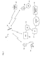
- FIG. 1 is a diagram of a satellite communication system capable of dynamically validating timing and power of satellite terminals, in accordance with an embodiment of the present invention
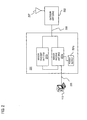
- FIG. 2 is an exemplary satellite terminal utilized in the system of FIG. 1;
- FIG. 3 is a flow chart of a process for dynamically providing timing and power validation, according to an embodiment of the present invention
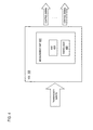
- FIG. 4 is diagram of a hub station for supporting dynamic power and timing validation in the system of FIG. 1;
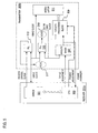
- FIG. 5 is a diagram of an inroute timing and power loop executed by the satellite terminal of FIG. 2;
- FIG. 6 is a diagram of a computer system that is capable of supporting dynamic power and timing validation, according to an embodiment of the present invention.
- FIG. 1 is a diagram of a satellite communication system capable of dynamically validating timing and power of satellite terminals, in accordance with an embodiment of the present invention.
- a satellite communication system 100 utilizes a satellite 101 to transmit information to satellite terminals (STs) 103, 105, 107, and a Network Operations Center (NOC) 109 bi-directionally (i.e., two-way).
- STs satellite terminals
- NOC Network Operations Center
- the terms “return channel”, “inroute”, and “uplink channel” are synonymously used to denote a communication channel established via the satellite 101 to transport from the STs 103, 105, 107 to the NOC 109, and the terms “receive channel”, “outroute” and “downlink channel” refer to a communication channel carrying traffic from the NOC 109 to the STs 103, 105, 107.
- the STs 103, 105, 107 originate traffic from a particular coverage area and may exchange data among themselves as well as other STs (not shown).
- the NOC 109 supports the capability to dynamically adjust timing for satellite drift and power level of the STs 103, 105, 107 to ensure proper operation in an environment that is continually changing (e.g., weather conditions and satellite position). This capability is particularly important to STs that are mobile, such as ST 107.
- the STs 103, 105, 107 are Very Small Aperture Terminals (VSAT), and provide access to a public data network, such as the Internet 111 to hosts (e.g., host 113).
- VSAT Very Small Aperture Terminals
- the uplink channel can include multiple carriers, each operating at speeds, for example, of 64kbps, 128kbps, or 256kbps. Each of these carriers is a TDMA (Time Division Multiple Access) stream, which employs several transmission schemes. Upon first use of user equipment, tools may be employed to provide initial access and to request further bandwidth as required.
- the specific bandwidth allocation scheme may be designed to ensure maximum bandwidth efficiency (i.e., minimal waste due to unused allocated bandwidth), and minimum delay of return channel data. Further, the scheme is be tunable, according to the mixture, frequency, and size of user traffic.
- the system 100 supports a two-way satellite access mechanism to the Internet 111 through the use of TDMA structured inroutes to provide a return channel between the host 113 via the ST 103 and the NOC 109.
- the system 100 transmits a burst time plan to the terminals 103, 105, 107 every frame.
- the burst time plan can be limited in size for a specific inroute group on the system 100.
- the NOC 109 manages and controls communication services and operations. For example, the NOC 109 provisions and identifies the communication channels that are to be allocated. Additionally, the NOC 109 is responsible for controlling the bandwidth that is made available to the STs 103, 105, 107. The NOC 109 also provides interfaces, such as a gateway 115, to either private Intranets (not shown) or the public Internet 111 via an ISP 117.
- the NOC 109 can support multiple receive channels (referred to as outroutes) and multiple return channels; however, the NOC 109 can be configured to provide no return channels, depending on the application.
- the NOC 109 has connectivity to the Internet 111, and supports a multitude of applications (e.g., software distribution, news retrieval, document exchange, real-time audio and video applications, etc.), which may be supplied directly from a content provider or via the Internet 111.
- the host 113 of the ST 103 can download content from an application server 119 off the Internet 111.
- the ST 105 can interface a local area network (LAN) 121, which can provide connectivity to a multiple hosts (not shown) for accessing the application server 119.
- LAN local area network
- the two-way satellite system 100 can be implemented, according to an exemplary embodiment, based upon a one-way broadcast system.
- the conventional one-way broadcast system utilizes a terrestrial link for a return channel.
- the two-way satellite system 100 obviates this requirement.
- the user terminal 101 may optionally retain the dial-up connection as a back-up connection to the Internet 111.
- the return channels may support frequency hopping to provide increased efficiency of system 100.
- a subset of return channels may be configured to support a contention protocol, such as ALOHA. It should be noted that any equivalent contention protocol may be utilized in system 100.
- An ST may randomly select a return channel with ALOHA slots.
- the NOC 109 may assign the receiver a stream on the same or a different return channel. The NOC 109 may change the frequency for the assigned stream when the site requires additional bandwidth, when another site requires additional bandwidth on the same return channel, or when the site may be used for a poll response on another return channel to keep the NOC 109 locked for the return channel.
- a return channel (or inroute) is considered locked if at least one burst has been received in the recent past.
- the two-way satellite system 100 can offer the following services to the host 113: digital package multicast delivery, and multimedia services.
- digital package delivery service the system 100 offers a multicast file transfer mechanism that allows any collection of PC files to be reliably transferred to a collection of transceivers.
- the IP multicast service carries applications, such as video, audio, financial and news feed data, etc., for broadcast to the transceivers (e.g., 109).
- the system 100 provides high-speed, cost-effective Internet access.
- the architecture of the two-way system 100 is an open architecture, which advantageously affords information (i.e., content) providers control over their content.
- the two-way system 100 provides interfaces to information providers at the NOC 109 and standard Application Programming Interfaces (APIs) on the host 113.
- the user terminal 101 is loaded with host software and drivers to interface with the transceiver 201 and to control antenna 207.
- the two-way system 100 supports the exchange of digital packages to one or more receiving hosts.
- package refers to any data (including electronic documents, multimedia data, software packages, video, audio, etc.) which can take the form of a group of PC files.
- Package delivery is used by an information provider to send packages to receiving hosts; for example, the delivery of digitized advertisements to radio and TV stations.
- a publisher may merge the package's files into a single file using an appropriate file utility (e.g., PKZIP), and subsequently load the package into the NOC 109 using an off-the-shelf file transfer mechanism (e.g., Transmission Control Protocol/ Internet Protocol (TCP/IP) file transfer protocol (FTP)).
- the publisher may control the following parameters associated with the package: addresses of the destination hosts, and delivery assurance.
- the low bit error rate and high availability of the two-way system 100 ensures that packages are delivered in one transmission (that is, without the need to retransmit).
- the publisher possesses a number of functionalities.
- the host 113 may issue retransmission requests, as needed, if segments of the package is loss or received with errors.
- the host 113 may request retransmission of only the loss or corrupt portions of the digital package via the satellite return channel, or optionally, a dial-out modem.
- the multicasting capability of the system 100 advantageously permits the one time retransmission of missing/corrupt data even though the missing/corrupt data may affect multiple hosts.
- the system 100 also supports delivery confirmation.
- a host 113 after successfully receiving a package, may send a confirmation to a package delivery server (not shown) within the NOC 109. These confirmations are tabulated and provided in the form of reports to the publisher.
- the system 100 may provide a best effort service. Under this scenario, if frames are lost on the first transmission, the receiving hosts fill in the gaps on subsequent transmissions. This mechanism helps ensure high probability of delivery without requiring use of a return link for retransmission requests.
- the digital packages contain the following fields: a transmission rate field that is configurable per package at speeds up to 4 Mbps; a forward error correction (FEC) rate for providing correction of sporadic packet loss; a priority field for specifying low, medium, or high priority; and optional topic, descriptive name, and description fields that are used by the user interface of the receiver host to present the package to the user.
- FEC forward error correction
- the package delivery service of the two-system 100 supports the simultaneous transmission of several packages and the preemption of lower priority packages to ensure the timely delivery of higher priority packages.
- the system 100 also supplies multimedia services, which provide one-way IP multicast transport.
- the NOC 109 relays a configurable set of IP multicast addresses over the downlink channel.
- An information provider may pass IP multicast packets to the NOC 109, either via a terrestrial line or via the return channel.
- the receiving hosts 113 may receive the IP multicast through the standard Winsock with IP Multicast extensions API. To prevent unauthorized access, each IP multicast address may be cryptographically protected. Thus, host 113 may only have access to an address if it has been authorized by the NOC 109.
- Hardware filtering in the receiver of the ST 103 allows the reception of any number of different IP Multicast addresses.
- the NOC 109 which provides network management functions, allocates to each multimedia information provider a committed information rate (CIR), and one or more IP multicast addresses.
- CIR committed information rate
- IP Multicast address operates as a separate data stream that is multiplexed on the one broadcast channel.
- the two-way satellite communication system 100 supports access by the host 113 in form of a personal computer (PC).
- PC personal computer
- Any type of hosts with appropriate functionalities can be utilized; e.g., personal digital assistants (PDAs), set-top boxes, cellular phones, laptop computing devices, etc.
- PDAs personal digital assistants
- set-top boxes e.g., set-top boxes, cellular phones, laptop computing devices, etc.
- FIG. 2 is an exemplary satellite terminal utilized in the system of FIG. 1.
- the ST 103 has a transceiver 201 that includes an indoor receiver unit (IRU) 201a, an indoor transmitter unit (ITU) 201b for transmitting and receiving data from the network hub 109 - denoted as a network operations center (NOC).
- the IRU 201a includes logic (not shown) that measures the strength of the receive signals in terms of a signal quality factor, which is used to automatically adjust transmission power level as well as timing.
- the terminal 103 can transmit data to the NOC 109 with a high-speed return channel, and receive data on the downlink channel of even greater speed.
- the transceiver 201 encompasses a number of hardware and software components.
- a PC host software which is resident in host 113 and supports the satellite return channel.
- the transceiver 201 includes IRU 201a, ITU 201b, a power supply 201c, and connects to an Outdoor Unit (ODU) 203.
- the ODU 203 contains a low noise block (LNB) (not shown), an antenna 207, and a radio (not shown).
- LNB low noise block
- the IRU 201a operates in the receive-only mode and controls the ITU 201b.
- the IRU 201a in an exemplary embodiment, has a Universal Serial Bus (USB) interface, which is a standard interface to host 113 to provide IRU control and data.
- the IRU 201a may be attached to the host 113 dynamically, and may be loaded with operational software and initialized by PC driver software. Received traffic is forwarded to the host 113 through a USB connection 205.
- the PC driver communicates with the IRU 201a for control over the USB channel.
- the receive chain F-connector on an RG-6 cable is connected to the IRU 201a to communicate to the LNB 305.
- the IRU 201a contains an interface that may be used to transfer data to control the transmit unit and to actually provide the transmit data to the ITU 201b. A clock is received on this channel to ensure that transmit frame timing and transmit symbol clocks are synchronized.
- Data is passed from the host 113 to the USB adapter of the host 113, which formats the data for transmission and provides both the control and data for the ITU 201a.
- the ITU 201a sends the data to the outdoor unit 203 at the appropriate time for the data to be transmitted in TDMA bursts to equipment at the NOC 109.
- each two-way transceiver is expected to have a bit-error rate less than 10 -10 more than 99.5% of the time whereby a single bit error causes the loss of an entire frame.
- the IRU 201a can be used as a stand-alone device with the host 113 via the USB interface.
- One application such application in which only the IRU 201a is required is Digital Video Broadcast (DVB).
- DVD Digital Video Broadcast
- the IRU 201a can be field upgradable with the addition of the ITU 201b.
- the ITU 201b may be a standalone component that externally may appear very similar to the IRU 201a.
- the housings of the IRU 201a and ITU 201b are in a stackable form factor.
- the ITU 201b has an Inter-Facility Link (IFL) interface (not shown) that attaches to the ODU 203 via an RG-6 interface (not shown).
- Control information and data from the ITU 201b are multiplexed onto the IFL cables 209 to the ODU 203.
- One IFL cable 209 may handle the receive patch and the other may handle the transmit path.
- the ITU 201b also includes an ITU control interface for data transfer. In addition, a pulse is received over the ITU control interface to ensure that transmit frame timing and transmit symbol clocks are properly synchronized.
- the ITU 201b may contain an RF transmitter, low phase noise oscillator, and serial data transceiver (as more fully described with respect to FIG. 5). ITU 201b modulates and transmits, in bursts utilizing in-bound carriers at, for example, rates of 64kbps or 128kbps.
- the ITU 201b may be designed to operate with and to be controlled by the IRU 201a. Although IRU 201a and ITU 201b are shown as distinct components, IRU 201a and ITU 201b may be integrated, according to an embodiment of the present invention. By way of example, a single DB-25 connector on the rear panel provides power, ground and a serial data link via which control of the transmitter is exercised. The ITU 201b may be considered a peripheral to the IRU 201a. Configuration parameters and inbound data from the IRU 201a may be input to the serial port (not shown); in addition, transmitter status information to the IRU 201a may output from the serial port.
- the IRU 201a and ITU 201b utilize dual IFL cables 209 to connect to the LNB of the ODU 203 for receiving signals from the satellite 101.
- Each cable 209 may carry the necessary power, data, and control signals from the IRU 201a and ITU 201b to the LNB, which is mounted on the antenna 207.
- the transceiver 201 supports a variety of features that enhance the flexibility and efficiency of the two-way system 100.
- Transceiver 109 can be implemented as a receive-only unit that can be later upgraded to support a two-way configuration.
- the transceiver 201 may be configured either as a receive-only package or a transmit upgrade package.
- the transceiver 201 may be designed to be an add-on capability to a standard receive-only transceiver.
- a user can either purchase an upgrade to a transceiver 201 to support a satellite-based return channel or can operate a receiver with no transmit portion for communication over the satellite 101.
- Such a receive-only system may employ a terrestrial return channel (e.g., phone line) for two-way IP traffic.
- a terrestrial return channel e.g., phone line
- the transceiver 201 supports multiple rate, high speed, receive channel.
- the transceiver 201 can support for high speed TCP/IP applications using, for example, Turbo InternetTM TCP spoofing.
- a standard USB interface to host 113 is used to connect the host 113 with the IRU 201a.
- any type of interface can be utilized (e.g., serial, parallel, Personal Computer Memory/ Card International Association (PCMCIA), Small Computer System Interface (SCSI), etc.).
- PCMCIA Personal Computer Memory/ Card International Association
- SCSI Small Computer System Interface
- the transceiver 201 supports TCP/IP applications (e.g., web browsing, electronic mail and FTP) and multimedia broadcast and multicast applications using IP Multicast (e.g.
- the transceiver 201 can also support IP multicast applications (e.g., MPEG video and package delivery). Further, the transceiver 201 can provide compression of receive and return channel traffic to enhance bandwidth efficiency.
- IP multicast applications e.g., MPEG video and package delivery
- the transceiver 201 integrates the capabilities of the broadband receiver via satellite with the capability for a satellite return channel through the use of IRU 201a and ITU 201b.
- the IRU 201a is powered by power supply 201c.
- the received channel to the transceiver 201 may be a DVB transport stream that contains multiprotocol-encapsulated IP traffic.
- a group of multiple transmit channels may be shared among several DVB transport streams.
- the transceiver 201 unlike conventional satellite systems, is controlled at the system level by the NOC 109.
- the NOC 109 has the capability to enable and disable the operation of the ITU 201b, thereby making it difficult for an authorized user to access the satellite system 100.
- the transceiver 201 nor the connected PC-based host 113 has the capability to override commands from NOC 109, even in the case in which the equipment is powered down and restarted.
- the ITU 201b can only be enabled by the NOC 109. That is, the user cannot "re-enable" a disabled ITU 201b, even through a power reset.
- the NOC 109 may instruct the ITU 201b to transmit a test pattern at a predetermined frequency. This process may not be overridden by the user, who has no capability to cause the generation of the test pattern. The user has no control over the frequency that the test pattern is sent. Thus, the above system-level control of the ITU 201 b by the NOC 109 prevents users from utilizing the resources of the satellite system 100.
- the two-way system 100 provides high-speed Internet access, in which the host 113 can connect to the Internet 111.
- the access is asymmetric, whereby the downlink channel from the NOC 109 to the user terminal 101 can be an order of magnitude greater that the uplink (or return channel).
- the host 113 in an exemplary embodiment, runs the following operating systems: Microsoft® Windows XP.
- the PC software may provide instruction and support for installation and antenna pointing (including automatic registration and configuration), package delivery, and drivers that are used by the native TCP/IP (Transmission Control Protocol/ Internet Protocol) stack to support standard applications -- including Winsock API with multicast extensions and web browsers.
- TCP/IP Transmission Control Protocol/ Internet Protocol
- the host 113 also utilizes an NDIS (Network Device Interface Specification) device driver to operate with the native TCP/IP stack for Microsoft® Windows.
- NDIS Network Device Interface Specification
- the NDIS software sends the return channel data to the IRU 201a, which in turn supplies the data to the ITU 201b.
- the packets may be alternatively sent to a dial-up interface.
- the two-way system 100 allows operation of the standard Internet applications; for example, Netscape® browser, Microsoft® Internet Explorer browser, email, NNTP Usenet News, FTP, GOPHER, etc.
- the system 100 uses a Ku- (or Ka-) band transponder to provide up to a 45 Mbps DVB-compliant broadcast channel from the NOC 109.
- data encryption standard (DES) encryption-based conditional access can be utilized to ensure that the host 113 may only access data that the host 113 is authorized to receive.
- the satellite terminals 103, 105, 107 can automatically, on a continual basis, adjust for timing and power, as next described.
- FIG. 3 is a flow chart of a process for dynamically providing timing and power validation, according to an embodiment of the present invention.
- the system 100 provides a closed-loop control process to continually measure timing and power to adjust operation of the terminals.
- This closed-loop control process is executed under normal operation; that is, no special mode of operation (e.g., test mode) is needed to conduct timing and power control.
- the system 100 in an exemplary embodiment, exhibits a star topology with respect to the manner in which the signals are measured. That is, the measurement of the signals is through a central component (i.e., the NOC 109); under such an arrangement, the terminal does not receive its transmitted carrier.
- the process of FIG. 3 is an automated procedure that may occur whenever data is received by the NOC 109 from the terminal. For the purposes of explanation, the process is described such that the NOC 109 performs signal measurements to provide feedback to the terminal to adjust transmission power; however, it is recognized that the measurements may be performed by a designated terminal.
- the host 113 requires transmitting data over a return channel supported by the satellite 101 to the NOC 109.
- the terminal 103 sends a transmission burst to the NOC 109 - alternatively, the transmission burst can be sent to a designated terminal outside of the NOC 109.
- the terminal has a transceiver 201, notably the IRU 201a, with the functionality to measure the current receive signal strength in terms of a signal quality factor (SQF) - e.g., a signal-to-noise ratio (E b /N o ).
- SQF signal quality factor
- E b /N o signal-to-noise ratio
- the ITU 201b of the transceiver 201 may adjust the power of the transmission in response to the IRU 201a.
- the IRU 201a in an exemplary embodiment, provides the SQF when the terminal transmits packets to the NOC 109.
- This information may be provided as part of "adaptation/header” information, which may coexist with the data that a site (or terminal) would normally be transmitting.
- the closed-loop control process allows for a real-time adjustment of timing and power both at the NOC 109, and at the terminal without suspending or interrupting data transmission by the host 113 (FIG. 2).
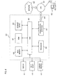
- FIG. 4 shows a diagram of a hub station (e.g., NOC 109) for supporting dynamic power and timing validation in the system, in accordance with an embodiment of the present invention.
- NOC 109 determines the timing and the power level of the burst, as in step 303.
- the burst contains a unique word (UW) to aid in detection of the start and end of the transmission burst.
- UW unique word
- the timing is measured as an offset value. Specifically, the difference between the center of the aperture associated with an expected (or estimated) the end of a unique word and the actual end of the unique word within the aperture is determined, resulting in a timing offset value.
- the power level may be measured and expressed in terms of a signal-to-noise ratio value.
- the NOC 109 in accordance with an embodiment of the present invention, contains a measurement unit 401 equipment (e.g., a hub manufactured by Aurora) that provides measurement information on every received burst from the terminal 101.
- the measurement unit 401 includes automatic gain control (AGC) circuitry 403 and timing logic 405.
- AGC automatic gain control
- the measurement unit 401 measures the receive signal strength (E b /N o ) of each burst from each terminal within the system 100 using the AGC circuitry 403.
- the AGC circuitry 403 triggers on a unique word contained within the transmission burst, as to measure the signal level until the end of the burst.
- the timing logic 405 tracks the time when each burst is received.
- the measurement unit 401 identifies the site (i.e., terminal) that sent the burst, and thus, provides a number of signal quality measurements.
- the measurement unit 401 measures the received SQF at various sites to determine whether inferior system performance is attributable to NOC degradation or site degradation.
- the measurement unit 401 also measures the received E b /N o for a terminal, thereby enabling the NOC 109 to provide feedback to the terminal if the power needs adjustment.
- the determined timing offset value is employed to account, in part, for drift of the satellite 101.
- the NOC 109 then creates a message that specifies the determined power level and timing offset value, thereby providing a control signal for the terminal to adjust, as necessary, the timing and the power level to adapt to varying channel conditions.
- the message is transmitted by the NOC 109 to the terminal.
- the terminal as well as the NOC 109 possesses the capability to adjust transmit power to counteract, for example, unfavorable temporary weather conditions and other conditions that may cause a site or system outage in a conventional system.
- the timing of the terminal similarly be adjusted for satellite drift.
- the terminal checks whether the timing and the power level that are specified in the received message require corresponding timing and power adjustment in the terminal. For example, if the power margin is proper, then the process ends; however, if the power margin is not proper (i.e., inadequate power margin or too much power margin), then the terminal adjusts the power level accordingly.
- the measurement unit 401 may periodically provide the transmit power adjustment value to each terminal to allow the terminal to locally determine if and when to adjust the transmit power; this capability exists because the measurement unit 401 receives the power level with each burst. If the measurement unit 401 measures low power for some terminals on an inroute (lower than other terminals), then the measurement unit 401 may provide information to allow the terminals with the weaker power to transmit more power.
- the present invention advantageously enhances system availability, even in poor weather conditions.
- FIG. 5 is a diagram of an inroute timing and power loop executed by the satellite terminal of FIG. 2.
- the transceiver 201 provides a high-speed, over the air return channel to the conventional low speed terrestrial backhaul.
- the ITU 201b i.e., transmitter
- the IRU 201a i.e., receiver
- the transmitter 201b is implemented entirely as firmware controlled hardware.
- the architecture of the transceiver 201 in which no CPU with embedded software running on the transmitter 201b, advantageously provides significant cost savings.
- the IRU 201a includes a demodulator (DEMOD) 501 for demodulating the control signal from the NOC 109, and a processor 503 for extracting timing and power information from the demodulated control signal.
- the processor (CPU) 503, in response, generates timing adjustment and power adjustment signals to the ITU 201b.
- the transmitter 201b in an exemplary embodiment, is considered a peripheral to the CPU. Configuration parameters and inbound data from the CPU 503 are input to a serial interface (not shown).
- the timing adjustment signal and the power adjustment signal are forwarded to an inroute timer 507 and an inroute processing block 509, respectively.
- the inroute timer 507 provides the control necessary for varying the length of the inroute frame, using a counter clock.
- the counter is pre-loaded with a value using an inroute frame register (not shown).
- the processor 503 periodically updates the inroute frame register to ensure frame synchronization.
- the counter terminal count is output as an "Inroute Frame Interrupt," which is passed to the IRU 201a via, for example, a serial interface.
- the inroute processing block 509 provides control of a modulator 511 to adjust for power and timing based on the frame synchronization information from the inroute timer 507 and the power adjustment signal from the processor 503.
- the modulator 511 is an Offset Quadrature Phase Shift Keying (O-QPSK) modulator utilizing several cascaded filters (not shown).
- the ITU 201b supports a variety of transmission functions, such as modulating and transmitting, in burst mode, the in-bound carrier to the NOC 109.
- the ITU 201b includes a Frequency Lock Loop (FLL) 513, and a Phase Lock Loop (PLL) 515, which are supported by two different oscillators 517, 519 with different clock rates (e.g., 10MHz and 32.768MHz).
- the FLL 513 corrects for frequency drift in the transmitter 10 MHz RF (Radio Frequency) time base.
- the VCXO 517 is a 10.000 MHz low noise a Temperature Compensated Voltage Controlled Crystal Oscillator (TC-VCXO) with a Transistor-Transistor Logic (TTL) compatible output.
- TC-VCXO Temperature Compensated Voltage Controlled Crystal Oscillator
- TTL Transistor-Transistor Logic
- the 10 MHz VC-TCXO frequency accuracy is accomplished by frequency locking with the outbound carrier recovered symbol clock.
- the recovered symbol clock is passed from the receiver 201 a to the transmitter 201b via the serial interface.
- the inroute processing block 509 provides a number functions with respect to sending data over the return channel.
- the block 509 reads data from an inroute data buffer (not shown), and performs the channel coding functions on the inroute data.
- the inroute processing block 509 also multiplexes Unique Word (UW) data with predetermined headers and trailers into a serial bit stream.
- UW Unique Word
- the inroute processing block 509 further generates the control/timing signals to the modulator 511 in addition to the inroute data.
- FIG. 6 is a diagram of a computer system that is capable of supporting dynamic verification and validation of timing and power of the satellite terminals, according to an embodiment of the present invention.
- the computer system 600 includes a bus 601 or other communication mechanism for communicating information and a processor 603 coupled to the bus 601 for processing information.
- the computer system 600 also includes main memory 605, such as a random access memory (RAM) or other dynamic storage device, coupled to the bus 601 for storing information and instructions to be executed by the processor 603.
- Main memory 605 can also be used for storing temporary variables or other intermediate information during execution of instructions by the processor 603.
- the computer system 600 may further include a read only memory (ROM) 607 or other static storage device coupled to the bus 601 for storing static information and instructions for the processor 603.
- a storage device 609 such as a magnetic disk or optical disk, is coupled to the bus 601 for persistently storing information and instructions.
- the computer system 600 may be coupled via the bus 601 to a display 611, such as a cathode ray tube (CRT), liquid crystal display, active matrix display, or plasma display, for displaying information to a computer user.
- a display 611 such as a cathode ray tube (CRT), liquid crystal display, active matrix display, or plasma display
- An input device 613 such as a keyboard including alphanumeric and other keys, is coupled to the bus 601 for communicating information and command selections to the processor 603.
- a cursor control 615 such as a mouse, a trackball, or cursor direction keys, for communicating direction information and command selections to the processor 603 and for controlling cursor movement on the display 611.
- the process of FIG. 3 is implemented by the computer system 600 in response to the processor 603 executing an arrangement of instructions contained in main memory 605.
- Such instructions can be read into main memory 605 from another computer-readable medium, such as the storage device 609.
- Execution of the arrangement of instructions contained in main memory 605 causes the processor 603 to perform the process steps described herein.
- processors in a multi-processing arrangement may also be employed to execute the instructions contained in main memory 605.
- hard-wired circuitry may be used in place of or in combination with software instructions to implement the embodiment of the present invention.
- embodiments of the present invention are not limited to any specific combination of hardware circuitry and software.
- the computer system 600 also includes a communication interface 617 coupled to bus 601.
- the communication interface 617 provides a two-way data communication coupling to a network link 619 connected to a local network 621.
- the communication interface 617 may be a digital subscriber line (DSL) card or modem, an integrated services digital network (ISDN) card, a cable modem, a telephone modem, or any other communication interface to provide a data communication connection to a corresponding type of communication line.
- communication interface 617 may be a local area network (LAN) card (e.g. for EthernetTM or an Asynchronous Transfer Model (ATM) network) to provide a data communication connection to a compatible LAN.
- LAN local area network
- Wireless links can also be implemented.
- communication interface 617 sends and receives electrical, electromagnetic, or optical signals that carry digital data streams representing various types of information.
- the communication interface 617 can include peripheral interface devices, such as a Universal Serial Bus (USB) interface, a PCMCIA (Personal Computer Memory Card International Association) interface, etc.
- USB Universal Serial Bus
- PCMCIA Personal Computer Memory Card International Association
- the network link 619 typically provides data communication through one or more networks to other data devices.
- the network link 619 may provide a connection through local network 621 to a host computer 623, which has connectivity to a network 625 (e.g. a wide area network (WAN) or the global packet data communication network now commonly referred to as the "Internet") or to data equipment operated by a service provider.
- the local network 621 and the network 625 both use electrical, electromagnetic, or optical signals to convey information and instructions.
- the signals through the various networks and the signals on the network link 619 and through the communication interface 617, which communicate digital data with the computer system 600, are exemplary forms of carrier waves bearing the information and instructions.
- the computer system 600 can send messages and receive data, including program code, through the network(s), the network link 619, and the communication interface 617.
- a server (not shown) might transmit requested code belonging to an application program for implementing an embodiment of the present invention through the network 625, the local network 621 and the communication interface 617.
- the processor 603 may execute the transmitted code while being received and/or store the code in the storage device 609, or other non-volatile storage for later execution. In this manner, the computer system 600 may obtain application code in the form of a carrier wave.
- Non-volatile media include, for example, optical or magnetic disks, such as the storage device 609.
- Volatile media include dynamic memory, such as main memory 605.
- Transmission media include coaxial cables, copper wire and fiber optics, including the wires that comprise the bus 601. Transmission media can also take the form of acoustic, optical, or electromagnetic waves, such as those generated during radio frequency (RF) and infrared (IR) data communications.
- RF radio frequency
- IR infrared
- Computer-readable media include, for example, a floppy disk, a flexible disk, hard disk, magnetic tape, any other magnetic medium, a CD-ROM, CDRW, DVD, any other optical medium, punch cards, paper tape, optical mark sheets, any other physical medium with patterns of holes or other optically recognizable indicia, a RAM, a PROM, and EPROM, a FLASH-EPROM, any other memory chip or cartridge, a carrier wave, or any other medium from which a computer can read.
- a floppy disk a flexible disk, hard disk, magnetic tape, any other magnetic medium, a CD-ROM, CDRW, DVD, any other optical medium, punch cards, paper tape, optical mark sheets, any other physical medium with patterns of holes or other optically recognizable indicia, a RAM, a PROM, and EPROM, a FLASH-EPROM, any other memory chip or cartridge, a carrier wave, or any other medium from which a computer can read.
- the instructions for carrying out at least part of the present invention may initially be borne on a magnetic disk of a remote computer.
- the remote computer loads the instructions into main memory and sends the instructions over a telephone line using a modem.
- a modem of a local computer system receives the data on the telephone line and uses an infrared transmitter to convert the data to an infrared signal and transmit the infrared signal to a portable computing device, such as a personal digital assistant (PDA) or a laptop.
- PDA personal digital assistant
- An infrared detector on the portable computing device receives the information and instructions borne by the infrared signal and places the data on a bus.
- the bus conveys the data to main memory, from which a processor retrieves and executes the instructions.
- the instructions received by main memory can optionally be stored on storage device either before or after execution by processor.
- an approach for automatically adjusting timing and power levels of satellite terminals 103, 105, 107 in a two-way satellite communication system 100.
- the satellite terminals 103, 105, 107 transmit bursts to a hub station 109 over a return channel.
- the hub station 109 e.g., NOC
- the hub station 109 automatically generate control messages to the satellite terminal 103, 105, 107 for selective adjustment of the timing to account for satellite drift and power level for compensating for varying weather conditions.
- the above arrangement advantageously enhances efficient use of system resources and increases system availability.
Landscapes
- Engineering & Computer Science (AREA)
- Computer Networks & Wireless Communication (AREA)
- Signal Processing (AREA)
- Physics & Mathematics (AREA)
- Astronomy & Astrophysics (AREA)
- Aviation & Aerospace Engineering (AREA)
- General Physics & Mathematics (AREA)
- Radio Relay Systems (AREA)
- Mobile Radio Communication Systems (AREA)
Applications Claiming Priority (2)
| Application Number | Priority Date | Filing Date | Title |
|---|---|---|---|
| US639558 | 1991-01-10 | ||
| US10/639,558 US20040033780A1 (en) | 2001-11-30 | 2003-08-12 | Method and system for providing dynamic timing and power validation in a two-way satellite network |
Publications (2)
| Publication Number | Publication Date |
|---|---|
| EP1507342A2 true EP1507342A2 (de) | 2005-02-16 |
| EP1507342A3 EP1507342A3 (de) | 2007-04-11 |
Family
ID=33565238
Family Applications (1)
| Application Number | Title | Priority Date | Filing Date |
|---|---|---|---|
| EP04251252A Withdrawn EP1507342A3 (de) | 2003-08-12 | 2004-03-04 | Verfahren und Anordnung zur Herstellung dynamischer Zeitreferenzen und Validierung der Leistung in einem zwei-weg Satellitennetz |
Country Status (2)
| Country | Link |
|---|---|
| US (1) | US20040033780A1 (de) |
| EP (1) | EP1507342A3 (de) |
Cited By (1)
| Publication number | Priority date | Publication date | Assignee | Title |
|---|---|---|---|---|
| CN102437907A (zh) * | 2010-09-24 | 2012-05-02 | 塔莱斯公司 | 通过辅扩频信令信号的传输配置主信号的自适应处理的方法 |
Families Citing this family (14)
| Publication number | Priority date | Publication date | Assignee | Title |
|---|---|---|---|---|
| BRPI0508484A (pt) * | 2004-03-05 | 2007-07-31 | Nextnet Wireless Inc | método e aparelho para transmissão de datagramas isócronos através de link de dados baseado em disputa |
| JP4622727B2 (ja) * | 2005-07-29 | 2011-02-02 | 日本電気株式会社 | 適応送信タイミング制御方法、無線通信システムおよび無線通信装置 |
| US8515342B2 (en) * | 2005-10-12 | 2013-08-20 | The Directv Group, Inc. | Dynamic current sharing in KA/KU LNB design |
| US8271044B2 (en) | 2007-11-21 | 2012-09-18 | Air Advantage | System and method for installation of a wireless connection |
| US8918097B2 (en) * | 2007-11-28 | 2014-12-23 | Motorola Mobility Llc | Managing service in an access network for wireless communication |
| US8135431B2 (en) | 2007-12-18 | 2012-03-13 | Gilat Satellite Networks, Ltd. | Multi-dimensional adaptive transmission technique |
| ES2769423T3 (es) * | 2012-08-24 | 2020-06-25 | Mx1 Gmbh | Un aparato y procedimiento para proporcionar un flujo conjunto de datos de IP |
| US9674804B2 (en) * | 2014-12-29 | 2017-06-06 | Hughes Network Systems, Llc | Apparatus and method for synchronizing communication between systems with different clock rates |
| US9813147B2 (en) * | 2015-01-05 | 2017-11-07 | Hughes Network Systems, Llc | Systems and methods for automatically re-ranging a satellite terminal |
| US9686027B2 (en) * | 2015-05-20 | 2017-06-20 | Viasat, Inc. | Validation of a two-way satellite communication system without utilizing a satellite |
| KR102477464B1 (ko) * | 2015-11-12 | 2022-12-14 | 삼성전자주식회사 | 무선 통신 시스템에서 음성 패킷의 크기를 제어하기 위한 장치 및 방법 |
| GB2557628B (en) | 2016-12-13 | 2020-01-01 | Inmarsat Global Ltd | Forward link power control |
| US10116038B1 (en) * | 2017-04-13 | 2018-10-30 | Verizon Patent And Licensing Inc. | Mobile hotspot system |
| CN117294340B (zh) * | 2023-09-20 | 2024-04-02 | 北京泰利斯达科技有限公司 | 一种卫星通信数据传输方法、装置、服务器及存储介质 |
Family Cites Families (9)
| Publication number | Priority date | Publication date | Assignee | Title |
|---|---|---|---|---|
| US3654395A (en) * | 1969-10-15 | 1972-04-04 | Communications Satellite Corp | Synchronization of tdma space division satellite system |
| JP2758340B2 (ja) * | 1993-02-15 | 1998-05-28 | 三菱電機株式会社 | Tdma移動通信装置のrfパワーレベルモニタ装置 |
| US5561838A (en) * | 1994-07-01 | 1996-10-01 | Motorola, Inc. | Method and apparatus for satellite handoff parameters prediction in an orbiting communications system |
| US5790939A (en) * | 1995-06-29 | 1998-08-04 | Hughes Electronics Corporation | Method and system of frame timing synchronization in TDMA based mobile satellite communication system |
| US6108317A (en) * | 1995-11-01 | 2000-08-22 | Stm Wireless, Inc. | Cyclic code phase multiple access for inbound satellite communications |
| US6529485B1 (en) * | 1997-10-20 | 2003-03-04 | Viasat, Inc. | Method for generation of accurate doppler-free local clock in satellite/wireless networks |
| WO2000031901A1 (en) * | 1998-11-24 | 2000-06-02 | Hughes Electronics Corporation | Transmit timing control messages rate reduction in a communication system by using the rate of change of a timing information |
| EP1041738A1 (de) * | 1999-03-30 | 2000-10-04 | ICO Services Ltd. | Korrektur des Dopplereffektes für eine Hochgeschwindigkeitsmobilstation in einem Mobilfunksatellitenkommunikationssystem |
| WO2002078216A1 (en) * | 2001-03-21 | 2002-10-03 | Hughes Electronics Corporation | System and method for providing closed-loop power control |
-
2003
- 2003-08-12 US US10/639,558 patent/US20040033780A1/en not_active Abandoned
-
2004
- 2004-03-04 EP EP04251252A patent/EP1507342A3/de not_active Withdrawn
Cited By (2)
| Publication number | Priority date | Publication date | Assignee | Title |
|---|---|---|---|---|
| CN102437907A (zh) * | 2010-09-24 | 2012-05-02 | 塔莱斯公司 | 通过辅扩频信令信号的传输配置主信号的自适应处理的方法 |
| CN102437907B (zh) * | 2010-09-24 | 2017-01-18 | 塔莱斯公司 | 通过辅扩频信令信号的传输配置主信号的自适应处理的方法 |
Also Published As
| Publication number | Publication date |
|---|---|
| US20040033780A1 (en) | 2004-02-19 |
| EP1507342A3 (de) | 2007-04-11 |
Similar Documents
| Publication | Publication Date | Title |
|---|---|---|
| US7656813B2 (en) | Inroute training in a two-way satellite system | |
| US6987741B2 (en) | System and method for managing bandwidth in a two-way satellite system | |
| US7164661B2 (en) | System and method for providing a two-way satellite system | |
| US6501423B2 (en) | Method and system of directing an antenna in a two-way satellite system | |
| US6650869B2 (en) | System and method for managing return channel bandwidth in a two-way satellite system | |
| US6965581B2 (en) | Transceiver in a two-way satellite system | |
| US20030058810A1 (en) | Hybrid satellite system for providing one-way and two-way communication services | |
| EP1507342A2 (de) | Verfahren und Anordnung zur Herstellung dynamischer Zeitreferenzen und Validierung der Leistung in einem zwei-weg Satellitennetz | |
| US20030050015A1 (en) | Automated signal measurement in a satellite communication system | |
| US20010043573A1 (en) | System and method for providing control of a two-way satellite system | |
| US7047456B2 (en) | Error correction for regional and dynamic factors in communications | |
| US20020000931A1 (en) | User interface for a two-way satellite communication system | |
| US7463582B2 (en) | System and method for scaling a two-way satellite system | |
| US20020009058A1 (en) | System and method for performing auto-commissioning in a two-way satellite system | |
| US20010048669A1 (en) | System interfaces in a two-way satellite system | |
| US6684059B1 (en) | Frequency generation in a wireless communication system | |
| WO2002078216A1 (en) | System and method for providing closed-loop power control |
Legal Events
| Date | Code | Title | Description |
|---|---|---|---|
| PUAI | Public reference made under article 153(3) epc to a published international application that has entered the european phase |
Free format text: ORIGINAL CODE: 0009012 |
|
| AK | Designated contracting states |
Kind code of ref document: A2 Designated state(s): AT BE BG CH CY CZ DE DK EE ES FI FR GB GR HU IE IT LI LU MC NL PL PT RO SE SI SK TR |
|
| AX | Request for extension of the european patent |
Extension state: AL HR LT LV MK |
|
| RAP1 | Party data changed (applicant data changed or rights of an application transferred) |
Owner name: HUGHES NETWORK SYSTEMS, LLC |
|
| RIC1 | Information provided on ipc code assigned before grant |
Ipc: H04B 7/212 20060101ALI20061129BHEP Ipc: H04B 7/185 20060101AFI20040421BHEP |
|
| PUAL | Search report despatched |
Free format text: ORIGINAL CODE: 0009013 |
|
| AK | Designated contracting states |
Kind code of ref document: A3 Designated state(s): AT BE BG CH CY CZ DE DK EE ES FI FR GB GR HU IE IT LI LU MC NL PL PT RO SE SI SK TR |
|
| AX | Request for extension of the european patent |
Extension state: AL LT LV MK |
|
| 17P | Request for examination filed |
Effective date: 20071004 |
|
| AKX | Designation fees paid |
Designated state(s): AT BE BG CH CY CZ DE DK EE ES FI FR GB GR HU IE IT LI LU MC NL PL PT RO SE SI SK TR |
|
| 17Q | First examination report despatched |
Effective date: 20090615 |
|
| STAA | Information on the status of an ep patent application or granted ep patent |
Free format text: STATUS: THE APPLICATION IS DEEMED TO BE WITHDRAWN |
|
| 18D | Application deemed to be withdrawn |
Effective date: 20091001 |