EP1507228B1 - Optical code reader - Google Patents
Optical code reader Download PDFInfo
- Publication number
- EP1507228B1 EP1507228B1 EP04013600A EP04013600A EP1507228B1 EP 1507228 B1 EP1507228 B1 EP 1507228B1 EP 04013600 A EP04013600 A EP 04013600A EP 04013600 A EP04013600 A EP 04013600A EP 1507228 B1 EP1507228 B1 EP 1507228B1
- Authority
- EP
- European Patent Office
- Prior art keywords
- illumination
- line
- optics
- scanner according
- focal length
- Prior art date
- Legal status (The legal status is an assumption and is not a legal conclusion. Google has not performed a legal analysis and makes no representation as to the accuracy of the status listed.)
- Active
Links
Images

Classifications
-
- G—PHYSICS
- G06—COMPUTING; CALCULATING OR COUNTING
- G06K—GRAPHICAL DATA READING; PRESENTATION OF DATA; RECORD CARRIERS; HANDLING RECORD CARRIERS
- G06K7/00—Methods or arrangements for sensing record carriers, e.g. for reading patterns
- G06K7/10—Methods or arrangements for sensing record carriers, e.g. for reading patterns by electromagnetic radiation, e.g. optical sensing; by corpuscular radiation
- G06K7/10544—Methods or arrangements for sensing record carriers, e.g. for reading patterns by electromagnetic radiation, e.g. optical sensing; by corpuscular radiation by scanning of the records by radiation in the optical part of the electromagnetic spectrum
- G06K7/10712—Fixed beam scanning
- G06K7/10722—Photodetector array or CCD scanning
- G06K7/10732—Light sources
-
- G—PHYSICS
- G06—COMPUTING; CALCULATING OR COUNTING
- G06K—GRAPHICAL DATA READING; PRESENTATION OF DATA; RECORD CARRIERS; HANDLING RECORD CARRIERS
- G06K7/00—Methods or arrangements for sensing record carriers, e.g. for reading patterns
- G06K7/10—Methods or arrangements for sensing record carriers, e.g. for reading patterns by electromagnetic radiation, e.g. optical sensing; by corpuscular radiation
- G06K7/10544—Methods or arrangements for sensing record carriers, e.g. for reading patterns by electromagnetic radiation, e.g. optical sensing; by corpuscular radiation by scanning of the records by radiation in the optical part of the electromagnetic spectrum
- G06K7/10821—Methods or arrangements for sensing record carriers, e.g. for reading patterns by electromagnetic radiation, e.g. optical sensing; by corpuscular radiation by scanning of the records by radiation in the optical part of the electromagnetic spectrum further details of bar or optical code scanning devices
- G06K7/10831—Arrangement of optical elements, e.g. lenses, mirrors, prisms
Definitions
- the invention relates to a scanner, in particular for detecting one and / or two-dimensional codes with a receiving optics, which designs the image of a reading line on a linear arrangement of a plurality of photoreceptors and a lighting arrangement, with which the entire reading line is illuminated in a line.
- Such prior art scanners also called line scanners, can identify one-dimensional codes located in the reading line without the need for relative movement between the scanner and the code.
- Scanners according to the operating principle described above, often have the disadvantage that due to insufficient light conditions, or illuminance in the read line, the codes can only be incorrect, incomplete or in the extreme case, not identified at all. Even if a low illuminance could be compensated with a longer exposure time, this will reduce the reading speed. Particularly in conveyor technology, a large field of application for these scanners, these are the conveying speed reducing influences, of great disadvantage.
- the codes are illuminated in the prior art with high-energy light sources, for example sodium vapor lamps, laser diodes, or many diffused emitting LEDs, which in turn has a large-volume, expensive scanner results in addition, a high electrical power consumption has caused a strong self-heating.
- an optical scanner which forms the light of several light sources with a cylindrical lens to a reading line to illuminate the reading line.
- a relatively large proportion of the light emitted by the light sources is not concentrated on the read line, ultimately resulting in less efficient illumination of the read line.
- US Pat. No. 5,504,317 it is known from US Pat. No. 5,504,317 to concentrate the light of a plurality of light sources on a read line by means of a cylindrical lens.
- the illumination arrangement is arranged relatively close to the read line. However, so that this illumination optics does not hinder the receive beam path, the illumination optics and the receiving optics are aligned at an angle to each other.
- light is not limited to the visible light. Under “light” are generally electromagnetic radiation, ie UV light, IR light and visible light to understand, which can usually be used for the operation of these scanners.
- the invention has for its object to increase by optical means, the efficiency of the lighting arrangement such that with a few light sources, which are operated with low energy input, a sufficiently high illuminance is generated, which allows the safe detection of the codes in the shortest possible time.
- the invention provides a scanner with a receiving optics, which designs the image of a reading line on a linear arrangement of a plurality of photoreceptors, and a lighting arrangement, with the entire reading line in a line with a plurality of substantially punctiform light sources arranged side by side in a line , Illuminated, according to the invention, the illumination arrangement has an anamorphic illumination optics, for generating a line-shaped illumination line.
- the advantage of this inventive lighting arrangement is the fact that, through the use of the special anamorphic illumination optics, the radiation emitted by the light sources is largely completely concentrated only on the illumination line.
- the resulting high illuminance in the illumination line not only allows a short exposure and thus code reading time, but also increases the distance of the useful light to the disturbing ambient light.
- the anamorphic illumination optical system is composed of an at least two-stage imaging system.
- this is a short focal length toric convex lens in the immediate vicinity of each individual light source for beam shaping in the meridional plane and at a greater distance, a long focal length, refractive cylindrical lens which detects the light emission of all light sources and influences the beam shaping in the sagittal plane.
- the short focal length toric convex lens has an aspherical contour in its meridional section, because this can improve the aperture ratio and / or reduce the spherical aberration.
- the function of the second long-focal-length refractive cylinder lens which determines the beam guidance in the sagittal plane for all light sources in common, is produced by a hollow cylindrical mirror with a round or parabolic cross-section.
- a parabolic cross-section it is possible, in particular when using a parabolic cross-section, to expand the optically effective opening of the hollow cylinder mirror in relation to its focal length to a value of about 1: 0.5, which corresponds to a numerical aperture of greater than 1. It is thus possible by means of a simple optical component to concentrate a majority of the radiation emitted by all the light sources used on the illumination line.
- optical components of the anamorphic illumination optics are at least partially diffractive optical elements or produced as Fresnel lenses in injection or embossing technology.
- Another advantage of the invention is the fact that, depending on the task on the number and spatial density of the light sources, together with the short focal toric convex lenses, the total length of the illumination can be adjusted within wide limits to the task.
- the overlapping of the partial illumination lines produced by the individual light sources can be determined by the spatial density of the light sources together with an optimized dimensioning of the toric convex lenses, so that they have a substantially homogeneous illumination intensity in the resulting illumination line of all light sources in the longitudinal direction ,
- a further advantage of this two-stage anamorphic illumination optical system is that the width of the illumination line can be determined via the imaging scale of the cylinder optics which are effective in the sagittal plane. This makes it possible to optimally adapt the illumination line to the width of the reading line of the scanner.
- an embodiment that is particularly preferred from the point of view of economical manufacturability is given when the individual short-focal-length toric convex lenses assigned to the light sources are designed in one piece as a lens array for beam shaping in the meridional plane.
- a plurality of LEDs which are arranged on a line at a defined distance, for example on a printed circuit board, can be joined together in one operation with the toric convex lenses of short focal length.
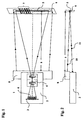
- the scanner 1 in a housing part 2 has a linear arrangement of a plurality of photoreceptors 3.
- This arrangement of the photoreceptor 3 is designed as a spatially resolving detector, in particular as a CCD Unie or CMOS line.
- a reception optics 4, also shown schematically in the housing part 2, designs an image of a reading line 5 located at a reading distance s from the scanner on the surface 6 of the arrangement of the photoreceivers 3.
- a code 7 consisting of differently contrasting contrast marks is applied to the cause individual photocurrents different photocurrents, so that in a downstream evaluation unit, the existing information in the code can be detected.
- a plurality of substantially punctiform light sources are located in a further housing part 8, whose emitted light radiation illuminates a lighting line 9 by means of an anamorphic illumination optics according to the invention.
- the read line 5 and the illumination line 9 overlap at the reading distance s. This is achieved by the optical axis 10 of the illumination optical unit forming an angle with the optical axis 11 of the receiving optical system in the meridional plane. If the scanner is operated in this V-shaped arrangement only in a fixed predetermined reading distance s, then the housing parts 2 and 8 may be firmly connected to each other, or consist of a common housing.
- the housing 2 with the receiving optics and the photoreceptors as well as the housing 8 with the light sources and the anamorphic illumination optics according to the invention adjustable in different angular positions mechanically connected to each other.
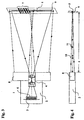
- FIG. 3 shows a preferred embodiment of the scanner in which the anamorphic illumination optics incorporated in the housing part 8 are arranged coplanar with the photoreceivers 3 and the receiving optics 4.
- FIG. 5 a section through the anamorphic illumination optics in the meridional plane, a plurality of substantially punctiform light sources 12, 12 ', to 12 n , in particular LEDs, can be seen, which are arranged offset in line with one another by the distance a.
- the emitted radiation is focused in each case by a short-focal-length toric convex lens 13, 13 ', 13 n in the meridional plane such that the further beam path in this plane has only a slightly divergent character.
- the individual sub-beam 15, 15 n are directed to the illumination line 9.
- the toric of the convex lenses 13, 13 ',, n to 13 n certain divergence of each partial beam of rays 15 to 15 of the line of illumination overlap each other in the plane 9, the partial illumination lines in such a way that, despite the substantially gausförmigen energy distribution of the partial illumination lines a common illumination line 9 with approximately homogeneous energy profile is present.
- FIG. 6 shows, in the sagittal profile cross section of the anamorphic illumination optics, a punctiform light source 12 and the cross section of the toric convex lens 13 in a sectional direction perpendicular to FIG. 3. It can be seen that this is a first approximation to a curved disk of constant center thickness, the optical power is therefore very low. For this reason, the radiation of the light sources will impinge on the surface of the hollow cylinder mirror 14 without any significant change in direction.
- the hollow cylindrical mirror 14 is dimensioned such that the radiation reflected thereon is focused on the illumination line 9 in this sagittal plane.
- the width of the illumination line 9 generated in the focus can thus be influenced via the focal length of the cylinder optics as well as the object and image-side cutting widths.
- the optical function of the hollow cylindrical mirror 14 can also be produced with a continuous plane, concave or biconvex cylindrical lens.
- the beam path from the light source 12, 12 ', to 12 n to the illumination line 9 undergoes no beam reversal, but optionally increases the overall length of the illumination optics.
Abstract
Description
Die Erfindung betrifft einen Scanner, insbesondere zur Erfassung von ein- und/oder von zweidimensionalen Codes mit einer Empfangsoptik, die das Bild einer Leselinie auf einer linienförmigen Anordnung von mehreren Photoempfängem entwirft und einer Beleuchtungsanordnung, mit der die gesamte Leselinie linienförmig ausgeleuchtet wird.The invention relates to a scanner, in particular for detecting one and / or two-dimensional codes with a receiving optics, which designs the image of a reading line on a linear arrangement of a plurality of photoreceptors and a lighting arrangement, with which the entire reading line is illuminated in a line.
Derartige aus dem Stand der Technik bekannte Scanner, auch Linienscanner genannt, können eindimensionale Code die sich in der Leselinie befinden identifizieren, ohne dass eine Relativbewegung zwischen Scanner und Code erfolgen muss.Such prior art scanners, also called line scanners, can identify one-dimensional codes located in the reading line without the need for relative movement between the scanner and the code.
Wird der Code jedoch mittels einer Förderbewegung am Scanner vorbeigeführt, ist dieser aufgrund der Relativbewegung in der Lage, auch zweidimensionale Codes zu erfassen.However, if the code is guided past the scanner by means of a conveying movement, it is able to detect two-dimensional codes due to the relative movement.
Scanner, nach dem vorstehend beschriebenen Funktionsprinzip, weisen oftmals den Nachteil auf, dass infolge unzureichender Lichtverhältnisse, bzw. Beleuchtungsstärke in der Leselinie, die Codes nur fehlerhaft, unvollständig oder im Grenzfall überhaupt nicht identifiziert werden können.
Auch wenn eine geringe Beleuchtungsstärke mit einer längeren Belichtungszeit ausgeglichen werden könnte, hat dies zur Folge, dass dadurch die Lesegeschwindigkeit reduziert wird. Besonders in der Fördertechnik, einem großen Einsatzgebiet für diese Scanner, sind diese, die Fördergeschwindigkeit reduzierenden Einflüsse, von großem Nachteil. Um diese Einschränkung zu umgehen, werden die Codes nach dem Stand der Technik mit energiereichen Lichtquellen, zum Beispiel Natriumdampflampen, Laserdioden, bzw. vielen diffus abstrahlenden LED's beleuchtet, was wiederum einen großvolumigen, teueren Scanner zur Folge hat, der darüber hinaus einen hohen elektrischen Leistungsverbrauch hat und eine starke Eigenerwärmung verursacht.Scanners, according to the operating principle described above, often have the disadvantage that due to insufficient light conditions, or illuminance in the read line, the codes can only be incorrect, incomplete or in the extreme case, not identified at all.
Even if a low illuminance could be compensated with a longer exposure time, this will reduce the reading speed. Particularly in conveyor technology, a large field of application for these scanners, these are the conveying speed reducing influences, of great disadvantage. To circumvent this limitation, the codes are illuminated in the prior art with high-energy light sources, for example sodium vapor lamps, laser diodes, or many diffused emitting LEDs, which in turn has a large-volume, expensive scanner results in addition, a high electrical power consumption has caused a strong self-heating.
Auch ist beispielsweise aus der WO 01/72028 ein optischer Scanner bekannt, der zur Ausleuchtung der Leselinie das Licht mehrerer Lichtquellen mit einer Zylinderlinse zu einer Leselinie formt. Durch den Einsatz von nur einer relativ langbrennweitigen Zylinderlinse als strahlformendes optisches Element wird jedoch ein verhältnismäßig großer Anteil des von den Lichtquellen ausgesandten Lichtes nicht auf der Leselinie konzentriert, was letztlich zu einer nicht sehr effizienten Ausleuchtung der Leselinie führt.
Des Weiteren ist aus der US 5,504,317 bekannt, mittels einer Zylinderlinse das Licht mehrerer Lichtquellen auf eine Leselinie zu konzentrieren. Hierbei wird die Beleuchtungsanordnung relativ nahe der Leselinie angeordnet ist. Damit jedoch diese Beleuchtungsoptik den Empfangsstrahlengang nicht behindert, sind die Beleuchtungsoptik und die Empfangsoptik unter einem Winkel zueinander ausgerichtet. Um die dadurch zwangsläufig auftretende Parallaxe zwischen Beleuchtungs- und Empfangsstrahlengang insbesondere bei verändertem Leseabstand auszugleichen, ist es notwendig, die Lesebene nicht linienförmig sondern in Form einer langgezogenen Fläche auszuleuchten. Dadurch wird das von den Lichtquellen ausgesandte Licht nicht nur auf der Leselinie, sondern auf einer Lesefläche konzentriert wodurch sich die Effizienz der Beleuchtungsanordnung sehr verringert.Also, for example, from WO 01/72028 an optical scanner is known, which forms the light of several light sources with a cylindrical lens to a reading line to illuminate the reading line. However, by using only a relatively long focal length cylindrical lens as the beam shaping optical element, a relatively large proportion of the light emitted by the light sources is not concentrated on the read line, ultimately resulting in less efficient illumination of the read line.
Furthermore, it is known from US Pat. No. 5,504,317 to concentrate the light of a plurality of light sources on a read line by means of a cylindrical lens. In this case, the illumination arrangement is arranged relatively close to the read line. However, so that this illumination optics does not hinder the receive beam path, the illumination optics and the receiving optics are aligned at an angle to each other. In order to compensate for the inevitably occurring parallax between the illumination and reception beam path, in particular with a changed reading distance, it is necessary to illuminate the reading plane not linear but in the form of an elongated surface. As a result, the light emitted by the light sources is concentrated not only on the reading line, but on a reading surface, thereby greatly reducing the efficiency of the lighting arrangement.
Der Begriff "Licht" ist dabei nicht auf das sichtbare Licht beschränkt. Unter "Licht" sind allgemein elektromagnetische Strahlen, also UV-Licht, IR-Licht sowie sichtbares Licht zu verstehen, welches üblicherweise für den Betrieb dieser Scanner eingesetzt werden kann.The term "light" is not limited to the visible light. Under "light" are generally electromagnetic radiation, ie UV light, IR light and visible light to understand, which can usually be used for the operation of these scanners.
Der Erfindung liegt die Aufgabe zugrunde, mit optischen Mitteln die Effizienz der Beleuchtungsanordnung derart zu steigern, dass mit wenigen Lichtquellen, die mit geringem Energieeinsatz betrieben werden, eine ausreichend hohe Beleuchtungsstärke erzeugt wird, die das sichere Erkennen der Codes in möglichst kurzer Zeit ermöglicht.The invention has for its object to increase by optical means, the efficiency of the lighting arrangement such that with a few light sources, which are operated with low energy input, a sufficiently high illuminance is generated, which allows the safe detection of the codes in the shortest possible time.
Zur Lösung dieser Aufgabe sieht die Erfindung einen Scanner mit einer Empfangsoptik vor, die das Bild einer Leselinie auf einer linienförmigen Anordnung von mehreren Photoempfängem entwirft, und einer Beleuchtungsanordnung, mit der die gesamte Leselinie linienförmig mit mehreren nebeneinander in einer Linie angeordneten, im Wesentlichen punktförmigen Lichtquellen, ausgeleuchtet wird, wobei erfindungsgemäß die Beleuchtungsanordnung eine anamorphotischen Beleuchtungsoptik, zur Erzeugung einer linienförmige Beleuchtungslinie, aufweist.To achieve this object, the invention provides a scanner with a receiving optics, which designs the image of a reading line on a linear arrangement of a plurality of photoreceptors, and a lighting arrangement, with the entire reading line in a line with a plurality of substantially punctiform light sources arranged side by side in a line , Illuminated, according to the invention, the illumination arrangement has an anamorphic illumination optics, for generating a line-shaped illumination line.
Der Vorteil dieser erfinderischen Beleuchtungsanordnung ist darin zu sehen, dass durch den Einsatz der speziellen anamorphotischen Beleuchtungsoptik, die von den Lichtquellen abgegebenen Strahlung weitgehend vollständig nur auf die Beleuchtungslinie konzentriert wird. Die dadurch erzielbare hohe Beleuchtungsstärke in der Beleuchtungslinie erlaubt nicht nur eine kurze Belichtungs- und somit Codelesezeit, sondern erhöht gleichzeitig den Abstand des Nutzlichtes zum störenden Umgebungslicht.The advantage of this inventive lighting arrangement is the fact that, through the use of the special anamorphic illumination optics, the radiation emitted by the light sources is largely completely concentrated only on the illumination line. The resulting high illuminance in the illumination line not only allows a short exposure and thus code reading time, but also increases the distance of the useful light to the disturbing ambient light.
Bevorzugt ist es, wenn die anamorphotische Beleuchtungsoptik aus einem mindestens zweistufigen Abbildungssystem zusammengesetzt ist. Erfindungsgemäß handelt es sich dabei um eine kurzbrennweitige torische Konvexlinse in der unmittelbaren Nähe jeder einzeinen Lichtquelle zur Strahlformung in der Meridionalebene und in einem größeren Abstand, eine die Lichtabstrahlung aller Lichtquellen erfassende langbrennweitige, refraktive Zylinderlinse, welche die Strahlformung in der Sagittalebene beeinflusst. Von Vorteil ist es, wenn die kurzbrennweitige torische Konvexlinse in ihrem Meridionalschnitt eine asphärische Kontur aufweist, weil damit das Öffnungsverhältnis verbessert und/oder die sphärische Aberration verringert werden kann.It is preferred if the anamorphic illumination optical system is composed of an at least two-stage imaging system. According to the invention, this is a short focal length toric convex lens in the immediate vicinity of each individual light source for beam shaping in the meridional plane and at a greater distance, a long focal length, refractive cylindrical lens which detects the light emission of all light sources and influences the beam shaping in the sagittal plane. It is advantageous if the short focal length toric convex lens has an aspherical contour in its meridional section, because this can improve the aperture ratio and / or reduce the spherical aberration.
Von Vorteil ist es femer, wenn die Funktion der zweiten langbrennweitigen refraktiven Zylinderlinse, welche gemeinsamen für alle Lichtquellen die Strahlführung in der Sagittalebene bestimmt, von einem Hohlzylinderspiegel mit rundem oder parabolischem Querschnitt erzeugt wird. Durch diese Maßnahme ist es möglich, insbesondere bei Verwendung eines parabolischen Querschnittes, die optisch wirksame Öffnung des Hohlzylinderspiegels im Verhältnis zur seiner Brennweite auf einen Wert von über 1:0,5 zu erweitem, was einer numerischen Apertur von größer 1 entspricht.
Es ist somit mittels einer einfachen Optikkomponente möglich, einen Großteil der von allen eingesetzten Lichtquellen abgegebenen Strahlung auf die Beleuchtungslinie zu konzentrieren.It is furthermore advantageous if the function of the second long-focal-length refractive cylinder lens, which determines the beam guidance in the sagittal plane for all light sources in common, is produced by a hollow cylindrical mirror with a round or parabolic cross-section. By this measure, it is possible, in particular when using a parabolic cross-section, to expand the optically effective opening of the hollow cylinder mirror in relation to its focal length to a value of about 1: 0.5, which corresponds to a numerical aperture of greater than 1.
It is thus possible by means of a simple optical component to concentrate a majority of the radiation emitted by all the light sources used on the illumination line.
Besonders vorteilhaft ist es, wenn die optischen Komponenten der anamorphotischen Beleuchtungsoptik zumindest teilweise diffraktive optische Elemente sind oder als Fresnel-Linsen in Spritz- bzw. Prägetechnik hergestellt werden.It is particularly advantageous if the optical components of the anamorphic illumination optics are at least partially diffractive optical elements or produced as Fresnel lenses in injection or embossing technology.
Ein weiterer Vorteil der Erfindung ist darin zu sehen, dass in Abhängigkeit von der Aufgabenstellung über die Anzahl und die räumliche Dichte der Lichtquellen, zusammen mit den kurzbrennweitigen torischen Konvexlinsen, die Gesamtlänge der Beleuchtungslinie in weiten Grenzen an die Aufgabenstellung angepasst werden kann.Another advantage of the invention is the fact that, depending on the task on the number and spatial density of the light sources, together with the short focal toric convex lenses, the total length of the illumination can be adjusted within wide limits to the task.
Vorteilhaft ist femer, dass durch die räumliche Dichte der Lichtquellen zusammen mit einer optimierten Dimensionierung der kurzbrennweitigen torischen Konvexlinsen die Überlappung der durch die einzelnen Lichtquellen erzeugten Teilbeleuchtlinien so bestimmt werden kann, dass diese in der resultierenden Beleuchtungslinie von allen Lichtquellen eine weitgehend homogene Beleuchtungsstärke in Längsrichtung aufweist.It is also advantageous that the overlapping of the partial illumination lines produced by the individual light sources can be determined by the spatial density of the light sources together with an optimized dimensioning of the toric convex lenses, so that they have a substantially homogeneous illumination intensity in the resulting illumination line of all light sources in the longitudinal direction ,
Ein weiterer Vorteil dieser zweistufigen anamorphotischen Beleuchtungsoptik liegt darin, dass über den Abbildungsmaßstab der in der Sagittalebene wirksamen Zylinderoptik die Breite der Beleuchtungslinie bestimmbar ist. Dadurch ist es möglich, die Beleuchtungslinie optimal auf die Breite der Leselinie des Scanners anzupassen.A further advantage of this two-stage anamorphic illumination optical system is that the width of the illumination line can be determined via the imaging scale of the cylinder optics which are effective in the sagittal plane. This makes it possible to optimally adapt the illumination line to the width of the reading line of the scanner.
Eine besonders unter dem Gesichtspunkt der wirtschaftlichen Herstellbarkeit bevorzugte Ausführungsform ist dann gegeben, wenn die einzelnen den Lichtquellen zugeordneten kurzbrennweitigen torischen Konvexlinsen zur Strahlformung in der Meridionalebene einstückig als Linsenarray ausgebildet sind. In diesem Fall können zum Beispiel mehrere LED's, die auf einer Linie in definiertem Abstand beispielsweise auf einer Leiterplatte angeordnet sind, in einem Arbeitsgang mit den kurzbrennweitigen torischen Konvexlinsen zusammengefügt werden.An embodiment that is particularly preferred from the point of view of economical manufacturability is given when the individual short-focal-length toric convex lenses assigned to the light sources are designed in one piece as a lens array for beam shaping in the meridional plane. In this case, for example, a plurality of LEDs, which are arranged on a line at a defined distance, for example on a printed circuit board, can be joined together in one operation with the toric convex lenses of short focal length.
Die Erfindung wird im Folgenden beispielhaft unter Bezugnahme auf die Figuren erläutert; in diesen zeigen:
- Fig. 1
- eine schematische Draufsicht auf einen Scanner mit der erfindungsgemäßen Beleuchtungsanordnung in V-Anordnung,
- Fig. 2
- eine Seitenansicht des Scanners gemäß Fig. 1,
- Fig. 3
- eine schematische Draufsicht auf einen Scanner mit der erfindungsgemäßen Beleuchtungsanordnung in koplanarer Anordnung,
- Fig. 4
- eine Seitenansicht des Scanners gemäß Fig. 3,
- Fig. 5
- einen Schnitt durch die anamorphotische Beleuchtungsoptik in der Meridionalebene, und
- Fig. 6
- einen Schnitt in der Sagittalebene durch die anamorphotischen Beleuchtungsoptik.
- Fig. 1
- a schematic plan view of a scanner with the illumination arrangement according to the invention in V-arrangement,
- Fig. 2
- a side view of the scanner of FIG. 1,
- Fig. 3
- a schematic plan view of a scanner with the illumination arrangement according to the invention in a coplanar arrangement,
- Fig. 4
- a side view of the scanner of FIG. 3,
- Fig. 5
- a section through the anamorphic illumination optics in the meridional plane, and
- Fig. 6
- a section in the sagittal plane through the anamorphic illumination optics.
Gemäß Fig. 1 besitzt der Scanner 1 in einem Gehäuseteil 2 eine linienförmige Anordnung von mehreren Photoempfängem 3. Diese Anordnung der Photoempfänger 3 ist als ein ortsauflösender Detektor ausgebildet, insbesondere als eine CCD-Unie oder CMOS-Linie. Eine ebenfalls im Gehäuseteil 2 eingebaute, schematisch dargestellte Empfangsoptik 4 entwirft ein Bild von einer in einem Leseabstand s vom Scanner entfernten Leselinie 5 auf der Oberfläche 6 der Anordnung der Photoempfänger 3. Somit wird ein Code 7, bestehend aus unterschiedlich stark remittierenden Kontrastmarken, auf den einzelnen Photoempfängern unterschiedliche Photoströme hervorrufen, so dass in einer nachgeschalteten Auswerteeinheit die im Code vorhandene Information erfasst werden kann.1, the
Damit die auf den einzelnen Photoempfängem hervorgerufenen unterschiedlichen Photoströme schnell und sicher ausgewertet werden können ist es notwendig, dass auf der Leselinie 5 eine möglichst hohe Beleuchtungsstärke vorhanden ist. Um dies zu erreichen, befinden sich in einem weiteren Gehäuseteil 8 mehrere im Wesentlichen punktförmige Lichtquellen, deren abgegebene Lichtstrahlung mittels einer erfindungsgemäßen anamorphotischen Beleuchtungsoptik eine Beleuchtungslinie 9 ausleuchten.In order that the different photocurrents produced on the individual photoreceptors can be evaluated quickly and reliably, it is necessary that the greatest possible illuminance is present on the
Wie in der Seitenansicht der Fig. 2 aufgezeigt, überlagern sich im Leseabstand s die Leselinie 5 und die Beleuchtungslinie 9. Dies wird dadurch erreicht, dass die optische Achse 10 der Beleuchtungsoptik in der Meridionalebene mit der optischen Achse 11 der Empfangsoptik einen Winkel bilden. Wird der Scanner bei dieser V-förmigen Anordnung nur in einem fest vorgegebenen Leseabstand s betrieben, so können die Gehäuseteile 2 und 8 fest miteinander verbunden sein, bzw. aus einem gemeinsamen Gehäuse bestehen.
Um jedoch unterschiedlich große Leseabstände s zwischen dem Scanner und der Leselinie 5 einstellen zu können kann es vorgesehen sein, das Gehäuse 2 mit der Empfangsoptik und den Photoempfängem sowie das Gehäuse 8 mit den Lichtquellen und der erfindungsgemäßen anamorphotischen Beleuchtungsoptik in verschiedenen Winkelpositionen justierbar miteinander mechanisch zu verbinden.As shown in the side view of FIG. 2, the read
However, in order to be able to set different sizes of reading distances s between the scanner and the
Sollte die Aufgabenstellung diese V-förmige Anordnung jedoch nicht zulassen, ist es ebenfalls möglich, zum Beispiel über einen hier nicht dargestellten teildurchlässigen Spiegel die Beleuchtung und den Empfang in einer echten Autokollimation anzuordnen.However, should the task not allow this V-shaped arrangement, it is also possible to arrange for example via a partially transparent mirror, not shown here, the lighting and the reception in a true autocollimation.
In Fig. 3 ist eine bevorzugte Ausführungsform des Scanners dargestellt, bei welcher die im Gehäuseteil 8 eingebaute anamorphotische Beleuchtungsoptik koplanar mit den Photoempfängern 3 und der Empfangsoptik 4 angeordnet ist.FIG. 3 shows a preferred embodiment of the scanner in which the anamorphic illumination optics incorporated in the
Der Vorteil dieser koplanaren Anordnung, insbesondere bei unterschiedlichem Leseabstand s, wird deutlich aus der in Fig. 4 dargestellten Seitenansicht. Da hier die optische Achse 10 der Beleuchtungsoptik in der Meridionalebene mit der optischen Achse 11 der Empfangsoptik in einer Ebene liegen, ist eine Symmetrie der leselinie 5 mit der Beleuchtungslinie 9 über einen großen Leseabstand s vorhanden.The advantage of this coplanar arrangement, in particular with different reading distance s, becomes clear from the side view illustrated in FIG. Since the
In Fig. 5, einem Schnitt durch die anamorphotische Beleuchtungsoptik in der Meridionalebene, sind mehrere im Wesentlichen punktförmige Lichtquellen 12, 12', bis 12n, insbesondere LED's, zu sehen, die zeilenförmig zueinander versetzt um den Abstand a angeordnet sind. Die abgegebene Strahlung wird von jeweils einer kurzbrennweitigen torischen Konvexlinse 13, 13', bis 13n in der Meridionalebene derart fokussiert, dass der weitere Strahlverlauf in dieser Ebene nur noch einen leicht divergenten Charakter aufweist. Dabei ist es möglich, die Vielzahl der torischen Konvexlinsen 13, 13', bis 13n mit Hilfe einer Kunststoffspritzform oder als Glaspressling einstückig herzustellen, um dadurch die Justage und Montage der Beleuchtungsoptik zu vereinfachen. Nach einer Strahlumlenkung an einem sich über alle Lichtquellen 12, 12', bis 12n erstreckenden Hohlzylinderspiegel 14 werden die einzelnen Teilstrahlbündel 15, bis 15n zur Beleuchtungslinie 9 gerichtet. Durch die von den torischen Konvexlinsen 13, 13', bis 13n bestimmte Divergenz der einzelnen Teilstrahlbündel 15, bis 15n überlappen sich in der Ebene der Beleuchtungslinie 9 die Teilbeleuchtungslinien derart, dass trotz der im Wesentlichen gausförmigen Energieverteilung der Teilbeleuchtungslinien eine gemeinsame Beleuchtungslinie 9 mit annähernd homogenem Energieverlauf vorhanden ist.In FIG. 5, a section through the anamorphic illumination optics in the meridional plane, a plurality of substantially punctiform
Fig. 6 zeigt im sagittalen Profilquerschnitt der anamorphotischen Beleuchtungsoptik eine punktförmige Lichtquelle 12 sowie den Querschnitt der torischen Konvexlinse 13 in einer gegenüber Fig. 3 rechtwinkligen Schnittrichtung. Es ist zu erkennen, dass es sich dabei in erster Näherung um eine gebogene Scheibe konstanter Mittendicke handelt, deren optische Brechkraft demzufolge sehr gering ist. Aus diesem Grunde wird die Strahlung der Lichtquellen ohne wesentliche Richtungsänderung auf die Oberfläche des Hohlzylinderspiegels 14 auftreffen. Der Hohlzylinderspiegel 14 ist so dimensioniert, dass die daran reflektierte Strahlung in dieser Sagittalebene auf der Beleuchtungslinie 9 fokussiert ist.FIG. 6 shows, in the sagittal profile cross section of the anamorphic illumination optics, a punctiform
Die im Fokus erzeugte Breite der Beleuchtungslinie 9 ist somit über die Brennweite der Zylinderoptik sowie der objekt- und bildseitigen Schnittweiten beeinflussbar.The width of the
Wenn eine hohe numerische Apertur gewählt wird, d. h. der Sinus des halben Öffnungswinkels α gegen 1 geht, ist es von Vorteil, den kreisförmigen Querschnitt des Hohlzylinderspiegels 14 mit einer parabolischen Kontur auszubilden.If a high numerical aperture is chosen, i. H. the sine of half the opening angle α goes against 1, it is advantageous to form the circular cross section of the hollow
Die optische Funktion des Hohlzylinderspiegels 14 ist auch mit einer durchgehenden plan-, konkav- oder bikonvexen Zylinderlinse herstellbar. In diesem Fall erfährt der Strahlverlauf von den Lichtquelle 12, 12', bis 12n zur Beleuchtungslinie 9 keine Strahlumkehr, jedoch vergrößert sich gegebenenfalls die Baulänge der Beleuchtungsoptik. The optical function of the hollow
Claims (10)
- Scanner (1), in particular for detecting one- and/or two-dimensional codes, comprising a reception optics which projects the image of a reading line (5) onto a linear arrangement of a number of photoreceivers (3), and an anamorphic illumination arrangement with the aid of which the entire reading line is illuminated linearly by a number of substantially punctiform light sources (12, 12', 12n) arranged next to one another in a line, characterized in that the illumination arrangement is composed of an at least two-stage imaging system which has in the vicinity of each light source a short focal length toroidal convex lens (13, 13', 13n) for the purpose of beam shaping in the meridional plane and, downstream thereof, a common long focal length refractive cylindrical optics (14) acting in the sagittal plane.
- Scanner according to Claim 1, characterized in that the long focal length cylindrical optics acting in the sagittal plane comprises a hollow cylindrical mirror having a round or parabolic cross section.
- Scanner according to one of the preceding claims, characterized in that the anamorphic illumination optics has a high numerical aperture in the meridional plane and/or in the sagittal plane.
- Scanner according to one of the preceding claims, characterized in that the short focal length, toroidal convex lenses of the anamorphic illumination optics have an aspheric contour in the meridional section.
- Scanner according to one of the preceding claims, characterized in that the optical components of the anamorphic illumination optics are at least partially diffractive optical elements.
- Scanner according to one of the preceding claims, characterized in that the diffractive optical elements are designed as Fresnel lenses.
- Scanner according to one of the preceding claims, characterized in that the overall length of the illumination line can be set via the number and the spatial density of the light sources, together with the short focal length, toroidal convex lenses.
- Scanner according to one of the preceding claims, characterized in that the spatial density of the light sources is selected together with the dimensioning of the short focal length, toroidal convex lenses such that the illumination level is approximately homogeneously distributed in the longitudinal direction of the illumination line.
- Scanner according to one of the preceding claims, characterized in that the width of the illumination line can be determined via the imaging scale of the cylindrical optics active in the sagittal plane.
- Scanner according to one of the preceding claims, characterized in that the anamorphic illumination optics is designed in one piece as a lens array in the meridional plane.
Applications Claiming Priority (2)
| Application Number | Priority Date | Filing Date | Title |
|---|---|---|---|
| DE10337329A DE10337329A1 (en) | 2003-08-12 | 2003-08-12 | code reader |
| DE10337329 | 2003-08-12 |
Publications (2)
| Publication Number | Publication Date |
|---|---|
| EP1507228A1 EP1507228A1 (en) | 2005-02-16 |
| EP1507228B1 true EP1507228B1 (en) | 2006-04-26 |
Family
ID=33560319
Family Applications (1)
| Application Number | Title | Priority Date | Filing Date |
|---|---|---|---|
| EP04013600A Active EP1507228B1 (en) | 2003-08-12 | 2004-06-09 | Optical code reader |
Country Status (5)
| Country | Link |
|---|---|
| US (1) | US7252237B2 (en) |
| EP (1) | EP1507228B1 (en) |
| AT (1) | ATE324637T1 (en) |
| DE (2) | DE10337329A1 (en) |
| ES (1) | ES2262068T3 (en) |
Cited By (1)
| Publication number | Priority date | Publication date | Assignee | Title |
|---|---|---|---|---|
| US8496173B2 (en) | 2011-07-11 | 2013-07-30 | Sick Ag | Camera-based code reader and method for its adjusted manufacturing |
Families Citing this family (5)
| Publication number | Priority date | Publication date | Assignee | Title |
|---|---|---|---|---|
| GB9722766D0 (en) | 1997-10-28 | 1997-12-24 | British Telecomm | Portable computers |
| DE102005031710B4 (en) * | 2005-07-05 | 2014-12-24 | Sick Ag | Optoelectronic sensor |
| ATE536593T1 (en) * | 2005-12-30 | 2011-12-15 | Datalogic Scanning Group Srl | ILLUMINATION LENS FOR AN OPTICAL CODE READER |
| US20090140048A1 (en) * | 2007-11-30 | 2009-06-04 | Symbol Technologies, Inc. | CPC Illumination Apparatus for an Imaging-Based Bar Code Reader |
| US8006906B2 (en) * | 2009-02-24 | 2011-08-30 | Symbol Technologies, Inc. | Arrangement for and method of generating uniform distributed line pattern for imaging reader |
Family Cites Families (13)
| Publication number | Priority date | Publication date | Assignee | Title |
|---|---|---|---|---|
| US4820911A (en) * | 1986-07-11 | 1989-04-11 | Photographic Sciences Corporation | Apparatus for scanning and reading bar codes |
| DE3717305C1 (en) | 1987-05-22 | 1988-07-28 | Mahlo Gmbh & Co Kg | Method and device for measuring the weft or stitch course position of textile webs |
| DE3742485A1 (en) * | 1987-12-15 | 1989-06-29 | Sick Optik Elektronik Erwin | OPTICAL SCANNER |
| JP3122452B2 (en) * | 1990-09-10 | 2001-01-09 | 日立工機株式会社 | Optical scanning device |
| DE4031633A1 (en) | 1990-10-05 | 1992-04-16 | Sick Optik Elektronik Erwin | OPTICAL INSPECTION DEVICE |
| JP2788152B2 (en) * | 1992-06-22 | 1998-08-20 | 松下電器産業株式会社 | Barcode reader |
| US5504317A (en) * | 1994-01-05 | 1996-04-02 | Opticon, Inc. | Optical reader |
| DE19804129C1 (en) * | 1998-02-03 | 1999-08-19 | Rjm Rheinmetall Jena Image Tec | Method and arrangement for obtaining image information about surface structures |
| US6098887A (en) * | 1998-09-11 | 2000-08-08 | Robotic Vision Systems, Inc. | Optical focusing device and method |
| US6066857A (en) * | 1998-09-11 | 2000-05-23 | Robotic Vision Systems, Inc. | Variable focus optical system |
| DE10009493A1 (en) | 2000-02-29 | 2001-08-30 | Sick Ag | scanner |
| EP1281271B1 (en) * | 2000-03-17 | 2017-03-15 | Datalogic Automation Inc. | Coplanar camera scanning system |
| US6773142B2 (en) * | 2002-01-07 | 2004-08-10 | Coherent, Inc. | Apparatus for projecting a line of light from a diode-laser array |
-
2003
- 2003-08-12 DE DE10337329A patent/DE10337329A1/en not_active Withdrawn
-
2004
- 2004-06-09 ES ES04013600T patent/ES2262068T3/en active Active
- 2004-06-09 EP EP04013600A patent/EP1507228B1/en active Active
- 2004-06-09 AT AT04013600T patent/ATE324637T1/en not_active IP Right Cessation
- 2004-06-09 DE DE502004000468T patent/DE502004000468D1/en active Active
- 2004-08-09 US US10/914,865 patent/US7252237B2/en active Active
Cited By (1)
| Publication number | Priority date | Publication date | Assignee | Title |
|---|---|---|---|---|
| US8496173B2 (en) | 2011-07-11 | 2013-07-30 | Sick Ag | Camera-based code reader and method for its adjusted manufacturing |
Also Published As
| Publication number | Publication date |
|---|---|
| ES2262068T3 (en) | 2006-11-16 |
| ATE324637T1 (en) | 2006-05-15 |
| DE502004000468D1 (en) | 2006-06-01 |
| US20050035203A1 (en) | 2005-02-17 |
| EP1507228A1 (en) | 2005-02-16 |
| DE10337329A1 (en) | 2005-03-10 |
| US7252237B2 (en) | 2007-08-07 |
Similar Documents
| Publication | Publication Date | Title |
|---|---|---|
| EP1688861B1 (en) | Code reader | |
| EP2789900B1 (en) | Light module for a motor vehicle lighting device | |
| EP1096432B1 (en) | Device for counting and/or sorting coins | |
| EP0894247B1 (en) | Device for measuring temperature without contact | |
| EP1742168B1 (en) | Optoelectronic sensor | |
| DE102008014349B4 (en) | Optical sensor | |
| DE102013108800B4 (en) | Lighting device and method for generating a lighting field | |
| EP0025188B1 (en) | Optical arrangement for a photodetector | |
| EP1507228B1 (en) | Optical code reader | |
| EP1246148A2 (en) | Device for monitoring a protection area | |
| DE102016212088A1 (en) | Device for limiting an angle of incidence for a spectrometer and method for operating such a device | |
| DE102009058807A1 (en) | Sensor for checking value documents | |
| EP1362473B1 (en) | Device and method for linear illumination of an object using leds and an elliptical mirror | |
| DE102009012273A1 (en) | Optical sensor | |
| DE3514014A1 (en) | LIGHTING DEVICE FOR AUTOMATIC READING | |
| DE102022129827B3 (en) | OPTOELECTRONIC SENSOR | |
| DE3702636A1 (en) | IMAGE READER | |
| EP3971470B1 (en) | High resolution vehicle headlamp | |
| DE202022106339U1 (en) | Photoelectronic sensor | |
| WO2004006560A1 (en) | Line illumination | |
| DE102017120877A1 (en) | Optoelectronic sensor system | |
| DE202022106338U1 (en) | Photoelectronic sensor | |
| DE10205294B4 (en) | Optoelectronic device | |
| WO2018007590A1 (en) | Optical beam shaping unit, distance measuring device and laser illuminator | |
| EP0764867B1 (en) | CCD line scanner for opto-electronically scanning of an object |
Legal Events
| Date | Code | Title | Description |
|---|---|---|---|
| PUAI | Public reference made under article 153(3) epc to a published international application that has entered the european phase |
Free format text: ORIGINAL CODE: 0009012 |
|
| AK | Designated contracting states |
Kind code of ref document: A1 Designated state(s): AT BE BG CH CY CZ DE DK EE ES FI FR GB GR HU IE IT LI LU MC NL PL PT RO SE SI SK TR |
|
| AX | Request for extension of the european patent |
Extension state: AL HR LT LV MK |
|
| 17P | Request for examination filed |
Effective date: 20050311 |
|
| 17Q | First examination report despatched |
Effective date: 20050502 |
|
| GRAP | Despatch of communication of intention to grant a patent |
Free format text: ORIGINAL CODE: EPIDOSNIGR1 |
|
| AKX | Designation fees paid |
Designated state(s): AT BE BG CH CY CZ DE DK EE ES FI FR GB GR HU IE IT LI LU MC NL PL PT RO SE SI SK TR |
|
| GRAS | Grant fee paid |
Free format text: ORIGINAL CODE: EPIDOSNIGR3 |
|
| GRAA | (expected) grant |
Free format text: ORIGINAL CODE: 0009210 |
|
| AK | Designated contracting states |
Kind code of ref document: B1 Designated state(s): AT BE BG CH CY CZ DE DK EE ES FI FR GB GR HU IE IT LI LU MC NL PL PT RO SE SI SK TR |
|
| PG25 | Lapsed in a contracting state [announced via postgrant information from national office to epo] |
Ref country code: CZ Free format text: LAPSE BECAUSE OF FAILURE TO SUBMIT A TRANSLATION OF THE DESCRIPTION OR TO PAY THE FEE WITHIN THE PRESCRIBED TIME-LIMIT Effective date: 20060426 Ref country code: SK Free format text: LAPSE BECAUSE OF FAILURE TO SUBMIT A TRANSLATION OF THE DESCRIPTION OR TO PAY THE FEE WITHIN THE PRESCRIBED TIME-LIMIT Effective date: 20060426 Ref country code: RO Free format text: LAPSE BECAUSE OF FAILURE TO SUBMIT A TRANSLATION OF THE DESCRIPTION OR TO PAY THE FEE WITHIN THE PRESCRIBED TIME-LIMIT Effective date: 20060426 Ref country code: SI Free format text: LAPSE BECAUSE OF FAILURE TO SUBMIT A TRANSLATION OF THE DESCRIPTION OR TO PAY THE FEE WITHIN THE PRESCRIBED TIME-LIMIT Effective date: 20060426 Ref country code: FI Free format text: LAPSE BECAUSE OF FAILURE TO SUBMIT A TRANSLATION OF THE DESCRIPTION OR TO PAY THE FEE WITHIN THE PRESCRIBED TIME-LIMIT Effective date: 20060426 Ref country code: IE Free format text: LAPSE BECAUSE OF FAILURE TO SUBMIT A TRANSLATION OF THE DESCRIPTION OR TO PAY THE FEE WITHIN THE PRESCRIBED TIME-LIMIT Effective date: 20060426 Ref country code: NL Free format text: LAPSE BECAUSE OF FAILURE TO SUBMIT A TRANSLATION OF THE DESCRIPTION OR TO PAY THE FEE WITHIN THE PRESCRIBED TIME-LIMIT Effective date: 20060426 Ref country code: PL Free format text: LAPSE BECAUSE OF FAILURE TO SUBMIT A TRANSLATION OF THE DESCRIPTION OR TO PAY THE FEE WITHIN THE PRESCRIBED TIME-LIMIT Effective date: 20060426 |
|
| REG | Reference to a national code |
Ref country code: GB Ref legal event code: FG4D Free format text: NOT ENGLISH |
|
| GBT | Gb: translation of ep patent filed (gb section 77(6)(a)/1977) |
Effective date: 20060426 |
|
| REG | Reference to a national code |
Ref country code: IE Ref legal event code: FG4D Free format text: LANGUAGE OF EP DOCUMENT: GERMAN |
|
| REF | Corresponds to: |
Ref document number: 502004000468 Country of ref document: DE Date of ref document: 20060601 Kind code of ref document: P |
|
| PG25 | Lapsed in a contracting state [announced via postgrant information from national office to epo] |
Ref country code: BE Free format text: LAPSE BECAUSE OF NON-PAYMENT OF DUE FEES Effective date: 20060630 Ref country code: MC Free format text: LAPSE BECAUSE OF NON-PAYMENT OF DUE FEES Effective date: 20060630 |
|
| PG25 | Lapsed in a contracting state [announced via postgrant information from national office to epo] |
Ref country code: SE Free format text: LAPSE BECAUSE OF FAILURE TO SUBMIT A TRANSLATION OF THE DESCRIPTION OR TO PAY THE FEE WITHIN THE PRESCRIBED TIME-LIMIT Effective date: 20060726 Ref country code: DK Free format text: LAPSE BECAUSE OF FAILURE TO SUBMIT A TRANSLATION OF THE DESCRIPTION OR TO PAY THE FEE WITHIN THE PRESCRIBED TIME-LIMIT Effective date: 20060726 |
|
| PG25 | Lapsed in a contracting state [announced via postgrant information from national office to epo] |
Ref country code: PT Free format text: LAPSE BECAUSE OF FAILURE TO SUBMIT A TRANSLATION OF THE DESCRIPTION OR TO PAY THE FEE WITHIN THE PRESCRIBED TIME-LIMIT Effective date: 20060926 |
|
| NLV1 | Nl: lapsed or annulled due to failure to fulfill the requirements of art. 29p and 29m of the patents act | ||
| REG | Reference to a national code |
Ref country code: IE Ref legal event code: FD4D |
|
| REG | Reference to a national code |
Ref country code: ES Ref legal event code: FG2A Ref document number: 2262068 Country of ref document: ES Kind code of ref document: T3 |
|
| ET | Fr: translation filed | ||
| RAP2 | Party data changed (patent owner data changed or rights of a patent transferred) |
Owner name: SICK AG |
|
| PLBE | No opposition filed within time limit |
Free format text: ORIGINAL CODE: 0009261 |
|
| STAA | Information on the status of an ep patent application or granted ep patent |
Free format text: STATUS: NO OPPOSITION FILED WITHIN TIME LIMIT |
|
| 26N | No opposition filed |
Effective date: 20070129 |
|
| PG25 | Lapsed in a contracting state [announced via postgrant information from national office to epo] |
Ref country code: AT Free format text: LAPSE BECAUSE OF NON-PAYMENT OF DUE FEES Effective date: 20060609 |
|
| BERE | Be: lapsed |
Owner name: SICK A.G. Effective date: 20060630 |
|
| PG25 | Lapsed in a contracting state [announced via postgrant information from national office to epo] |
Ref country code: GR Free format text: LAPSE BECAUSE OF FAILURE TO SUBMIT A TRANSLATION OF THE DESCRIPTION OR TO PAY THE FEE WITHIN THE PRESCRIBED TIME-LIMIT Effective date: 20060727 |
|
| PG25 | Lapsed in a contracting state [announced via postgrant information from national office to epo] |
Ref country code: BG Free format text: LAPSE BECAUSE OF FAILURE TO SUBMIT A TRANSLATION OF THE DESCRIPTION OR TO PAY THE FEE WITHIN THE PRESCRIBED TIME-LIMIT Effective date: 20060726 Ref country code: EE Free format text: LAPSE BECAUSE OF FAILURE TO SUBMIT A TRANSLATION OF THE DESCRIPTION OR TO PAY THE FEE WITHIN THE PRESCRIBED TIME-LIMIT Effective date: 20060426 |
|
| PG25 | Lapsed in a contracting state [announced via postgrant information from national office to epo] |
Ref country code: HU Free format text: LAPSE BECAUSE OF FAILURE TO SUBMIT A TRANSLATION OF THE DESCRIPTION OR TO PAY THE FEE WITHIN THE PRESCRIBED TIME-LIMIT Effective date: 20061027 Ref country code: TR Free format text: LAPSE BECAUSE OF FAILURE TO SUBMIT A TRANSLATION OF THE DESCRIPTION OR TO PAY THE FEE WITHIN THE PRESCRIBED TIME-LIMIT Effective date: 20060426 Ref country code: LU Free format text: LAPSE BECAUSE OF NON-PAYMENT OF DUE FEES Effective date: 20060609 |
|
| PG25 | Lapsed in a contracting state [announced via postgrant information from national office to epo] |
Ref country code: CY Free format text: LAPSE BECAUSE OF FAILURE TO SUBMIT A TRANSLATION OF THE DESCRIPTION OR TO PAY THE FEE WITHIN THE PRESCRIBED TIME-LIMIT Effective date: 20060426 |
|
| PGFP | Annual fee paid to national office [announced via postgrant information from national office to epo] |
Ref country code: ES Payment date: 20120628 Year of fee payment: 9 |
|
| PGFP | Annual fee paid to national office [announced via postgrant information from national office to epo] |
Ref country code: CH Payment date: 20130621 Year of fee payment: 10 |
|
| REG | Reference to a national code |
Ref country code: CH Ref legal event code: PL |
|
| PG25 | Lapsed in a contracting state [announced via postgrant information from national office to epo] |
Ref country code: LI Free format text: LAPSE BECAUSE OF NON-PAYMENT OF DUE FEES Effective date: 20140630 Ref country code: CH Free format text: LAPSE BECAUSE OF NON-PAYMENT OF DUE FEES Effective date: 20140630 |
|
| REG | Reference to a national code |
Ref country code: ES Ref legal event code: FD2A Effective date: 20160105 |
|
| PG25 | Lapsed in a contracting state [announced via postgrant information from national office to epo] |
Ref country code: ES Free format text: LAPSE BECAUSE OF NON-PAYMENT OF DUE FEES Effective date: 20140610 |
|
| REG | Reference to a national code |
Ref country code: FR Ref legal event code: PLFP Year of fee payment: 13 |
|
| PGFP | Annual fee paid to national office [announced via postgrant information from national office to epo] |
Ref country code: GB Payment date: 20160628 Year of fee payment: 13 |
|
| PGFP | Annual fee paid to national office [announced via postgrant information from national office to epo] |
Ref country code: FR Payment date: 20160621 Year of fee payment: 13 |
|
| GBPC | Gb: european patent ceased through non-payment of renewal fee |
Effective date: 20170609 |
|
| REG | Reference to a national code |
Ref country code: FR Ref legal event code: ST Effective date: 20180228 |
|
| PG25 | Lapsed in a contracting state [announced via postgrant information from national office to epo] |
Ref country code: GB Free format text: LAPSE BECAUSE OF NON-PAYMENT OF DUE FEES Effective date: 20170609 |
|
| PG25 | Lapsed in a contracting state [announced via postgrant information from national office to epo] |
Ref country code: FR Free format text: LAPSE BECAUSE OF NON-PAYMENT OF DUE FEES Effective date: 20170630 |
|
| PGFP | Annual fee paid to national office [announced via postgrant information from national office to epo] |
Ref country code: DE Payment date: 20230620 Year of fee payment: 20 |
|
| PGFP | Annual fee paid to national office [announced via postgrant information from national office to epo] |
Ref country code: IT Payment date: 20230630 Year of fee payment: 20 |