EP1507066B1 - Center-located cutter teeth on shrouded turbine blades - Google Patents
Center-located cutter teeth on shrouded turbine blades Download PDFInfo
- Publication number
- EP1507066B1 EP1507066B1 EP04254717.4A EP04254717A EP1507066B1 EP 1507066 B1 EP1507066 B1 EP 1507066B1 EP 04254717 A EP04254717 A EP 04254717A EP 1507066 B1 EP1507066 B1 EP 1507066B1
- Authority
- EP
- European Patent Office
- Prior art keywords
- bucket
- axis
- turbine
- tip shroud
- shroud
- Prior art date
- Legal status (The legal status is an assumption and is not a legal conclusion. Google has not performed a legal analysis and makes no representation as to the accuracy of the status listed.)
- Expired - Lifetime
Links
- 239000007789 gas Substances 0.000 description 8
- 230000037361 pathway Effects 0.000 description 3
- 230000008439 repair process Effects 0.000 description 2
- 238000007789 sealing Methods 0.000 description 2
- 238000011144 upstream manufacturing Methods 0.000 description 2
- 238000001816 cooling Methods 0.000 description 1
- 238000005336 cracking Methods 0.000 description 1
- 230000000694 effects Effects 0.000 description 1
- 230000005484 gravity Effects 0.000 description 1
- 230000013011 mating Effects 0.000 description 1
- 238000005259 measurement Methods 0.000 description 1
- 230000003068 static effect Effects 0.000 description 1
Images

Classifications
-
- F—MECHANICAL ENGINEERING; LIGHTING; HEATING; WEAPONS; BLASTING
- F01—MACHINES OR ENGINES IN GENERAL; ENGINE PLANTS IN GENERAL; STEAM ENGINES
- F01D—NON-POSITIVE DISPLACEMENT MACHINES OR ENGINES, e.g. STEAM TURBINES
- F01D5/00—Blades; Blade-carrying members; Heating, heat-insulating, cooling or antivibration means on the blades or the members
- F01D5/12—Blades
- F01D5/14—Form or construction
- F01D5/141—Shape, i.e. outer, aerodynamic form
-
- F—MECHANICAL ENGINEERING; LIGHTING; HEATING; WEAPONS; BLASTING
- F01—MACHINES OR ENGINES IN GENERAL; ENGINE PLANTS IN GENERAL; STEAM ENGINES
- F01D—NON-POSITIVE DISPLACEMENT MACHINES OR ENGINES, e.g. STEAM TURBINES
- F01D5/00—Blades; Blade-carrying members; Heating, heat-insulating, cooling or antivibration means on the blades or the members
- F01D5/12—Blades
- F01D5/22—Blade-to-blade connections, e.g. for damping vibrations
- F01D5/225—Blade-to-blade connections, e.g. for damping vibrations by shrouding
-
- F—MECHANICAL ENGINEERING; LIGHTING; HEATING; WEAPONS; BLASTING
- F05—INDEXING SCHEMES RELATING TO ENGINES OR PUMPS IN VARIOUS SUBCLASSES OF CLASSES F01-F04
- F05B—INDEXING SCHEME RELATING TO WIND, SPRING, WEIGHT, INERTIA OR LIKE MOTORS, TO MACHINES OR ENGINES FOR LIQUIDS COVERED BY SUBCLASSES F03B, F03D AND F03G
- F05B2240/00—Components
- F05B2240/20—Rotors
- F05B2240/33—Shrouds which are part of or which are rotating with the rotor
-
- F—MECHANICAL ENGINEERING; LIGHTING; HEATING; WEAPONS; BLASTING
- F05—INDEXING SCHEMES RELATING TO ENGINES OR PUMPS IN VARIOUS SUBCLASSES OF CLASSES F01-F04
- F05D—INDEXING SCHEME FOR ASPECTS RELATING TO NON-POSITIVE-DISPLACEMENT MACHINES OR ENGINES, GAS-TURBINES OR JET-PROPULSION PLANTS
- F05D2240/00—Components
- F05D2240/20—Rotors
- F05D2240/30—Characteristics of rotor blades, i.e. of any element transforming dynamic fluid energy to or from rotational energy and being attached to a rotor
Definitions
- the present invention relates to turbine buckets having airfoil tip shrouds and, particularly, to a shroud for a stage 2 bucket having a tip seal extending between opposite ends of the shroud, with a cutter tooth located along said tip seal, substantially centered between the opposite ends of the shroud in the direction of rotation of the bucket.
- a tip shroud seal typically projects radially outwardly from the outermost surface of the shroud, and extends circumferentially between opposite ends of the shroud in the direction of rotation of the turbine rotor.
- the tip shroud seal conventionally extends radially into a groove formed in a stationary shroud opposing the rotating tip shroud.
- the stationary shroud has a honeycomb pathway.
- a cutter tooth is provided at the leading edge of the tip shroud seal so as to cut a wider groove in the honeycomb pathway of the stationary shroud than the width of the tip shroud seal. This enables leakage flow between the high and low pressure regions on opposite sides of the tip shroud seal within the groove. While this results in an undesirable decrease in pressure drop across the airfoil with resulting diminishment of sealing capability, the lost efficiency is compensated by an increase in the stability of the airfoil.
- WO 02/25065 describes a seal system provided between a rotating subassembly and a static subassembly.
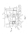
- the first stage comprises a plurality of circumferentially spaced nozzles 14 and buckets 16.
- the nozzles are circumferentially spaced one from the other and fixed about the longitudinal center axis of the rotor.
- the first stage buckets 16 are mounted on the turbine rotor 18 via a rotor wheel 20.
- the second stage of the turbine 12 includes a plurality of circumferentially spaced nozzles 22 and a plurality of circumferentially spaced buckets 24, also mounted on the rotor 18, via rotor wheel 26.
- the third stage includes a plurality of circumferentially spaced nozzles 28 and buckets 30 mounted on rotor 18 via wheel 32. It will be appreciated that the nozzles and buckets lie directly in the hot gas path 10 of the turbine, the direction of flow of the hot gas through the hot gas path 10 indicated by the arrow 34.
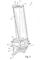
- each bucket 24 is provided with a platform 36, a shank 38 and substantially or near axial entry dovetail 40 for connection with a complementary-shaped mating dovetail, not shown, on the rotor wheel 26.
- An axial entry dovetail may be provided with the airfoil profile of this invention.
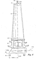
- each bucket 24 also has an airfoil or airfoil portion 42 with a tip shroud 44 at the radially outer tip of the airfoil portion.
- the tip shroud 44 is formed with an elongated radially projecting tip shroud seal 46 that extends between opposite ends of the tip shroud, in a circumferential direction, i.e., in the direction of rotation of the bucket. It will be appreciated that adjacent shrouds are not connected one to the other. Rather, adjacent shrouds bear against one another in their registering end configurations 50, best seen in Figure 6 .
- the direction of rotation of the airfoil 42 and bucket of which it forms a part is indicated by the arrow 48, also in Figure 6 .
- the tip shroud seal 46 on the rotating bucket is adapted for sealing in a stationary groove 52 formed in an adjacent stationary shroud ( Figure 1 ).
- the stationary shroud includes a honeycomb structure (not shown) within the groove 52 formed with a pathway for the tip seal 46. Consequently, the tip shroud seal 46 produces, in use, a differential pressure on opposite sides of the airfoil portion 42 of the bucket.
- the tip shroud seal 46 and the configuration generally of the tip shroud 44 are formed similarly as in the prior art.
- the cutter tooth 54 lies along the tip shroud seal, generally intermediate the opposite ends 56, 58 of the tip shroud, and preferably substantially at the center of the tip shroud in both the circumferential and axial directions. As illustrated, the cutter tooth 54 radially overlies a central portion of the airfoil portion 42.
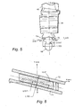
- the center point 63 of the cutter tooth 54 which is made up of two circumferentially (i.e., in the rotation direction) offset sections 62, 64, is located relative to the X and Y axes.
- the X-axis represents a flow direction of hot exhaust gases toward the turbine exhaust and is generally parallel to the rotor axis.
- the Y-axis represents a direction of rotation of the bucket 24 and hence of the rotor wheel 26.
- the location of the radial Z-axis extending perpendicular to the X-Y plane, is determined relative to predetermined reference surfaces in the shank 38 of the bucket.
- the Z-axis is located (1.866 inches) 4.74 cm from a forward edge 66 of the forward bucket tang 68, along the X-axis, and (0.517 inches) 1.31 cm from an outside edge of the seal pin 72 extending along said entry dovetail, as measured in a direction normal to the shank of the bucket.
- the distance between the outside edges of the respective pins 72, 73 is (1.153 in) 2.93 cm. for pin diameters of (.224 in) 0.57cm. It should be noted that the shank portion of the bucket is rotated 15.5° in the clockwise direction about the Z-axis.
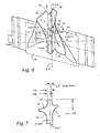
- the dimensions defining the location of the Z-axis as shown in Figure 4 are better appreciated with reference to Figure 8 which shows the true reference orientations for the measurements.
- the upstream (relative to the direction of rotation) edge 60 of the cutter tooth section 64 is located (0.550 ⁇ 0.25 inches) 1.40 ⁇ 0.64 cm, along the Y-axis, i.e., measured from the Z-X plane, in the direction of rotation of the airfoil.
- each tooth section 62, 64 at the radially outer tip thereof is about 0.25 in) 0.64 cm, plus or minus accepted machine tolerances, i.e. ⁇ (.160 in) 0.41 cm.
- the upstream edge of the tooth section 62 lies substantially (0.376 inches ⁇ .160 in) 0.96 ⁇ 0.41 cm along the Y-axis, also in the direction of rotation of the bucket.
- Figure 7 shows certain additional details of the tip shroud 44 and its relation to the Z-axis.
- the forward edge of the tip seal 46 is located (0.88 in) 2.24cm. from the Y-Z plane, while the width dimension of the seal 46 at its radial tip is (0.175 in) 0.44 cm.
- the sides of the tip seal 46 both taper inwardly in the radial outward direction by 5.3°.
Landscapes
- Engineering & Computer Science (AREA)
- Mechanical Engineering (AREA)
- General Engineering & Computer Science (AREA)
- Physics & Mathematics (AREA)
- Fluid Mechanics (AREA)
- Turbine Rotor Nozzle Sealing (AREA)
Applications Claiming Priority (2)
| Application Number | Priority Date | Filing Date | Title |
|---|---|---|---|
| US10/638,302 US6890150B2 (en) | 2003-08-12 | 2003-08-12 | Center-located cutter teeth on shrouded turbine blades |
| US638302 | 2003-08-12 |
Publications (3)
| Publication Number | Publication Date |
|---|---|
| EP1507066A2 EP1507066A2 (en) | 2005-02-16 |
| EP1507066A3 EP1507066A3 (en) | 2006-11-15 |
| EP1507066B1 true EP1507066B1 (en) | 2015-10-07 |
Family
ID=33565210
Family Applications (1)
| Application Number | Title | Priority Date | Filing Date |
|---|---|---|---|
| EP04254717.4A Expired - Lifetime EP1507066B1 (en) | 2003-08-12 | 2004-08-05 | Center-located cutter teeth on shrouded turbine blades |
Country Status (4)
| Country | Link |
|---|---|
| US (1) | US6890150B2 (enExample) |
| EP (1) | EP1507066B1 (enExample) |
| JP (1) | JP2005106053A (enExample) |
| CN (1) | CN100507217C (enExample) |
Families Citing this family (26)
| Publication number | Priority date | Publication date | Assignee | Title |
|---|---|---|---|---|
| US7066713B2 (en) * | 2004-01-31 | 2006-06-27 | United Technologies Corporation | Rotor blade for a rotary machine |
| US7134838B2 (en) * | 2004-01-31 | 2006-11-14 | United Technologies Corporation | Rotor blade for a rotary machine |
| US7396205B2 (en) | 2004-01-31 | 2008-07-08 | United Technologies Corporation | Rotor blade for a rotary machine |
| US7094023B2 (en) * | 2004-02-09 | 2006-08-22 | United Technologies Corporation | Shroud honeycomb cutter |
| US7094032B2 (en) * | 2004-02-26 | 2006-08-22 | Richard Seleski | Turbine blade shroud cutter tip |
| EP1712740A1 (de) * | 2005-04-05 | 2006-10-18 | Siemens Aktiengesellschaft | Schaufel für eine Strömungsmaschine und Strömungsmaschine mit einer Anzahl von Schaufeln |
| US20060280610A1 (en) * | 2005-06-13 | 2006-12-14 | Heyward John P | Turbine blade and method of fabricating same |
| JP2007231868A (ja) * | 2006-03-02 | 2007-09-13 | Hitachi Ltd | 蒸気タービン動翼およびそれを用いた蒸気タービン並びに蒸気タービン発電プラント |
| US7527477B2 (en) * | 2006-07-31 | 2009-05-05 | General Electric Company | Rotor blade and method of fabricating same |
| US7686568B2 (en) * | 2006-09-22 | 2010-03-30 | General Electric Company | Methods and apparatus for fabricating turbine engines |
| US9009965B2 (en) * | 2007-05-24 | 2015-04-21 | General Electric Company | Method to center locate cutter teeth on shrouded turbine blades |
| US20090097979A1 (en) * | 2007-07-31 | 2009-04-16 | Omer Duane Erdmann | Rotor blade |
| US20090041611A1 (en) | 2007-08-07 | 2009-02-12 | General Electric Company | Braze alloy composition with enhanced oxidation resistance and methods of using the same |
| CH702980A1 (de) * | 2010-03-31 | 2011-10-14 | Alstom Technology Ltd | Dichtstruktur an einem Deckband einer Turbinenlaufschaufel. |
| US20110255958A1 (en) * | 2010-04-16 | 2011-10-20 | General Electric Company | Seal member for hot gas path component |
| US8905715B2 (en) | 2011-03-17 | 2014-12-09 | General Electric Company | Damper and seal pin arrangement for a turbine blade |
| US8905711B2 (en) * | 2011-05-26 | 2014-12-09 | United Technologies Corporation | Ceramic matrix composite vane structures for a gas turbine engine turbine |
| RU2553049C2 (ru) | 2011-07-01 | 2015-06-10 | Альстом Текнолоджи Лтд | Лопатка ротора турбины, ротор турбины и турбина |
| US8631577B2 (en) | 2011-07-22 | 2014-01-21 | Pratt & Whitney Canada Corp. | Method of fabricating integrally bladed rotor and stator vane assembly |
| US9097128B2 (en) * | 2012-02-28 | 2015-08-04 | General Electric Company | Seals for rotary devices and methods of producing the same |
| WO2014189875A1 (en) * | 2013-05-21 | 2014-11-27 | Siemens Energy, Inc. | Turbine blade tip shroud |
| US9828858B2 (en) | 2013-05-21 | 2017-11-28 | Siemens Energy, Inc. | Turbine blade airfoil and tip shroud |
| KR101623816B1 (ko) | 2014-07-28 | 2016-05-25 | 두산중공업 주식회사 | 질량감소형 축방향 삽입 버킷 |
| FR3073595B1 (fr) * | 2017-11-15 | 2020-02-07 | Safran Helicopter Engines | Joint a labyrinthe comprenant une lechette dotee d'un deflecteur |
| RU195437U1 (ru) * | 2019-10-07 | 2020-01-28 | Федеральное государственное бюджетное образовательное учреждение высшего образования "Рыбинский государственный авиационный технический университет имени П.А. Соловьева" | Турбинная рабочая лопатка с несимметричной внутренней и внешней поверхностями бандажной полки |
| KR102790892B1 (ko) * | 2021-11-30 | 2025-04-02 | 두산에너빌리티 주식회사 | 터빈 블레이드, 이를 포함하는 터빈 및 가스터빈 |
Family Cites Families (28)
| Publication number | Priority date | Publication date | Assignee | Title |
|---|---|---|---|---|
| US4053111A (en) * | 1976-12-06 | 1977-10-11 | Windamatic Systems, Inc. | Apparatus and method for producing distributed stator windings |
| US4227703A (en) * | 1978-11-27 | 1980-10-14 | General Electric Company | Gas seal with tip of abrasive particles |
| US4961310A (en) * | 1989-07-03 | 1990-10-09 | General Electric Company | Single shaft combined cycle turbine |
| GB2236147B (en) * | 1989-08-24 | 1993-05-12 | Rolls Royce Plc | Gas turbine engine with turbine tip clearance control device and method of operation |
| US5197281A (en) * | 1990-04-03 | 1993-03-30 | General Electric Company | Interstage seal arrangement for airfoil stages of turbine engine counterrotating rotors |
| WO1992017686A1 (en) * | 1991-04-02 | 1992-10-15 | Rolls-Royce Plc | Turbine casing |
| EP0528138B1 (de) * | 1991-08-08 | 1995-05-17 | Asea Brown Boveri Ag | Deckblatt für axialdurchströmte Turbine |
| JPH06108802A (ja) * | 1992-09-25 | 1994-04-19 | Mitsubishi Heavy Ind Ltd | 動 翼 |
| US5452529A (en) * | 1993-08-25 | 1995-09-26 | Harnischfeger Corporation | Retaining device |
| JPH07253001A (ja) * | 1994-03-16 | 1995-10-03 | Mitsubishi Heavy Ind Ltd | インテグラルシュラウド動翼 |
| DE4432998C1 (de) * | 1994-09-16 | 1996-04-04 | Mtu Muenchen Gmbh | Anstreifbelag für metallische Triebwerkskomponente und Herstellungsverfahren |
| JPH08303204A (ja) * | 1995-05-08 | 1996-11-19 | Ishikawajima Harima Heavy Ind Co Ltd | ガスタービンの動翼シール構造 |
| GB2307520B (en) * | 1995-11-14 | 1999-07-07 | Rolls Royce Plc | A gas turbine engine |
| GB2313161B (en) * | 1996-05-14 | 2000-05-31 | Rolls Royce Plc | Gas turbine engine casing |
| JP3782161B2 (ja) * | 1996-07-16 | 2006-06-07 | 株式会社東芝 | 軸流タービンの動翼連結装置 |
| JPH11229805A (ja) * | 1998-02-12 | 1999-08-24 | Hitachi Ltd | タービン動翼及び蒸気タービン |
| US6086328A (en) * | 1998-12-21 | 2000-07-11 | General Electric Company | Tapered tip turbine blade |
| DE19933445C2 (de) * | 1999-07-16 | 2001-12-13 | Mtu Aero Engines Gmbh | Dichtring für nicht- hermetische Fluiddichtungen |
| US6241471B1 (en) * | 1999-08-26 | 2001-06-05 | General Electric Co. | Turbine bucket tip shroud reinforcement |
| US6254345B1 (en) * | 1999-09-07 | 2001-07-03 | General Electric Company | Internally cooled blade tip shroud |
| DE50015514D1 (de) * | 1999-12-20 | 2009-02-26 | Sulzer Metco Ag | Profilierte, als Anstreifschicht verwendete Oberfläche in Strömungsmaschinen |
| US6302651B1 (en) * | 1999-12-29 | 2001-10-16 | United Technologies Corporation | Blade attachment configuration |
| DE10047307A1 (de) * | 2000-09-25 | 2002-08-01 | Alstom Switzerland Ltd | Dichtungsanordnung |
| US6390775B1 (en) * | 2000-12-27 | 2002-05-21 | General Electric Company | Gas turbine blade with platform undercut |
| US6533285B2 (en) * | 2001-02-05 | 2003-03-18 | Caterpillar Inc | Abradable coating and method of production |
| US6409471B1 (en) * | 2001-02-16 | 2002-06-25 | General Electric Company | Shroud assembly and method of machining same |
| US6506022B2 (en) * | 2001-04-27 | 2003-01-14 | General Electric Company | Turbine blade having a cooled tip shroud |
| US6494678B1 (en) * | 2001-05-31 | 2002-12-17 | General Electric Company | Film cooled blade tip |
-
2003
- 2003-08-12 US US10/638,302 patent/US6890150B2/en not_active Expired - Lifetime
-
2004
- 2004-08-05 EP EP04254717.4A patent/EP1507066B1/en not_active Expired - Lifetime
- 2004-08-11 JP JP2004233983A patent/JP2005106053A/ja active Pending
- 2004-08-12 CN CNB200410057501XA patent/CN100507217C/zh not_active Expired - Fee Related
Also Published As
| Publication number | Publication date |
|---|---|
| CN100507217C (zh) | 2009-07-01 |
| JP2005106053A (ja) | 2005-04-21 |
| EP1507066A2 (en) | 2005-02-16 |
| US20050036886A1 (en) | 2005-02-17 |
| US6890150B2 (en) | 2005-05-10 |
| CN1580498A (zh) | 2005-02-16 |
| EP1507066A3 (en) | 2006-11-15 |
Similar Documents
| Publication | Publication Date | Title |
|---|---|---|
| EP1507066B1 (en) | Center-located cutter teeth on shrouded turbine blades | |
| EP2154333B1 (en) | Airfoil and corresponding turbine assembly | |
| CN1924299B (zh) | 定子叶片的型面优化 | |
| EP1559871B1 (en) | Rotor blade for a turbomachine | |
| JP4870954B2 (ja) | ガスタービンエンジンロータ組立体を組立てるための方法及び装置 | |
| US9009965B2 (en) | Method to center locate cutter teeth on shrouded turbine blades | |
| CA2880602C (en) | Shrouded blade for a gas turbine engine | |
| EP1559869B1 (en) | Rotor blade for a turbomachine | |
| US6805530B1 (en) | Center-located cutter teeth on shrouded turbine blades | |
| CA2634431A1 (en) | Rotary body for turbo machinery with mistuned blades | |
| US7273353B2 (en) | Shroud honeycomb cutter | |
| EP1507065A2 (en) | Turbine bucket tip shroud edge profile | |
| EP4130430B1 (en) | Integrated bladed rotor | |
| JPH04231602A (ja) | ロータへの羽根の装着方法並びにロータ及び羽根組立体 | |
| US7134838B2 (en) | Rotor blade for a rotary machine | |
| US11821336B2 (en) | Turbine blade tip shroud with axially offset cutter teeth, and related surface profiles and method | |
| EP1559870B1 (en) | Shrouded rotor blade for a turbomachine | |
| CN111911240B (zh) | 护罩互锁装置 | |
| US11339665B2 (en) | Blade and airfoil damping configurations | |
| US12497898B2 (en) | Turbine blade tip shroud with axially offset cutter teeth, and related surface profiles and method | |
| EP3882436B1 (en) | Rotor blade for a turbomachine and corresponding turbomachine | |
| US20170198584A1 (en) | Systems and methods for repairing a component of a rotary machine | |
| EP3922819A2 (en) | Cast turbine nozzle having heat transfer protrusions on inner surface of leading edge |
Legal Events
| Date | Code | Title | Description |
|---|---|---|---|
| PUAI | Public reference made under article 153(3) epc to a published international application that has entered the european phase |
Free format text: ORIGINAL CODE: 0009012 |
|
| AK | Designated contracting states |
Kind code of ref document: A2 Designated state(s): AT BE BG CH CY CZ DE DK EE ES FI FR GB GR HU IE IT LI LU MC NL PL PT RO SE SI SK TR |
|
| AX | Request for extension of the european patent |
Extension state: AL HR LT LV MK |
|
| PUAL | Search report despatched |
Free format text: ORIGINAL CODE: 0009013 |
|
| RIC1 | Information provided on ipc code assigned before grant |
Ipc: F01D 5/20 20060101AFI20040929BHEP Ipc: F01D 5/14 20060101ALI20061003BHEP |
|
| AK | Designated contracting states |
Kind code of ref document: A3 Designated state(s): AT BE BG CH CY CZ DE DK EE ES FI FR GB GR HU IE IT LI LU MC NL PL PT RO SE SI SK TR |
|
| AX | Request for extension of the european patent |
Extension state: AL HR LT LV MK |
|
| 17P | Request for examination filed |
Effective date: 20070515 |
|
| AKX | Designation fees paid |
Designated state(s): DE FR IT |
|
| 17Q | First examination report despatched |
Effective date: 20070711 |
|
| REG | Reference to a national code |
Ref country code: DE Ref legal event code: R079 Ref document number: 602004048022 Country of ref document: DE Free format text: PREVIOUS MAIN CLASS: F01D0005200000 Ipc: F01D0005220000 |
|
| GRAP | Despatch of communication of intention to grant a patent |
Free format text: ORIGINAL CODE: EPIDOSNIGR1 |
|
| RIC1 | Information provided on ipc code assigned before grant |
Ipc: F01D 5/22 20060101AFI20150327BHEP Ipc: F01D 5/20 20060101ALI20150327BHEP Ipc: F01D 5/14 20060101ALI20150327BHEP |
|
| INTG | Intention to grant announced |
Effective date: 20150420 |
|
| GRAS | Grant fee paid |
Free format text: ORIGINAL CODE: EPIDOSNIGR3 |
|
| GRAA | (expected) grant |
Free format text: ORIGINAL CODE: 0009210 |
|
| AK | Designated contracting states |
Kind code of ref document: B1 Designated state(s): DE FR IT |
|
| REG | Reference to a national code |
Ref country code: DE Ref legal event code: R096 Ref document number: 602004048022 Country of ref document: DE |
|
| REG | Reference to a national code |
Ref country code: DE Ref legal event code: R097 Ref document number: 602004048022 Country of ref document: DE |
|
| PLBE | No opposition filed within time limit |
Free format text: ORIGINAL CODE: 0009261 |
|
| STAA | Information on the status of an ep patent application or granted ep patent |
Free format text: STATUS: NO OPPOSITION FILED WITHIN TIME LIMIT |
|
| REG | Reference to a national code |
Ref country code: FR Ref legal event code: PLFP Year of fee payment: 13 |
|
| 26N | No opposition filed |
Effective date: 20160708 |
|
| REG | Reference to a national code |
Ref country code: FR Ref legal event code: PLFP Year of fee payment: 14 |
|
| REG | Reference to a national code |
Ref country code: FR Ref legal event code: PLFP Year of fee payment: 15 |
|
| PGFP | Annual fee paid to national office [announced via postgrant information from national office to epo] |
Ref country code: FR Payment date: 20200721 Year of fee payment: 17 |
|
| PG25 | Lapsed in a contracting state [announced via postgrant information from national office to epo] |
Ref country code: FR Free format text: LAPSE BECAUSE OF NON-PAYMENT OF DUE FEES Effective date: 20210831 |
|
| PGFP | Annual fee paid to national office [announced via postgrant information from national office to epo] |
Ref country code: IT Payment date: 20230720 Year of fee payment: 20 |
|
| REG | Reference to a national code |
Ref country code: DE Ref legal event code: R081 Ref document number: 602004048022 Country of ref document: DE Owner name: GENERAL ELECTRIC TECHNOLOGY GMBH, CH Free format text: FORMER OWNER: GENERAL ELECTRIC CO., SCHENECTADY, N.Y., US |
|
| PGFP | Annual fee paid to national office [announced via postgrant information from national office to epo] |
Ref country code: DE Payment date: 20230720 Year of fee payment: 20 |
|
| REG | Reference to a national code |
Ref country code: DE Ref legal event code: R071 Ref document number: 602004048022 Country of ref document: DE |