EP1507043B1 - Wheeled work vehicle - Google Patents
Wheeled work vehicle Download PDFInfo
- Publication number
- EP1507043B1 EP1507043B1 EP04005480A EP04005480A EP1507043B1 EP 1507043 B1 EP1507043 B1 EP 1507043B1 EP 04005480 A EP04005480 A EP 04005480A EP 04005480 A EP04005480 A EP 04005480A EP 1507043 B1 EP1507043 B1 EP 1507043B1
- Authority
- EP
- European Patent Office
- Prior art keywords
- swivel base
- disposed
- traveling body
- portions
- swivel
- Prior art date
- Legal status (The legal status is an assumption and is not a legal conclusion. Google has not performed a legal analysis and makes no representation as to the accuracy of the status listed.)
- Expired - Fee Related
Links
Images


Classifications
-
- G—PHYSICS
- G01—MEASURING; TESTING
- G01C—MEASURING DISTANCES, LEVELS OR BEARINGS; SURVEYING; NAVIGATION; GYROSCOPIC INSTRUMENTS; PHOTOGRAMMETRY OR VIDEOGRAMMETRY
- G01C15/00—Surveying instruments or accessories not provided for in groups G01C1/00 - G01C13/00
-
- E—FIXED CONSTRUCTIONS
- E02—HYDRAULIC ENGINEERING; FOUNDATIONS; SOIL SHIFTING
- E02F—DREDGING; SOIL-SHIFTING
- E02F9/00—Component parts of dredgers or soil-shifting machines, not restricted to one of the kinds covered by groups E02F3/00 - E02F7/00
- E02F9/08—Superstructures; Supports for superstructures
- E02F9/0858—Arrangement of component parts installed on superstructures not otherwise provided for, e.g. electric components, fenders, air-conditioning units
- E02F9/0883—Tanks, e.g. oil tank, urea tank, fuel tank
-
- E—FIXED CONSTRUCTIONS
- E02—HYDRAULIC ENGINEERING; FOUNDATIONS; SOIL SHIFTING
- E02F—DREDGING; SOIL-SHIFTING
- E02F9/00—Component parts of dredgers or soil-shifting machines, not restricted to one of the kinds covered by groups E02F3/00 - E02F7/00
- E02F9/08—Superstructures; Supports for superstructures
- E02F9/0858—Arrangement of component parts installed on superstructures not otherwise provided for, e.g. electric components, fenders, air-conditioning units
- E02F9/0866—Engine compartment, e.g. heat exchangers, exhaust filters, cooling devices, silencers, mufflers, position of hydraulic pumps in the engine compartment
-
- G—PHYSICS
- G10—MUSICAL INSTRUMENTS; ACOUSTICS
- G10L—SPEECH ANALYSIS OR SYNTHESIS; SPEECH RECOGNITION; SPEECH OR VOICE PROCESSING; SPEECH OR AUDIO CODING OR DECODING
- G10L15/00—Speech recognition
Description
- The present invention relates to a wheeled work vehicle including front and rear wheels and a swiveling ground-work implement.
- A conventional art of the above type is known from
Japanese Patent Application "Kokai" No. 2001-97017 - The above-described conventional vehicle is capable of traveling at a high speed on the road with its front and rear wheels and capable also of effecting such ground work as digging with swiveling the ground-work implement and also lifting up/down its work tool. However, as the engine is mounted on the swivel base, the upper structure significantly projects rearward, thus presenting an extremely large distance from the swivel shaft to the rear end of the structure. Moreover, this rear end further projects significantly from the rear ends of the rear wheel. As a result, traveling stability cannot be obtained and also a swiveling operation within a limited space is very difficult.
- Moreover, the swivel base mounts thereon not only the engine, but also other components as the fuel tank, the oil tank, the hydraulic unit, etc., so that the center of gravity of the vehicle is located at a relatively high level. This makes improvement in the traveling stability difficult. And, the significant total mass of the upper structure makes improvement in the swiveling operability difficult.
- In addition, the ground-work implement can effect only vertical pivotal movements. Hence, even with swiveling of the swivel base, the ground work is possible only forwardly of the driver's seat. Hence, this conventional vehicle cannot cope with a work such as a side ditch digging for digging the ground near a wall or the like which is effected typically by a backhoe. Consequently, this conventional vehicle is disadvantageous in being limited in the type of work possible as well as in presenting significant difficulty in a digging operation within a limited space.
- A further example of a wheeled work vehicle including front and rear wheels and a swiveling ground-work implement is disclosed in
US-A-4 848 011 . The there disclosed wheeled work vehicle has a traveling body including an engine and other components located adjacent to the engine as a fuel tank, an oil tank etc. However, the center of gravity of the vehicle is still located at a relatively high level which makes improvement in the traveling stability difficult without increasing the track width of the traveling body in an unfavorable manner. - In view of the above, a primary object of the present invention is to provide a wheeled work vehicle capable of solving the above-described disadvantages of the prior art. More particularly, with the wheeled work vehicle proposed by the invention, the engine and engine-related components are mounted at a rear portion of the traveling body, thereby to achieve weight reduction in the upper structure as well as reduction in the dimension of the upper structure from the swivel bearing to the rear end of the structure. Further, the ground-work implement is made capable also of pivoting in the right/left direction. Moreover, the vehicle allows for improvement in the traveling stability and/or swiveling operability.
- For accomplishing the above-noted object, a wheeled work vehicle, according to the present invention, comprises the features of
claim 1, and in particular: - a traveling body including front and rear wheels, a traveling drive unit having an engine and a power transmission mechanism, a dozer unit disposed at least at a front portion of front and rear portions of the body, a fuel tank, a work oil tank, and a vehicle frame mounting said members of the traveling body;
- a swivel base disposed upwardly of the traveling body and mounted via a swivel bearing on the traveling body to be swivelable for full-angle swiveling movement relative thereto;
- a driver's seat mounted at a rear portion of the swivel base;
- a steering unit disposed forwardly of the driver's seat; and
- a ground-work implement supported on an implement support unit disposed erect on a front portion of the swivel base to be pivotable in the right/left direction;
- With this construction, the swivel base is disposed at a position lower than the highest position of the traveling body, whereby the swivel base can be swiveled for full angle relative to the body and also the traveling body is made positively heavier whereas the upper portion of the swivel base is made positively lighter. Further, the ground-work implement is supported to an upper portion of the swivel base and is made capable of pivoting in the right/left direction. Consequently, the construction achieves improvements in the traveling stability, ground-work stability, swiveling operability as well as compactness of the vehicle in both vertical and fore/aft directions. The construction also makes it possible to secure greater readiness in driver's getting on/off the vehicle as well as increased roominess for the driver and simplicity in the entire vehicle construction.
- In order to realize the above-described characterizing features of the present invention, the invention further proposes a specific construction for the vehicle frame as the core component of the traveling body. In this, the vehicle frame includes right and left side frames, a front frame acting as a cross beam for interconnecting the right and left side frames at front portions thereof with a predetermined distance therebetween and a rear frame acting as a further cross beam for interconnecting the right and left side frames at rear portions thereof with a predetermined distance therebetween. Further, each of the two side frames includes an a horizontal intermediate portion located at an intermediate portion of the side frame, a horizontal rear portion located at a rear portion of the side frame and having a higher ground level than the intermediate portion, a horizontal front portion located at a front portion of the side frame and having a higher ground level than the intermediate portion, a rear transition portion connecting a rear end of the intermediate portion and the rear portion, and a front transition portion connecting a front end of the intermediate portion and the front portion.
- More preferably, it is further proposed to increase a distance between the right and left intermediate portions relative to a distance between the front portions and also to a distance between the rear portions. Further, the front portions may have a higher ground level than the rear portions. All of these proposed constructions contribute to further reduction in the weight of the upper structure and reduction in the distance between the swivel bearing to the rear end of the upper structure, thus contributing to further improvement in the traveling stability and/or swiveling operability.
- According to one preferred embodiment of the present invention, the traveling body mounts the fuel tank on one of right and left sides between the front and rear wheels and mounts the work oil tank on the other side of the same. This construction contributes to improvement in the weight balance of the traveling body in the right/left and fore/aft directions as well as in compact and reasonable arrangements of the fuel tank, the oil tank and the other mounted components.
- According to a further preferred embodiment of the present invention, the fuel tank is mounted on either one of the right and left intermediate portions of the traveling body and the work oil tank is mounted on the other of the right and left intermediate portions. This facilitates mounting/dismounting of the fuel tank and the oil tank and the front and rear wheels to/from the traveling body.
- According to a still further embodiment of the present invention, the engine is disposed at the rear portion of the traveling body and the power transmission mechanism is disposed at the intermediate portion of the traveling body. This construction allows for appropriate layout of the respective components constituting the traveling body according to the particular shapes thereof.
- According to a still further embodiment of the present invention, the swivel bearing is disposed at a position lower than the upper ends of at least either the front or rear wheels. This construction allows the swivel base to be disposed at an even lower position, thereby to further lower the center of gravity of the entire wheeled work vehicle.
- According to a still further embodiment of the present invention, the implement support unit pivotally supports a swing member of the ground-work implement via a swing shaft, the swing member pivotally supports a boom via a horizontal shaft and a boom cylinder for lifting up/down the boom is disposed rearwardly of the boom. With this construction, when the swivel base is swiveled, it is possible to prevent the ground-work implement from interfering with the traveling body and also to lower the position of the boom of the ground-work implement as much as possible.
- According to a still further embodiment of the present invention, a front portion of the swing member projects radially outward from the swivel base and is set at a height which allows passage of the boom and the boom cylinder above the highest position of the traveling body. This construction serves to ensure sufficient free space for the driver on the swivel base and to allow the full-angle swiveling movement of the ground-work implement.
- According to a still further embodiment of the present invention, a driver's seat mounting frame disposed on the swivel base includes a rear upward projecting portion projecting rearward and upward from the swivel base and the driver's seat and a ground-work implement manipulating unit are disposed on said rear upward projecting portion thereby to allow the driver's seat to pass above the traveling body when the swivel base is swiveled. This construction too serves to ensure sufficient free space for the driver on the swivel base and to allow the full-angle swiveling movement of the ground-work implement.
- According to a still further embodiment of the present invention, each of the driver's seat mounting frame and the implement support unit mounted on the swivel base includes a pair of right and left front and rear attaching portions, to which front and rear ends of a ROPS (roll-over protection system) having a substantially angular hooked shape are connected. This greatly facilitates attachment of the ROPS.
- Further and other features and advantages of the present invention will become apparent upon reading the following detailed description of preferred embodiments thereof in conjunction with accompanying drawings.
-
-
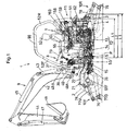
Fig. 1 is a side view partially in section showing an embodiment of the invention in its entirety, -
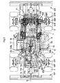
Fig. 2 is a plan view partially in section showing the embodiment, -
Fig. 3 is a plan view partially in section showing a center portion of the embodiment, -
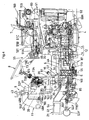
Fig. 4 is a side view partially in section showing the center portion -
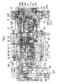
Fig. 5 is a front view partially in section showing the embodiment, -
Fig. 6 is an overall front perspective view, -
Fig. 7 is an overall rear perspective view, -
Fig. 8 is a central section view, -
Fig. 9 is a plan view of a vehicle frame, -
Fig. 10 is a side view of the vehicle frame -
Fig. 11 is a rear view in section of a rear suspension unit, -
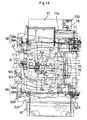
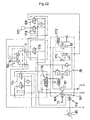
Fig. 12 is a plan view in section of a transmission, -
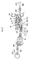
Fig. 13 is a side view in section showing a traveling transmission system, -
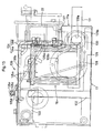
Fig. 14 is a plan view showing a center portion of a traveling body, -
Fig. 15 is a front view of a work oil tank, -
Fig. 16 is a section view showing a swivel joint in its entirety, -
Fig. 17 is a section view showing a lower portion of the swivel joint, -
Fig. 18 is a perspective view showing a front portion of an upper structure, -
Fig. 19 is a rear view of a steering unit, -
Fig. 20 a side view of the steering unit, -
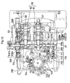
Fig. 21 is a hydraulic circuit diagram of the entire work vehicle, and -
Fig. 22 is a hydraulic circuit diagram of the transmission. - Embodiments of the invention will be described with reference to the accompanying drawings.
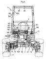
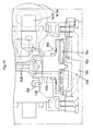
- Referring to
Figs. 1 through 7 , awheeled work vehicle 1 includes, as its major components, a 4-wheeledtype traveling body 4 having front andrear wheels upper structure 11 having aswivel base 6 mounted on the travelingbody 4 via a swivel shaft (swivel axis) 5 and having also a driver'sseat 7 and asteering unit 8 both mounted on thebase 6, a ground-work implement 9 mounted on theswivel base 6, and front and rear dozers (acting also as stabilizers) 10F, 10R attached to front and rear portions of the travelingbody 4. - The traveling
body 4 includes a travelingdrive unit 12 having anengine 13 and apower transmission mechanism 14, avehicle frame 21, frontwheel suspension units 61F suspending thefront wheels 2 therefrom, rearwheel suspension units 61R suspending therear wheels 3 therefrom, and so on. The travelingbody 4 mounts theengine 13 at a rear portion thereof and mountsselector valves 54 for hydraulic system at a front portion thereof. In theupper structure 11, thesteering unit 8 is disposed forwardly of the driver'sseat 7. - As shown in
Figs. 2 ,4 ,5 ,8-10 , thevehicle frame 21, which presents a ladder-like shape in a plan view, includes a pair of right and left side frames 22 formed of angular pipes, front and rear plate-like frames bearing support member 25 to which a swivel bearing 36 is attached, the bearingsupport member 25 interconnecting intermediate portions of the opposed side frames and a plurality of other connecting members for connecting the front and rear portions of the opposed side frames. Further, the right and left side frames 22 mounts, at their intermediate to rear portions thereof, theengine 13 and thepower transmission mechanism 14 and mounts also aradiator 62 at rear portions thereof. Thepower transmission mechanism 14 is attached to theengine 13 and/or the right and left side frames 22. - Here, according to essential features of the present invention, as may be apparent from
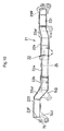
Fig.1 andFig. 10 , thevehicle frame 21 include an intermediate frame portion located between the front andrear wheels wheel suspension units 61F for thefront wheels 2 whereas the rear frame portion mounts the rearwheel suspension units 61R for therear wheels 3. To this end, as may be apparent fromFig. 9 andFig. 10 , thevehicle frame 21 includes right and left side frames 22, afront frame 23F acting as a cross beam for interconnecting the right and left side frames 22 at front portions thereof with a predetermined distance therebetween and arear frame 23R acting as a further cross beam for interconnecting the right and left side frames 22 at rear portions thereof with a predetermined distance therebetween. Further, each of the two side frames 22 includes an a horizontalintermediate portion 22a located at an intermediate portion of the side frame, a horizontalrear portion 22r located at a rear portion of the side frame and having a higher ground level than theintermediate portion 22a, ahorizontal front portion 22f located at a front portion of the side frame and having a higher ground level than theintermediate portion 22, a rear transition portion 22ar connecting a rear end of theintermediate portion 22 and therear portion 22r, and a front transition portion 22af connecting a front end of theintermediate portion 22 and thefront portion 22f. Further, a distance between the right and leftintermediate portions 22a is greater than a distance between the opposedfront portions 22f and greater also than a distance between the opposedrear portions 22r. Further, thefront portions 22f have a higher ground level than therear portions 22r. - Namely, in the side view of the
vehicle frame 21, in each of the right and left side frames 22, theintermediate portion 22a is disposed downwardly of theswivel base 6 is located at the lowermost level, therear portion 22r raised in the fore/aft direction from thisintermediate portion 22a is located at a higher level and thefront portion 22f raised also from theintermediate portion 22a is located at an even higher level, so that thevehicle frame 21 allows attachment of the front and rear wheel suspension units under the front and rear portions thereof, respectively. - More particularly, the top face of the
intermediate portion 22a which is overlapped with theswivel base 6 mounted on thevehicle frame 21 is set lower than the top faces of the front and rear portions and the bottom faces of the front and rear portions are set higher than the bottom face of theintermediate portion 22a. With these arrangements, compared with a conventional vehicle frame which is formed flat entirely, theswivel base 6 can be disposed at a lower level, thus reducing a ground-level difference between theswivel base 6 and the front andrear suspension units - Further, in the plan view of the
vehicle frame 21, in the right and left side frames 22,the opposedintermediate portions 22a overlapped with theswivel base 6 are formed wider in the right/left direction than the opposed front portions and also the opposed rear portions. In addition, eachside frame 22 is bent at two positions in the fore/aft direction and then extends outward therefrom, so that the side frame presents a trapezoidal shape. - In the right and left side frames 22, the opposed
intermediate portions 22a form the distance, i.e. right/left-wise width, greater than that of the front portions and that of the rear portions as described above. And, to top and bottom faces of border portions between theintermediate portion 22a and the front and rear portions, there are attached reinforcingplates 22b. - In the ladder-like shaped
vehicle frame 21 described above, theintermediate portions 22a extend outward in the right/left directions from the front and rear portions and also the right and left sides of the frame are located radially inside the outer periphery of theswivel base 6 and also radially outside the outer periphery of theswivel bearing 36. So that, the swivel bearing 36 is confined within and vertically overlapped with the area delimited between the opposedintermediate portions 22a of thevehicle frame 21, thereby to allow for the lower-level mounting of theswivel base 6. - The
vehicle frame 21 thus constructed provides a rigid and strong structure capable of sufficiently supporting the upper load as well as withstanding load in the fore/aft direction. And, as theintermediate portions 22a are formed lower than the front and rear portions, the swivel bearing 36 and theswivel base 6 can be disposed at lower positions than the upper ends of the front andrear wheels - As may be seen from
Figs. 2 and3 , each frontwheel suspension unit 61F includes a cylindrical hollow front axle case (differential case) 63F and a front wheeldifferential unit 64F accommodated therein. The right-to-left center of thisfront axle case 63F is supported to the front lower portion of thevehicle frame 21 via acenter pin 65F extending in the fore-and-aft direction, thereby to allow the right and left ends of the unit to be vertically pivotable. Further, at a right or left end of thefront axle case 63F, there is provided abevel gear case 66F for supporting a king pin, and to thisbevel gear case 66F, there is provided a frontwheel transmission case 67F to be pivotable about the king pin, and thefront wheel 2 is mounted on anaxle 68F supported to this frontwheel transmission case 67F. With this, the right and leftfront wheels 2 are steerable via the respective frontwheel transmission cases 67F by a steering means 69. - Like the front
wheel suspension unit 61F described above, as shown inFigs. 3 and11 , each rearwheel suspension unit 61R includes a cylindrical hollowrear axle case 63R and a rear wheeldifferential unit 64R accommodated therein. To the right or left end of therear axle case 63R, there is provided abevel gear case 66R supporting aking pin 66a. Thisbevel gear case 66R includes a rearwheel transmission case 67R to be pivotable about theking pin 66a and therear wheel 3 is mounted on anaxle 68R supported to this rearwheel transmission case 67R. With this, the right and leftrear wheels 3 are steerable via the respective rearwheel transmission cases 67R by the rear steering means 69. - Like the front
wheel suspension unit 61F, the rearwheel suspension unit 61R also may be constructed such that the right-to-left center of therear axle case 63R is supported for allowing, via a center pin provided at a rear lower portion of thevehicle frame 21 extending in the fore-and-aft direction, the right and left ends of the unit to be vertically pivotable. In this embodiment, however, therear axle case 63R is fixed to thevehicle frame 21. - Referring to the rear
wheel suspension unit 61R, therear axle case 63R comprises right and left separate members which are coupled via aflange portion 93a in abutment with each other. One separate member accommodates therein a rear wheeldifferential unit 64R inserted from the end therefor where theflange portion 93a is formed and supports abevel pinion shaft 86R inserted therein for receiving power from thepower transmission mechanism 14. - In one
rear axle case 63R, a pair ofbearings 95B, 95c are supported within acylindrical hole 95a. Thesebearings differential case 95d. Thisdifferential case 95d mounts at an end thereof a differentiallarge gear 95e meshing with thebevel pinion shaft 86R. This differentiallarge gear 95e is supported by the onebearing 95b also. From thedifferential case 95d, adifferential yoke shaft 70 extends outwards to the right and to the left. - Each of the right and left
rear axle cases 63R includes, at outer ends thereof, brake portions 63a and adifferential lock portion 63b formed more inward than the brake portions 63a. At an outer end of each of the right and left brake portions 63a, thebevel gear case 66R is secured and to thisbevel gear case 66R, there is attached the rearwheel transmission case 67R supporting therear wheel 3 via theaxle 68R. - The
differential yoke shaft 70 extends through from the rear wheeldifferential unit 64R into the right and leftbevel gear cases 66R. Between thisdifferential yoke shaft 70 and the brake portions 63a, there is disposed a hydraulic brake mechanism A and between thedifferential yoke shaft 70 and thedifferential lock portion 63b, there is disposed a hydraulicdifferential lock mechanism 177. - The
bevel gear case 66R is connected to the outer end of the brake portion 63a through a faucet-like joint and supports via a bearing abevel gear 96a fitted on the outer end of thedifferential yoke shaft 70 and supports also abevel gear 96b fitted on the upper end of theking pin 66a and meshed with thebevel gear 96a. - The rear
wheel transmission case 67R is supported to a lower potion of thebevel gear case 66R via a pair ofbearings 96c to be pivotable about theking pin 66a and its upper portion too is pivotally supported to an upper portion of thebevel gear case 66R. - This rear
wheel transmission case 67R supports theaxle 68R and supports also thebevel gear 96d fitted on a lower portion of theking pin 66a for meshing with thebevel gear 96e fitted on theaxle 68R. - The
bevel gear case 66R and the rearwheel transmission case 67R together constitute a final reduction case mounted on the outer end of each of the right and leftrear axle cases 63R and the two sets ofbevel gears - The brake portion 63a houses therein a piston A2 for pushing a disc A1 of the brake mechanism A into an engaging
portion 66b of thebevel gear case 66R. In operation, as the piston A2 is pushed by an oil pressure externally supplied, the disc A1 is pushed into the engagingportion 66b of the bevel gear case 66, thereby to brake thedifferential yoke shaft 70. Incidentally, the disc A1 may be directly pushed into the engagingportion 66b of thebevel gear case 66R. But, an abutment plate may be provided or the piston A2 may be disposed on the side of the engagingportion 66b so that the disc A1 is pushed toward therear axle case 63R. - The
differential lock mechanism 177 includes an engagingmember 177a fixed to thedifferential case 95d, a movable engagingmember 177b provided on thedifferential yoke shaft 70 to be rotatable therewith and movable relative thereto, ahydraulic means 177c for pushing the movable engagingmember 177b toward the engagingmember 177a for engagement therewith and an urging means 177d for urging the movable engagingmember 177b away from the engagingmember 177a. Hence, upon engagement between the movable engagingmember 177b and the engagingmember 177a, thedifferential case 95d and thedifferential yoke shaft 70 are rotated in unison. - As the
differential lock mechanism 177 has a relatively small outer diameter, thedifferential lock portion 63b of therear axle case 63R projects radially inward and is smaller than thecylindrical hole 96b. For this reason, the rear wheeldifferential unit 64R and the brake mechanism A can be fixed in position in one direction. - The other separate member does not support the rear wheel
differential unit 64R or thebevel pinion shaft 86R. However, the brake mechanism A of the brake portion 63a and thedifferential lock mechanism 177 of thedifferential lock portion 63b of the other separate member are substantially same as those of the one separate member described above. - As shown in
Fig. 3 , the right and leftrear axle cases 63R include cylinder attaching portions 63a projecting in opposition to each other and ahydraulic steering cylinder 71 of the steering means 69 is attached to thesecylinder attaching portions 63c. The connection between the right and leftrear axle cases 63R functions also as the attachment of thecylinder 71. - The steering means 69 includes the hydraulic cylinder (power steering cylinder) 71 provided in the
rear axle case 63R and atie rod 72 interconnecting opposed ends of apiston rod 71a of thehydraulic cylinder 71 and the right and left rearwheel transmission cases 67R, so that with a movement of thepiston rod 71a to the right or left the steering means 69 pivots the right and left rear wheel transmission cases 67 about theking pin 66a, thereby to steer therear wheels 3. - To the left rear
wheel transmission case 67R, there is fixed anarm 120 and afirst coupling rod 121 is connected to thisarm 120.Numeral 122 denotes a moving body having an intermediate portion thereof pivotally supported via a vertical shaft to theintermediate portion 22a of theleft side frame 22. To opposed ends of this movingbody 122, there are connected one end of thefirst coupling rod 121 and one end of asecond coupling rod 123, respectively. The other end of thesecond coupling rod 123 is connected to anarm 124 provided in the left frontwheel transmission case 67F for thefront wheel 2.Knuckle arms 125 of the right and left frontwheel transmission cases 67F are interconnected via atie rod 126. - With the steering means 69 in operation, when the
rear wheels 3 are steered by the actuation of thehydraulic cylinder 71, thefront wheels 2 are also steered through the movingbody 122 and the first andsecond coupling rods front wheels 2 and therear wheels 3 are steered in opposite directions. Instead, the front andrear wheels - The traveling
body 4 is a two-shaft, four-wheel drive construction in which the power is transmitted from the travelingdrive unit 12 to both the front wheeldifferential unit 64F and the rear wheeldifferential unit 64R and is also a four-wheel steering type construction in which the front andrear wheels single steering wheel 73. - However, the traveling
body 4 may alternatively be constructed such that either thefront wheels 2 or therear wheels 3 alone are provided as the drive and steerable wheels with the other as driven and non-steerable, i.e. straight traveling, wheels. Further alternatively, the structure may be constructed such that either thefront wheels 2 or therear wheels 3 alone are constantly driven and steered and the other are driven and steered only when needed. - Further, in the illustrated embodiment, the front and
rear wheels - As shown in
Figs. 1 ,2 ,6 and7 , at the front and rear portions (front andrear frames body 4, in order to mountrespective dozers upper cylinder support 75 project forwardly. - Each
dozer blade 76, a pair of right and leftarms 77U attached to an upper portion of the rear face of theblade 76 and pivotally supported to the upper arm supports 74U to be liftable about horizontal axes, and anoperational cylinder 78 supported to thecylinder support 75 for lifting the dozer 10 up and down so as to bring theblade 76 into contact with the ground surface or insert it into the ground. - This
dozer body 4. In this embodiment, however, two of them are provided at the front and the rear portions so that the dozers may lift the travelingbody 4 up off the ground during a work. - As may be seen from
Figs. 1 ,2 ,5-8 ,14 and15 , on right and left sides (side frames 22) of the travelingbody 4 and between the front andrear wheels fuel tank 16 on one side (left side) and there are disposed awork oil tank 17 and abattery 18 behind it on the other side (right side). The right and left arrangement of these tanks, i.e. thefuel tank 16 and thework oil tank 17 may be reversed. In either case, with this right and left distribution of the tanks, the right and left weight balance of the travelingbody 4 is improved and also the space between the front andrear wheels - As described above, the
fuel tank 16 and thework oil tank 17 plus thebattery 18 are arranged in the right and left distribution on thevehicle frame 21. Thework oil tank 17 is detachably mounted on theright side frame 22 and has a substantially L-like shape in front view and includes anextension portion 17a extending under theright side frame 22. Within thisextension portion 17a, anoil filter 130 is disposed and there is formed an L-shaped (in plan view)recess 17b for disposing thebattery 18. - The
recess 17b is formed at a rear and right-to-left wise inner portion of thework oil tank 17. Then, as thebattery 18 is disposed therein, thebattery 18 is covered by thework oil tank 17 from the outer side and the front side. - At a front lower portion of the
work oil tank 17, there is formed a keyhole-shapedopening 128 comprising large andsmall holes 128a, 128b connected in series. Acover member 129 for closing thisopening 128 too has a keyhole-like shape Thiscover member 129 defines a small-hole corresponding portion 129a to which the oil filter (suction filter) 130 and asuction pipe 131 communicating therewith are connected. Thesuction pipe 131 extends under theside frame 22 to be connected with various valves. - The
oil filter 130 as being attached to thecover member 129 is inserted from thelarge hole 128b to the small hole 128a, thereby to allow attachment of thecover member 129 in correspondence with the keyhole opening. In this way, maintenance operation is facilitated through the facilitation of insertion of theoil filter 130 into theopening 128. -
Numeral 132 denotes an outlet pipe which extends from apump 133 of thework oil tank 17 and under thebattery 18 and theside frame 22 to be eventually connected with the hydraulic pump for theengine 13. - On the top of the
right side frame 22, there are provided erect a plurality of retainingpins 134a for allowing temporary retention of thework oil tank 17 by these retainingpins 134a. These retainingpins 134a and apertured retainingmembers 134b provided in thework oil tank 17 to be retained thereto together constitute tank temporary fixing means 134. - Further, the
work oil tank 17 temporarily fixed by the temporary fixing means 134 can then be fixed permanently by a permanent attachingmeans 136. This permanent fixing means 136 includes arod 135d extending in the fore-aft direction and retained by a substantially L-shaped (in front view) retainedmember 135e fixed on the top face of thework oil tank 17 and a retainingmember 135a to be fastened to opposed ends of therod 135d by means of nuts 135e. Then, the lower end of the retainingmember 135a is hooked to the apertured retaining member 139a attached to theright side frame 22 and abracket 139b and then thenuts 135e are fastened, whereby thework oil tank 17 is drawn toward theright side frame 22. With this, the permanent attachment is completed. - The permanent attaching
means 136 may alternatively be constructed such that thework oil tank 17 is fixed to theright side frame 22 by means of fastening members such as bolts. - Between the bottom face of the
right side frame 22 and theextension portion 17a, there is provided acushion member 137 formed of e.g. rubber, so that thework oil tank 17 may be supported with its top face being oriented substantially horizontal. - The
work oil tank 17, as denoted with two-dot lines inFig. 8 , is covered with acover 138 having an outer face and an upper face which are substantially reversed-L shaped in the front view. Thiscover 138 is formed of a metal plate or plastic and is attached via e.g. a mount to the front and rear portions of thework oil tank 17 bybrackets 139b fixed to theright side frame 22. The upper horizontal portion of thiscover 138 provides astep portion 138A. - The
fuel tank 16 is formed of plastic or plate metal and is fixed to the outer face of theleft side frame 22. - More particularly, to the outer face of the
left side frame 22, there are attached a pair of front andrear brackets 190 extending outward in the right and left directions, and to and between these front andrear brackets 190, thefuel tank 16 is attached. - This
fuel tank 16, like thework oil tank 17 described above, may have a substantially L-shape (in plan view) having an extension portion extending under theside frame 22, so that the tank may be attached via a tank temporary retaining means and tank permanent attaching means. - Further, like the
work oil tank 17, the top face and the outer face of thefuel tank 16 are covered with acover 191. Thiscover 191 is attached to thebrackets 190 viamounts 190a. The top horizontal portion of thiscover 191 provides astep portion 191A. - Incidentally, the
covers tanks tanks - As shown in
Figs. 1-4 ,6 ,7 ,12 and13 , the travelingbody 4 has a portion thereof downwardly of theswivel base 6 provided as aflat portion 4A and a further portion thereof rearwardly of theswivel base 6 as a raised portion 4B. To this raised portion 4B, anengine hood 80 is detachably attached to be opened and closed. - Within the
engine hood 80 attached to the raised portion 4B of the travelingbody 4, theengine 13 is mounted and in theflat portion 4A thereof, thepower transmission mechanism 14 is mounted. And, theswivel base 6 is disposed upwardly of theflat portion 4A housing thepower transmission mechanism 14. Theengine 13 projects downwardly of theswivel base 6. - The
engine 13 may be disposed with the axis of itscrank shaft 13A being oriented along the right and left direction. In this case, however, theengine 13 is disposed along the fore and aft direction, with the right-and-leftcenter 13S (seeFig. 3 ) thereof being substantially aligned with or slightly offset to one side (left side) from the right-and-left center of the vehicle frame 21 (extending through acenter 5S of the swivel shaft 5). - The
radiator 62 disposed rearwardly of theengine 13 may alternatively be disposed at the right-and-left center of thevehicle frame 21. In this case, however, theradiator 62 is disposed with offset to the same side as theengine 13. - The
power transmission mechanism 14 disposed at theflat portion 4A can be a mechanical transmission mechanism. In this case, however, thismechanism 14 is provided as combination of a hydrostatic transmission (HST) 26 including apump 81 and amotor 82, and areduction device 87. As shown inFigs. 3 ,4 ,12 and13 , atransmission case 83 for thishydrostatic transmission 26 supports aninput shaft 27 for thepump 81 for receiving the power from theengine 13 and anoutput shaft 28 of themotor 82. And, these shafts are respectively aligned substantially with the fore and aft direction in the plan view. Thetransmission case 83 of thetransmission 26 and front andrear cases reduction device 38 are assembled together and theinput shaft 27 and theoutput shaft 28 are disposed with slightly forward-downward inclination in the side view thereof. - The
reduction device 87 accommodates, inside the front andrear cases rear cases front case 87A includes acharge pump 109 and ahydraulic clutch 110 controlled by thischarge pump 109. - The
input shaft 27 projects forwardly and rearwardly from thetransmission case 83, with its rear portion being coupled via a flywheel to the crankshaft 13A and its front portion is supported to the rear case 87b of thereduction device 87 and mounts agear 107A of the reduction gear set 107 and is operable for driving thecharge pump 109. - The
gear 107A of the reduction gear set 107 is meshed with agear 107B and thisgear 107B is mounted on aclutch input shaft 111 of thehydraulic clutch 110. Between thisclutch input shaft 111 and aclutch output shaft 112 of thehydraulic clutch 110, there is provided a clutch means 113 which can be engaged/disengaged by the pressure oil fed from thecharge pump 109. - The
clutch output shaft 112 drives, via a universal joint shaft, thehydraulic pump 85 for feeding work oil of a large load. - The
charge pump 109 is comprised of e.g. a trochoid pump. When theengine 13 is driven, thispump 109 feeds the pressure oil of a predetermined pressure to the clutch means 113 to keep it engaged. When theengine 13 is stopped, thecharge pump 109 is also stopped, thereby to disengage the clutch means 113. Accordingly, for a start-up of theengine 13, this may be done without applying the load from thehydraulic pump 85 to theclutch output shaft 112. Hence, the start-up load can be reduced advantageously. - The
output shaft 28 of themotor 82 mounts agear 108A of the reduction gear set 108. Thisgear 108A is meshed with a gear 108B mounted on a propellingshaft 114. The propellingshaft 114 projects forwardly and rearwardly of the front andrear cases reduction device 87 to be connected respectively via front and rear universaljoint shafts pinion shafts differential unit 64F and the reardifferential unit 64R. - In this way, by using the front and rear universal
joint shafts rear wheels bevel pinion shafts center pin 65, or the propellingshaft 114 is inclined downward forwardly, the power transmission to the front and reardifferential units 64 is still allowed and the vertical pivotal movements of thefront axle cases 63F are allowed also. - In
Figs. 1 through 7 , the travelingbody 4 mounts thereon the swivel bearing 36 for swivelably supporting theswivel base 6, aring gear 88 attached along the inner periphery of the swivel bearing 36, adrive pinion 89 meshing with thisring gear 88, and ahydraulic swivel motor 15 for driving thedrive pinion 89 for swiveling theswivel base 6. - The
swivel shaft 5 mounted at thecenter 5S of the swivel bearing 36 is constructed as a swivel joint, so that connections of work oil passages connecting thehydraulic pump 85 to the ground-work implement 9, pilot oil passages connecting the manipulating unit and selector valves, electric cables interconnecting thesteering unit 8 and the travelingdrive unit 12 and so on can be carried out even during the swiveling movement of theswivel base 6. - The above-described components including the
swivel motor 15, the universal joint shafts 29, and thehydraulic pump 85 constitute some parts of thepower transmission mechanism 14 of the travelingdrive unit 12. And, these components are disposed at a level lower than the top face of thevehicle frame 21 and higher than the bottom end of theengine 13. in a compact manner not only in the vertical direction, but also in the fore-and-aft and right-and-left directions. - The components including the
swivel base 6, the driver'sseat 7 disposed at the rear upper portion of theswivel base 6 of theswivel shaft 5, thesteering unit 8 disposed at the front portion of theswivel base 6 forwardly of the driver'sseat 7, the manipulatingunit 55 disclosed around the driver'sseat 7 for manipulating the ground-work implement 9 and so on together constitute theupper structure 11. - The
center 5S of theswivel shaft 5 is slightly offset to the forward side from the center P of the axes of the front andrear wheels swivel shaft 5, the operator'sseat 7 is disposed on the rear side of theswivel base 6 and thesteering unit 8 and the ground-work implement 9 are disposed on the forward side thereof, respectively. The front end of theupper structure 11 is constructed as thesteering unit 8 and the rear portion thereof is constructed as the driver'sseat 7, and ahydraulic control valve 56 of the manipulatingunit 55 is disposed rearwardly of the driver'sseat 7. - In the
upper structure 11, the swivel bearing 36 and theswivel base 6 are disposed lower than the upper end of theengine 13 disposed at the rear portion of the travelingbody 4, and of the swivel bearing 36 and theswivel base 6, at least the swivel baring 36 is disposed at a position between the front andrear wheels rear wheels - In its plan view, the
swivel base 6 is flat at its front portion and is substantially circular at its rear and right and left side portions. The rear portion is disposed adjacent theengine 13. When thebase 6 is oriented forwardly, the front portion is substantially aligned with the rear ends of the right and leftfront wheels 2. When thebase 6 is swiveled, its outer periphery becomes overlapped in the fore-and-aft direction with the rear ends of the right and leftfront wheels 2. And, thisswivel base 6 projects sideways to the right and left from thevehicle frame 21 to be overlapped in the right and left direction with thefuel tank 16 and thework oil tank 17, respectively. - That is, the
swivel base 6 is formed such that it has a progressively larger area defined by three points of theengine 13 disposed substantially right-and-left center and the pair offront wheels 2 disposed apart therefrom on the right and left sides. Or, after securing a necessary area for theswivel base 6, the fore-and-aft dimension and the right-and-left dimension of the travelingbody 4 are set as compact as possible. - And, since the traveling
body 4 mounts thereon such components as theengine 13, thefuel tank 16, thework oil tank 17, theselector valves 54 etc., this travelingbody 4 has a significant weight, whereby the weight of theupper structure 11 is reduced correspondingly and its fore-and-aft and right-and-left dimensions may also be small. - With the above-described construction, relative to the weight of the traveling
body 4 having the front andrear wheels swivel base 6, the driver'sseat 7 on theswivel base 6, thesteering unit 8 and the ground-work implement 9, or the total weight of at least theswivel base 6 and the driver'sseat 7 and thesteering unit 8 mounted thereon may be smaller. - Further, the arrangement of the
power transmission mechanism 14 around theswivel shaft 5 and also the above-described triangular arrangement of theengine 13, thefuel tank 16 and thework oil tank 17, etc. all help improve the weight balance around theswivel shaft 5. Further, as theengine 13 is disposed at the rear portion of the travelingbody 4, theselector valves 54 are disposed at the front portion and thework oil tank 17 and thefuel tank 16 are disposed on the right and left sides thereof, the weight balance in all directions is improved. - The gravity center Q of the
work vehicle 1 is located slightly forwardly of thecenter 5S of theswivel shaft 5 and adjacent the rear end of thehydraulic pump 85 in the fore/aft direction and is located also adjacent the top faces of theswivel base 6 and the swivel bearing 36 in the right/left direction. Further, in the right/left direction, this gravity center Q is located at a position slightly offset to the right relative thecenter 5S and overlapped with theswivel motor 14. - In this
work vehicle 1, in order to improve the traveling stability, the working stability, etc. by lowering the gravity center Q of the travelingbody 4, theengine 13 is disposed on the travelingbody 4. Further, in order to dispose theswivel base 6 at a lowest possible position in spite of theengine 13 being mounted on the travelingbody 4, theengine 14 is mounted at the rear portion of the travelingbody 4. Further, by disposing thepower transmission mechanism 14 forwardly of theengine 13, the vertical dimension of the travelingbody 4 under theswivel base 6 is reduced advantageously. - A distance L1 measured from the
center 5S of theswivel shaft 5 and the rear end of theupper structure 11 is set to be within a distance L2 measured from thecenter 5S of theswivel shaft 5 and the rear ends of therear wheels 3 or at least within a distance L3 measured from thecenter 5S of theswivel shaft 5 and the rear end of the travelingbody 4. With this, when theupper structure 11 is swiveled, this will not hit an object which may be present rearwardly. - As shown in
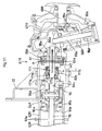
Figs. 8 ,12 ,14 ,16 and17 , the swivel joint (swivel shaft) 5 includes acylindrical member 141 fixed to thevehicle frame 21 of the travelingbody 4 via abracket 140, and acenter shaft 143 rotatably mounted inside thecylindrical portion 141 and non-rotatably attached to theswivel base 6 via astopper plate 142. At an upper portion of thiscenter shaft 143, there is provided an oil passage connectingannular member 144 connected to an actuator. Downwardly of thecylindrical member 141 and thecenter shaft 143, there is provided (electric) current-carryingmeans 145. - The
cylindrical member 141 has a large surface area. Hence, various pipes are connected thereto with appropriate peripheral and axial spaces therebetween. More particularly, from the top to the bottom of thecylindrical member 141, thismember 141 defines apilot connection opening 141j, ahydrostatic transmission 26connection opening 141e, an oil pressuresignal connection opening 141n, abrake connection opening 141h, apower steering cylinder 71 left connection opening 141c, apower steering cylinder 71 right connection opening 141d, adozer actuator cylinder 78 elevating connection opening 141f, adozer actuator cylinder 78 lowering connection opening 141b, aswivel motor 15 right swiveling connection opening 141i, aswivel motor 15 left swiveling connection opening 141g, an auxiliary hydraulic motor connection opening 141k, amain connection opening 141m, adrain 141t, etc. - Inside the
center shaft 143, there is formed an oil passage communicating the respective connection openings of thecylindrical member 141 to the oil passage connectingannular member 144 via radial oil passages and axial oil passages. Hence, to the oil passage connectingannular member 144, there are connected pipes communicating with these oil passages. Incidentally, thecenter shaft 143 and the oil passage connectingannular member 144 may be formed integrally. - Although the oil passage connecting
annular member 144 may define various connection openings to be connected with pipes, this will require an area for defining these connection openings as large as that of thecylindrical member 141. For this reason, in the instant embodiment, the pipes are integrally welded in the form of a multi-directional piping arrangement on the surface of the oil passage connectingannular member 144. - This oil passage connecting
annular member 144 projects upward from the swivel bearing 36 into theswivel base 6. In particular, theswivel base 6 includes right and left raisedribs 35, so it is difficult for themulti-directional piping arrangement 146 to project from the oil passage connectingannular member 144 in the right/left directions. For this reason, thepiping arrangement 146 is bent in the middle thereof to be oriented in the fore-aft direction. - The
piping arrangement 146 is disposed lower than the top face of the raisedribs 35 and theswivel base 6 defines anopening 6a for introducing a hose connecting between the pipingarrangement 146 and theupper structure 11. - The
center shaft 143 defines a throughhole 147 along the axis thereof, into which aharness 148 is inserted. The bottom face of thecenter shaft 143 defines anengaging recess 150 for engagement with acoupling 149. - To the bottom of the
cylindrical member 141, there is detachably attached ajoint cover 151 and acase member 152 is attached to an upper portion of this joint over 151 and the current-carryingmeans 145 is disposed between the case member and thejoint cover 151. - To a fixed side of the
joint cover 151 or of thecase member 152, there is fixed a stationary current-carryingmember 153 such as a brush, which comes into sliding contact with a movable current-carryingmember 154 for establishing electric connection therewith. - The movable current-carrying
member 154 is disposed under arotary shaft 155 coaxial with thecenter shaft 143 and rotatably supported to thecase member 152. And, thecoupling 149 is fitted to an upper portion of thisrotary shaft 155 projecting from thecase member 152 and thiscoupling 149 is inserted into the engagingrecess 150 to be engaged with thecenter shaft 143, whereby therotary shaft 155 is rotated together with thecenter shaft 143. - The
harness 148 has its one end connected to an electric controller mounted on theswivel base 6 and the other end inserted into therotary shaft 155 to be connected with the movable current-carryingmember 154, whereby electric current supply to theengine 13 and various electromagnetic valves mounted on the travelingbody 4 is controlled via the stationary current-carryingmember 153. - The current-carrying
means 145 is used mainly for carrying electric current for control signals, but may be used for supplying electric power for driving motors. - On the
swivel base 6, an implementsupport unit 37 is provided erect at a front portion and arear wall portion 34 is provided erect at a rear portion of the base. And, the right and left raisedribs 35 provided erect at the intermediate portion of thebase 6 connect the implementsupport unit 37 with therear wall portion 34, whereby theentire swivel base 6 is formed as a strong three-dimensional structure. - Referring to
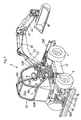
Fig. 1 andFigs. 4-7 , there is provided a driver'sseat mounting frame 51 which extends rearward from the upper portion of therear wall portion 34 of theswivel base 6 and projects over and above theengine 13. To form this driver'sseat mounting frame 51, a pair of right and lefttransverse pipe members 51B are secured to an attachingplate 51A secured to the top face of therear wall portion 34 andvertical pipe members 51C project rearward from the right and lefttransverse members 51B and the right and leftvertical members 51C are connected via a plurality of connectingmembers 51D. Then, this driver'sseat mounting frame 51 mounts the driver'sseat 7 at a front portion thereof and also mounts at rear portions thereof thehydraulic control valve 56 of thecontroller 55, anelectric generator 159 having an auxiliaryhydraulic motor 158 and abattery 160. - At an upper portion of the implement
support unit 37 of theswivel base 6, there are provided a pair of right and leftsupport members 38. Thissupport member 58 includes a hooked-shapedmember 58A and a horizontaltransverse pipe member 58B projecting from themember 58A. The hookedmembers 58A are bolt-fixed to the implementsupport unit 37 and thetransverse members 58B form a pair of right and left ROPS support portions. - The right and left
transverse members 51B of the driver'sseat mounting frame 51 also constitute the ROPS support portions. To thetransverse member 51B and thetransverse member 58B disposed one in front of the other, front andrear struts ROPS 53 are connected and supported. - Referring more particularly to the
ROPS 53, its portion from therear strut 52R to theupper portion 52U is formed by bending a single pipe member in the substantially U-shape and theupper portion 52U and the upper end of thefront strut 52F are connected to each other. Then, these right and leftROPS 53 are connected via a plurality of connectingrods 60 and acanopy 90 is attached to theupper portion 52U for sun beam shading. - To the bottom ends of the front and
rear struts members members transverse members ROPS 63 may be attached to theswivel base 6. - Incidentally, the connecting portions may be connected with the
transverse members - Each of the right and left
rear struts 52R is bent in an L-like shape, so that the strut extends from therear wall portion 34 of theswivel base 6 to a position rearward and upward of the driver'sseat 7 and then extends upward from its intermediate portion, whereby this strut projects upwardly of theengine 13 together with the driver'sseat mounting frame 51. - Accordingly, the driver's
seat mounting frame 51 and the operator'sseat 7 are disposed at a position higher than theengine 13, so that theswivel base 6 when being swiveled, can pass above theengine 13, that is, pass above the raised portion 4B which forms the highest portion of the travelingbody 4. - With the above-described arrangements of mounting the
engine 13 on the rear portion of the travelingbody 4 and disposing the driver'sseat 7 at the position projecting rearwardly and upwardly from theswivel base 6, on theswivel base 6, the driver'sseat 7 is disposed on the rear portion thereof and also thesteering unit 8 is disposed on the front portion thereof. Consequently, the weight of theupper structure 11 is reduced significantly and its fore-and-aft dimension may be the necessity minimum dimension. - And, the area of the
swivel base 6 forwardly of the operator'sseat 7 may be efficiently utilized as a space reserved for the driver and theswivel base 6 may be disposed within a limited area and at a low position, so that theentire work vehicle 1 may be formed compact in the fore-and-aft direction, the right-and-left direction and the vertical direction as well. - The driver's
seat mounting frame 51 supports right and left lever manipulating means 55L, 55R of manipulatingunits 55 disposed on the right and left sides of the operator'sseat 7 for manipulating the ground-work implement. These right and leftlever manipulating units boom cylinder 43, anarm cylinder 45, an implementcylinder 47 etc. of the ground-work implement 9 to be described later and theswivel motor 15, etc. - Further on the right and left side of the driver's
seat 7, there are disposed a manipulatinglever 181 for theswing cylinder 41 of the ground-work implement 9, a manipulatinglever 182 for atilt cylinder 184 of the implement 46, and a manipulatinglever 183 for thedozer actuating cylinders 78. There are also provided other components such as ahand accelerator lever 187 for operating a governor of theengine 13 and travelinglock levers 188 for operating the travelinglock valve 178. The travelinglock levers 188 are disposed on the right and left sides of the driver'sseat 7. - Rearwardly of the driver's
seat mounting frame 51 and on the right and left sides of thehydraulic control valve 56, there are disposed remote control valves for the swing, tilt and dozers to be manipulated by the manipulatinglevers - For allowing the high-speed vehicle run on the road, the
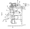
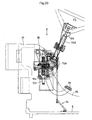
steering unit 8 includes thesteering wheel 73 and asteering controller 73A of thesteering wheel 73 and other associated components are attached to asupport member 38 mounted erect on theswivel base 6 and rearwardly of the implementsupport unit 37, so that these components may be mounted on theswivel base 6 as an assembly. - More particularly, as shown in
Figs. 18 through 20 , in addition to thesteering controller 73A, thesupport member 38 pivotally supports also a change-speed pedal 94 for operating thehydrostatic transmission 26 for change-speed, whichpedal 94 is disposed near a position where the driver's right foot is to be placed, and pivotally supports abrake pedal 91 in its vicinity. In addition, there are attached amaster cylinder 101 and anoil tank 102 for operating the brake mechanism A as well as such other components as adamper 103 for the change-speed pedal 94 and aremote control valve 104 for the HST. - Along a
handle post 73B of thesteering wheel 73, there is disposed ashuttle lever 105 for operating a forward/reverse switch valve 174. - The
swivel base 6 mounts, at its front portion, the implementsupport unit 37 which supports the ground-work implement 9 with allowing the implement 9 to be pivoted to the right and left above theswivel base 6. While thesteering wheel 73 of thesteering unit 8 is disposed at the substantially right-and-left center of the front portion (may be offset to the left) of theswivel base 6, the implementsupport unit 37 is disposed with offset to the right so as to provide better visibility of the operating condition of the ground-work implement 9. - As shown in
Figs. 1-4 and18 , the implementsupport unit 37 is disposed erect at the front portion of theswivel base 6 so as to connect the front ends of the right and left raisedribs 35 as well as to cover the front side of thesteering unit 8 and supports aswing shaft 39 provided as a vertical shaft. Thisswing shaft 39 pivotally supports aswing member 40 which is pivoted by aswing cylinder 41. Theswing member 40 pivotally supports aboom 42 and aboom cylinder 43 for lifting up/down thisboom 42 viahorizontal shafts - The
swing member 40 is pivotally supported to an upper portion of the implementsupport unit 37 and arotary shaft 163 as a vertical shaft is pivotally supported to a lower portion of the implementsupport unit 37. To thisrotary shaft 163, anupper arm 164 and alower arm 165 are secured, with theupper arm 164 being connected to theswing member 40 via alink 166 and thelower arm 165 being connected to theswing cylinder 41, so as to act as a start-up coupling means for transmitting operational force of thelower swing cylinder 41 to theupper swing member 40. - The portion of the
swing member 40 pivotally supporting thelower boom 42 projects radially from the outer periphery (outer peripheral swiveling path) of theswivel base 6. The portion of theswing member 40 pivotally supporting the base of theupper boom cylinder 43 is located substantially above theswing shaft 39 and within the outer periphery of theswivel base 6. - The implement
support unit 37 is disposed so as to be substantially confined within the outer periphery of theswivel base 6 and theunit 37 has a height so set as to allow theboom 42 and theboom cylinder 43 to pass above the highest position of the travelingbody 4. Hence, even when theboom 42 is swiveled rearward, this will not come into contact with the front portion of thehood cover 80 as long as theboom 42 assumes an upper posture than the horizontal. - That is to say, when the ground-work implement 9 on the
swivel base 6 is swiveled, this will not collide the travelingbody 4. Therefore, the vehicle can carry out a ground work with theswivel base 6 assuming the backward posture. Hence, the ground work such as an excavating work is possible over the entire movable range of the travelingbody 4. - The ground-work implement 9 includes, at the leading end of the
boom 42, anarm 44 which is vertically pivotable by anarm cylinder 45. And, at the leading end of this arm, there is provided an implement (bucket or the like) 46 which can be pivoted up and down by the implementcylinder 47. - The implement 46 has its right-to-left center portion supported to be pivotable about a fore-and-aft shaft and has right and left side portions vertically pivotable by the
tilt cylinder 184. -
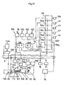
Figs. 21 and22 show the hydraulic circuit of thewheeled work vehicle 1. This circuit is divided across the swivel joint (shaft) 5 between a section for the travelingbody 4 and a further section for theupper structure 11. - The power of the
engine 13 drives thepump 81 of thetransmission 26 and drives also thecharge pump 109. This power is capable of driving also thehydraulic pump 85 via the reduction gear set 107 and thehydraulic clutch 110. - The
transmission 26 includes ashuttle valve 170 and a high/lowspeed switchover valve 171 which is operable by anelectromagnetic valve 169 to operate a swash-plate control actuator 172 of themotor 82, thereby to selectively realize a high-speed condition and a low-speed condition. - The
pump 81 is connected to aspeed actuator 173 for switching over forward/reverse drive modes and the speeds thereof. Thisspeed actuator 176 is switched over between the forward drive mode and the reverse drive mode by a forward/reverse selector valve 174 and can be controlled by aremote control valve 104 operable by the change-speed pedal 94. - The work oil from the
charge pump 109 flows through the travelinglock valve 175 to reach theremote control valve 104 and then flows from thisremote control valve 104 to either the forward driving side or the reverse driving side of the forward/reverse selector valve 174. Hence, according to an amount of the driver's stepping operation on the change-speed pedal 94, thespeed control valve 176 is operated correspondingly to control thespeed actuator 173. - The numeral 177 denotes the differential lock mechanism, which is operable to check or not check the work oil from the
charge pump 109 by a differentiallock selector valve 178, thereby to selectively provide a differential locked condition and a differential released condition. - The work oil from the
hydraulic pump 85 is fed to thehydraulic control valve 56 comprising an assembly of a plurality ofvalve elements 56a-56g. Then, the oil is supplied through therespective valve elements 56a-56g of thehydraulic control valve 56 to the respective actuators. - The left lever manipulating means 55L of the manipulating
unit 55 includes remote control valves for the arm and for swiveling for operating thearm cylinder 45 via the arm valve element 56e for a scraping or dumping operation and for operating theswivel motor 15 via theswivel valve element 56f for right or left swiveling. - The right lever manipulating means 55R includes remote control valves for the implement and the boom for operating the implement
cylinder 47 via the implementvalve element 56c for a tilting/dumping operation and operating theboom cylinder 43 via theboom valve element 56d for elevating/lowering movement. - Adjacent the left and right lever manipulating means 55L, 55R (or adjacent the steering unit 8), the three manipulating
levers lever 181 is for operating the remote control valve for the swing, i.e. for operating theswing cylinder 41 for right or left pivotal movement via theswing valve element 56b. The manipulatinglever 182 is for operating the remote control valve for the tilt, i.e. for operating thetilt cylinder 184 via thetilt valve element 56a. The manipulatinglever 183 is for operating the remote control valve for the dozers, i.e. operating thedozer operating cylinder 78 for upward/downward movement via thedozer valve element 56g. - The
hydraulic pump 85 is connected to anauxiliary pump 185. The work oil of thisauxiliary pump 185 is fed to an auxiliaryhydraulic motor 158 and then via thesteering controller 73A to the steeringhydraulic cylinder 71. - In summary, the
transmission 26, theswivel motor 15, thepumps hydraulic cylinder 71, thedozer operating cylinder 78, the travelinglock valve 175, theselector valves 54, etc. are all mounted on the travelingbody 4. Whereas, the manipulatingunit 55, the change-speed pedal 94, thesteering controller 73A, the three manipulatinglevers hydraulic motor 158, thehydraulic control valve 56, etc. are mounted on theupper structure 11. And, the work oil can be supplied/discharged vertically via theswivel joint 5. Further, via the current-carrying means 145 provided at theswivel joint 5, control signals for the electromagnetic valves for controlling thetransmission 26 and the other electromagnetic valves and the other electric devices can be transmitted from theupper structure 11 to the travelingbody 4. - The forward/
reverse switch valve 174, the travelinglock valve 175, the differentiallock switch valve 178, theelectromagnetic control valve 169, etc. are mounted as theselector valves 54 at the front portion of the travelingbody 4 and constitute the hydraulic system together with thepumps - Although it is preferred that the
wheeled work vehicle 1 include all of the respective components described above, it is also possible for the vehicle to include some of them selectively or in different combinations. - For instance, the traveling
body 4 having the front andrear wheels drive unit 12 and the dozers 10 and theswivel base 6 may be disposed at a position lower than the uppermost position of the travelingbody 4, thereby to allow the full-angle swiveling movement of thebase 6. And, on thisswivel base 6, theupper structure 11 having the driver'sseat 7 and thesteering unit 8 and the ground-work implement 9 may be mounted. With this basic construction, according to the present invention, the vehicle may include at least one of the following features (a) through (g). - (a) The
upper structure 11 and the ground-work implement 9 mounted on theswivel base 6 are adapted to be able to pass above theengine 13. - (b) In the traveling
body 4, its portion downwardly of theswivel base 6 is formed as theflat portion 4A and its portion rearwardly of theswivel base 6 is formed as the raised portion 4B. - (c) The
engine 13 is disposed at the rear portion of the travelingbody 4 and theswivel base 6 is disposed at a position lower than the upper end of theengine 13. - (d) Of the swivel bearing 36 and the
swivel base 6 at least the swivel bearing 36 is disposed between the front andrear wheels - (e) The implement
support unit 37 is disposed substantially within the outer periphery of theswivel base 6. - (f) The driver's
seat 7 is disposed to project rearward from theswivel base 6. - (g) The base portion of the ground-work implement 9 supported by the implement
support unit 37 is disposed at a position hither than the front andrear wheels engine 13. - These features may be used in various combinations also when the basic construction of the
wheeled work vehicle 1 is added with the further feature of e.g. setting the total weight of at least theswivel base 6, the driver'sseat 7, and thesteering unit 8 among theswivel base 6, the driver'sseat 7, thesteering unit 8 and the ground-work implement 9 to be less than the total weight of the travelingbody 4 including the front and rear wheels, 2, 3 or the still further feature of limiting the distance L1 from theswivel shaft 5 to the rear end of theupper structure 11 within the distance L2 from theswivel shaft 5 and therear wheel 3. - The above-described
wheeled work vehicle 1 is suitable for effecting such works as a grading operation on an inclined ground or a limited space for which the skid steering loader is generally not suited. Although this vehicle can effect such work as collecting earth while moving about, the vehicle is good at such operation of collecting earth by the hydraulic power while the vehicle is parked still on the ground. And, with exchange ofimplements 46 having different widths, this single vehicle can effect both a transporting operation and a ditch digging operation for a depth less than 1.8 m such as for laying a wire under the ground. - That is to say, the grading operations using machinery are divided roughly into the transporting operation and the grading operation. And, this
wheeled work vehicle 1 can effect with particularly high efficiency the grading operation which is a non-transporting, earth moving operation, such as for forming a slope or undulation on the ground surface or leveling the ground surface, or collecting the earth, back-filling a ditch or a hole, etc. - The front/rear, right/left and upper/lower positional relations among the respective components employed in the foregoing embodiment are best as shown in
Figs. 1-22 . However, the invention is not limited to the foregoing embodiment, but may be varied in many ways by modifying these components or combinations thereof. - For instance, in place of the four-
column type ROPS 53 employed in the foregoing embodiment, a two-column type ROPS or a cabin unit may be mounted on the vehicle. The manipulatingunit 55 may be disposed adjacent thesteering wheel 73. Further, the drive wheels may be replaced by crawlers, while providing the driven wheels as wheels. - In these manners, the invention may be embodied in any other manner as described above. Further changes or modifications will be apparent for those skilled in the art from the foregoing disclosure within the scope of the invention defined in the appended claims.
said front frame portion mounts a front-wheel suspension unit for the front wheels and said rear frame portion mounts a rear-wheel suspension unit for the rear wheels.
Claims (9)
- A wheeled work vehicle with:a traveling body (4) including front and rear wheels (2, 3), a traveling drive unit (12) having an engine (13) and a power transmission mechanism (14), a dozer unit disposed at least at a front portion of front and rear portions of the body, a fuel tank (16), a work oil tank (17), and a vehicle frame (21) mounting said members of the traveling body (4);a swivel base (6) disposed upwardly of the traveling body (4) and mounted via a swivel bearing (36) on the traveling body (4) to be swivelable for full-angle swiveling movement relative thereto;a driver's seat (7) mounted at a rear portion of the swivel base (6);a steering unit (8) disposed forwardly of the driver's seat (7); anda ground-work implement (9) supported on an implement support unit (37) disposed erect on a front portion of the swivel base (6) to be pivotable in the right/left direction;characterized in that
said vehicle frame (21) includes right and left side frames (22), a front frame (23F) acting as a cross beam for interconnecting the right and left side frames at front portions thereof with a predetermined distance therebetween and a rear frame (23R) acting as a further cross beam for interconnecting the right and left side frames at rear portions thereof with a predetermined distance therebetween;
each of the two side frames (22) includes a horizontal intermediate portion (22a) located at an intermediate portion of the side frame, a horizontal rear portion (22r) located at a rear portion of the side frame and having a higher ground level than the intermediate portion (22a), a horizontal front portion (22f) located at a front portion of the side frame and having a higher ground level than the intermediate portion (22a), a rear transition portion (22ar) connecting a rear end of the intermediate portion (22a) and the rear portion (22r), and a front transition portion (22af) connecting a front end of the intermediate portion (22a) and the front portion (22f);
said horizontal intermediate portion (22a) of the side frame is located between the front and rear wheels (2, 3) and supports said swivel bearing (36);
said horizontal front portion (22f) of the side frame mounts a front-wheel suspension unit (61F) for the front wheels (2); and
said horizontal rear portion (22r) of the side frame mounts a rear-wheel suspension unit (61R) for the rear wheels (3). - The wheeled work vehicle according to claim 1, characterized in that a distance between the right and left intermediate portions (22a) is increased relative to a distance between the front portions (22f) and also to a distance between the rear portions (22r).
- The wheeled work vehicle according to claim 1, characterized in that the front portions (22f) have a higher ground level than the rear portions (22r).
- The wheeled work vehicle according to claim 1, characterized in that the fuel tank is mounted on either one of right and left intermediate portions of the traveling body (4) and the work oil tank is mounted on the other of the right and left intermediate portions.
- The wheeled work vehicle according to claim 4, characterized in that the engine (13) is disposed at the rear portion of the traveling body (4) and the power transmission mechanism (14) is disposed at the intermediate portion of the traveling body.
- The wheeled work vehicle according to claim 1, characterized in that the implement support unit (37) pivotally supports a swing member (40) of the ground-work implement (9) via a swing shaft, the swing member pivotally supports a boom (42) via a horizontal shaft (48A, 48B) and a boom cylinder (43) for lifting up/down the boom is disposed rearwardly of the boom.
- The wheeled work vehicle according to claim 6, characterized in that a front portion of the swing member (40) projects radially outward from the swivel base (6) and is set at a height which allows passage of the boom (42) and the boom cylinder (43) above the highest position of the traveling body (4).
- The wheeled work vehicle according to claim 1, characterized in that a driver's seat mounting frame (51) disposed on the swivel base (6) includes a rear upward projecting portion projecting rearward and upward from the swivel base and the driver's seat (7) and a ground-work implement manipulating unit (55) are disposed on said rear upward projecting portion thereby to allow the driver's seat (7) to pass above the traveling body when the swivel base is swiveled.
- The wheeled work vehicle according to claim 1, characterized in that each of the driver's seat mounting frame (51) and the implement support unit (37) mounted on the swivel base (6) includes a pair of right and left attaching portions, to which front and rear ends of a ROPS having a substantially angular hooked shape are connected.
Applications Claiming Priority (2)
| Application Number | Priority Date | Filing Date | Title |
|---|---|---|---|
| JP2003292220A JP4080974B2 (en) | 2003-08-12 | 2003-08-12 | Wheeled work machine |
| JP2003292220 | 2003-08-12 |
Publications (3)
| Publication Number | Publication Date |
|---|---|
| EP1507043A2 EP1507043A2 (en) | 2005-02-16 |
| EP1507043A3 EP1507043A3 (en) | 2007-03-07 |
| EP1507043B1 true EP1507043B1 (en) | 2009-04-01 |
Family
ID=33562776
Family Applications (1)
| Application Number | Title | Priority Date | Filing Date |
|---|---|---|---|
| EP04005480A Expired - Fee Related EP1507043B1 (en) | 2003-08-12 | 2004-03-08 | Wheeled work vehicle |
Country Status (5)
| Country | Link |
|---|---|
| US (1) | US6990757B2 (en) |
| EP (1) | EP1507043B1 (en) |
| JP (1) | JP4080974B2 (en) |
| KR (1) | KR100606313B1 (en) |
| DE (1) | DE602004020301D1 (en) |
Families Citing this family (28)
| Publication number | Priority date | Publication date | Assignee | Title |
|---|---|---|---|---|
| DE10346115A1 (en) * | 2003-10-04 | 2005-05-04 | Deere & Co | charger |
| JP4226546B2 (en) * | 2004-03-29 | 2009-02-18 | 株式会社クボタ | Swivel work machine |
| CN100482901C (en) * | 2004-03-29 | 2009-04-29 | 株式会社久保田 | Swiveling utility machine having swivel deck |
| WO2005095258A1 (en) * | 2004-03-30 | 2005-10-13 | Hitachi Construction Machinery Co., Ltd. | Working machine |
| JP4303708B2 (en) * | 2005-07-05 | 2009-07-29 | ヤンマー株式会社 | Swivel work vehicle |
| KR100952534B1 (en) | 2005-09-29 | 2010-04-12 | 가부시끼 가이샤 구보다 | Wheel-type working machine |
| US7681919B2 (en) * | 2007-03-30 | 2010-03-23 | Caterpillar Inc. | Diffuser plate for connecting a rigid structure to a flexible structure and machine using same |
| US8230761B2 (en) * | 2008-06-10 | 2012-07-31 | Yanmar Co., Ltd. | Engine and power transmission device |
| NL1035694C2 (en) * | 2008-07-14 | 2010-01-18 | Hudson Bay Holding B V | Mobile apparatus for use in e.g. agriculture has automatically movable lifting device that is provided on the main frame and is adapted to be connectable to the agricultural attachment |
| NL2002125C2 (en) * | 2008-07-14 | 2010-01-18 | Hudson Bay Holding B V | Mobile device. |
| US8495870B2 (en) * | 2009-03-19 | 2013-07-30 | Kubota Corporation | Work machine |
| JP5401251B2 (en) * | 2009-10-07 | 2014-01-29 | 日立建機株式会社 | Construction machinery |
| US7931106B1 (en) * | 2009-10-23 | 2011-04-26 | Yamaha Hatsudoki Kabushiki Kaisha | All terrain vehicle |
| WO2013012105A1 (en) * | 2011-07-19 | 2013-01-24 | 볼보 컨스트럭션 이큅먼트 에이비 | Swivel joint for construction machinery |
| WO2014099059A1 (en) | 2012-12-20 | 2014-06-26 | Cnh America Llc | Cab suspension system for a work vehicle with circumferentially extending bump stops |
| NL2011596C2 (en) | 2013-10-11 | 2015-04-14 | Hudson Bay Holding B V | ELECTRIC DRIVE OF MOBILE DEVICE. |
| JP6415839B2 (en) * | 2014-03-31 | 2018-10-31 | 住友重機械工業株式会社 | Excavator |
| GB2531765B (en) * | 2014-10-29 | 2017-09-13 | Bamford Excavators Ltd | An undercarriage for a working machine |
| GB2531763A (en) * | 2014-10-29 | 2016-05-04 | Bamford Excavators Ltd | Working machine |
| GB2531762A (en) * | 2014-10-29 | 2016-05-04 | Bamford Excavators Ltd | Working machine |
| GB2531764A (en) * | 2014-10-29 | 2016-05-04 | Bamford Excavators Ltd | Working machine |
| EP3279401B1 (en) * | 2015-03-30 | 2023-05-31 | Kubota Corporation | Work machine |
| US10362738B2 (en) * | 2015-09-10 | 2019-07-30 | Komatsu Ltd. | Work vehicle |
| KR101635517B1 (en) * | 2015-09-17 | 2016-07-05 | 주식회사 호룡 | Self propelled type crane |
| US11111646B2 (en) * | 2017-02-24 | 2021-09-07 | Cnh Industrial America Llc | System and method for controlling an arm of a work vehicle |
| WO2020164103A1 (en) * | 2019-02-15 | 2020-08-20 | Guangxi Liugong Machinery Co., Ltd. | Construction machine with flywheel arrangement |
| KR102522198B1 (en) * | 2021-03-18 | 2023-04-14 | 주식회사 이지락 | Excavator attachment type thumb device |
| IT202100016283A1 (en) * | 2021-06-22 | 2022-12-22 | Manitex Valla S R L | LIFTING MACHINE WITH OPTIMIZED STABILIZATION SYSTEM. |
Family Cites Families (12)
| Publication number | Priority date | Publication date | Assignee | Title |
|---|---|---|---|---|
| DE2011410C3 (en) * | 1970-03-11 | 1974-01-03 | Leo Gottwald Kg, 4000 Duesseldorf | Crane vehicle chassis frame |
| FR2238017B1 (en) * | 1973-07-16 | 1976-04-30 | Poclain Sa | |
| US4771855A (en) * | 1987-05-15 | 1988-09-20 | Kubota Ltd. | Backhoe vehicle |
| US4848011A (en) * | 1987-07-27 | 1989-07-18 | Zimmerman Harold M | Loader bucket |
| WO1996005996A1 (en) * | 1994-08-22 | 1996-02-29 | Ani Mining Services Pty. Ltd. | Vehicle for underground mine shafts |
| JP3666677B2 (en) * | 1995-01-23 | 2005-06-29 | 株式会社小松製作所 | Swivel frame structure of work vehicle |
| US6443687B1 (en) * | 1997-05-23 | 2002-09-03 | Kaiser Aktiengesellschaft | Excavator-hoist |
| WO1999002789A1 (en) * | 1997-07-11 | 1999-01-21 | Komatsu Ltd. | Work machine |
| GB2352224A (en) * | 1999-05-29 | 2001-01-24 | Bamford Excavators Ltd | Material handling vehicle |
| JP2001097017A (en) | 1999-09-28 | 2001-04-10 | Hitachi Constr Mach Co Ltd | Vehicle height adjusting device of working vehicle |
| US6684537B2 (en) * | 2001-05-28 | 2004-02-03 | Kubota Corporation | Excavator with a piping structure for absorbing variations in hose length |
| US6772544B2 (en) | 2002-03-28 | 2004-08-10 | Kubota Corporation | Wheeled work vehicle |
-
2003
- 2003-08-12 JP JP2003292220A patent/JP4080974B2/en not_active Expired - Fee Related
-
2004
- 2004-03-04 US US10/793,687 patent/US6990757B2/en not_active Expired - Fee Related
- 2004-03-08 DE DE602004020301T patent/DE602004020301D1/en not_active Expired - Lifetime
- 2004-03-08 EP EP04005480A patent/EP1507043B1/en not_active Expired - Fee Related
- 2004-03-10 KR KR1020040015993A patent/KR100606313B1/en not_active IP Right Cessation
Also Published As
| Publication number | Publication date |
|---|---|
| EP1507043A2 (en) | 2005-02-16 |
| EP1507043A3 (en) | 2007-03-07 |
| US6990757B2 (en) | 2006-01-31 |
| US20050034336A1 (en) | 2005-02-17 |
| KR100606313B1 (en) | 2006-07-28 |
| JP2005061050A (en) | 2005-03-10 |
| JP4080974B2 (en) | 2008-04-23 |
| DE602004020301D1 (en) | 2009-05-14 |
| KR20050020572A (en) | 2005-03-04 |
Similar Documents
| Publication | Publication Date | Title |
|---|---|---|
| EP1507043B1 (en) | Wheeled work vehicle | |
| US6772544B2 (en) | Wheeled work vehicle | |
| JP4170881B2 (en) | Swivel work machine | |
| JP2005171608A (en) | Work machine | |
| JP4116947B2 (en) | Control device for swivel work machine | |
| JP4170880B2 (en) | Swivel work machine | |
| JP3737984B2 (en) | Wheeled work machine | |
| JP4118763B2 (en) | Swivel work machine | |
| JP4357274B2 (en) | Swivel work machine | |
| JP3806054B2 (en) | Wheeled work machine | |
| JP4118762B2 (en) | Swivel work machine | |
| JP4282405B2 (en) | Working machine lops equipment | |
| JP2005171607A (en) | Slewing type work machine | |
| JP3737985B2 (en) | Wheeled work machine | |
| JP3742024B2 (en) | Wheeled work machine | |
| JP3806053B2 (en) | Wheeled work machine | |
| JP3806055B2 (en) | Wheeled work machine | |
| JP3806058B2 (en) | Wheeled work machine | |
| JP2005041350A (en) | Gear shifter device for working vehicle | |
| JP2005041349A (en) | Power transmission for working vehicle | |
| JP3806056B2 (en) | Wheeled work machine | |
| JP3806057B2 (en) | Wheeled work machine | |
| JP2005041351A (en) | Power transmission for working vehicle | |
| JP2005059727A (en) | Wheel suspension device for operation machine | |
| JP2005060984A (en) | Wheel type working machine |
Legal Events
| Date | Code | Title | Description |
|---|---|---|---|
| PUAI | Public reference made under article 153(3) epc to a published international application that has entered the european phase |
Free format text: ORIGINAL CODE: 0009012 |
|
| 17P | Request for examination filed |
Effective date: 20040308 |
|
| AK | Designated contracting states |
Kind code of ref document: A2 Designated state(s): AT BE BG CH CY CZ DE DK EE ES FI FR GB GR HU IE IT LI LU MC NL PL PT RO SE SI SK TR |
|
| AX | Request for extension of the european patent |
Extension state: AL LT LV MK |
|
| PUAL | Search report despatched |
Free format text: ORIGINAL CODE: 0009013 |
|
| AK | Designated contracting states |
Kind code of ref document: A3 Designated state(s): AT BE BG CH CY CZ DE DK EE ES FI FR GB GR HU IE IT LI LU MC NL PL PT RO SE SI SK TR |
|
| AX | Request for extension of the european patent |
Extension state: AL LT LV MK |
|
| 17Q | First examination report despatched |
Effective date: 20070626 |
|
| AKX | Designation fees paid |
Designated state(s): DE FR GB |
|
| GRAP | Despatch of communication of intention to grant a patent |
Free format text: ORIGINAL CODE: EPIDOSNIGR1 |
|
| GRAS | Grant fee paid |
Free format text: ORIGINAL CODE: EPIDOSNIGR3 |
|
| GRAA | (expected) grant |
Free format text: ORIGINAL CODE: 0009210 |
|
| AK | Designated contracting states |
Kind code of ref document: B1 Designated state(s): DE FR GB |
|
| REG | Reference to a national code |
Ref country code: GB Ref legal event code: FG4D |
|
| REF | Corresponds to: |
Ref document number: 602004020301 Country of ref document: DE Date of ref document: 20090514 Kind code of ref document: P |
|
| PLBE | No opposition filed within time limit |
Free format text: ORIGINAL CODE: 0009261 |
|
| STAA | Information on the status of an ep patent application or granted ep patent |
Free format text: STATUS: NO OPPOSITION FILED WITHIN TIME LIMIT |
|
| 26N | No opposition filed |
Effective date: 20100105 |
|
| PGFP | Annual fee paid to national office [announced via postgrant information from national office to epo] |
Ref country code: FR Payment date: 20100324 Year of fee payment: 7 |
|
| PGFP | Annual fee paid to national office [announced via postgrant information from national office to epo] |
Ref country code: GB Payment date: 20100303 Year of fee payment: 7 |
|
| PGFP | Annual fee paid to national office [announced via postgrant information from national office to epo] |
Ref country code: DE Payment date: 20100318 Year of fee payment: 7 |
|
| GBPC | Gb: european patent ceased through non-payment of renewal fee |
Effective date: 20110308 |
|
| REG | Reference to a national code |
Ref country code: FR Ref legal event code: ST Effective date: 20111130 |
|
| PG25 | Lapsed in a contracting state [announced via postgrant information from national office to epo] |
Ref country code: FR Free format text: LAPSE BECAUSE OF NON-PAYMENT OF DUE FEES Effective date: 20110331 Ref country code: DE Free format text: LAPSE BECAUSE OF NON-PAYMENT OF DUE FEES Effective date: 20111001 |
|
| REG | Reference to a national code |
Ref country code: DE Ref legal event code: R119 Ref document number: 602004020301 Country of ref document: DE Effective date: 20111001 |
|
| PG25 | Lapsed in a contracting state [announced via postgrant information from national office to epo] |
Ref country code: GB Free format text: LAPSE BECAUSE OF NON-PAYMENT OF DUE FEES Effective date: 20110308 |