以下、本発明の実施の形態を図面に基づいて説明する。
図1〜7において、1は旋回作業機として例示するホイール式作業機であり、このホイール式作業機1は大別して、左右一対の前後輪2,3を有する4ホイール式の走行体4と、この走行体4上に旋回軸受36を介して上下方向の軸心(旋回軸心)5S廻りに旋回自在に設けられた旋回台6並びにその上の運転席7及び操縦装置8を有する上部構造体11と、旋回台6に設けられた対地作業装置(掘削装置)9と、走行体4の前後部に設けられた前後ドーザ(スタビライザ)10F,10Rとを備えている。
Hereinafter, embodiments of the present invention will be described with reference to the drawings.
1-7, 1 is a wheel type work machine illustrated as a turning work machine. This wheel type work machine 1 is roughly divided into a four-wheel type traveling body 4 having a pair of left and right front and rear wheels 2 and 3, An upper structure having a swivel base 6 provided on the traveling body 4 through a swivel bearing 36 and capable of swiveling about a vertical axis (swivel axis) 5S, and a driver seat 7 and a control device 8 thereon. 11, a ground work device (excavation device) 9 provided on the swivel base 6, and front and rear dozers (stabilizers) 10 </ b> F and 10 </ b> R provided on the front and rear portions of the traveling body 4.
なお、旋回軸受36の内周側中心部には、旋回軸心5Sと同心状に旋回軸(スイベルジョイント)5が配置されている。
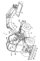
前記対地作業装置9は、旋回台6の前部側にブームシリンダ43によって上下揺動可能に設けられたブーム42を有すると共に該ブーム42の先端にアームシリンダ45によって上下揺動可能なアーム44を有し、このアーム44の先端に作業具シリンダ47によって左右軸心回りに上下揺動可能な作業具(バケット等)46を有している。
作業具46は、その左右中央部が前後軸心回りに回動自在に支持され、チルトシリンダ184によって左右両側が上下に揺動可能とされている。
A pivot shaft (swivel joint) 5 is disposed concentrically with the pivot axis 5S at the center of the inner periphery of the pivot bearing 36.
The ground work device 9 has a boom 42 provided on the front side of the swivel base 6 so as to be swingable up and down by a boom cylinder 43, and an arm 44 swingable up and down by an arm cylinder 45 at the tip of the boom 42. The arm 44 has a work tool (bucket or the like) 46 that can swing up and down around the left and right axis by a work tool cylinder 47.
The work tool 46 is supported so that its left and right central portions can rotate about the front and rear axis, and the left and right sides of the work tool 46 can be swung up and down by a tilt cylinder 184.
旋回台6上の前部には、対地作業装置9を旋回台6の上側で左右揺動自在に支持する作業装置支持部37が立設され、旋回台6の後部に後壁部34が立設され、中途部に立設された左右立ち上がりリブ35は作業装置支持部37と後壁部34とを接続しており、これらによって旋回台6を強固な立体構造物に形成している。
前記操縦装置8のハンドル73は旋回台6の前部の左右方向略中央(左側に偏位していてもよい)に配置されているのに対し、作業装置支持部37は右側に若干偏位されており、対地作業装置9の作業状態を見やすくしている。
At the front part on the swivel base 6, a work device support part 37 that supports the ground work device 9 on the upper side of the swivel base 6 so as to be able to swing left and right is erected, and a rear wall part 34 stands at the rear part of the swivel base 6. The left and right rising ribs 35 which are provided and are erected in the middle part connect the working device support part 37 and the rear wall part 34, thereby forming the swivel base 6 in a solid three-dimensional structure.
The handle 73 of the control device 8 is disposed at the substantially horizontal center (may be displaced to the left) of the front portion of the swivel 6, whereas the work device support portion 37 is slightly displaced to the right. This makes it easy to see the working state of the ground work device 9.
図1〜4、図14、図23、図24において、作業装置支持部37は、左右立上りリブ35の前端を連結しかつ操縦装置8の前側を覆うように旋回台6の前部に立設され、縦軸状のスイング軸39を支持している。
このスイング軸39にスイングシリンダ41で揺動されるスイング体40を枢支し、このスイング体40に横軸48A、48Bを介してブーム42及びこのブーム42を昇降するブームシリンダ43を枢支している。
前記スイングシリンダ41は、旋回軸5の上方で且つ左右のリブ35間に配置されている。
1 to 4, 14, 23, and 24, the work device support portion 37 is erected on the front portion of the swivel base 6 so as to connect the front ends of the left and right rising ribs 35 and cover the front side of the control device 8. The vertical swing shaft 39 is supported.
A swing body 40 that is swung by a swing cylinder 41 is pivotally supported on the swing shaft 39, and a boom 42 and a boom cylinder 43 that lifts and lowers the boom 42 are pivotally supported on the swing body 40 via horizontal axes 48A and 48B. ing.
The swing cylinder 41 is disposed above the pivot shaft 5 and between the left and right ribs 35.
前記スイング体40は作業装置支持部37の上部に枢支され、作業装置支持部37の下部には縦軸の回動軸163が枢支され、この回動軸163に上アーム164と下アーム165とが固定され、上アーム164はリンク166を介してスイング体40と連結され、下アーム165はスイングシリンダ41に連結されており、下位のスイングシリンダ41の作動力を上位のスイング体40に伝達するための立ち上がり連動手段を構成している。
前記スイング体40の下部のブーム42を枢支している部分は、旋回台6外周(旋回時の外周回転軌跡)から径外方向に突出しており、スイング体40の上部のブームシリンダ43の基部を枢支している部分は、スイング軸39の略上方で旋回台6外周以内に位置している。
The swing body 40 is pivotally supported on the upper portion of the work device support portion 37, and a rotary shaft 163 having a vertical axis is pivotally supported on the lower portion of the work device support portion 37, and an upper arm 164 and a lower arm are supported on the rotary shaft 163. 165 is fixed, the upper arm 164 is connected to the swing body 40 via the link 166, and the lower arm 165 is connected to the swing cylinder 41, and the operating force of the lower swing cylinder 41 is transferred to the upper swing body 40. It constitutes rising interlocking means for transmission.
The part pivotally supporting the lower boom 42 of the swing body 40 protrudes radially outward from the outer periphery of the swivel base 6 (the outer periphery rotation trajectory during turning), and the base of the boom cylinder 43 above the swing body 40. Is pivotally positioned above the swing shaft 39 and within the outer periphery of the swivel base 6.
前記作業装置支持部37は旋回台6の外周の略範囲内に収まるように配置されており、スイング体40の高さを、ブーム42及びブームシリンダ43が走行体4側の最高位置の上方を通過可能な高さに設定しており、ブーム42を後方へ旋回しても、ブーム42が水平姿勢よりも上方の姿勢であればボンネットカバー80の前部に当接しないようになっている。
即ち、旋回台6上の対地作業装置9は旋回しても走行体4側と衝突しない構成であり、旋回台6を後ろ向き姿勢にした状態での対地作業ができ、走行体4の全周囲での掘削作業等を可能にしている。
The work device support portion 37 is disposed so as to be within a substantially range of the outer periphery of the swivel base 6, and the height of the swing body 40 is set above the highest position on the traveling body 4 side of the boom 42 and the boom cylinder 43. The height is set so that it can pass, and even if the boom 42 is turned rearward, it does not come into contact with the front portion of the bonnet cover 80 if the boom 42 is in a position higher than the horizontal position.
That is, the ground work device 9 on the turntable 6 is configured not to collide with the traveling body 4 side even when turning, and can perform ground work in a state where the turntable 6 is in the backward posture. Excavation work is possible.
前記ブームシリンダ43、アームシリンダ45、作業具シリンダ47、チルトシリンダ184、スイングシリンダ41は油圧シリンダによって構成されている。
走行体4はエンジン13及び動力伝達機構14を有する走行駆動装置12、車体フレーム21、前輪2を縣架している前輪装置61F、後輪3を縣架している後輪装置61R等を備えている。
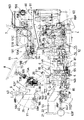
また、走行体4には、後部にエンジン13が配置され、前部には走行体4側に備えられた油圧機器を制御する切換弁169,175,178,197,198を集約してなる切換弁集合体54が配置(図4,図6,図27参照)されており、上部構造体11には、運転席7の前方に操縦装置8が配置されている。
The boom cylinder 43, the arm cylinder 45, the work tool cylinder 47, the tilt cylinder 184, and the swing cylinder 41 are constituted by hydraulic cylinders.
The traveling body 4 includes a traveling drive device 12 having an engine 13 and a power transmission mechanism 14, a vehicle body frame 21, a front wheel device 61F that mounts the front wheel 2, a rear wheel device 61R that mounts the rear wheel 3, and the like. ing.
Further, the traveling body 4 is provided with an engine 13 at the rear, and a switching valve 169, 175, 178, 197, 198 for controlling hydraulic equipment provided on the traveling body 4 side is integrated at the front. A valve assembly 54 is disposed (see FIGS. 4, 6, and 27), and a steering device 8 is disposed in front of the driver's seat 7 in the upper structure 11.
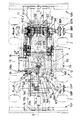
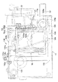
図2、4、5、8〜10において、前記車体フレーム21は平面視ラダー形状で、左右一対の角パイプ製の側部フレーム22の前後部を板形状の前後フレーム23F、23Rで連結し、中途部を旋回軸受36を装着する軸受支持部材25で連結し、その他、前後方向複数の連結部材で連結している。また、左右側部フレーム22には、中途部から後部にかけて内部にエンジン13を配置して連結し、後部に搭載したラジエータ62も連結している。
前記車体フレーム21の平面視において、左右各側部フレーム22は、旋回台6とオーバラップしている中途部22aが前後部よりも左右方向広幅に形成され、かつ前後部から前後2カ所で屈曲されて互いに外側へ台形状の膨出形状となっている。
2, 4, 5, 8 to 10, the vehicle body frame 21 has a ladder shape in plan view, and the front and rear portions of a pair of left and right side pipes 22 are connected by plate-like front and rear frames 23F and 23R. The midway part is connected by a bearing support member 25 to which the slewing bearing 36 is mounted, and is connected by a plurality of connecting members in the front-rear direction. The left and right side frames 22 are connected with the engine 13 arranged from the middle to the rear, and a radiator 62 mounted on the rear is also connected.
In the plan view of the vehicle body frame 21, the left and right side frames 22 each have a midway portion 22 a that overlaps the swivel base 6 so as to be wider in the left-right direction than the front and rear portions, and bends from the front and rear portions at two front and rear locations. As a result, it has a trapezoidal bulging shape outward.
前記車体フレーム21の側面視において、左右各側部フレーム22は、旋回台6の下方となる中途部22aが最下位に位置し、この中途部22aから前後に持ち上がって前後部は高位置に位置し、前後部の下方に前後輪2,3の縣架装置61F,61Rを配置可能にしている。
左右各側部フレーム22は、中途部22aの左右幅を前後部の左右幅より広く形成し、中途部22aと前後部との繋ぎ部分には上下面に補強板22bを設けている。
前記ラダー形状の車体フレーム21は、中途部22aが前後部から左右外側方へ拡開した形状で、左右側部が旋回軸受36の外周の外側に位置しかつ旋回軸受36の外周と旋回台6の外周との間にするようになっており、上方荷重を十分に支持すると共に前後方向の負荷に対しても負荷分散ができる強固な構造であり、中途部22aを前後部よりも低くして、旋回軸受36及び旋回台6を前後輪2,3の上端よりも低位置に配置できる構造となっている。
In the side view of the vehicle body frame 21, the left and right side frames 22 have a midway portion 22 a below the swivel base 6 positioned at the lowest position, and the front and rear portions are positioned at a high position by lifting from the midway portion 22 a back and forth. In addition, the racks 61F and 61R for the front and rear wheels 2 and 3 can be arranged below the front and rear portions.
Each of the left and right side frames 22 is formed so that the left and right width of the midway portion 22a is wider than the left and right widths of the front and rear portions, and reinforcing plates 22b are provided on the upper and lower surfaces at the connecting portion between the midway portion 22a and the front and rear portions.
The ladder-shaped body frame 21 has a shape in which a midway portion 22a is expanded from the front and rear portions to the left and right outer sides, the left and right side portions are located outside the outer periphery of the swivel bearing 36, and the outer periphery of the swivel bearing 36 and the swivel 6 It is designed to be between the outer periphery and the upper part of the structure, and it has a strong structure that can fully support the upper load and distribute the load even in the longitudinal direction. The slewing bearing 36 and the slewing base 6 can be arranged at a position lower than the upper ends of the front and rear wheels 2 and 3.
前輪縣架装置61Fは、図2、3に示すように、円筒状の前車軸ケース(デフケース)63F内に前輪デフ装置64Fを収納し、この前車軸ケース63Fの左右方向中央を、車体フレーム21の前下部に前後方向のセンタピン65Fを介して左右端部が上下揺動するように支持している。
また、前車軸ケース63Fの左右端部にキングピンを支持するベベルギヤケース66Fを設け、このベベルギヤケース66Fにキングピン回り揺動自在に終伝動ケース67Fを設け、この終伝動ケース67Fを支持された車輪軸68Fに前輪2を取り付け、操舵手段69で終伝動ケース67Fを介して左右前輪2を操舵可能にしている。
As shown in FIGS. 2 and 3, the front wheel mounting device 61F houses a front wheel differential device 64F in a cylindrical front axle case (difference case) 63F, and the vehicle body frame 21 is centered in the left-right direction of the front axle case 63F. The left and right end portions are supported so as to swing up and down via a center pin 65F in the front-rear direction.
Further, a bevel gear case 66F that supports a king pin is provided at the left and right ends of the front axle case 63F, and a final transmission case 67F is provided on the bevel gear case 66F so as to be swingable around the king pin. The wheel shaft on which the final transmission case 67F is supported The front wheel 2 is attached to 68F, and the left and right front wheels 2 can be steered by the steering means 69 via the final transmission case 67F.
図3、11において、後輪縣架装置61Rは前輪縣架装置61Fと同様に、円筒状の後車軸ケース63R内に後輪デフ装置64Rを収納し、後車軸ケース63Rの左右端部にキングピン66aを支持するベベルギヤケース66Rを設け、このベベルギヤケース66Rにキングピン66a回り揺動自在に終伝動ケース67Rを設け、この終伝動ケース67Rに支持された車輪軸68Rに後輪3を取り付け、後操舵手段69で終伝動ケース67Rを介して左右後輪3を操舵可能にしている。
前記後輪縣架装置61Rは前輪縣架装置61Fと同様に、後車軸ケース63Rの左右方向中央を、車体フレーム21の後下部の前後方向のセンタピンを介して左右端部が上下揺動するように支持してもよいが、実施形態では、後車軸ケース63Rは車体フレーム21に対して固定されている。
3 and 11, a rear wheel rack 61R, like the front wheel rack 61F, houses a rear wheel differential device 64R in a cylindrical rear axle case 63R, and a king pin at the left and right ends of the rear axle case 63R. A bevel gear case 66R for supporting 66a is provided, a final transmission case 67R is provided on the bevel gear case 66R so as to be swingable about the king pin 66a, and the rear wheel 3 is attached to the wheel shaft 68R supported by the final transmission case 67R for rear steering. By means 69, the left and right rear wheels 3 can be steered via the final transmission case 67R.
In the same manner as the front wheel rack 61F, the rear wheel rack 61R swings up and down at the center in the left-right direction of the rear axle case 63R via a center pin in the front-rear direction of the rear lower part of the body frame 21. However, in the embodiment, the rear axle case 63 </ b> R is fixed to the vehicle body frame 21.
前記後輪縣架装置61Rは、後車軸ケース63Rが左右分割体で形成されていて、一方の分割体に後輪デフ装置64Rを内蔵し、動力伝達機構14から動力が伝達されるベベルピニオン軸86Rを突入支持しており、他方の分割体は後輪デフ装置64R及びベベルピニオン軸86Rを支持しない形状となっている。
左右各後車軸ケース63Rは、外端にブレーキ部63aを形成し、このブレーキ部63aより内側にデフロック部63bを形成し、左右各ブレーキ部63aの外端にベベルギヤケース66Rを固定し、このベベルギヤケース66Rに後輪3を車輪軸68Rを介して支持した終伝動ケース67Rを取り付け、前記後輪デフ装置64Rから左右ベベルギヤケース66R内までデフヨーク軸70を貫通し、このデフヨーク軸70とブレーキ部63aとの間に油圧式のブレーキ機構Aを配置し、デフヨーク軸70とデフロック部63bとの間に油圧式のデフロック177を配置している。
In the rear wheel rack 61R, a rear axle case 63R is formed of a left and right divided body, a rear wheel differential device 64R is built in one divided body, and a bevel pinion shaft to which power is transmitted from the power transmission mechanism 14 is provided. The other divided body has a shape that does not support the rear wheel differential device 64R and the bevel pinion shaft 86R.
Each of the left and right rear axle cases 63R has a brake portion 63a formed at the outer end, a differential lock portion 63b formed inside the brake portion 63a, and a bevel gear case 66R fixed to the outer ends of the left and right brake portions 63a. A final transmission case 67R that supports the rear wheel 3 via a wheel shaft 68R is attached to the case 66R, and the differential yoke shaft 70 penetrates from the rear wheel differential device 64R into the left and right bevel gear case 66R. The differential yoke shaft 70 and the brake portion 63a. A hydraulic brake mechanism A is disposed between the differential yoke shaft 70 and the differential lock portion 63b. A hydraulic differential lock 177 is disposed between the differential yoke shaft 70 and the differential lock portion 63b.
前記ベベルギヤケース66Rはブレーキ部63aの外端に嵌入してインロウ結合されており、ブレーキ機構AのディスクA1をベベルギヤケース66Rの嵌入部66bに押圧するピストンA2がブレーキ部63a内に設けられており、外部から供給される油圧によってピストンA2を押動することにより、ディスクA1をベベルギヤケース66Rの嵌入部66bに押圧して、デフヨーク軸70を制動するようになっている。
左右各後車軸ケース63Rは、互いに対向するシリンダ取り付け部を突出していて、この両シリンダ取り付け部に操舵手段69のステアリング用シリンダ71を取り付けている。
The bevel gear case 66R is inserted into the outer end of the brake part 63a and is in-row coupled, and a piston A2 that presses the disc A1 of the brake mechanism A against the insertion part 66b of the bevel gear case 66R is provided in the brake part 63a. The piston A2 is pushed by hydraulic pressure supplied from the outside, whereby the disc A1 is pressed against the fitting portion 66b of the bevel gear case 66R to brake the differential yoke shaft 70.
Each of the left and right rear axle cases 63R protrudes from cylinder mounting portions facing each other, and a steering cylinder 71 of the steering means 69 is mounted to both the cylinder mounting portions.
操舵手段69は、後車軸ケース63Rに設けられた油圧シリンダ(パワーステアリングシリンダ)71と、この油圧シリンダ71のピストンロッド71aの両端と左右終伝動ケース67Rとを連結するタイロッド72とで構成されていて、ピストンロッド71aの左右移動で左右終伝動ケース67Rをキングピン66a回りに回動して、後輪3を操舵する。
前記左終伝動ケース67Rにはアーム120が固定されており、このアーム120には第1連動ロッド121が連結されている。122は中途部が左側部フレーム22の中途部22aに縦軸を介して枢支された連動体で、この連動体122の両端に前記第1連動ロッド121と第2連動ロッド123の一端部が連結されており、第2連動ロッド123の他端部は前輪2用左終伝動ケース67Fに設けたアーム124に連結されており、左右終伝動ケース67Fのナックルアーム125をタイロッド126で連結している。
The steering means 69 includes a hydraulic cylinder (power steering cylinder) 71 provided in the rear axle case 63R, and tie rods 72 that connect both ends of the piston rod 71a of the hydraulic cylinder 71 and the left and right end transmission cases 67R. The left and right end transmission case 67R is rotated around the king pin 66a by the left and right movement of the piston rod 71a, and the rear wheel 3 is steered.
An arm 120 is fixed to the left end transmission case 67R, and a first interlocking rod 121 is connected to the arm 120. Reference numeral 122 denotes an interlocking body having a midway part pivotally supported by a midway part 22 a of the left side frame 22 via a vertical axis. One end portions of the first interlocking rod 121 and the second interlocking rod 123 are provided at both ends of the interlocking body 122. The other end of the second interlocking rod 123 is connected to the arm 124 provided in the left end transmission case 67F for the front wheel 2, and the knuckle arm 125 of the left and right end transmission case 67F is connected by the tie rod 126. Yes.
前記操舵手段69は、油圧シリンダ71を作動して後輪3を操舵すると、連動体122及び第1、第2連動ロッド121、123を介して前輪2も同時に操舵されるようになっており、前後輪2、3の操舵方向は逆になっている。なお、前後輪2、3の操舵方向を同一にすることもできる。
前記走行体4は、走行駆動装置12から前輪デフ装置64F及び後輪デフ装置64Rへ動力が伝達される2軸4輪駆動型であり、1つのハンドル73の操舵で前後操舵手段69F、69Rを介して前後輪2、3を互いに逆方向(又は同一方向でもよい)に操舵する4輪操舵型となっている。
When the steering means 69 operates the hydraulic cylinder 71 to steer the rear wheel 3, the front wheel 2 is also steered simultaneously via the interlocking body 122 and the first and second interlocking rods 121, 123. The steering directions of the front and rear wheels 2 and 3 are reversed. The steering directions of the front and rear wheels 2 and 3 can be made the same.
The traveling body 4 is a two-shaft four-wheel drive type in which power is transmitted from the traveling drive device 12 to the front wheel differential device 64F and the rear wheel differential device 64R, and the front / rear steering means 69F and 69R are controlled by steering a single handle 73. In this manner, the front and rear wheels 2, 3 are steered in opposite directions (or in the same direction).
しかし、走行体4は、前後輪2、3のどちらか一方のみを駆動輪、操舵輪にし、他方を従動輪、直進輪に設定する構成でもよく、前後輪2、3のどちらか一方のみ常時駆動及び常時操舵する構成で、適宜他方を駆動したり操舵したりする構成にしてもよい。
前記前後輪2、3は略同径のものを使用しているが、前後どちらか一方が大径の異径であってもよい。
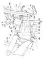
図1、2、6、7において、走行体4の前後部(前後フレーム23F、23R)にはそれぞれ、各ドーザ10F、10Rを装着するために、左右一対の上アーム支持部74U及び下アーム支持部74Dと、中央上部のシリンダ支持部75とが前方突出状に形成されている。
However, the traveling body 4 may be configured such that only one of the front and rear wheels 2 and 3 is set as a driving wheel and a steering wheel, and the other is set as a driven wheel and a straight traveling wheel. It may be configured to drive and constantly steer, and to drive or steer the other as appropriate.
The front and rear wheels 2 and 3 have substantially the same diameter, but either one of the front and rear wheels may have a large diameter.
In FIGS. 1, 2, 6, and 7, a pair of left and right upper arm support portions 74U and lower arm support are provided to attach the dozers 10F and 10R to the front and rear portions (front and rear frames 23F and 23R) of the traveling body 4, respectively. The portion 74D and the center upper cylinder support portion 75 are formed to project forward.
前後各ドーザ10F、10Rは、ブレード76と、このブレード76の背面上部に取り付けられて前記上アーム支持部74Uに横軸回り昇降自在(上下揺動自在)に枢支された左右一対の上アーム77Uと、ブレード76の背面下部に取り付けられて前記下アーム支持部74Dに横軸回り昇降自在(上下揺動自在)に枢支された左右一対の下アーム77Dと、シリンダ支持部75に枢支されていて上アーム77U及び下アーム77Dを揺動させてブレード76を昇降動作させる油圧シリンダからなるドーザシリンダ78とを有しており、ブレード76を地表に当接可能又は地中に突入可能になっている。
Each of the front and rear dozers 10F and 10R includes a blade 76 and a pair of left and right upper arms that are attached to the upper back of the blade 76 and pivotally supported by the upper arm support portion 74U so as to be movable up and down (movable up and down). 77U, a pair of left and right lower arms 77D attached to the lower back of the blade 76 and pivotally supported by the lower arm support portion 74D so as to be movable up and down (movable up and down), and pivotally supported by the cylinder support portion 75 And a dozer cylinder 78 composed of a hydraulic cylinder that moves the blade 76 up and down by swinging the upper arm 77U and the lower arm 77D, so that the blade 76 can come into contact with the ground surface or can enter the ground. It has become.
このドーザ10F、10Rは、バックホーのドーザ装置と略同一機能を有するが、対地作業装置9による掘削作業を主たる作業にすると、走行体4のスタビライザ(アウトリガ)としての機能が主体となっており、走行体4の前後片側に配置してもよいが、前後両方に配置して、作業時に走行体4を地面から持ち上げることができるようになっている。
図1、2、5〜8、14、15において、走行体4の左右側部(側部フレーム22)には、前後輪2、3間において、左右一側(左側)に燃料タンク16が取り付けられ、左右他側(右側)に作動油タンク17とその後方のバッテリー18が装備されている。燃料タンク16と作動油タンク17は左右逆になってもよく、左右分離配置することにより、走行体4の左右の重量バランスを良好にすると共に、前後輪2、3間の空間を有効利用している。
These dozers 10F and 10R have substantially the same function as the backhoe dozer device, but when the excavation work by the ground work device 9 is the main work, the main function is as a stabilizer (outrigger) of the traveling body 4, Although it may be arranged on one side of the front and rear of the traveling body 4, it is disposed on both the front and rear sides so that the traveling body 4 can be lifted from the ground during work.
1, 2, 5 to 8, 14, 15, the fuel tank 16 is attached to the left and right sides (left side) between the front and rear wheels 2 and 3 on the left and right side portions (side frame 22) of the traveling body 4. The hydraulic oil tank 17 and the battery 18 behind it are equipped on the left and right other sides (right side). The fuel tank 16 and the hydraulic oil tank 17 may be reversed right and left, and by separating them from left and right, the right and left weight balance of the traveling body 4 is improved and the space between the front and rear wheels 2 and 3 is effectively used. ing.
燃料タンク16と作動油タンク17及びバッテリー18とは、車体フレーム21に左右振り分け配置されている。作動油タンク17は右側部フレーム22に着脱自在に装着されており、正面視略L字形状で、右側部フレーム22の下側に入る延長部17aを有し、この延長部17a内にオイルフィルタ130が配置され、また、平面視略L字形状で、バッテリー18を配置する凹部17bを形成している。
前記凹部17bは作動油タンク17の後部側で左右内側部分に形成され、ここにバッテリー18を配置することで、該バッテリー18が作動油タンク17により外側方及び前方からカバーされるようになっている。
The fuel tank 16, the hydraulic oil tank 17, and the battery 18 are arranged on the vehicle body frame 21 in a left-right manner. The hydraulic oil tank 17 is detachably attached to the right side frame 22, has a substantially L-shape in front view, and has an extension part 17a that enters the lower side of the right side frame 22, and an oil filter is provided in the extension part 17a. 130 is disposed, and has a substantially L shape in plan view, and forms a recess 17b in which the battery 18 is disposed.
The concave portion 17b is formed in the left and right inner portions on the rear side of the hydraulic oil tank 17, and by arranging the battery 18 here, the battery 18 is covered by the hydraulic oil tank 17 from the outside and the front. Yes.
前記作動油タンク17の前下部には大小孔128a、128bを連続した瓢箪形状の開口部128が形成され、この開口部128を閉鎖する蓋体129も瓢箪形状になっており、この蓋体129の小孔対応部129aに前記オイルフィルタ(サクションフィルタ)130とそれに連通する吸入パイプ131が接続されており、この吸入パイプ131は側部フレーム22の下側を通って各種バルブに接続されている。
前記オイルフィルタ130は蓋体129に取り付けた状態で、大孔128bから挿入して小孔128a側へ移動することにより、蓋体129が瓢箪孔に対応して取り付けるようになっており、オイルフィルタ130の開口部128への挿入容易化によってメンテナンスが容易にできるようにしている。
In the front lower part of the hydraulic oil tank 17, a bowl-shaped opening 128 having continuous large and small holes 128 a and 128 b is formed, and a lid 129 for closing the opening 128 is also bowl-shaped. The oil filter (suction filter) 130 and a suction pipe 131 communicating with the oil filter (suction filter) 130 are connected to the small hole corresponding portion 129a. The suction pipe 131 is connected to various valves through the lower side of the side frame 22. .
When the oil filter 130 is attached to the lid body 129, it is inserted through the large hole 128b and moved toward the small hole 128a, so that the lid body 129 is attached corresponding to the fistula. Maintenance is facilitated by facilitating insertion of the 130 into the opening 128.
132は吐出パイプであり、作動油タンク17のポンプ133からバッテリー18及び側部フレーム22の下側を通ってエンジン13側の油圧ポンプに接続されている。
右側部フレーム22の上部には複数本の掛止ピン134aが突設され、作動油タンク17をこの掛止ピン134aに仮止めできるようになっており、前記掛止ピン134a及びそれに掛止される作動油タンク17側の孔付きの掛止部材134bとによってタンク仮止め手段134が構成されている。
また、仮止め手段134により仮止めした作動油タンク17は本装着手段136により本止めされるようになっており、この本装着手段136は、作動油タンク17上面に固定した正面L字型の被掛止具135cに掛止される前後方向のロッド135dと、このロッド135dの両端にナット135eにより締結される掛止具135aと、を有し、この掛止具135aの下端部を、右側部フレーム22に取り付けた孔付きの掛止部材139aやブラケット139bに引っ掛けてナット135eを締め付け、作動油タンク17を右側部フレーム22側へ引きつけることによって本止めするようになっている。
A discharge pipe 132 is connected from the pump 133 of the hydraulic oil tank 17 to the hydraulic pump on the engine 13 side through the battery 18 and the lower side of the side frame 22.
A plurality of latching pins 134a project from the upper portion of the right side frame 22 so that the hydraulic oil tank 17 can be temporarily secured to the latching pins 134a. The tank temporary fixing means 134 is constituted by a hooking member 134b with a hole on the hydraulic oil tank 17 side.
Further, the hydraulic oil tank 17 temporarily fixed by the temporary fixing means 134 is finally fixed by the main mounting means 136. The main mounting means 136 is a front L-shaped fixed to the upper surface of the hydraulic oil tank 17. A rod 135d in the front-rear direction that is hooked on the hook 135c and a hook 135a that is fastened by nuts 135e to both ends of the rod 135d. The lower end of the hook 135a is connected to the right side. The nut 135e is tightened by being hooked on a hooking member 139a with a hole attached to the part frame 22 or the bracket 139b, and the hydraulic oil tank 17 is pulled to the right side frame 22 side to make a full stop.
本装着手段136は、作動油タンク17を右側部フレーム22に対してボルト等の締結具により固定するものであってもよい。
右側部フレーム22の下面と延長部17aとの間にはゴム等のクッション材137が配置され、作動油タンク17の上面が略水平になるように、作動油タンク17を支持している。
この作動油タンク17は、図8に2点鎖線で示すように、外側面と上面とが正面視略逆L字状のカバー138で覆われており、このカバー138は金属板又はプラスチックで形成され、作動油タンク17の前後両側で右側部フレーム22に固定されたブラケット139bに台座等を介して取り付けられている。カバー138の上水平部はステップ部138Aとなっている。
The mounting means 136 may fix the hydraulic oil tank 17 to the right side frame 22 with a fastener such as a bolt.
A cushion material 137 such as rubber is disposed between the lower surface of the right side frame 22 and the extension portion 17a, and supports the hydraulic oil tank 17 so that the upper surface of the hydraulic oil tank 17 is substantially horizontal.
As shown by a two-dot chain line in FIG. 8, the hydraulic oil tank 17 is covered with a cover 138 whose outer surface and upper surface are substantially L-shaped when viewed from the front. The cover 138 is formed of a metal plate or plastic. The bracket 139b is fixed to the right frame 22 on both the front and rear sides of the hydraulic oil tank 17 via a pedestal or the like. An upper horizontal portion of the cover 138 is a step portion 138A.
燃料タンク16はプラスチック又は板金で形成され、左側部フレーム22の外側面に固定されている。
具体的に左側部フレーム22の外側面には前後一対のブラケット190が左右外方に突設され、この前後ブラケット190に対してその前後間に燃料タンク16が取り付けられている。
この燃料タンク16は、作動油タンク17と同様に、側部フレーム22の下側に入る延長部を有する略L字形状に形成して、タンク仮止め手段及びタンク本装着手段を介して取り付けてもよい。
The fuel tank 16 is made of plastic or sheet metal and is fixed to the outer surface of the left side frame 22.
Specifically, a pair of front and rear brackets 190 project from the left and right outwards on the outer surface of the left side frame 22, and the fuel tank 16 is attached to the front and rear brackets 190 between the front and rear.
Like the hydraulic oil tank 17, the fuel tank 16 is formed in a substantially L shape having an extension that enters the lower side of the side frame 22, and is attached via a tank temporary fixing means and a tank main mounting means. Also good.
また、作動油タンク17と同様に、燃料タンク16の上面及び外側面もカバー191により覆われており、このカバー191は、ブラケット190に台座190aを介して取り付けられている。このカバー191の上水平部はステップ部191Aとされている。
なお、前記カバー138、191はタンク17、16の上面のみを覆う平板であってもよく、タンク17、16に固定されていてもよい。
図1〜4、6、7、12、13において、前記走行体4は、旋回台6の下方部分が扁平形状部4Aでかつ旋回台6の後方部分が嵩高形状部4Bになっており、嵩高形状部4Bにはボンネットカバー80が着脱自在又は開閉自在に設けられている。
Similarly to the hydraulic oil tank 17, the upper surface and the outer surface of the fuel tank 16 are also covered with a cover 191, and this cover 191 is attached to the bracket 190 via a base 190a. The upper horizontal portion of the cover 191 is a step portion 191A.
The covers 138 and 191 may be flat plates that cover only the upper surfaces of the tanks 17 and 16, and may be fixed to the tanks 17 and 16.
1-4, 6, 7, 12, and 13, the traveling body 4 has a lower part of the swivel base 6 as a flat part 4A and a rear part of the swivel base 6 as a bulky part 4B. A bonnet cover 80 is detachably or closably provided on the shape portion 4B.
走行体4の前記嵩高形状部4Bのボンネットカバー80内にはエンジン13が配置され、前記扁平形状部4Aには動力伝達機構14が配置されている。この動力伝達機構14を内蔵した扁平形状部4Aの上方に旋回台6が配置され、エンジン13は旋回台6の下方から後方へ飛び出した配置構造になっている。
前記エンジン13はクランク軸13Aの軸心を左右方向に配置してもよいが、ここでは前後方向に沿う配置であり、左右方向の中心13S(図3参照)は車体フレーム21の左右方向中心(旋回軸5の中心線(旋回中心)5Sを通る)と同心又は左右一方(左側)に僅かにずれて配置されている。
An engine 13 is disposed in the hood cover 80 of the bulky shape portion 4B of the traveling body 4, and a power transmission mechanism 14 is disposed in the flat shape portion 4A. The swivel base 6 is disposed above the flat portion 4A incorporating the power transmission mechanism 14, and the engine 13 has a structure in which the engine 13 protrudes rearward from the bottom of the swivel base 6.
The engine 13 may be arranged with the axis of the crankshaft 13A in the left-right direction, but here it is arranged along the front-rear direction, and the center 13S in the left-right direction (see FIG. 3) is the center in the left-right direction of the body frame 21 ( It is arranged concentrically with the center line (turning center) 5S of the turning shaft 5 or slightly shifted to the left or right (left side).
エンジン13の後方側に配置されたラジエータ62は、車体フレーム21の左右方向中心に配置してもよいが、エンジン13と同じ側に偏位して配置されている。
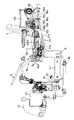
前記扁平形状部4Aの動力伝達機構14は機械式トランスミッションでもよいが、ここではポンプ81及びモータ82を有する静油圧式のトランスミッション(HST)26と減速装置87とを組み合わせており、図3,図4、図12,図13に示すように、この静油圧式トランスミッション26のミッションケース83に、エンジン13から動力が伝達されるポンプ81側の入力軸27とモータ82側の出力軸28とを支持し、これらをそれぞれ平面視において略前後方向に沿わせている。トランスミッション26のミッションケース83と減速装置87の前後ケース87A、87Bとは一体的に結合されており、前記入力軸27と出力軸28とは、側面視において、若干前下がりに傾斜配置されている。
The radiator 62 disposed on the rear side of the engine 13 may be disposed at the center in the left-right direction of the vehicle body frame 21, but is deviated on the same side as the engine 13.
The power transmission mechanism 14 of the flat shape portion 4A may be a mechanical transmission, but here, a hydrostatic transmission (HST) 26 having a pump 81 and a motor 82 is combined with a reduction gear 87, and FIG. 4, 12 and 13, the transmission case 83 of the hydrostatic transmission 26 supports a pump 81 side input shaft 27 and a motor 82 side output shaft 28 to which power is transmitted from the engine 13. However, these are arranged along the front-rear direction in plan view. The transmission case 83 of the transmission 26 and the front and rear cases 87A and 87B of the speed reducer 87 are integrally coupled, and the input shaft 27 and the output shaft 28 are inclined slightly forward and downward in a side view. .
減速装置87は前後ケース87A、87B内に2組の減速ギヤ群107、108を収納しており、前後ケース87A、87Bは上下幅が短く左右幅が長く形成されており、前ケース87Aにはチャージポンプ109とこのチャージポンプ109によって制御される油圧クラッチ110とが設けられている。
前記入力軸27はミッションケース83から前後に突出していて、後方側はフライホィールを介してクランク軸13Aと連結され、前方側は減速装置87の後ケース87Bに支持され、減速ギヤ群107のギヤ107Aが装着されていると共に、チャージポンプ109を駆動可能になっている。
The reduction gear 87 houses two sets of reduction gear groups 107 and 108 in the front and rear cases 87A and 87B. The front and rear cases 87A and 87B are formed with a short vertical width and a long horizontal width. A charge pump 109 and a hydraulic clutch 110 controlled by the charge pump 109 are provided.
The input shaft 27 protrudes forward and backward from the mission case 83, the rear side is connected to the crankshaft 13 </ b> A via a flywheel, and the front side is supported by the rear case 87 </ b> B of the speed reducer 87. 107A is mounted and the charge pump 109 can be driven.
減速ギヤ群107のギヤ107Aはギヤ107Bと噛合しており、このギヤ107Bは油圧クラッチ110のクラッチ入力軸111に装着されている。油圧クラッチ110のクラッチ入力軸111とクラッチ出力軸112との間にクラッチ手段113が設けられており、チャージポンプ109から圧油で断接可能になっている。
クラッチ出力軸112は自在継手軸を介して、負荷の大きな作動油供給用の油圧ポンプ85を駆動するようになっている。
前記チャージポンプ109はトロコイドポンプ等で形成され、エンジン13が駆動しているときは駆動され、クラッチ手段113に所要圧の圧油を供給して接状態に維持し、エンジン13が停止するとチャージポンプ109も停止して、クラッチ手段113をオフにする。従って、エンジン13を始動するとき、クラッチ出力軸112に油圧ポンプ85の負荷を加えない状態で行うことができ、起動時の負荷を軽減できる。
The gear 107 </ b> A of the reduction gear group 107 meshes with the gear 107 </ b> B, and this gear 107 </ b> B is attached to the clutch input shaft 111 of the hydraulic clutch 110. A clutch means 113 is provided between the clutch input shaft 111 and the clutch output shaft 112 of the hydraulic clutch 110, and can be connected and disconnected from the charge pump 109 with pressure oil.
The clutch output shaft 112 drives a hydraulic pump 85 for supplying hydraulic oil with a large load via a universal joint shaft.
The charge pump 109 is formed by a trochoid pump or the like, and is driven when the engine 13 is driven. The charge pump 109 is supplied with pressure oil of a required pressure to maintain the contact state, and when the engine 13 is stopped, the charge pump is driven. 109 also stops and the clutch means 113 is turned off. Therefore, when the engine 13 is started, it can be performed without applying the load of the hydraulic pump 85 to the clutch output shaft 112, and the load at the time of starting can be reduced.
前記モータ82の出力軸28には減速ギヤ群108のギヤ108Aが設けられ、このギヤ108Aは推進軸114に設けたギヤ108Bと噛合している。前記推進軸114は、減速装置87は前後ケース87A、87Bから前後に突出していて、前後自在継手軸29F、29Rを介して前輪デフ装置64F及び後輪デフ装置64Rの各ベベルピニオン軸86F、86Rと連結されている。
前後輪2、3への動力伝達に前後自在継手軸29F、29Rを使用することにより、ベベルピニオン軸86F、86Rがセンタピン65から左右方向にずれた位置にあっても、推進軸114が前下向き傾斜していても、前後輪デフ装置64への動力伝達を可能にし、かつ前車軸ケース63Fの上下揺動を可能にしている。
The output shaft 28 of the motor 82 is provided with a gear 108 </ b> A of the reduction gear group 108, and this gear 108 </ b> A is engaged with a gear 108 </ b> B provided on the propulsion shaft 114. In the propulsion shaft 114, the speed reducer 87 projects forward and backward from the front and rear cases 87A and 87B, and the bevel pinion shafts 86F and 86R of the front wheel differential device 64F and the rear wheel differential device 64R via the front and rear universal joint shafts 29F and 29R. It is connected with.
By using the front and rear universal joint shafts 29F and 29R for power transmission to the front and rear wheels 2 and 3, even when the bevel pinion shafts 86F and 86R are displaced from the center pin 65 in the left-right direction, the propulsion shaft 114 is directed forward and downward. Even if the vehicle is inclined, power can be transmitted to the front and rear wheel differential device 64, and the front axle case 63F can be swung up and down.
図1〜7において、走行体4上には旋回台6を旋回自在に支持する旋回軸受36と、旋回軸受36の内周に設けたリングギヤ88と、このリングギヤ88と噛合している駆動ピニオン89と、この駆動ピニオン89を駆動して旋回台6を旋回させる油圧式旋回モータ15と、旋回軸5とが設けられている。
旋回軸受36の中心5S(内周側中心部)に配置された旋回軸5はスイベルジョイントで構成され、油圧ポンプ85と旋回台6側の油圧制御弁等とを接続する作動油回路、油圧ポンプ85等と旋回台6側のパイロット切換弁を操作するリモコン弁とを接続するパイロット回路、旋回台6側の油圧制御弁と走行体4側の油圧機器とを接続する作動油回路、旋回台6側の操作手段と走行体側の電気機器(スタータ、電磁弁等)とを接続する電気回路等を、旋回台6が回転しているときでも接続可能にしている。
1 to 7, a swing bearing 36 that rotatably supports the swivel base 6 on the traveling body 4, a ring gear 88 provided on the inner periphery of the swing bearing 36, and a drive pinion 89 that meshes with the ring gear 88. In addition, a hydraulic turning motor 15 that drives the drive pinion 89 to turn the turntable 6 and a turning shaft 5 are provided.
The swivel shaft 5 disposed at the center 5S (inner peripheral side center) of the swivel bearing 36 is composed of a swivel joint, and a hydraulic oil circuit that connects the hydraulic pump 85 and a hydraulic control valve on the swivel base 6 side, a hydraulic pump 85, etc. and a pilot circuit for connecting a remote control valve for operating a pilot switching valve on the swivel base 6, a hydraulic oil circuit for connecting a hydraulic control valve on the swivel base 6 and a hydraulic device on the traveling body 4, a swivel base 6 An electric circuit or the like that connects the operation means on the side and the electrical equipment (starter, solenoid valve, etc.) on the traveling body side can be connected even when the swivel base 6 is rotating.
前記旋回モータ15、自在継手軸29、油圧ポンプ85等は走行駆動装置12の動力伝達機構14の一部を構成するものであり、車体フレーム21の上面より低くかつエンジン13の下端よりも高い範囲に略納められ、旋回軸5の周囲で、上下方向においても、前後方向及び左右方向においてもコンパクトに配置されている。
前記旋回台6と、旋回軸5の旋回台6の後上部に配置された運転席7と、この運転席7の前方の旋回台6前部に配置された操縦装置8と、運転席7の周囲に配置された対地作業装置9等を操作する操作装置55等によって上部構造体11が構成されている。
The swing motor 15, the universal joint shaft 29, the hydraulic pump 85, etc. constitute a part of the power transmission mechanism 14 of the travel drive device 12, and are lower than the upper surface of the body frame 21 and higher than the lower end of the engine 13. And is arranged compactly in the vertical direction, in the front-rear direction, and in the left-right direction around the pivot shaft 5.
The swivel base 6, a driver seat 7 disposed at the rear upper part of the swivel base 6 of the swivel shaft 5, a control device 8 disposed in front of the swivel base 6 in front of the driver seat 7, The upper structure 11 is configured by an operation device 55 or the like for operating the ground work device 9 or the like disposed around.
前記旋回軸5の中心5Sは、前後輪2、3の軸間中心Pより若干前側に配置し、この旋回軸5を境にして、旋回台6の後側に運転席7を、前側に操縦装置8及び対地作業装置9をそれぞれ配置しており、上部構造体11は前端が操縦装置8であり、後部が運転席7である。
図4、図23〜26に示すように、前記旋回台6の後部には、該旋回台6の後壁部34の上部から後方へ延びるように設けられていてエンジン13の上方へ張り出し状とされた運転席配置枠体51が設けられている。
The center 5S of the turning shaft 5 is arranged slightly in front of the center P between the front and rear wheels 2 and 3, and the driver's seat 7 is steered to the rear side of the turntable 6 with the turning shaft 5 as a boundary. The device 8 and the ground work device 9 are respectively arranged, and the upper structure 11 has a front end of the control device 8 and a rear portion of the driver's seat 7.
As shown in FIGS. 4 and 23 to 26, the rear part of the swivel base 6 is provided so as to extend rearward from the upper part of the rear wall part 34 of the swivel base 6, and protrudes upward from the engine 13. A driver's seat arrangement frame 51 is provided.
この運転席配置枠体51は、後壁部34の上面に固定の取付け板51Aに左右一対のパイプ製の横材51Bを固定し、左右横材51Bから後方へパイプ製の縦材51Cを突出し、左右縦材51Cを複数本の連結材51Dで連結して構成されている。
この運転席配置枠体51の前部には運転席7が装着され、後部(運転席7の後側)には、この旋回作業機1に装備された油圧機器(油圧アクチュエータ等)を制御する油圧制御弁56a〜gを集約してなるコントロールバルブ56、発電機159、該発電機159を駆動するための油圧モータ158、発電機159によって発生した電気を蓄えるバッテリー160が装着されている。
In this driver seat frame 51, a pair of left and right pipe cross members 51B are fixed to a mounting plate 51A fixed to the upper surface of the rear wall 34, and a pipe vertical member 51C protrudes rearward from the left and right cross members 51B. The left and right vertical members 51C are connected by a plurality of connecting members 51D.
A driver's seat 7 is attached to the front portion of the driver's seat arrangement frame 51, and a hydraulic device (such as a hydraulic actuator) installed in the turning work machine 1 is controlled at a rear portion (rear side of the driver's seat 7). A control valve 56 formed by integrating the hydraulic control valves 56a to 56g, a generator 159, a hydraulic motor 158 for driving the generator 159, and a battery 160 for storing electricity generated by the generator 159 are mounted.
前記バッテリー160が旋回作業機1の上部構造体11側の電気供給源となる。
前記コントロールバルブ56、発電機159、油圧モータ158、バッテリー160は、運転席配置枠体51に支持部材を介して取付固定されており、コントロールバルブ56は、運転席配置枠体51の左右方向略中央部に配置され、発電機159は運転席配置枠体51の左右方向一側(左側)に配置され、油圧モータ158は発電機159の前方側に配置され、バッテリー160は運転席配置枠体51の左右方向他側(右側)に配置されている。
The battery 160 serves as an electricity supply source on the upper structure 11 side of the turning work machine 1.
The control valve 56, the generator 159, the hydraulic motor 158, and the battery 160 are fixedly attached to the driver seat arrangement frame 51 via a support member, and the control valve 56 is substantially in the left-right direction of the driver seat arrangement frame 51. Arranged in the center, the generator 159 is arranged on one side (left side) of the driver seat arrangement frame 51, the hydraulic motor 158 is arranged on the front side of the generator 159, and the battery 160 is arranged in the driver seat arrangement frame. 51 is arranged on the other side (right side) in the left-right direction.
また、コントロールバルブ56は、運転席配置枠体51の左右の縦材51C間に配置されていて、コントロールバルブ56は、その重心位置が低くなるように配置されている。
また、発電機159、油圧モータ158、バッテリー160はコントロールバルブ56よりも上方側に配置されている。
エンジンが旋回台側の運転席後方に備えられた旋回作業機にあっては、該エンジンが前部の対地作業機との重量バランスを図るカウンタウエイトとして機能するが、本実施の形態の旋回作業機1にあっては、エンジン13が走行体4側に備えられているので、旋回台6の後部側に、大きなカウンタウエイトが必要とされるが、運転席7の後側(旋回台6の後部側)にコントロールバルブ56を設けることにより、該コントロールバルブ56がカウンタウエイトとしての役目を果たし、カウンタウエイトの軽量化を図ることができる(又はカウンタウエイトを不要とすることも可能である)。
The control valve 56 is arranged between the left and right vertical members 51C of the driver seat arrangement frame 51, and the control valve 56 is arranged so that the center of gravity is lowered.
Further, the generator 159, the hydraulic motor 158, and the battery 160 are disposed above the control valve 56.
In the turning work machine provided with the engine behind the driver's seat on the turntable side, the engine functions as a counterweight that balances the weight with the ground work machine in the front, but the turning work of the present embodiment In the machine 1, since the engine 13 is provided on the traveling body 4 side, a large counterweight is required on the rear side of the swivel base 6. By providing the control valve 56 on the rear side, the control valve 56 serves as a counterweight, and the weight of the counterweight can be reduced (or the counterweight can be made unnecessary).
また、本実施の形態では、さらに、発電機159、油圧モータ158、バッテリー160も運転席7の後側に設けられており、これらもカウンタウエイトとしての役目を果たし、これらによっても、カウンタウエイトの軽量化を図ることができる(又はカウンタウエイトを不要とすることも可能である)。
前記コントロールバルブ56は、直動スプール形切換弁で構成された油圧制御弁56a〜gをスプールと直交する方向で且つ前後方向に並べて配置すると共に全油圧制御弁56a〜gを連結一体化して構成されている。
Further, in the present embodiment, a generator 159, a hydraulic motor 158, and a battery 160 are also provided on the rear side of the driver's seat 7, and these also serve as counterweights. The weight can be reduced (or the counterweight can be eliminated).
The control valve 56 is configured by arranging hydraulic control valves 56a to 56g constituted by direct acting spool type switching valves side by side in a direction orthogonal to the spool and in the front and rear direction, and connecting and integrating all the hydraulic control valves 56a to 56g. Has been.
油圧制御弁56a〜gを、後端側から順に説明すると、56aはチルトシリンダ184を制御する油圧制御弁であり、56bはスイングシリンダ41を制御する油圧制御弁であり、56cは作業具シリンダ47を制御する油圧制御弁であり、56dはブームシリンダ43を制御する油圧制御弁であり、56eはアームシリンダ45を制御する油圧制御弁であり、56fは旋回モータ15を制御する油圧制御弁であり、56gはドーザシリンダ78を制御する油圧制御弁である。
また、コントロールバルブ56の各油圧制御弁56a〜gはパイロット圧によって操作されるパイロット操作切換弁によって構成されており、運転席7前部の左右両側に設けられた操作レバー55L,55R,181,182,183によって操作されるリモコン弁196L,196R,193,194,195(図21参照)からのパイロット圧によって操作される。
The hydraulic control valves 56 a to 56 g will be described in order from the rear end side. 56 a is a hydraulic control valve that controls the tilt cylinder 184, 56 b is a hydraulic control valve that controls the swing cylinder 41, and 56 c is a work implement cylinder 47. , 56d is a hydraulic control valve for controlling the boom cylinder 43, 56e is a hydraulic control valve for controlling the arm cylinder 45, and 56f is a hydraulic control valve for controlling the swing motor 15. , 56 g are hydraulic control valves for controlling the dozer cylinder 78.
Further, each of the hydraulic control valves 56a to 56g of the control valve 56 is constituted by a pilot operation switching valve operated by a pilot pressure, and operation levers 55L, 55R, 181 provided on the left and right sides of the front part of the driver's seat 7 are provided. It is operated by pilot pressure from remote control valves 196L, 196R, 193, 194, 195 (see FIG. 21) operated by 182 and 183.
なお、各油圧制御弁56a〜gは、左右方向両側にリモコン弁193,194,195196L,196Rに接続されるパイロット回路を接続する接続部が設けられ、上面側に、油圧ポンプ85及び油圧アクチュエータ15,41,43,45,47,78,184に接続される作動油回路を接続する接続部が設けられている。
また、各油圧制御弁56a〜gの上面側の接続部に接続される、油圧ホース又は鋼管等の油圧管路は、運転席7の下方又は側方を通って、各油圧アクチュエータ41,43,45,47,184、スイベルジョイント5に配管される。
Each of the hydraulic control valves 56a to 56g is provided with a connecting portion for connecting a pilot circuit connected to the remote control valves 193, 194, 195196L, 196R on both sides in the left-right direction, and the hydraulic pump 85 and the hydraulic actuator 15 on the upper surface side. , 41, 43, 45, 47, 78, 184 are connected to connect hydraulic fluid circuits.
In addition, hydraulic lines such as hydraulic hoses or steel pipes connected to the connection portions on the upper surface side of the hydraulic control valves 56a to 56g pass below or side of the driver's seat 7 and are connected to the hydraulic actuators 41, 43, 45, 47, 184 and the swivel joint 5 are piped.
また、例えば、操作レバー55Lは、対地作業装置9のアームシリンダ45及び旋回モータ15を操作するものであり、操作レバー55Rは対地作業装置9のブームシリンダ43及び作業具シリンダ47を操作するものであり、操作レバー181はスイングシリンダ41を操作するものであり、操作レバー182はチルトシリンダ184を操作するものであり、操作レバー183はドーザシリンダ78を操作するものである(これに限定されることはない)。
また、アーム44及び旋回台6操作用の操作レバー55Lは運転席7前部の左側に配置され、該操作レバー55Lによって操作されるリモコン弁196Lは該操作レバー55Lの下側に配置され、ブーム42及び作業具46操作用の操作レバー55Rは運転席7前部の右側に配置され、該操作レバー55Rによって操作されるリモコン弁196Rは該操作レバー55Rの下側に配置されている。
Further, for example, the operation lever 55L is for operating the arm cylinder 45 and the turning motor 15 of the ground work apparatus 9, and the operation lever 55R is for operating the boom cylinder 43 and work implement cylinder 47 of the ground work apparatus 9. Yes, the operation lever 181 operates the swing cylinder 41, the operation lever 182 operates the tilt cylinder 184, and the operation lever 183 operates the dozer cylinder 78 (limited to this). Not)
Further, the operation lever 55L for operating the arm 44 and the swivel base 6 is disposed on the left side of the front portion of the driver's seat 7, and the remote control valve 196L operated by the operation lever 55L is disposed below the operation lever 55L. An operation lever 55R for operating 42 and the work tool 46 is disposed on the right side of the front portion of the driver's seat 7, and a remote control valve 196R operated by the operation lever 55R is disposed below the operation lever 55R.
また、スイング体40操作用の操作レバー181は運転席7前部の左側に配置され、該操作レバー181によって操作されるリモコン弁193はコントロールバルブ56の前部左側で且つ油圧モータ158の下側に配置され、作業具46チルト用の操作レバー182は運転席7前部の右側に配置され、該操作レバー182によって操作されるリモコン弁194はコントロールバルブ56の後部右側で且つバッテリー160の下側に配置され、前後ドーザ10操作用の操作レバー183は運転席7前部の右側で且つ操作レバー182の前方側に配置され、該操作レバー183によって操作されるリモコン弁195はコントロールバルブ56の前部右側で且つバッテリー160の下側に配置されており、これら各操作レバー181,182,183とリモコン弁193,194,195とはリンク(ロッド)200A,200B,200Cを介して連動連結されている。
The operating lever 181 for operating the swing body 40 is disposed on the left side of the front portion of the driver's seat 7, and the remote control valve 193 operated by the operating lever 181 is on the left side of the front portion of the control valve 56 and below the hydraulic motor 158. The operation lever 182 for tilting the work tool 46 is disposed on the right side of the front portion of the driver's seat 7, and the remote control valve 194 operated by the operation lever 182 is on the right side of the rear portion of the control valve 56 and below the battery 160. An operation lever 183 for operating the front and rear dozers 10 is disposed on the right side of the front portion of the driver's seat 7 and on the front side of the operation lever 182, and the remote control valve 195 operated by the operation lever 183 is disposed in front of the control valve 56. The operation levers 181, 182, 18 are arranged on the right side of the unit and below the battery 160. And the remote control valve 193,194,195 are interlocked through the link (rod) 200A, 200B, and 200C.
すなわち、各操作レバー181,182,183は、運転席配置枠体51に設けられた左右方向の枢軸201A,201B,201Cに軸心回りに回動自在に外嵌された筒体202A,202B,202Cに固定されていて前後方向揺動操作自在とされ、各筒体202A,202B,202Cには径方向に突出するアーム部材203A,203B,203Cが固定され、このアーム部材203A,203B,203Cとリモコン弁193,194,195の操作部193a,194b,195cとが前記リンク200A,200B,200Cによって連動連結されていて、操作レバー181,182,183を前後に揺動されることにより、リンク200A,200B,200Cが押し引きされて、リモコン弁193,194,195の操作部193a,194b,195cが操作されるようになっている。
That is, the operation levers 181, 182, and 183 are cylindrical bodies 202 </ b> A, 202 </ b> B that are externally fitted around pivots 201 </ b> A, 201 </ b> B, 201 </ b> C in the left-right direction provided in the driver seat frame 51 so as to be rotatable about the axis. The arm members 203A, 203B, and 203C projecting in the radial direction are fixed to the cylinders 202A, 202B, and 202C. The arm members 203A, 203B, and 203C The operation portions 193a, 194b, and 195c of the remote control valves 193, 194, and 195 are interlocked and connected by the links 200A, 200B, and 200C, and the operation levers 181, 182, and 183 are swung back and forth to link 200A. , 200B, 200C are pushed and pulled to operate the remote control valves 193, 194, 195 193a, so that the 194b, 195c is operated.
なお、操作レバー181,182,183と油圧制御弁56b,56a,56gのスプールとをリンクを介して連動連結して操作レバー181,182,183によって油圧制御弁56b,56a,56gのスプールを直接操作するようにしてもよいし、操作レバー181,182,183とリモコン弁193,194,195の操作部193a,194a,195aとを直結するようにしてもよい。
また、エンジン13の調速機を操作するためのハンドアクセルレバー187や走行ロック弁175を操作するための走行ロックレバー188等も配置されており、走行ロックレバー188は運転席7の左右両側に設けられている。
The operating levers 181, 182, 183 and the spools of the hydraulic control valves 56 b, 56 a, 56 g are interlocked and connected via a link, and the spools of the hydraulic control valves 56 b, 56 a, 56 g are directly connected by the operating levers 181, 182, 183. The operation levers 181, 182 and 183 may be directly connected to the operation portions 193 a, 194 a and 195 a of the remote control valves 193, 194 and 195.
A hand accelerator lever 187 for operating the governor of the engine 13 and a travel lock lever 188 for operating the travel lock valve 175 are also arranged. The travel lock lever 188 is provided on both the left and right sides of the driver seat 7. Is provided.
操作レバーと油圧制御弁のスプールとをワイヤ、リンク(ロッド)等を介して連動連結すると、操作レバーから油圧制御弁までの経路の遊び、ガタ、たわみ等により、応答性が悪くなり、操作レバーの動きに敏感な旋回作業機を実現するのが困難であるが、前記構成の実施の形態のものにあっては、運転席7側方の操作レバー181,182,183と、コントロールバルブ56側方のリモコン弁193,194,195とを1本のリンク200A,200B,200Cによってつなげることにより、感度のよい作業機1のコントロールが期待できる。
If the operating lever and the spool of the hydraulic control valve are linked and connected via a wire, link (rod), etc., the response from the operating lever to the hydraulic control valve will become less responsive due to play, backlash, deflection, etc. Although it is difficult to realize a turning work machine that is sensitive to the movement of the driver, in the embodiment having the above-described configuration, the operation levers 181, 182, and 183 on the side of the driver's seat 7 and the control valve 56 side By connecting the remote control valves 193, 194, 195 with one link 200A, 200B, 200C, it is possible to control the work machine 1 with high sensitivity.
前記上部構造体11は旋回軸受36及び旋回台6が、走行体4後部のエンジン13上端より下位に配置されており、旋回軸受36及び旋回台6の内の少なくとも旋回軸受36が、前後輪2、3間でかつ前後輪2、3の少なくとも一方の上端よりも低い位置に配置されている。
旋回台6は平面視において、前部が平坦で後部及び左右側部が略円形状であり、後部がエンジン13に近接され、前向き姿勢で前部が左右前輪2の後端と略同一位置にあり、回転すると、その外周は左右前輪2の後端と前後方向にオーバラップする。旋回台6は車体フレーム21から左右外側方へ突出していて、燃料タンク16及び作動油タンク17と左右方向でオーバラップしている。
The upper structure 11 has a swivel bearing 36 and a swivel base 6 disposed below the upper end of the engine 13 at the rear of the traveling body 4, and at least the swivel bearing 36 of the swivel bearing 36 and the swivel base 6 has the front and rear wheels 2. 3 and at a position lower than the upper end of at least one of the front and rear wheels 2 and 3.
In plan view, the swivel base 6 has a flat front portion, a rear portion and left and right side portions that are substantially circular, a rear portion that is close to the engine 13, and a front portion that is in a forward orientation and substantially at the same position as the rear ends of the left and right front wheels 2. Yes, when rotated, the outer periphery overlaps the rear ends of the left and right front wheels 2 in the front-rear direction. The swivel base 6 protrudes from the body frame 21 to the left and right outer sides, and overlaps the fuel tank 16 and the hydraulic oil tank 17 in the left-right direction.
即ち、旋回台6は、左右方向略中央のエンジン13と左右に離れた一対の前輪2との3点内で可及的に大面積になるように設定されており、又は、旋回台6を必要面積にした上で、走行体4の前後方向及び左右方向の寸法をコンパクトに設定している。
そして、前記走行体4にエンジン13、燃料タンク16、作動油タンク17、切換弁集合体54等を搭載しているので、その分、走行体4が大重量になり、上部構造体11側の重量が軽減され、かつ前後方向にも左右方向にもコンパクトになる。
これによって、前後輪2、3を有する走行体4の重量に対して、旋回台6及びその上の運転席7、操縦装置8及び対地作業装置9の総重量、少なくとも旋回台6及びその上の運転席7及び操縦装置8の総重量を軽く設定できる。
That is, the swivel base 6 is set so as to have as large an area as possible within three points of the engine 13 at the substantially center in the left-right direction and the pair of front wheels 2 separated from the left and right. After making the required area, the dimensions of the traveling body 4 in the front-rear direction and the left-right direction are set to be compact.
Since the engine 13, the fuel tank 16, the hydraulic oil tank 17, the switching valve assembly 54, and the like are mounted on the traveling body 4, the traveling body 4 becomes heavier, and the upper structure 11 side is increased accordingly. Weight is reduced and it becomes compact in the front-rear direction and the left-right direction.
Accordingly, the total weight of the swivel base 6 and the driver's seat 7 thereon, the control device 8 and the ground work device 9 relative to the weight of the traveling body 4 having the front and rear wheels 2 and 3, at least the swivel base 6 and above. The total weight of the driver's seat 7 and the control device 8 can be set lightly.
また、旋回軸5の周囲に配置した動力伝達機構14、並びにエンジン13、燃料タンク16及び作動油タンク17の三角配置等によって、旋回軸5の周囲の重量バランスが良好になり、また、走行体4の後部にエンジン13,前部に切換弁集合体54,左右各側部に作動油タンク17,燃料タンク16を配置することによって全方位の重量バランスが良好となっている。
作業機1における重心Qは、前後方向においては旋回軸5の中心5Sの若干前側で油圧ポンプ85の後端付近、上下方向においては旋回台6及び旋回軸受36の上面近傍、左右方向においては中心5Sより僅かに右方でかつ旋回モータ15とオーバラップする位置に位置している。
Further, the power transmission mechanism 14 arranged around the turning shaft 5 and the triangular arrangement of the engine 13, the fuel tank 16 and the hydraulic oil tank 17 and the like provide a good weight balance around the turning shaft 5, and the traveling body. By arranging the engine 13 in the rear part of 4, the switching valve assembly 54 in the front part, and the hydraulic oil tank 17 and the fuel tank 16 in the left and right side parts, the weight balance in all directions is good.
The center of gravity Q of the work machine 1 is in the front and rear direction slightly in front of the center 5S of the swivel shaft 5 and near the rear end of the hydraulic pump 85, in the up and down direction, near the top surface of the swivel 6 and the swivel bearing 36, and in the left and right direction. It is positioned slightly to the right of 5S and overlaps with the turning motor 15.
前記作業機1は、走行体4の重心Qを低くして、走行安定性、作業安定性等を図るために、エンジン13を走行体4に配置し、走行体4にエンジン13を搭載していても旋回台6をより低位置に配置するために、エンジン13を走行体4の後部に配置し、また、動力伝達機構14をエンジン13より前側に配置して旋回台6下方の走行体4の上下寸法を小さくしている。
旋回軸5の中心5Sから上部構造体11の後端までの距離L1は、旋回軸5の中心5Sから後輪3の後端までの距離L2以内、少なくとも旋回軸5の中心5Sから走行体4の後端までの距離L3以内に略納めている。これによって、上部構造体11を旋回しても、後方の障害物と衝突しないようにしている。
In the working machine 1, the engine 13 is disposed on the traveling body 4 and the engine 13 is mounted on the traveling body 4 in order to lower the center of gravity Q of the traveling body 4 to achieve traveling stability, work stability, and the like. However, in order to arrange the swivel base 6 at a lower position, the engine 13 is disposed in the rear part of the traveling body 4, and the power transmission mechanism 14 is disposed in front of the engine 13 so that the traveling body 4 below the swivel base 6. The vertical dimension is reduced.
The distance L1 from the center 5S of the turning shaft 5 to the rear end of the upper structure 11 is within a distance L2 from the center 5S of the turning shaft 5 to the rear end of the rear wheel 3, and at least the center 5S of the turning shaft 5 to the traveling body 4 It is approximately within the distance L3 to the rear end. Thereby, even if the upper structure 11 is turned, it does not collide with an obstacle behind.
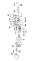
図8、12、14、16、17において、前記スイベルジョイント(旋回軸)5は、旋回軸心5Sと一致する軸心を有する筒体(固定側部材)141と、この筒体141内に軸心廻りに回転自在に上方から内嵌された中軸(可動側部材)143と、この中軸143の上部に設けられた円柱状の油路接続環体(可動側部材)144とを備えており、筒体141と中軸143の下部に通電手段145が設けられている。
筒体141は、走行体4の車体フレーム21にブラケット140を介して固定されていて走行体4側の油圧機器に接続されている。
8, 12, 14, 16, and 17, the swivel joint (swivel shaft) 5 includes a cylindrical body (fixed side member) 141 having an axis that coincides with the rotational axis 5 </ b> S, and a shaft within the cylindrical body 141. A center shaft (movable side member) 143 fitted from above to be rotatable around the center, and a cylindrical oil passage connecting ring (movable side member) 144 provided on the upper portion of the center shaft 143; An energizing means 145 is provided below the cylindrical body 141 and the central shaft 143.
The cylindrical body 141 is fixed to the vehicle body frame 21 of the traveling body 4 via a bracket 140 and is connected to hydraulic equipment on the traveling body 4 side.
中軸143及び油路接続環体144は、油路接続環体144の上面側に設けられた止め板142を介して旋回台6に対して廻り止めされていて、旋回台6と一体回転する。
油路接続環体144は、旋回台6側の油圧機器に接続されている。
筒体141の表面積は大きいので、該筒体141に接続される各種油圧ホース又は油圧配管等の油圧配管部材を接続する接続口は周方向及び軸方向に相互に適宜間隔をおいて設けられている。
この筒体141には、例えば、上からパイロット用接続口141j、静油圧式トランスミッション26に接続される静油圧式トランスミッション26用接続口141e、油圧信号用接続口141n、ブレーキ機構Aに接続されるブレーキ用接続口141h、ステアリング用油圧シリンダ71に接続されるパワーステアリングシリンダ71左用接続口141c及びパワーステアリングシリンダ71右用接続口141d、ドーザシリンダ78に接続されるドーザシリンダ78上昇用接続口141f及びドーザシリンダ78下降用接続口141b、旋回モータ15に接続される旋回モータ15右旋回用接続口141i及び旋回モータ15左旋回用接続口141g、後述する補助ポンプ185に接続される補助ポンプ185用接続口141k、油圧ポンプ85に接続されるメイン用接続口141m、作動油タンク17に接続されるドレン用接続口141t等が形成されている。
The middle shaft 143 and the oil passage connection ring 144 are prevented from rotating with respect to the swivel base 6 via a stop plate 142 provided on the upper surface side of the oil path connection ring 144, and rotate integrally with the swivel base 6.
The oil passage connection ring 144 is connected to the hydraulic equipment on the swivel base 6 side.
Since the surface area of the cylinder 141 is large, connection ports for connecting hydraulic piping members such as various hydraulic hoses or hydraulic pipes connected to the cylinder 141 are provided at appropriate intervals in the circumferential direction and the axial direction. Yes.
The cylindrical body 141 is connected to, for example, a pilot connection port 141j, a hydrostatic transmission 26 connection port 141e connected to the hydrostatic transmission 26, a hydraulic signal connection port 141n, and a brake mechanism A from above. A brake connection port 141h, a power steering cylinder 71 left connection port 141c connected to the steering hydraulic cylinder 71, a power steering cylinder 71 right connection port 141d, a dozer cylinder 78 ascending connection port 141f connected to the dozer cylinder 78, and Dozer cylinder 78 lowering connection port 141b, turning motor 15 connected to turning motor 15 turning right port 141i and turning motor 15 turning port 141g turning left, auxiliary pump 185 connected to auxiliary pump 185 described later Connection port 141k, hydraulic port The main connection port 141m which is connected to the flop 85, the drain connection port 141t and the like to be connected is formed in the hydraulic oil tank 17.
中軸143内には、前記筒体141に設けられた各接続口を径方向油路と軸方向油路とを介して油路接続環体144に接続する油路が形成されており、油路接続環体144には、それらの油路と連通する(筒体141に設けられた各接続口に連通する)油圧配管146が、筒体141に設けられた接続口に対応する本数設けられており、各油圧配管146は、筒体141に接続された走行体4側の油圧機器に対応する旋回台6側の各油圧機器に接続されている(後述する油圧回路参照)。
なお、中軸143と油路接続環体144とは一体的に形成されていてもよい。
An oil passage is formed in the middle shaft 143 to connect each connection port provided in the cylindrical body 141 to the oil passage connection ring 144 via the radial oil passage and the axial oil passage. The connection ring body 144 is provided with a number of hydraulic pipes 146 that communicate with those oil passages (communication with each connection port provided in the cylinder body 141) corresponding to the connection ports provided in the cylinder body 141. Each hydraulic pipe 146 is connected to each hydraulic device on the swivel base 6 side corresponding to the hydraulic device on the traveling body 4 side connected to the cylindrical body 141 (see a hydraulic circuit described later).
The middle shaft 143 and the oil passage connection ring 144 may be formed integrally.
前記油路接続環体144においては、筒体141に形成された接続口に対応する数の接続口を形成し、該接続口に接続される継手を介して油圧配管部材を接続することも可能であるが、そのようにすると筒体141と同様な接続口形成面積を必要とし、旋回台6内の狭いスペースに納められない、又は、旋回台6の上面であるステップ(フロア)が高くなるという問題がある。
そこで、本実施の形態にあっては、油路接続環体144の周囲に 油圧配管146を周方向に分散して配置し(たこ足状に配置し)、油路接続環体144の表面に各油圧配管146を直接的に溶着して一体化していて、油路接続環体144から油圧配管146が延設されており、この油圧配管146の先端側に備えられた継手部に、油路接続環体144を旋回台6側の油圧機器に接続するための油圧ホース、油圧配管等の油圧配管部材が接続される。
In the oil passage connection ring 144, it is possible to form a number of connection ports corresponding to the connection ports formed in the cylindrical body 141, and to connect the hydraulic piping members via joints connected to the connection ports. However, by doing so, a connection port forming area similar to that of the cylindrical body 141 is required, and it cannot be stored in a narrow space in the swivel base 6, or a step (floor) which is the upper surface of the swivel base 6 becomes high. There is a problem.
Therefore, in the present embodiment, the hydraulic pipes 146 are distributed in the circumferential direction around the oil passage connection ring 144 (arranged in a octopus shape), and are arranged on the surface of the oil path connection ring 144. Each hydraulic pipe 146 is directly welded and integrated, and the hydraulic pipe 146 extends from the oil path connecting ring 144, and the oil path is connected to a joint portion provided on the distal end side of the hydraulic pipe 146. A hydraulic piping member such as a hydraulic hose and hydraulic piping for connecting the connection ring 144 to the hydraulic equipment on the swivel base 6 side is connected.
この構成により、狭いスペースに油路接続環体144を収めることができ、狭いスペースで油路接続環体144に油圧配管部材を配管可能としている。
また、油路接続環体144の外周面に接続口(開口)を形成して、該接続口に継手を取り付け、該継手に油圧機器に接続するための油圧ホース等の油圧配管部材を接続するようにすると、油路接続環体144の油圧配管部材接続部分に油洩れ不良を生じる惧れがあるが、油圧配管146を油路接続環体144に直接溶接することにより、該油圧配管146と油圧接続環体144との間の油洩れ不良がなくなると共に、油圧配管146を油圧接続環体144から延設し、該油圧配管146の先端側に継手を介して油圧機器に接続するための油圧配管部材を接続するようにすることにより、油路接続環体144と、油路接続環体144を油圧機器に接続するための油圧配管部材とを比較的広い場所で接続でき、これにより、油圧配管146の先端側と、該油圧配管146を油圧機器に接続するための油圧配管部材とを油洩れ不良が生じないように確実に連結でき、また、油圧配管部材の組み付けも容易である。
With this configuration, the oil passage connection ring 144 can be stored in a narrow space, and the hydraulic piping member can be piped to the oil passage connection ring 144 in the narrow space.
Further, a connection port (opening) is formed on the outer peripheral surface of the oil passage connection ring 144, a joint is attached to the connection port, and a hydraulic piping member such as a hydraulic hose for connecting to a hydraulic device is connected to the joint. If this is done, there is a risk of oil leakage failure at the hydraulic piping member connection portion of the oil passage connection ring 144. However, by directly welding the hydraulic pipe 146 to the oil passage connection ring 144, Oil leakage between the hydraulic connecting ring 144 and the hydraulic pipe 146 is extended from the hydraulic connecting ring 144 and connected to a hydraulic device via a joint at the tip end of the hydraulic pipe 146. By connecting the piping member, the oil passage connecting ring 144 and the hydraulic piping member for connecting the oil passage connecting ring 144 to the hydraulic equipment can be connected in a relatively wide place, and thereby the hydraulic pressure is increased. The tip of the pipe 146 When, the hydraulic pipes 146 can be connected to the hydraulic piping member securely as oil leakage failure does not occur for connection to the hydraulic equipment, also it is easy assembly of hydraulic piping member.
また、この油路接続環体144は旋回軸受36から上方に突出して旋回台6内まで突入しており、特に旋回台6には左右立ち上がりリブ35もあって、油圧配管146を油路接続環体144から左右方向に突出する(延設する)のは困難であるので、各油圧配管146を途中からくの字に屈曲して前後に向くように形成している。
前記油圧配管(たこ足配管)146は上がりリブ35の上面以下に配置されており、旋回台6には油圧配管146を配置収容するための開口6aが形成されている。
前記中軸143の軸芯5Sには貫通孔147が形成され、ハーネス(通信用コード)148が挿通されており、中軸143の下面にはカップリング149が係合する係合凹部150が形成されている。
Further, the oil passage connection ring 144 protrudes upward from the swivel bearing 36 and enters the swivel base 6. In particular, the swivel base 6 has left and right rising ribs 35, and the hydraulic pipe 146 is connected to the oil path connection ring. Since it is difficult to protrude (extend) from the body 144 in the left-right direction, each hydraulic pipe 146 is formed to be bent in the shape of a letter from the middle and to face forward and backward.
The hydraulic pipe (octopus pipe) 146 is arranged below the upper surface of the rising rib 35, and an opening 6 a for arranging and accommodating the hydraulic pipe 146 is formed in the swivel base 6.
A through hole 147 is formed in the shaft core 5S of the middle shaft 143, a harness (communication cord) 148 is inserted, and an engagement recess 150 for engaging the coupling 149 is formed on the lower surface of the middle shaft 143. Yes.
筒体141の下部にはジョイントカバー151が着脱可能で且つ筒体141に対して旋回軸心5S廻りに回動不能に取付けられ、このジョイントカバー151の上側にケース体152が取付固定され、これらケース体152とジョイントカバー151との間に通電手段145が配置されている。
前記ジョイントカバー151及びケース体152側にはブラシ等の固定通電部材153が固定されており、この固定通電部材153は可動通電部材154と通電可能に摺接している。
A joint cover 151 is detachably attached to the lower portion of the cylindrical body 141 and is attached to the cylindrical body 141 so as not to be rotatable around the pivot axis 5S. A case body 152 is attached and fixed to the upper side of the joint cover 151. An energizing means 145 is disposed between the case body 152 and the joint cover 151.
A fixed energizing member 153 such as a brush is fixed to the joint cover 151 and the case body 152, and the fixed energizing member 153 is in sliding contact with the movable energizing member 154 so as to be energized.
この可動通電部材154は中軸143と同心でケース体152に回転自在に支持された回動軸155の下部に設けられており、この回動軸155のケース体152から突出した上部にカップリング149が装着され、このカップリング149が係合凹部150に挿入されて中軸143と係合することにより、回動軸155は中軸143と一体的に回転するように構成されている。
前記ハーネス148は一端が旋回台6上の操作機器(電気機器)に接続され、他端が回動軸155内に挿通されて可動通電部材154に接続されており、固定通電部材153を介して走行体4側のエンジン13及び各種電磁制御弁等の被操作機器に通信(通電)可能とされている。
The movable energizing member 154 is provided at the lower part of a rotating shaft 155 concentrically with the central shaft 143 and rotatably supported by the case body 152, and a coupling 149 is provided at the upper portion of the rotating shaft 155 protruding from the case body 152. The coupling shaft 149 is inserted into the engaging recess 150 and engaged with the middle shaft 143, so that the rotating shaft 155 rotates integrally with the middle shaft 143.
One end of the harness 148 is connected to an operating device (electrical device) on the swivel base 6, and the other end is inserted into the rotating shaft 155 and connected to the movable energizing member 154, via the fixed energizing member 153. Communication (energization) is possible with the engine 13 on the traveling body 4 side and the operated equipment such as various electromagnetic control valves.
本実施の形態では、前記通電手段145を介して旋回台6側から走行体4側に通信される電気信号としては、例えば、エンジン13の始動・停止用の指令信号、トランスミッション26の前後進切換え用の指令信号、トランスミッション16の高低速切換え用の指令信号、前後のドーザ10F、10Rの切換え用の指令信号、デフロックのON・OFF用の指令信号、スピードUP・DOWN用の指令信号等がある(後述する油圧回路参照)。
本実施の形態では、これらの電気信号を2本の回路148で処理できる多重通信システムが採用されている。
In the present embodiment, the electrical signals communicated from the swivel base 6 side to the traveling body 4 side via the energization means 145 include, for example, a start / stop command signal for the engine 13 and a forward / reverse switching of the transmission 26. Command signal for switching high / low speed of transmission 16, command signal for switching front and rear dozers 10F, 10R, command signal for ON / OFF of differential lock, command signal for speed up / down, etc. (Refer to the hydraulic circuit described later).
In this embodiment, a multiplex communication system that can process these electric signals by two circuits 148 is employed.
前記通電手段145は、主に制御信号用(通信用)の電気を通電するものであるが、モータ等を駆動する電力を供給するようにしてもよい。
通電手段145は、スイベルジョイント5の下部に設けられているので(油圧回路(上側)と電気回路(下側)とを上下方向2段重ねで構成したので)、スイベルジョイント5と通電手段145とを上下方向にコンパクトに構成できる。
図1、4〜7において、前記旋回台6の作業装置支持部37の上部には左右一対の支持体58が設けられている。この支持体58はコ字部材58Aから水平にパイプ製の横材58Bを突出した形状であり、コ字部材58Aが作業装置支持部37にボルト固定され、横材58Bが左右一対のロプス支持部を形成している。
The energization means 145 mainly energizes control signal (communication) electricity, but may supply electric power for driving a motor or the like.
Since the energizing means 145 is provided at the lower part of the swivel joint 5 (because the hydraulic circuit (upper side) and the electric circuit (lower side) are stacked in two vertical directions), the swivel joint 5 and the energizing means 145 Can be configured compactly in the vertical direction.
In FIGS. 1 and 4 to 7, a pair of left and right supports 58 are provided on the upper portion of the work device support portion 37 of the swivel base 6. The support body 58 has a shape in which a horizontal member 58B made of a pipe is horizontally projected from the U-shaped member 58A, the U-shaped member 58A is bolted to the work device support portion 37, and the horizontal member 58B is a pair of left and right lops support portions. Is forming.
前記運転席配置枠体51の左右横材51Bもロプス支持部を形成しており、前記前後に位置する横材51B及び横材58Bに左右各ロプス53の前後支柱52F、52Rが連結支持されている。
ロプス53は後支柱52Rから上部52Uまでが1本のパイプ材を略U字形状に曲げて形成され、上部52Uとパイプ製の前支柱52Fの上端とを連結しており、この左右ロプス53を複数本の連結杆60で連結し、かつ上部52Uに天蓋90を取付けて日除け可能に構成している。
The left and right horizontal members 51B of the driver seat frame 51 also form a lops support portion, and the front and rear columns 52F and 52R of the left and right lops 53 are connected to and supported by the horizontal members 51B and 58B positioned at the front and rear. Yes.
The LOPS 53 is formed by bending one pipe material into a substantially U shape from the rear strut 52R to the upper part 52U, and connects the upper part 52U and the upper end of the pipe front strut 52F. A plurality of connecting rods 60 are connected to each other, and a canopy 90 is attached to the upper portion 52U so as to be able to be shaded.
前後支柱52F、52Rの下端には連結部材59F、59Rが固着されている。この各連結部材59F、59Rは、パイプ又は中実棒状の連結部と、この連結部を支柱52に対して直角に配置するためのエルボ部とを有し、前記連結部を横材51B、58Bに挿入して、両者を貫通するボルトで止めることにより、ロプス53を旋回台6に対して装着するようになっている。
なお、連結部は横材51B、58Bに嵌合連結するように構成したり、両者を板材又はアングル材等で形成したりしてもよい。
Connecting members 59F and 59R are fixed to the lower ends of the front and rear columns 52F and 52R. Each of the connecting members 59F and 59R has a pipe or solid bar-like connecting portion and an elbow portion for arranging the connecting portion at a right angle to the support column 52. The connecting portions are used as the cross members 51B and 58B. Are inserted into the two and stopped with a bolt that penetrates both of them, so that the lops 53 are attached to the swivel base 6.
The connecting portion may be configured to be fitted and connected to the cross members 51B and 58B, or both may be formed of a plate material or an angle material.
前記左右後支柱52RはL字状に屈曲されており、旋回台6の後壁部34から運転席7の後上方へ立ち上がり、中途部から上方へ延設されていて、運転席配置枠体51と共にエンジン13の上方へ張り出した形状に形成している。
運転席配置枠体51及び運転席7はエンジン13よりも高い位置に配置され、旋回台6の旋回時にエンジン13の上方を通過可能、即ち、走行体4の最高位置である嵩高形状部4Bの上方を通過可能にしている。
前記エンジン13を走行体4の後部に搭載し、運転席7を旋回台6から後上方へ張り出した位置に配置することにより、旋回台6上では運転席7が後部に位置しかつ操縦装置8が前部に位置し、上部構造体11の重量は極めて軽くなり、前後寸法は必要最小限の寸法となる。
The left and right rear struts 52R are bent in an L shape, rise from the rear wall portion 34 of the swivel base 6 to the rear upper side of the driver's seat 7, and extend upward from the midway portion. In addition, it is formed in a shape projecting upward from the engine 13.
The driver's seat arrangement frame 51 and the driver's seat 7 are arranged at a position higher than the engine 13 and can pass above the engine 13 when the swivel base 6 turns, that is, the bulky shape portion 4B which is the highest position of the traveling body 4 The upper part is allowed to pass.
The engine 13 is mounted on the rear part of the traveling body 4 and the driver's seat 7 is disposed at a position protruding rearward and upward from the swivel base 6, so that the driver's seat 7 is located at the rear part on the swivel base 6 and the control device 8. Is located at the front, the weight of the upper structure 11 is extremely light, and the front and rear dimensions are the minimum necessary dimensions.
そして、運転席7の前方の旋回台6上を居住空間として有効に利用でき、旋回台6の占有面積を小さくかつ低位置に配置して、作業機1を前後・左右・上下方向においてコンパクトに構成することを可能にしている。
前記操縦装置8は高速路上走行ができるようにハンドル73を有し、ハンドル73のステアリングコントローラ73A及びその他の機器は旋回台6の作業装置支持部37の後側に立設した支持体38に装着されていて、1組のアッセンブリとして組み立てて旋回台6上に装備できるようになっている。
Further, the swivel base 6 in front of the driver's seat 7 can be effectively used as a living space, the occupation area of the swivel base 6 is small and arranged at a low position, and the work implement 1 is compact in the front-rear, left-right, and vertical directions. Making it possible to configure.
The steering device 8 has a handle 73 so that it can travel on a high-speed road, and a steering controller 73A of the handle 73 and other devices are mounted on a support 38 standing on the rear side of the work device support portion 37 of the swivel base 6. It can be assembled on a swivel base 6 as a set of assemblies.
即ち、前記支持体38は、図18〜20に示すように、ステアリングコントローラ73Aの他に、静油圧式トランスミッション26を変速操作する変速ペダル94が右足置き位置近傍に配置されるように枢支され、その近傍にブレーキペダル91が枢支され、ブレーキ機構Aを操作するためのマスタシリンダ101、オイルタンク102が装着され、変速ペダル94用のダンパ103及びHST用のリモコン弁104等も装着されている。
前記ハンドル73のハンドルポスト73Bには、前後進切換弁174を操作するシャトルレバー105が沿って配置されている。
That is, as shown in FIGS. 18 to 20, the support body 38 is pivotally supported so that a shift pedal 94 for shifting the hydrostatic transmission 26 is arranged in the vicinity of the right foot rest position in addition to the steering controller 73A. In the vicinity thereof, a brake pedal 91 is pivotally supported, a master cylinder 101 for operating the brake mechanism A and an oil tank 102 are mounted, a damper 103 for a shift pedal 94, a remote control valve 104 for HST, and the like are also mounted. Yes.
A shuttle lever 105 for operating the forward / reverse switching valve 174 is disposed on the handle post 73 </ b> B of the handle 73.
図21、図22はホイール式作業機1の油圧回路を示しており、スイベルジョイント5を境にして走行体4側と上部構造体11側とに分かれている。
エンジン13の動力はトランスミッション26のポンプ81を駆動すると同時にチャージポンプ109も駆動し、さらに、減速ギヤ群107及び油圧クラッチ110を介して油圧ポンプ85を駆動可能にしている。
トランスミッション26においては、シャトル弁170とパイロット操作弁171とが設けられ、パイロット操作弁171等は高低切換弁169によって操作可能であり、モータ82の斜板制御アクチュエータ172を作動して高速状態と低速状態とに切り換え可能になっている。
21 and 22 show the hydraulic circuit of the wheel type work machine 1, which is divided into the traveling body 4 side and the upper structure 11 side with the swivel joint 5 as a boundary.
The power of the engine 13 drives the pump 81 of the transmission 26 and simultaneously drives the charge pump 109, and further allows the hydraulic pump 85 to be driven via the reduction gear group 107 and the hydraulic clutch 110.
In the transmission 26, a shuttle valve 170 and a pilot operation valve 171 are provided. The pilot operation valve 171 and the like can be operated by a high / low switching valve 169, and a swash plate control actuator 172 of the motor 82 is operated to operate at high speed and low speed. It is possible to switch to the state.
ポンプ81には前後進及び速度を切り換えるスピードアクチュエータ173が接続され、このスピードアクチュエータ173はスピード作動弁176で制御され、このスピード作動弁176は前後進切換弁174で前後切換操作されると共に、変速ペダル94によって操作されるリモコン弁104で制御可能になっている。
チャージポンプ109からの作動油は走行ロック切換弁175を通ってリモコン弁104に至り、このリモコン弁104から前後進切換弁174の前後一方へ供給され、変速ペダル94の踏み込み量に応じてスピード作動弁176が作動してスピードアクチュエータ173を制御する。
The pump 81 is connected to a speed actuator 173 for switching forward and backward and speed. The speed actuator 173 is controlled by a speed operating valve 176, and the speed operating valve 176 is operated to switch forward and backward by a forward and backward switching valve 174. The remote control valve 104 operated by the pedal 94 can be controlled.
The hydraulic oil from the charge pump 109 passes through the travel lock switching valve 175 to the remote control valve 104, and is supplied from the remote control valve 104 to one of the front and rear of the forward / reverse switching valve 174, and operates at a speed according to the depression amount of the shift pedal 94. Valve 176 is actuated to control speed actuator 173.
177はデフロックであり、チャージポンプ109からの作動油をデフロック切換弁178でオン・オフ操作して、デフロック作動状態と解除状態とに切り換える。
油圧ポンプ85からの作動油はコントロールバルブ56に供給され、このコントロールバルブ56の各油圧制御弁56a〜gからそれぞれのアクチュエータへ送られる。
前記油圧ポンプ85には補助ポンプ185が連接されており、この補助ポンプ185の作動油は油圧モータ158へ供給され、その後ステアリングコントローラ73Aを経て、ステアリング用油圧シリンダ71へ供給される。
Reference numeral 177 denotes a diff lock, and the hydraulic oil from the charge pump 109 is turned on / off by the diff lock switching valve 178 to switch between the diff lock operation state and the release state.
The hydraulic oil from the hydraulic pump 85 is supplied to the control valve 56, and is sent from the hydraulic control valves 56a to 56g of the control valve 56 to the respective actuators.
An auxiliary pump 185 is connected to the hydraulic pump 85, and hydraulic fluid of the auxiliary pump 185 is supplied to the hydraulic motor 158, and then supplied to the steering hydraulic cylinder 71 via the steering controller 73A.
前記トランスミッション26、旋回モータ15、ポンプ109、85、185、ステアリング用油圧シリンダ71、ドーザシリンダ78、走行ロック切換弁175、切換弁集合体54等は走行体4側に配置され、操作装置55、変速ペダル94、ステアリングコントローラ73A、3本の操作レバー181、182、183、油圧モータ158、コントロールバルブ56等は上部構造体11側に配置され、スイベルジョイント5を介して上下の作動油の供給、排出を可能にしており、スイベルジョイント5の通電手段145を介して、上部構造体11側から走行体4側へのトランスミッション26制御用電磁弁及びその他の電磁弁、電気機器への制御信号を送信するようになっている。
The transmission 26, the turning motor 15, the pumps 109, 85, 185, the steering hydraulic cylinder 71, the dozer cylinder 78, the travel lock switching valve 175, the switching valve assembly 54, etc. are disposed on the traveling body 4 side, and the operation device 55, A shift pedal 94, a steering controller 73A, three operation levers 181, 182, 183, a hydraulic motor 158, a control valve 56, and the like are disposed on the upper structure 11 side, and supply of upper and lower hydraulic oil via the swivel joint 5; Discharge is possible, and a control signal is transmitted from the upper structure 11 side to the traveling body 4 side through the energizing means 145 of the swivel joint 5 to control the transmission 26 and other solenoid valves and electrical equipment. It is supposed to be.
前記切換弁集合体54は、図27に示すように、前記前後進切換弁174、走行ロック切換弁175、デフロック切換弁178、高低切換弁169、前後ドーザ切換弁197及びステアリング操舵方向切換弁178によって構成されており、これら切換弁174,175,178,169,197,178は電磁弁によって構成されている。
前後進切換弁174は左側に配置され、走行ロック切換弁175は右側の後側に配置され、デフロック切換弁178及び高低切換弁169は右側の前側に配置され、前後ドーザ切換弁197は左右方向中央の後側に配置され、ステアリング操舵方向切換弁178は左右方向中央の前側に配置されされている。
As shown in FIG. 27, the switching valve assembly 54 includes the forward / reverse switching valve 174, the travel lock switching valve 175, the differential lock switching valve 178, the high / low switching valve 169, the front / rear dozer switching valve 197, and the steering steering direction switching valve 178. These switching valves 174, 175, 178, 169, 197, 178 are constituted by electromagnetic valves.
The forward / reverse switching valve 174 is disposed on the left side, the travel lock switching valve 175 is disposed on the rear side on the right side, the differential lock switching valve 178 and the height switching valve 169 are disposed on the front side on the right side, and the front / rear dozer switching valve 197 is in the left-right direction. The steering steering direction switching valve 178 is disposed on the front side of the center in the left-right direction.
前記前後ドーザ切換弁197は、ドーザシリンダ78制御用の油圧制御弁56gによって、前後一方のドーザ10F,10Rのドーザシリンダ78を選択的に制御するように回路を切り換えるものであり、ステアリング操舵方向切換弁178はハンドル操舵方向と走行体4の旋回方向が同じ状態と、ハンドル操舵方向と走行体4の旋回方向が反対である状態とに回路を切り換えるものである。
また、切換弁集合体54は、前車軸ケース63Fの後方側で、車体フレームの左右の側部フレーム22間に亘る取付板50に取り付けられていて、前車軸ケース63Fの上方側で且つ左右の側部フレーム22の間に配置されており、切換弁集合体54の上方空間は開放状である(切換弁集合体54の上方には、邪魔物がない)ので、該切換弁集合体54の構成体である各切換弁174,175,178,169,197,178のメンテナンス性の向上が図られていると共に、前車軸ケース63F及び左右側部フレーム22等によって切換弁集合体54の保護が図られている。
The front / rear dozer switching valve 197 switches a circuit so as to selectively control the dozer cylinder 78 of one of the front / rear dozers 10F, 10R by a hydraulic control valve 56g for controlling the dozer cylinder 78. The valve 178 switches the circuit between a state in which the steering direction of the steering wheel and the turning direction of the traveling body 4 are the same and a state in which the steering direction of the steering wheel and the turning direction of the traveling body 4 are opposite.
The switching valve assembly 54 is attached to the mounting plate 50 between the left and right side frames 22 of the vehicle body frame on the rear side of the front axle case 63F, and on the upper side of the front axle case 63F and on the left and right sides. Since it is disposed between the side frames 22 and the upper space of the switching valve assembly 54 is open (there is no obstruction above the switching valve assembly 54), The maintainability of each switching valve 174, 175, 178, 169, 197, 178, which is a component, is improved, and the switching valve assembly 54 is protected by the front axle case 63F, the left and right side frames 22, and the like. It is illustrated.
なお、切換弁集合体54の配置空間の上面側を着脱自在なカバー体によって覆うようにするのがよい。
前述したホイール式作業機1は、各構成部分の総てを備えていることが好ましいが、部分的に選択採用したり、適宜組み合わせたりすることができる。
例えば、前後4輪2、3を有する走行体4に走行駆動装置12及びドーザ10とを備え、走行体4の最高位置よりも低位置に全周旋回可能に旋回台6を設け、この旋回台6上に運転席7及び操縦装置8を有する上部構造体11と対地作業装置9とを備えて基本構成を作り、
(a)旋回台6に搭載した上部構造体11及び対地作業装置9をエンジン13上方通過可能にする、
(b)走行体4は旋回台6の下方部分が扁平形状部4Aでかつ旋回台6の後方部分が嵩高形状部4Bな構造にする、
(c)走行体4の後部にエンジン13を配置し、旋回台6をエンジン13上端より下位に配置する、
(d)旋回軸受36及び旋回台6の内の少なくとも旋回軸受36を、前後輪2、3間でかつその少なくとも一方の上端よりも低い位置に配置する、
(e)作業装置支持部37を旋回台6の外周の略範囲内に配置する、
(f)運転席7を旋回台6から後方向に突出させる、
(g)作業装置支持部37によって支持されている対地作業装置9の基部を前後輪2、3及びエンジン13より高位置に配置する、
等構成の少なくとも1つを備えさせることができる。
In addition, it is preferable to cover the upper surface side of the arrangement space of the switching valve assembly 54 with a detachable cover body.
The wheel-type working machine 1 described above preferably includes all of the components, but can be partially selected and used or can be appropriately combined.
For example, a traveling body 4 having front and rear four wheels 2 and 3 is provided with a traveling drive device 12 and a dozer 10, and a swivel base 6 is provided at a position lower than the highest position of the traveling body 4 so as to be capable of turning all around. 6 is provided with an upper structure 11 having a driver's seat 7 and a control device 8 and a ground work device 9, and a basic configuration is made.
(A) The upper structure 11 and the ground work device 9 mounted on the swivel base 6 are allowed to pass above the engine 13.
(B) The traveling body 4 has a structure in which the lower part of the swivel base 6 is a flat part 4A and the rear part of the swivel base 6 is a bulky part 4B.
(C) The engine 13 is disposed at the rear part of the traveling body 4, and the swivel base 6 is disposed below the upper end of the engine 13.
(D) At least the swivel bearing 36 of the swivel bearing 36 and the swivel base 6 is disposed between the front and rear wheels 2 and 3 and at a position lower than the upper end of at least one of the front and rear wheels 2 and 3.
(E) The work device support part 37 is disposed within a substantially outer periphery of the swivel base 6.
(F) The driver's seat 7 protrudes backward from the swivel base 6;
(G) The base portion of the ground work device 9 supported by the work device support portion 37 is disposed at a higher position than the front and rear wheels 2, 3 and the engine 13.
At least one of equal configurations may be provided.
また、それらの構成に、
(h)走行体4の左右一側に燃料タンク16を、左右他側に作動油タンク17、バッテリー18をそれぞれ装備する、
(j)走行体4の車体フレーム21をラダー構造にして前後輪2、3を縣架する、
(k)走行体4の上面に前部の作業装置支持部37、後部の後壁部34及びそれらを繋ぐ左右立上りリブ35を一体立設する、
(m)走行体4の嵩高形状部4Bにエンジン13を配置し、扁平形状部4Aに動力伝達機構14を配置する、
(n)動力伝達機構14に静油圧式トランスミッション26及び減速装置87を組み合わせて使用し、このトランスミッション26の入力軸27、出力軸28及び推進軸114を略前後方向に沿わせかつ左右方向に分離配置する、
(p)旋回軸受36及び旋回台6の内の少なくとも旋回軸受36を、前後輪2、3間でかつ前後輪2、3の少なくとも一方の上端よりも低い位置に配置する、
(q)旋回台6を後部がエンジン13に近接し、前部を前輪2と前後方向にオーバラップさせる、
(r)旋回台6を平面視略円形状に形成する、
(s)作業装置支持部37でスイング軸39を支持し、このスイング軸39にスイングシリンダ41で揺動されるスイング体40を枢支し、このスイング体40に横軸48を介してブーム42及びこのブーム42を昇降するブームシリンダ43を枢支する、
(t)スイング体40、ブーム42及びブームシリンダ43を走行体4の最高位置の上方を通過可能な高さに設定する、
(u)スイング体40の前部を旋回台6から径外方向に突出させる、
(w)前記対地作業装置用の操作装置は、油圧装置の切換弁のいくつかを制御する油圧制御弁と、この油圧制御弁を操作する手動操作手段と、油圧装置の切換弁のいくつかを制御するフート操作手段とを有する、
(x)旋回台6上に運転席配置枠体51を設け、この運転席配置枠体51の後部を旋回台6から後方へ張り出し、その後方張り出し部に運転席7及び操作装置55を配置し、この運転席7及び操作装置55を旋回台6の旋回時に走行体4の上方を通過可能にする、
(y)前部の作業装置支持部37及び後部の運転席配置枠体51のそれぞれに横材58B.51Bを設け、前後横材58B,51Bにロプス53の前後下端を連結し、ロプス53の上部間に天蓋90を設ける、
(z)ドーザ10を走行体4の前後両方に装着する。
Also, in their configuration,
(H) The fuel tank 16 is provided on the left and right sides of the traveling body 4, and the hydraulic oil tank 17 and the battery 18 are provided on the left and right sides, respectively.
(J) The body frame 21 of the traveling body 4 has a ladder structure and the front and rear wheels 2 and 3 are suspended.
(K) A front working device support portion 37, a rear rear wall portion 34, and left and right rising ribs 35 connecting them are integrally provided on the upper surface of the traveling body 4.
(M) The engine 13 is disposed in the bulky shape portion 4B of the traveling body 4, and the power transmission mechanism 14 is disposed in the flat shape portion 4A.
(N) The hydrostatic transmission 26 and the speed reducer 87 are used in combination with the power transmission mechanism 14, and the input shaft 27, the output shaft 28, and the propulsion shaft 114 of the transmission 26 are substantially aligned in the front-rear direction and separated in the left-right direction. Deploy,
(P) At least the swivel bearing 36 of the swivel bearing 36 and the swivel base 6 is disposed between the front and rear wheels 2 and 3 and at a position lower than the upper end of at least one of the front and rear wheels 2 and 3.
(Q) The rear part of the turntable 6 is close to the engine 13 and the front part overlaps the front wheel 2 in the front-rear direction.
(R) The swivel base 6 is formed in a substantially circular shape in plan view.
(S) A swing shaft 39 is supported by the work device support portion 37, a swing body 40 that is swung by a swing cylinder 41 is pivotally supported on the swing shaft 39, and a boom 42 is supported on the swing body 40 via a horizontal shaft 48. And a boom cylinder 43 that lifts and lowers the boom 42 is pivotally supported.
(T) The swing body 40, the boom 42, and the boom cylinder 43 are set to a height at which the swing body 40, the boom cylinder 43, and the upper position of the traveling body 4 can pass.
(U) The front part of the swing body 40 is protruded radially outward from the swivel base 6;
(W) The operating device for the ground work device includes a hydraulic control valve for controlling some of the switching valves of the hydraulic device, a manual operating means for operating the hydraulic control valve, and some of the switching valves of the hydraulic device. Foot control means to control,
(X) A driver seat arrangement frame 51 is provided on the swivel base 6, and the rear portion of the driver seat arrangement frame 51 projects rearward from the swivel base 6, and the driver seat 7 and the operation device 55 are arranged on the rear projecting portion. The driver's seat 7 and the operation device 55 are allowed to pass above the traveling body 4 when the swivel base 6 is turned.
(Y) The cross members 58B... Are respectively attached to the front work device support portion 37 and the rear driver seat arrangement frame body 51. 51B is provided, the front and rear lower ends of the lops 53 are connected to the front and rear cross members 58B and 51B, and the canopy 90 is provided between the upper portions of the lops 53.
(Z) The dozer 10 is mounted on both the front and rear of the traveling body 4.
さらに、ホイール式作業機1の前記基本構成を、前後輪2、3を有する走行体4の重量に対して、旋回台6、運転席7、操縦装置8及び対地作業装置9の内の少なくとも旋回台6、運転席7及び操縦装置8の総重量を軽く設定するという構成等を付加した場合でも、また、上部構造体11の旋回軸5から後端までの距離L1を旋回軸5から後輪3の後端までの距離L2以内に略納めた構成等を付加した場合でも、前記組み合わせを同様に行うことができる。
上記ホイール式作業機1は、スキッドステアローダが不得手な傾斜地や狭い現場でグレーディング作業を効率よく行うのに適しており、動きながら土をかき寄せるという作業もできるが、止まった状態で油圧を利用して土をかき寄せるという作業のやり方を得意とし、幅違いの作業具46を付け替えて、運搬作業と電線埋設等の1.8m以下の溝掘削作業との両方を1台で行える。
Further, the basic configuration of the wheel type work machine 1 is set to at least turn among the swivel base 6, the driver's seat 7, the control device 8 and the ground work device 9 with respect to the weight of the traveling body 4 having the front and rear wheels 2 and 3. Even when a configuration in which the total weight of the platform 6, the driver's seat 7 and the control device 8 is set lightly is added, the distance L1 from the turning shaft 5 to the rear end of the upper structure 11 is set to the rear wheel. Even when a configuration or the like that is substantially within the distance L2 to the rear end of 3 is added, the combination can be performed in the same manner.
The wheel type work machine 1 is suitable for efficiently performing grading work on sloping terrain where the skid steer loader is not good, or in a narrow field, and can also work to scrape the soil while moving, We are good at working methods of scraping soil by using it, and by changing work tools 46 of different widths, both transportation work and groove excavation work of 1.8 m or less such as electric wire burial can be performed with one unit.
即ち、整地工事のうち機械を使う作業を大きく分けると運搬とグレーディングとがあり、ホイール式作業機1は、地面に勾配やうねりをつける、水平にする、土をかき寄せる、溝や穴を埋め戻す等、運搬以外の土移動作業であるグレーディング作業を特に効率よく行える。
なお、本発明は前記実施形態における各部材の形状及びそれぞれの前後・左右・上下の位置関係は、図1〜27に示すように構成することが最良である。しかし、前記実施形態に限定されるものではなく、部材、構成を種々変形したり、組み合わせを変更したりすることもできる。
In other words, the work using the machine in leveling work is roughly divided into transportation and grading. The wheel type work machine 1 is inclined and swelled on the ground, leveled, scraped the soil, filled with grooves and holes. Grading work that is soil transfer work other than transportation, such as returning, can be performed particularly efficiently.
In the present invention, the shape of each member and the positional relationship between the front, back, left, and right in the above embodiment are best configured as shown in FIGS. However, it is not limited to the said embodiment, A member, a structure can be variously deformed, and a combination can also be changed.
例えば、左右のロプス53を相互に連結してなる4柱式ロプス装置の代わりに2柱式ロプス装置又はキャビン装置を搭載したり、操作装置55をハンドル73の近傍に配置したり、従動輪をホイール式にし、駆動輪をクローラ装置に置き換えたりしてもよい。
また、以上詳述した本実施の形態の作業機1にあっては、旋回台6を走行体4の最高位置よりも低位置に配置して旋回台6を全周旋回可能にし、走行体4の重量を重くしかつその上側の重量を軽減し、かつ、対地作業装置9を旋回台6の前側で支持しかつ左右揺動させることができる上に、走行安定性、対地作業安定性、旋回作業性、上下寸法のコンパクト化、前後寸法のコンパクト化、乗降容易化、居住空間の確保又は構成の簡素化等ができるものである。
For example, instead of a four-column type ropse device that connects the left and right ropses 53 to each other, a two-column type ropse device or a cabin device is mounted, the operating device 55 is arranged in the vicinity of the handle 73, or a driven wheel is installed. A wheel type may be used, and the driving wheel may be replaced with a crawler device.
Further, in the working machine 1 according to the present embodiment described in detail above, the swivel base 6 is disposed at a position lower than the highest position of the traveling body 4 so that the swivel base 6 can be swung around the entire circumference. The ground work device 9 can be supported on the front side of the turntable 6 and can be swung to the left and right, and the running stability, ground work stability, and turning can be increased. Workability, downsizing and downsizing, downsizing and downsizing, ease of getting on and off, securing of living space or simplification of configuration can be achieved.