EP1506902A2 - Load transport assembly - Google Patents
Load transport assembly Download PDFInfo
- Publication number
- EP1506902A2 EP1506902A2 EP04019075A EP04019075A EP1506902A2 EP 1506902 A2 EP1506902 A2 EP 1506902A2 EP 04019075 A EP04019075 A EP 04019075A EP 04019075 A EP04019075 A EP 04019075A EP 1506902 A2 EP1506902 A2 EP 1506902A2
- Authority
- EP
- European Patent Office
- Prior art keywords
- load
- drive
- transport assembly
- transfer device
- load transport
- Prior art date
- Legal status (The legal status is an assumption and is not a legal conclusion. Google has not performed a legal analysis and makes no representation as to the accuracy of the status listed.)
- Withdrawn
Links
- 230000003019 stabilising effect Effects 0.000 claims abstract description 10
- 230000008878 coupling Effects 0.000 claims abstract description 9
- 238000010168 coupling process Methods 0.000 claims abstract description 9
- 238000005859 coupling reaction Methods 0.000 claims abstract description 9
- 238000000034 method Methods 0.000 description 2
- 235000004443 Ricinus communis Nutrition 0.000 description 1
- 238000010276 construction Methods 0.000 description 1
- 238000012986 modification Methods 0.000 description 1
- 230000004048 modification Effects 0.000 description 1
Images

Classifications
-
- B—PERFORMING OPERATIONS; TRANSPORTING
- B66—HOISTING; LIFTING; HAULING
- B66F—HOISTING, LIFTING, HAULING OR PUSHING, NOT OTHERWISE PROVIDED FOR, e.g. DEVICES WHICH APPLY A LIFTING OR PUSHING FORCE DIRECTLY TO THE SURFACE OF A LOAD
- B66F5/00—Mobile jacks of the garage type mounted on wheels or rollers
- B66F5/04—Mobile jacks of the garage type mounted on wheels or rollers with fluid-pressure-operated lifting gear
-
- B—PERFORMING OPERATIONS; TRANSPORTING
- B60—VEHICLES IN GENERAL
- B60P—VEHICLES ADAPTED FOR LOAD TRANSPORTATION OR TO TRANSPORT, TO CARRY, OR TO COMPRISE SPECIAL LOADS OR OBJECTS
- B60P3/00—Vehicles adapted to transport, to carry or to comprise special loads or objects
- B60P3/12—Vehicles adapted to transport, to carry or to comprise special loads or objects for salvaging damaged vehicles
- B60P3/125—Vehicles adapted to transport, to carry or to comprise special loads or objects for salvaging damaged vehicles by supporting only part of the vehicle, e.g. front- or rear-axle
- B60P3/127—Vehicles adapted to transport, to carry or to comprise special loads or objects for salvaging damaged vehicles by supporting only part of the vehicle, e.g. front- or rear-axle on a tow dolly
-
- B—PERFORMING OPERATIONS; TRANSPORTING
- B62—LAND VEHICLES FOR TRAVELLING OTHERWISE THAN ON RAILS
- B62B—HAND-PROPELLED VEHICLES, e.g. HAND CARTS OR PERAMBULATORS; SLEDGES
- B62B5/00—Accessories or details specially adapted for hand carts
- B62B5/0026—Propulsion aids
-
- B—PERFORMING OPERATIONS; TRANSPORTING
- B62—LAND VEHICLES FOR TRAVELLING OTHERWISE THAN ON RAILS
- B62B—HAND-PROPELLED VEHICLES, e.g. HAND CARTS OR PERAMBULATORS; SLEDGES
- B62B5/00—Accessories or details specially adapted for hand carts
- B62B5/0083—Wheeled supports connected to the transported object
-
- B—PERFORMING OPERATIONS; TRANSPORTING
- B62—LAND VEHICLES FOR TRAVELLING OTHERWISE THAN ON RAILS
- B62D—MOTOR VEHICLES; TRAILERS
- B62D51/00—Motor vehicles characterised by the driver not being seated
- B62D51/04—Motor vehicles characterised by the driver not being seated the driver walking
-
- B—PERFORMING OPERATIONS; TRANSPORTING
- B62—LAND VEHICLES FOR TRAVELLING OTHERWISE THAN ON RAILS
- B62D—MOTOR VEHICLES; TRAILERS
- B62D53/00—Tractor-trailer combinations; Road trains
- B62D53/04—Tractor-trailer combinations; Road trains comprising a vehicle carrying an essential part of the other vehicle's load by having supporting means for the front or rear part of the other vehicle
- B62D53/08—Fifth wheel traction couplings
- B62D53/0857—Auxiliary semi-trailer handling or loading equipment, e.g. ramps, rigs, coupling supports
-
- B—PERFORMING OPERATIONS; TRANSPORTING
- B62—LAND VEHICLES FOR TRAVELLING OTHERWISE THAN ON RAILS
- B62B—HAND-PROPELLED VEHICLES, e.g. HAND CARTS OR PERAMBULATORS; SLEDGES
- B62B2202/00—Indexing codes relating to type or characteristics of transported articles
- B62B2202/90—Vehicles
-
- B—PERFORMING OPERATIONS; TRANSPORTING
- B62—LAND VEHICLES FOR TRAVELLING OTHERWISE THAN ON RAILS
- B62B—HAND-PROPELLED VEHICLES, e.g. HAND CARTS OR PERAMBULATORS; SLEDGES
- B62B5/00—Accessories or details specially adapted for hand carts
- B62B5/0026—Propulsion aids
- B62B5/0033—Electric motors
- B62B5/0036—Arrangements of motors
- B62B5/0043—One motor drives one wheel
Definitions
- the invention relates to a load transport assembly and in particular to a pedestrian operated powered load transport assembly adapted for towing large heavy items such as for example articulated lorry trailers.
- Powered tugs which can be used to transport loads under the control of a pedestrian operator are also know, such as that described in the Applicant's UK patent No. GB2279934B, but none are available which can transport loads of the size of a articulated lorry trailer with sufficient manoeuvrability for the confined spaces of such yards.
- a load transport assembly having:
- the load transfer device is hydraulically operated.
- the load transport device may conveniently further includes batteries, mounted in the central region of the body, to power the drive means and load transfer device.
- the drive wheels are larger than the ground engaging stabilising wheels.
- control means is constructed and arranged for use by a pedestrian operator.
- a load transport device When a load transport device according to the invention is specifically adapted to transport trailers having air brakes it further includes a pressurised air system for coupling to and operation of the trailer air brakes.
- a load transport assembly 10 (herein after referred to as a tractor) having a body 12 comprising a front region 14, a rear region 16 and a central region 18.
- the front region 14 of the body 12 includes a load transfer device 20, drive means in the form of two electric motors 22 a and 22 b , and a main support wheel assembly 24.
- the load transfer device is fully described in the Applicant's earlier UK patent application No. GB0307785.6 and European patent application No. EP03007688.9 and therefore will not be described in detail here.
- a coupling 26 for receiving a hitch member of a vehicle trailer to be transported by the tractor 10, and lifting means in the form of a hydraulic ram (not shown) operable by means of a hydraulic system 28 to raise and lower the coupling 26 on a principle axis X as shown in Figures 3 to 5.
- the main support wheel assembly 24 comprises an axle 30 extending laterally of the front region 14 of the body 12 with, rotatably mounted on each end, a main support wheel 32 a and 32 b respectively.
- the main support wheel 32 a is driven by electric motor 22 a whilst the main support wheel 32 b is driven by electric motor 22 b , and thus are controllable completely independently of each other.
- the central region 18 of the body 12 includes a main frame 34 surrounding a battery container 36 inside which are located batteries (not shown) which power the electric motors 22 and the hydraulic system 28.
- the rear region 16 of the body 12 includes a lower frame portion 38 extending rearwardly and upwardly from a lower part of the main frame 34, and an upper frame portion 40 extending rearwardly and downwardly from an upper part of the main frame 34 to join the lower frame portion 38 part way along it's length at a point below which two ground engaging stabilising wheels 42 are mounted for rotation around horizontal and vertical axes.
- the lower frame portion 38 extends rearwardly beyond the two ground engaging stabilising wheels 42, and at it's rearward end a handle 44 is pivotally mounted on a horizontal axis. At its distal end the handle 44 carries a grip portion 46 bearing controls (not shown) for control of the load transfer device 20 and the driving of the main support wheels 32.
- the rear region 16 also includes, located between the lower and upper frame portions 38, 40, a pressurised air system 48 for connection to and operation of the air brakes of the vehicle trailer to be transported by the load transport assembly 10.
- the tractor 10 is specifically adapted for transport of articulated lorry trailers of the kind having non-steering wheels at their rear end and a hitch and legs at their front end.
- the trailers When the trailers are connected to a lorry cab unit via the hitch the legs are folded up underneath the trailer, but when no lorry cab is connected to the trailer via the hitch the legs are down and the trailer stands on the legs at the front and the wheels at the rear.
- the tractor 10 is operated as follows. With all four wheels 22, 42 on the ground the pedestrian operator uses the controls to drive it into position relative to the trailer to be transported, that is into a position with the coupling 26 of the load transfer device 20 located directly beneath a hitch part of the trailer at the front end thereof. The load transfer device 20 is then raised up, using the controls, underneath the hitch part until the weight of the front part of the trailer is taken off it's legs and onto the load transfer device 20. As the load transfer device 20 is located with it's principle axis X above the centre of the axle 30 the load is thus transferred to the main support wheels 32 of the tractor 10.
- the action of transferring the weight in this way may also lift the ground engaging stabilising wheels 42 off the ground, such that only the main support wheels 32 are thus on the ground, although they may simply have the majority of the weight taken off them but remain in contact with the ground.
- the trailer air brakes are connected to the pressurised air system 48 such that they can be released to enable the trailer to be moved.
- the pedestrian operator then operates the controls to drive the main support wheels 32 as necessary to move the trailer to it's next location.
- the control of the two electric motors 22 is entirely independent such that the wheels 32 can be driven at different speeds and in different directions simultaneously in order to steer the tractor 10 as required.
- the tractor rotates about the principle axis X of the load transfer device, but if they are driven in the same direction and at the same speed the tractor 10 moves in a straight line.
- Combinations, of speed and relative direction of drive of the wheels 32, in between these two extremes mean that the tractor 10 is very manoeuvrable thus enabling the trailers to be moved around crowded goods yards more easily than has previously been possible, and furthermore by a pedestrian operator rather than a qualified heavy goods vehicle driver.
Landscapes
- Engineering & Computer Science (AREA)
- Mechanical Engineering (AREA)
- Transportation (AREA)
- Chemical & Material Sciences (AREA)
- Combustion & Propulsion (AREA)
- Health & Medical Sciences (AREA)
- Public Health (AREA)
- Life Sciences & Earth Sciences (AREA)
- Geology (AREA)
- Structural Engineering (AREA)
- Vehicle Body Suspensions (AREA)
- Tires In General (AREA)
Abstract
Description
- The invention relates to a load transport assembly and in particular to a pedestrian operated powered load transport assembly adapted for towing large heavy items such as for example articulated lorry trailers.
- In the haulage industry it is often desirable to move articulated lorry trailers around a goods yard. Generally this is done by hitching the trailers in succession to a normal lorry cab which is then driven around the yard by a qualified Heavy Goods Vehicle (HGV) driver. This is time consuming due to the time taken to hitch and unhitch trailers from and the cab, and shifts spent "shunting" in a goods yard are generally disliked by the drivers.
- There are also alternative large and/or heavy vehicles which can be used to move articulated lorry trailers around a yard, but they do not overcome the basic problems described above.
- Powered tugs which can be used to transport loads under the control of a pedestrian operator are also know, such as that described in the Applicant's UK patent No. GB2279934B, but none are available which can transport loads of the size of a articulated lorry trailer with sufficient manoeuvrability for the confined spaces of such yards.
- It is an aim of the present invention to provide a load transport assembly which mitigates the above described problems.
- According to the present invention there is provided a load transport assembly having:
- a) a body with a front region, a rear region and a central region;
- b) a pair of ground engaging stabilising wheels mounted for rotation on the rear region of the body;
- c) a load transfer device, mounted on the front region of the body, including a coupling which is moveable on a generally vertical axis and which is adapted to engage with and bear the load;
- d) drive means mounted on the body;
- e) a main support wheel assembly mounted on the front region of the body and driven by the drive means, and
- f) control means which is operable to permit an operator to control the load transfer device and drive means; wherein the load transport assembly is arranged such that when the load transfer device is bearing the load the ground engaging stabilising wheels are lifted from the ground, characterised in that the main support wheel assembly includes two drive wheels rotatably mounted on each end of an axle which extends laterally of the body, and the drive means includes two drive motors one connected to each drive wheel such that each drive wheel is driveable independently of the other, and characterised in that the load transport device is located such that the generally vertical axis on which it moves passes through the centre of the axle.
-
- Conveniently the load transfer device is hydraulically operated.
- The load transport device may conveniently further includes batteries, mounted in the central region of the body, to power the drive means and load transfer device.
- Preferably the drive wheels are larger than the ground engaging stabilising wheels.
- Preferably the control means is constructed and arranged for use by a pedestrian operator.
- When a load transport device according to the invention is specifically adapted to transport trailers having air brakes it further includes a pressurised air system for coupling to and operation of the trailer air brakes.
- An embodiment of a load transport assembly according to the invention will now be described, by way of example only, with reference to the accompanying drawings, in which:
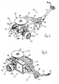
- Figure 1 is a front perspective view of a load transport assembly according to the invention;
- Figure 2 is a rear perspective view of the load transport assembly of Figure 1;
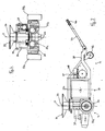
- Figure 3 is a side view of the load transport assembly of Figure 1;
- Figure 4 is a front view of the load transport assembly of Figure 1; and
- Figure 5 is a plan view of the load transport assembly of Figure 1, all of the Figures showing the load transport assembly with it's bodywork removed to show the internal components.
-
- Referring to the Figures, there is shown a load transport assembly 10 (herein after referred to as a tractor) having a body 12 comprising a
front region 14, arear region 16 and acentral region 18. - The
front region 14 of the body 12 includes aload transfer device 20, drive means in the form of twoelectric motors 22a and 22b, and a mainsupport wheel assembly 24. - The load transfer device is fully described in the Applicant's earlier UK patent application No. GB0307785.6 and European patent application No. EP03007688.9 and therefore will not be described in detail here. However it includes a
coupling 26 for receiving a hitch member of a vehicle trailer to be transported by the tractor 10, and lifting means in the form of a hydraulic ram (not shown) operable by means of ahydraulic system 28 to raise and lower thecoupling 26 on a principle axis X as shown in Figures 3 to 5. - The main
support wheel assembly 24 comprises anaxle 30 extending laterally of thefront region 14 of the body 12 with, rotatably mounted on each end, amain support wheel 32a and 32b respectively. Themain support wheel 32a is driven byelectric motor 22a whilst the main support wheel 32b is driven by electric motor 22b, and thus are controllable completely independently of each other. - The
central region 18 of the body 12 includes amain frame 34 surrounding abattery container 36 inside which are located batteries (not shown) which power the electric motors 22 and thehydraulic system 28. - The
rear region 16 of the body 12 includes alower frame portion 38 extending rearwardly and upwardly from a lower part of themain frame 34, and anupper frame portion 40 extending rearwardly and downwardly from an upper part of themain frame 34 to join thelower frame portion 38 part way along it's length at a point below which two ground engaging stabilisingwheels 42 are mounted for rotation around horizontal and vertical axes. Thelower frame portion 38 extends rearwardly beyond the two ground engaging stabilisingwheels 42, and at it's rearward end ahandle 44 is pivotally mounted on a horizontal axis. At its distal end thehandle 44 carries agrip portion 46 bearing controls (not shown) for control of theload transfer device 20 and the driving of the main support wheels 32. - The
rear region 16 also includes, located between the lower andupper frame portions pressurised air system 48 for connection to and operation of the air brakes of the vehicle trailer to be transported by the load transport assembly 10. - The tractor 10 is specifically adapted for transport of articulated lorry trailers of the kind having non-steering wheels at their rear end and a hitch and legs at their front end. When the trailers are connected to a lorry cab unit via the hitch the legs are folded up underneath the trailer, but when no lorry cab is connected to the trailer via the hitch the legs are down and the trailer stands on the legs at the front and the wheels at the rear.
- The tractor 10 is operated as follows. With all four
wheels 22, 42 on the ground the pedestrian operator uses the controls to drive it into position relative to the trailer to be transported, that is into a position with thecoupling 26 of theload transfer device 20 located directly beneath a hitch part of the trailer at the front end thereof. Theload transfer device 20 is then raised up, using the controls, underneath the hitch part until the weight of the front part of the trailer is taken off it's legs and onto theload transfer device 20. As theload transfer device 20 is located with it's principle axis X above the centre of theaxle 30 the load is thus transferred to the main support wheels 32 of the tractor 10. Because of the detailed construction of the tractor 10 the action of transferring the weight in this way may also lift the ground engaging stabilisingwheels 42 off the ground, such that only the main support wheels 32 are thus on the ground, although they may simply have the majority of the weight taken off them but remain in contact with the ground. - The trailer air brakes are connected to the
pressurised air system 48 such that they can be released to enable the trailer to be moved. - The pedestrian operator then operates the controls to drive the main support wheels 32 as necessary to move the trailer to it's next location. The control of the two electric motors 22 is entirely independent such that the wheels 32 can be driven at different speeds and in different directions simultaneously in order to steer the tractor 10 as required. Thus if the two main support wheels 32 are driven in opposite directions at the same speed the tractor rotates about the principle axis X of the load transfer device, but if they are driven in the same direction and at the same speed the tractor 10 moves in a straight line. Combinations, of speed and relative direction of drive of the wheels 32, in between these two extremes mean that the tractor 10 is very manoeuvrable thus enabling the trailers to be moved around crowded goods yards more easily than has previously been possible, and furthermore by a pedestrian operator rather than a qualified heavy goods vehicle driver.
- Once the trailer is in the desired location it's brakes are reapplied using the pressured
air system 48, which is then disconnected. Then the controls are used to operate theload transfer device 20 to lower thecoupling 26 and thus place the front of the trailer back onto it's legs. - It will be obvious that modifications may be made to the embodiment of tractor described above without departing from the scope of the invention. For example the pair of ground engaging stabilising
wheels 42 may be replaced with a single castor wheel. - In the present specification "comprises" means "includes or consists of" and "comprising" means "including or consisting of".
- The features disclosed in the foregoing description, or the following claims, or the accompanying drawings, expressed in their specific forms or in terms of a means for performing the disclosed function, or a method or process for attaining the disclosed result, as appropriate, may, separately, or in any combination of such features, be utilised for realising the invention in diverse forms thereof.
Claims (6)
- A load transport assembly (10) having:characterised in that the main support wheel assembly includes two drive wheels (32a, 32b) rotatably mounted on each end of an axle (30) which extends laterally of the body, and the drive means includes two drive motors (22a, 22b) one connected to each drive wheel such that each drive wheel is driveable independently of the other, and characterised in that the load transport device is located such that the generally vertical axis on which it moves passes through the centre of the axle.a) a body (12) with a front region (14), a rear region (16) and a central region (18);b) a pair of ground engaging stabilising wheels (42) mounted for rotation on the rear region of the body;c) a load transfer device (20), mounted on the front region of the body, including a coupling (26) which is moveable on a generally vertical axis (X) and which is adapted to engage with and bear the load;d) drive means (22a, 22b) mounted on the body;e) a main support wheel assembly (24) mounted on the front region of the body and driven by the drive means;f) control means which is operable to permit an operator to control the load transfer device and drive means;
- A load transport assembly according to claim 1 characterised in that the load transfer device is hydraulically operated.
- A load transport assembly according to claim 1 or 2 characterised in that it further includes batteries, mounted in the central region of the body, to power the drive means and load transfer device.
- A load transport assembly according to any one of the preceding claims characterised in that the drive wheels are larger than the ground engaging stabilising wheels.
- A load transport assembly according to any one of the preceding claims characterised in that the control means is constructed and arranged for use by a pedestrian operator.
- A load transport assembly according to any one of the preceding claims characterised in that it is specifically adapted to transport trailers having air brakes and further includes a pressurised air system (48) for coupling to and operation of the trailer air brakes.
Applications Claiming Priority (2)
| Application Number | Priority Date | Filing Date | Title |
|---|---|---|---|
| GB0318956A GB2404903B (en) | 2003-08-13 | 2003-08-13 | Load transport assembly |
| GB0318956 | 2003-08-13 |
Publications (2)
| Publication Number | Publication Date |
|---|---|
| EP1506902A2 true EP1506902A2 (en) | 2005-02-16 |
| EP1506902A3 EP1506902A3 (en) | 2006-04-12 |
Family
ID=28052398
Family Applications (1)
| Application Number | Title | Priority Date | Filing Date |
|---|---|---|---|
| EP04019075A Withdrawn EP1506902A3 (en) | 2003-08-13 | 2004-08-11 | Load transport assembly |
Country Status (2)
| Country | Link |
|---|---|
| EP (1) | EP1506902A3 (en) |
| GB (1) | GB2404903B (en) |
Cited By (8)
| Publication number | Priority date | Publication date | Assignee | Title |
|---|---|---|---|---|
| GB2407543A (en) * | 2003-10-11 | 2005-05-04 | Dalynn Designs Ltd | Pedestrian controlled vehicle for towing wheeled articles |
| EP1884439A2 (en) | 2006-07-28 | 2008-02-06 | Vire S.r.l. | Lift truck |
| WO2009043474A3 (en) * | 2007-09-28 | 2009-08-06 | Univ Stuttgart | Transporting device for load supporting elements, and method for controlling the same |
| ITRE20100024A1 (en) * | 2010-03-24 | 2011-09-25 | Acha S R L | SELF-PROPELLED TROLLEY FOR CHAIRS |
| EP2896516A1 (en) * | 2014-01-20 | 2015-07-22 | Krones AG | Device for transport of container treatment devices |
| WO2018172932A3 (en) * | 2017-03-20 | 2018-11-22 | Newell Gregory | Hitching cart mover |
| DE202017105316U1 (en) * | 2017-09-04 | 2018-12-06 | Krones Ag | Transport system and container handling system |
| WO2025170505A1 (en) * | 2024-02-09 | 2025-08-14 | Mika Innovation Ab | A drive unit for a trailer, vehicle combination comprising a drive unit and a trailer and a control system for controlling propulsion and steering of a drive unit |
Citations (2)
| Publication number | Priority date | Publication date | Assignee | Title |
|---|---|---|---|---|
| GB307785A (en) | 1928-03-13 | 1929-07-04 | Siemens Reiniger Veifa | Apparatus for operating rontgen tubes |
| GB2279934B (en) | 1993-07-17 | 1996-11-06 | Eurotech Int Ltd | A device for transporting a load |
Family Cites Families (9)
| Publication number | Priority date | Publication date | Assignee | Title |
|---|---|---|---|---|
| US2773612A (en) * | 1953-06-30 | 1956-12-11 | Lukens Steel Co | Apparatus for loading and unloading trailers and the like onto and from platforms and the like |
| DE3276479D1 (en) * | 1981-09-07 | 1987-07-09 | Craven Tasker Sheffield Ltd | Steerable device for moving trailer type vehicles |
| IT8321198U1 (en) * | 1983-03-21 | 1984-09-21 | Oldani Gaetano Omar | EQUIPPED SELF-PROPELLED TROLLEY FOR HANDLING HELICOPTERS BY TOWING |
| GB8510056D0 (en) * | 1985-04-19 | 1985-05-30 | Craven Tasker Sheffield Ltd | Steerable device |
| US5139102A (en) * | 1989-07-17 | 1992-08-18 | Dan Pocapalia | Trailer maneuvering dolly |
| DE9311075U1 (en) * | 1993-07-24 | 1994-11-24 | Strothmann, Rolf, Dr., 66123 Saarbrücken | Electric drive of a hand-drawn or pushed, mobile object |
| DE19723973A1 (en) * | 1996-06-08 | 1998-03-26 | Expresso Deutschland | Motorised trolley |
| DE19947426A1 (en) * | 1999-10-03 | 2001-04-05 | Expresso Deutschland Transp Ge | Transportable drive unit for transport trolley has manual steering device coupled to regulating and control unit for corresponding control of electric drive motors for driven wheels |
| GB2358844B (en) * | 2000-02-02 | 2003-04-16 | Peter Brian Missons | Powered caravan mover |
-
2003
- 2003-08-13 GB GB0318956A patent/GB2404903B/en not_active Expired - Fee Related
-
2004
- 2004-08-11 EP EP04019075A patent/EP1506902A3/en not_active Withdrawn
Patent Citations (2)
| Publication number | Priority date | Publication date | Assignee | Title |
|---|---|---|---|---|
| GB307785A (en) | 1928-03-13 | 1929-07-04 | Siemens Reiniger Veifa | Apparatus for operating rontgen tubes |
| GB2279934B (en) | 1993-07-17 | 1996-11-06 | Eurotech Int Ltd | A device for transporting a load |
Cited By (13)
| Publication number | Priority date | Publication date | Assignee | Title |
|---|---|---|---|---|
| GB2407543A (en) * | 2003-10-11 | 2005-05-04 | Dalynn Designs Ltd | Pedestrian controlled vehicle for towing wheeled articles |
| EP2399803A1 (en) * | 2006-07-28 | 2011-12-28 | Vire Automation S.r.l. | Lift truck |
| EP1884439A2 (en) | 2006-07-28 | 2008-02-06 | Vire S.r.l. | Lift truck |
| EP1884439A3 (en) * | 2006-07-28 | 2009-02-25 | Vire S.r.l. | Lift truck |
| EP2108564A1 (en) * | 2006-07-28 | 2009-10-14 | Vire S.r.l. | Lift truck |
| WO2009043474A3 (en) * | 2007-09-28 | 2009-08-06 | Univ Stuttgart | Transporting device for load supporting elements, and method for controlling the same |
| EP2772407A3 (en) * | 2007-09-28 | 2015-05-27 | Universität Stuttgart | Transport device for load holders and method for controlling the same |
| EP2371669A1 (en) * | 2010-03-24 | 2011-10-05 | Acha S.r.L. | Motorized cart for transporting chairs |
| ITRE20100024A1 (en) * | 2010-03-24 | 2011-09-25 | Acha S R L | SELF-PROPELLED TROLLEY FOR CHAIRS |
| EP2896516A1 (en) * | 2014-01-20 | 2015-07-22 | Krones AG | Device for transport of container treatment devices |
| WO2018172932A3 (en) * | 2017-03-20 | 2018-11-22 | Newell Gregory | Hitching cart mover |
| DE202017105316U1 (en) * | 2017-09-04 | 2018-12-06 | Krones Ag | Transport system and container handling system |
| WO2025170505A1 (en) * | 2024-02-09 | 2025-08-14 | Mika Innovation Ab | A drive unit for a trailer, vehicle combination comprising a drive unit and a trailer and a control system for controlling propulsion and steering of a drive unit |
Also Published As
| Publication number | Publication date |
|---|---|
| GB0318956D0 (en) | 2003-09-17 |
| GB2404903A (en) | 2005-02-16 |
| GB2404903B (en) | 2006-04-12 |
| EP1506902A3 (en) | 2006-04-12 |
Similar Documents
| Publication | Publication Date | Title |
|---|---|---|
| US4210217A (en) | Self-propelled steering device for trailers | |
| US4674942A (en) | Load hauling tandem combination | |
| US20040123768A1 (en) | Rail car mover apparatus for loader vehicle | |
| EP2184255A1 (en) | Self propelled lift trucks | |
| US7243747B2 (en) | Trailer provided with manoeuvring device | |
| US4576245A (en) | Self-propelled pedestrian-controlled tractor for towing helicopters | |
| US20220111915A1 (en) | Articulated Lorry Having a Tractor and a Trailer, Tractor, Trailer and Method for Axle Load Distribution in the Case of an Articulated Lorry | |
| US4117901A (en) | Self-propelled articulated vehicle | |
| CA2517750A1 (en) | Multi-function, all-terrain dolly for a snowmobile or the like | |
| EP1506902A2 (en) | Load transport assembly | |
| GB2342327A (en) | Powered vehicle mover | |
| WO2019123461A1 (en) | Steerable multi-terrain cart and method therefor | |
| US3779328A (en) | Trailer maneuvering mechanism | |
| CA2958442A1 (en) | Powered trailer moving device | |
| HK1076076A (en) | Load transport assembly | |
| US4838754A (en) | Method and apparatus for connecting a rear trailer in a tandem tractor-trailer assembly | |
| US20020139595A1 (en) | Selectively bypassing skid steering function | |
| US20030178814A1 (en) | Jack dolly | |
| CN210761043U (en) | Vehicle body structure with self-walking and traction functions | |
| GB2209718A (en) | Improvements in or relating to a trailer | |
| US4372571A (en) | Tractor and trailer combination | |
| GB2577813A (en) | Semi-trailer and electric drive module suitable for mounting on a semi-trailer | |
| WO2013044328A1 (en) | Steering system for trailers | |
| JPS6235654Y2 (en) | ||
| JPH07315257A (en) | Power carrier |
Legal Events
| Date | Code | Title | Description |
|---|---|---|---|
| PUAI | Public reference made under article 153(3) epc to a published international application that has entered the european phase |
Free format text: ORIGINAL CODE: 0009012 |
|
| AK | Designated contracting states |
Kind code of ref document: A2 Designated state(s): AT BE BG CH CY CZ DE DK EE ES FI FR GB GR HU IE IT LI LU MC NL PL PT RO SE SI SK TR |
|
| AX | Request for extension of the european patent |
Extension state: AL HR LT LV MK |
|
| REG | Reference to a national code |
Ref country code: HK Ref legal event code: DE Ref document number: 1076076 Country of ref document: HK |
|
| PUAL | Search report despatched |
Free format text: ORIGINAL CODE: 0009013 |
|
| AK | Designated contracting states |
Kind code of ref document: A3 Designated state(s): AT BE BG CH CY CZ DE DK EE ES FI FR GB GR HU IE IT LI LU MC NL PL PT RO SE SI SK TR |
|
| AX | Request for extension of the european patent |
Extension state: AL HR LT LV MK |
|
| 17P | Request for examination filed |
Effective date: 20061012 |
|
| AKX | Designation fees paid |
Designated state(s): AT BE BG CH CY CZ DE DK EE ES FI FR GB GR HU IE IT LI LU MC NL PL PT RO SE SI SK TR |
|
| 17Q | First examination report despatched |
Effective date: 20061122 |
|
| STAA | Information on the status of an ep patent application or granted ep patent |
Free format text: STATUS: THE APPLICATION IS DEEMED TO BE WITHDRAWN |
|
| 18D | Application deemed to be withdrawn |
Effective date: 20070403 |
|
| REG | Reference to a national code |
Ref country code: HK Ref legal event code: WD Ref document number: 1076076 Country of ref document: HK |