EP1506707A2 - Rear drag sound generating mechanism for a spinning reel - Google Patents
Rear drag sound generating mechanism for a spinning reel Download PDFInfo
- Publication number
- EP1506707A2 EP1506707A2 EP04254388A EP04254388A EP1506707A2 EP 1506707 A2 EP1506707 A2 EP 1506707A2 EP 04254388 A EP04254388 A EP 04254388A EP 04254388 A EP04254388 A EP 04254388A EP 1506707 A2 EP1506707 A2 EP 1506707A2
- Authority
- EP
- European Patent Office
- Prior art keywords
- knob
- rear drag
- mounting portion
- sounding
- recess
- Prior art date
- Legal status (The legal status is an assumption and is not a legal conclusion. Google has not performed a legal analysis and makes no representation as to the accuracy of the status listed.)
- Granted
Links
- 230000007246 mechanism Effects 0.000 title claims description 77
- 238000009987 spinning Methods 0.000 title claims description 48
- 230000002093 peripheral effect Effects 0.000 claims abstract description 40
- 230000004308 accommodation Effects 0.000 description 5
- 239000000463 material Substances 0.000 description 5
- 229920003002 synthetic resin Polymers 0.000 description 4
- 239000000057 synthetic resin Substances 0.000 description 4
- 230000006870 function Effects 0.000 description 3
- 230000000694 effects Effects 0.000 description 2
- 239000010410 layer Substances 0.000 description 2
- 230000000717 retained effect Effects 0.000 description 2
- 241000251468 Actinopterygii Species 0.000 description 1
- 229910000838 Al alloy Inorganic materials 0.000 description 1
- 229920000122 acrylonitrile butadiene styrene Polymers 0.000 description 1
- 229910052782 aluminium Inorganic materials 0.000 description 1
- XAGFODPZIPBFFR-UHFFFAOYSA-N aluminium Chemical compound [Al] XAGFODPZIPBFFR-UHFFFAOYSA-N 0.000 description 1
- 239000000428 dust Substances 0.000 description 1
- 229910052751 metal Inorganic materials 0.000 description 1
- 239000002184 metal Substances 0.000 description 1
- 238000000034 method Methods 0.000 description 1
- 238000012986 modification Methods 0.000 description 1
- 230000004048 modification Effects 0.000 description 1
- 238000007747 plating Methods 0.000 description 1
- 230000008569 process Effects 0.000 description 1
- 230000001105 regulatory effect Effects 0.000 description 1
- 230000035807 sensation Effects 0.000 description 1
- 239000002344 surface layer Substances 0.000 description 1
- 238000004804 winding Methods 0.000 description 1
Images





Classifications
-
- A—HUMAN NECESSITIES
- A01—AGRICULTURE; FORESTRY; ANIMAL HUSBANDRY; HUNTING; TRAPPING; FISHING
- A01K—ANIMAL HUSBANDRY; AVICULTURE; APICULTURE; PISCICULTURE; FISHING; REARING OR BREEDING ANIMALS, NOT OTHERWISE PROVIDED FOR; NEW BREEDS OF ANIMALS
- A01K89/00—Reels
- A01K89/02—Brake devices for reels
- A01K89/027—Brake devices for reels with pick-up, i.e. for reels with the guiding member rotating and the spool not rotating during normal retrieval of the line
- A01K89/028—Continuously applied
- A01K89/029—Continuously applied between spool shaft and frame
-
- A—HUMAN NECESSITIES
- A01—AGRICULTURE; FORESTRY; ANIMAL HUSBANDRY; HUNTING; TRAPPING; FISHING
- A01K—ANIMAL HUSBANDRY; AVICULTURE; APICULTURE; PISCICULTURE; FISHING; REARING OR BREEDING ANIMALS, NOT OTHERWISE PROVIDED FOR; NEW BREEDS OF ANIMALS
- A01K89/00—Reels
- A01K89/02—Brake devices for reels
- A01K89/027—Brake devices for reels with pick-up, i.e. for reels with the guiding member rotating and the spool not rotating during normal retrieval of the line
-
- A—HUMAN NECESSITIES
- A01—AGRICULTURE; FORESTRY; ANIMAL HUSBANDRY; HUNTING; TRAPPING; FISHING
- A01K—ANIMAL HUSBANDRY; AVICULTURE; APICULTURE; PISCICULTURE; FISHING; REARING OR BREEDING ANIMALS, NOT OTHERWISE PROVIDED FOR; NEW BREEDS OF ANIMALS
- A01K89/00—Reels
- A01K89/01—Reels with pick-up, i.e. with the guiding member rotating and the spool not rotating during normal retrieval of the line
-
- A—HUMAN NECESSITIES
- A01—AGRICULTURE; FORESTRY; ANIMAL HUSBANDRY; HUNTING; TRAPPING; FISHING
- A01K—ANIMAL HUSBANDRY; AVICULTURE; APICULTURE; PISCICULTURE; FISHING; REARING OR BREEDING ANIMALS, NOT OTHERWISE PROVIDED FOR; NEW BREEDS OF ANIMALS
- A01K89/00—Reels
- A01K89/01—Reels with pick-up, i.e. with the guiding member rotating and the spool not rotating during normal retrieval of the line
- A01K89/0114—Reciprocating mechanisms
Definitions
- the present invention generally relates to a rear drag operation structure. More specifically, the present invention relates to a rear drag operation structure that serves to operate a rear drag mechanism that is arranged on the rear of a reel unit of a spinning reel.
- a conventional rear drag operation structure includes a knob mounting portion, a first rear drag knob, and a second rear drag knob (see, for example, Japanese Utility Model Publication 3-5259. Figure 1).
- the knob mounting portion includes a tubular portion and a male threaded portion.
- the tubular portion has a tubular shape that projects rearward from the rear portion of the reel unit, and the male threaded portion is formed on an outer peripheral surface of the tubular portion.
- the first rear drag knob serves to finely adjust the drag force of the rear drag mechanism, and is mounted on the rear end portion of the knob mounting portion.
- the second rear drag knob includes a lever member and a nut member. The lever member is disposed between the rear portion of the reel unit and the front portion of the first rear drag knob.
- the nut member is mounted on the lever member so that the nut member is non-rotatable therewith but movable forward and backward relative thereto.
- the nut member is screwed onto the male threaded portion of the knob mounting portion.
- a rear drag operation structure for a spinning reel serves to operate a rear drag mechanism arranged on the rear of a reel unit, and includes a knob mounting portion, a first rear drag knob, and a second rear drag knob.
- the knob mounting portion includes a tubular portion and a male threaded portion.
- the tubular portion is adapted to be arranged on a rear of the reel unit so as to project rearward in a tubular shape from the rear portion of the reel unit.
- the male threaded portion is formed on an outer peripheral surface of the tubular portion.
- the first rear drag knob serves to adjust the drag force of the rear drag mechanism finely, and is mounted on the rear end portion of the knob mounting portion.
- the second rear drag knob serves to adjust the drag force of the rear drag mechanism, and includes a lever member and a nut member.
- the lever member is adapted to be disposed between the rear portion of the reel unit and the front portion of the first rear drag knob.
- the lever member can be brought into contact with the rear portion of the reel unit and the front portion of the first rear drag knob.
- the nut member is mounted on the lever member so that the nut member is non-rotatable relative thereto but movable forward and backward relative thereto.
- the nut member is screwed onto the male threaded portion of the knob mounting portion.
- the drag force of the rear drag mechanism can be adjusted by moving the nut member that is screwed onto the knob mounting portion forward and backward relative to the lever member and the knob mounting portion by pivoting the second rear drag knob.
- the design of the silhouette of the rear drag operational structure can be improved.
- a rear drag operation structure for a spinning reel is the rear drag operation structure for a spinning reel disclosed in the first aspect of the present invention, in which the nut member has at least one first recess that is formed on an outer periphery of a rear end portion of the nut member so as to extend frontward, and the lever member includes a tubular lever part and a first projection that is formed on an inner periphery of the tubular lever part so as to engage with the first recess.
- the lever member can be easily positioned on the rear portion of the nut member because the first projections formed on the inner periphery of the tubular lever part of the lever member can engage with the first recess formed in the outer periphery of the nut member.
- the first projection of the lever member will mesh with the first recess of the nut member, and the nut member will rotate together with the lever member.
- the first recess of the nut member will slide forward and backward on the first projection of the lever member, and the nut member will move forward and backward relative to the lever member and the knob mounting portion.
- the drag force of the rear drag mechanism can be adjusted by moving the nut member forward and backward relative to the lever member and the knob mounting portion. In this way, there will no longer be any need to provide gaps between the second rear drag knob and the rear portion of the reel unit and between the second rear drag knob and the front portion of the first rear drag knob to give a room for the lever member to move. Thus, it is difficult for foreign matter to enter inside the reel unit. Then, the design of the silhouette of the rear drag operational structure can be improved.
- a rear drag operation structure for a spinning reel is the rear drag operation structure for a spinning reel disclosed in the first or second aspect , in which the nut member has at least one second recess that is formed on an outer periphery of a front end portion of the nut member so as to extend rearward, and the lever member includes a tubular lever part and a second projection that is formed on an inner periphery of the tubular lever part so as to engage with the second recess.
- the lever member can be easily positioned on the front portion of the nut member because the second recess formed on the inner periphery of the tubular portion of the lever member can engage with the second projection formed in the outer periphery of the nut member.
- the second recess of the lever member will mesh with the second projection of the nut member, and the nut member will rotate together with the lever member.
- the second projection of the nut member will slide forward and backward on the second recess of the lever member, and the nut member will move forward and backward relative to the lever member and the knob mounting portion.
- the drag force of the rear drag mechanism can be adjusted by moving the nut member forward and backward relative to the lever member and the knob mounting portion. In this way, there will no longer be any need to provide gaps between the second rear drag knob and the rear portion of the reel unit and between the second rear drag knob and the front portion of the first rear drag knob to give a room for the lever member to move. Thus, it is made difficult for foreign matter to enter inside the reel unit. Then, the design of the silhouette of the rear drag operational structure can be improved.
- a rear drag operation structure for a spinning reel is the rear drag operation structure for a spinning reel disclosed in any of the first to third aspects, in which the first rear drag knob is mounted on the knob mounting portion so that the first rear drag knob is rotatable but not movable forward and backward relative to the knob mounting portion.
- the second rear drag knob is adapted to be disposed such that the second rear drag knob substantially contacts the rear portion of the reel unit and the first rear drag knob.
- the first rear drag knob even if the first rear drag knob is rotated, the first rear drag knob will not move forward and backward relative to the knob mounting portion because the first rear drag knob is mounted on the knob mounting portion to be rotatable but not movable forward and backward therewith.
- the gap between the rear portion of the second rear drag knob and the front portion of the first rear drag knob can be prevented from increasing in size.
- the front portion of the second rear drag knob and the rear portion of the reel unit and the rear portion of the second rear drag knob and the front portion of the first rear drag knob substantially contact one another, there are still micro clearances therebetween. Accordingly, an initial dynamic load when the second rear drag knob is pivoted can be reduced. The smaller the gaps become, the more difficult it can be made for foreign matter to enter into the reel unit. Then, the design of the silhouette of the rear drag operational structure can be improved.
- a rear drag operation structure for a spinning reel is the rear drag operation structure for a spinning reel disclosed in any of the first to fourth aspects, further including a sound generating mechanism that generates sound when the second rear drag knob is pivoted in a predetermined pivot range and is arranged between the second rear drag knob and the knob mounting portion.
- the sound generating mechanism includes a plurality of sounding recesses, a mounting recess, a sounding pin, and an urging member.
- the plurality of sounding recesses are formed circumferentially spaced apart in the inner periphery of the second rear drag knob in accordance with the pivot range.
- the mounting recess is formed in the outer periphery of the knob mounting portion in a position opposite the sounding recess.
- the sounding pin is mounted in the mounting recess such the sounding pin engages with the sounding recesses.
- the urging member is disposed in the mounting recess and urges the sounding pin toward the sounding recesses.
- a rear drag operation structure for a spinning reel is the rear drag operation structure for a spinning reel disclosed in any of the first to fifth aspects, wherein the knob mounting portion has a female threaded portion formed on an inner peripheral surface of the tubular portion, and the first rear drag knob includes a pressure member that engages the female threaded portion of the knob mounting portion, such that the pressure member is rotatable and movable forward and backward relative to the knob mounting portion.
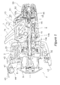
- Figure 1 is a cross sectional view of a spinning reel according to one embodiment of the present invention.
- Figure 2 is an enlarged cross sectional view of the rear portion of the spinning reel according to the embodiment of the present invention.
- Figure 3 is an enlarged cross sectional view of a first rear drag knob of the spinning reel according to the embodiment of the present invention.
- Figure 4 is an exploded perspective view of a retaining structure of the spinning reel according to the embodiment of the present invention.
- Figure 5 is an enlarged cross sectional view of a second rear drag knob of the spinning reel according to the embodiment of the present invention.
- Figure 6 is an enlarged cross sectional view of a first rear drag sound generating mechanism installed on the spinning reel according to the embodiment of the present invention
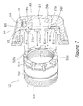
- Figure 7 is a schematic view of a knob mounting portion of the spinning reel and a cross sectional view of a first rear drag knob according to the embodiment of the present invention
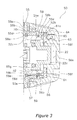
- Figure 8 is a cross sectional view of a second rear drag sound generating mechanism installed in the spinning reel according to the embodiment of the present invention, viewed along line VIII-VIII of Fig. 1;
- Figure 9 is an enlarged cross sectional view of the second rear drag sound generating mechanism according to the embodiment of the present invention.
- Figure 10 is an enlarged cross sectional view of a second rear drag knob of a spinning reel according to another embodiment of the present invention.
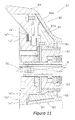
- Figure 11 is an enlarged cross sectional view of a second rear drag knob of the spinning reel according to still another embodiment of the present invention.
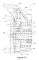
- Figure 12 is an enlarged cross sectional view of a second rear drag knob of the spinning reel according to still another embodiment of the present invention.
- Fig. 1 shows a spinning reel according to an embodiment of the present invention.
- the spinning reel primarily includes a reel unit 1 that rotatively supports a handle 10, a rotor 2, a spool 3, a first rear drag knob 50, and a second rear drag knob 51.
- the reel unit 1 includes a reel body 1a, and a rod attachment leg 1b that extends diagonally upward and forward from the reel body 1a.
- An accommodation space is formed in the interior of the reel body 1a.
- a rotor drive mechanism 5 that rotates the rotor 2 in conjunction with the rotation of the handle 10, and an oscillating mechanism 6 that moves the spool 3 back and forth to uniformly wind fishing line, are arranged in the accommodation space.
- a knob mounting portion 52 that includes a tubular portion 52g that projects rearward from a rear portion 1c of the reel body 1a is arranged on the rear portion 1c.
- a plurality of first engagement recesses 52b are formed spaced apart by a predetermined distance in the circumferential direction on the rear end surface of the tubular portion 52g of the knob mounting portion 52.
- a first female threaded portion 52a is formed on a rear inner peripheral surface of the tubular portion 52g of the knob mounting portion 52
- a third male threaded portion (male threaded portion) 52e is formed on the outer peripheral surface of the tubular portion 52g of the knob mounting portion 52.
- annular first annular groove 52c and an annular second annular groove 52d are formed in a predetermined spaced relationship in the rear portion of the third male threaded portion 52e.
- second engagement recesses 52f are formed in the rear end of the knob mounting portion 52 extending axially through the second annular groove 52d.
- the second engagement recesses 52f are formed in a predetermined spaced relationship in the circumferential direction, and the depths thereof are deeper than the depth of the second annular groove 52d.
- a positioning recess 96 is arranged adjacent to the third male threaded portion 52e of the knob mounting member 52 in order to position the second rear drag knob 51. Both side surfaces of the positioning recess 96 in the rotational direction are formed in a fan-shaped taper from the circumferential the bottom portion of the positioning recess 96 to the opening thereof.
- a second mounting recess 72 is arranged in front of the third male threaded portion 52e of the knob mounting portion 52 in order to mount a second sounding pin 73 and a second coil spring 74 described below.
- the rotor 2 is rotatively supported on the front of the reel unit 1.
- the rotor 2 includes a rotor cylindrical portion 30, a first rotor arm 31 and a second rotor arm 32.
- the first and second rotor arms 31, 32 are arranged on mutually opposing positions of the rotor cylindrical portion 30.
- the rotor cylindrical portion 30 and the first and second rotor arms 31, 32 are, for example, made of an aluminum alloy, and are formed to be integral with the rotor cylindrical portion 30.
- the first and second rotor arms 31, 32 are connected to the circumferential surface of the rotor cylindrical portion 30 such that the bases of the first and second rotor arms 31, 32 extend in the circumferential direction on the circumferential surface of the rotor cylindrical portion 30.
- the first and second rotor arms 31, 32 project outward from the rotor cylindrical portion 30 and then curve and extend forward.
- a first bail support member 40 is pivotably mounted to the tip of the first rotor arm 31.
- a line roller 41 for guiding fishing line to the spool 3 is mounted to the front end of the first bail support member 40.
- a second bail support member 42 is pivotably mounted to the front end of the second rotor arm 32.
- a bail 43 that is a wire member curved into an approximate U-shape is fixedly held between the line roller 41 and the second bail support member 42.
- the first bail support member 40, the second bail support member 42, the line roller 41, and the bail 43 form a bail arm 44 that guides the fishing line onto the spool 3.
- the bail arm 44 can pivot between a line-guiding posture shown in Fig. 1 and a line-releasing posture which flips from the line-guiding posture.
- the rotor drive mechanism 5 includes a face gear 11 and a pinion gear 12.
- the face gear 11 rotates together with a handle shaft 10a that is connected to the handle 10, and the pinion gear 12 meshes with the face gear 11.
- the pinion gear 12 is formed in a tubular shape, and a central portion and a rear end portion thereof in the axial direction are rotatively supported on the reel body 1a via bearings 14a and 14b.
- a front portion of the pinion gear 12 passes through the center portion of the rotor 2 and extends toward the spool 3.
- a spool shaft 14 passes through the inner peripheral portion of the pinion gear 12, and slidably moves forward and backward along the rotational axis of the pinion gear 12.
- the spool 3 winds fishing line around the outer peripheral surface thereof, and as shown in Fig. 1, is mounted on the front portion of the rotor 2 so that the spool 3 can be shifted back and forth.
- the spool 3 is composed of a spool unit 7, a brim 8, and a brim fixing member 9.
- the spool unit 7 includes a bobbin 4a and a skirt portion 4b.
- the bobbin 4a is formed into a tubular shape and fishing line is wound around the outer periphery thereof.
- the skirt portion 4b is formed such that the diameter thereof is larger than the outer diameter of the bobbin 4a, and is formed to be integral with the rear portion of the bobbin portion 4a.
- the brim 8 is mounted on the front portion of the bobbin portion 4a, and is fixed to the spool unit 7 by the bobbin fixing member 9.
- the oscillating mechanism 6 is a device that causes the spool shaft 14 connected to the spool 3 to move forward and backward, and cause the spool 3 to move in the same direction.
- the oscillating mechanism 6 includes a worm 15 disposed below and parallel to the spool shaft 14, a slider 16 that moves back and forth along the worm 15, a guide shaft (not shown in the figures) that is disposed parallel to the spool shaft 14, and an intermediate gear (not shown in the figures) that is fixedly coupled to the front end of the worm 15.
- the slider 16 is non-rotatably mounted to the spool shaft 14.
- the rear drag mechanism 45 is a mechanism that causes a drag force to be applied to the spool 3. As shown in Fig. 2, the rear drag mechanism 45 is composed of a cylindrical first bush 18, first and second friction engagement portions 19, 20 that include a plurality of friction plates 19a, 20a, a coil spring 21 for pressing the first friction plates 19a of the first friction engagement portion 19 and a first pressure member 22 for urging the friction plates 19a of the first friction engagement portion 19, and a second pressure member 25 for urging the friction plates 20a of the second friction engagement portion 20.
- the first bush 18 is formed in a tubular shape in which the outer peripheral surface thereof has mutually parallel chamfered portions.
- a second bush 18a is non-rotatably and non-slidably fitted into the front portion of the inner periphery of the first bush 18.
- the second bush 18a is also formed in a tubular shape in which the outer peripheral surface thereof has mutually parallel chamfered portions.
- the second bush 18a is, for example, made of a synthetic resin that is highly slidable, and the spool shaft 14 is non-rotatably and slidably fitted into the inner periphery thereof.
- a flange portion 23 is arranged on the outer peripheral surface of the rear portion of the first bush 18.
- the friction plates 19a of the first friction engagement portion 19 are disposed to the front and rear of the flange portion 23.
- the coil spring 21 is disposed on the rear portion of the first friction engagement portion 19.
- the first pressure member 22 is connected in series with the rear portion of the coil spring 21.
- a front portion 22a of the first pressure member 22 is formed into a cylindrical shape, and a first male threaded portion 22b is arranged on the outer peripheral surface thereof.
- a rear portion 22c of the first pressure member 22 is formed into a closed-end tubular shape having a diameter that is smaller than the front portion 22a of the first pressure member 22, and the outer peripheral surface of the rear portion 22c has two chamfered portions that are parallel to each other.
- a plate member 20b non-rotatably mounted on the outer periphery of the first bush 18 is interposed by the friction plates 20a of the second friction engagement portion 20.
- Projections 20c that engage with a sounding spring 81 (described below) are formed on the outer peripheral surface of the plate member 20b so as to be spaced apart by a predetermined distance in the circumferential direction.
- a second pressure member 25 is disposed on the rear portion of the second friction engagement portion 20, and engages with an engagement portion 25b of the second rear drag knob 51 (described below).
- the first male threaded portion 22b of the first pressure member 22 is rotatively mounted on the first female threaded portion 52a formed in the inner peripheral surface of the knob mounting member 52.
- the first pressure member 22 can rotate in the interior of the knob mounting portion 52 while moving forward and backward, and compresses and decompresses the coil spring 21.
- the second pressure member 25 is rotatively mounted on the outer periphery of the first bush 18. When the second pressure member 25 rotates and presses on the friction plates 20a of the second friction engagement portion 20, both surfaces of the plate member 20b are pressed by the friction plate 20a.
- the first rear drag knob 50 serves to finely adjust the drag force of the rear drag mechanism 45, and as shown in Figs. 3 and 4, includes a first knob member 55, a second knob member 56, and a ring member 57.
- the first knob member 55 is, for example, made of a synthetic resin, and is formed into a tubular shape.
- the first knob member 55 includes a first tubular portion 55a, a second tubular portion 55b, and a third tubular portion 55c, and the first to third tubular portions 55a, 55b, 55c are formed integrally with each other.
- An annular third annular groove 55d is arranged in the front portion of the inner peripheral surface of the first tubular portion 55a.
- a first engagement member 58a is fitted in the third engagement groove 55d and the first annular groove 52c of the knob mounting portion 52.
- an O-ring is employed as the first engagement member 58a.
- the second tubular portion 55b is integrally formed with the rear end of the first tubular portion 55a, and the outer diameter of the second tubular portion 55b is smaller than the outer diameter of the first tubular portion 55a.
- the third tubular portion 55c is integrally formed with the rear end of the second tubular portion 55b, and the outer diameter of the third tubular portion 55c is smaller than the outer diameter of the second tubular portion 55b.
- a second male threaded portion 55e is arranged on the outer peripheral surface of the third tubular portion 55c.
- a retaining engagement surface 55g is arranged on the rear end of the third tubular portion 55c.
- the retaining engagement surface 55g is formed in a planar shape that is substantially perpendicular to the rotational axis.
- a washer 59 is disposed on the rear end of the retaining engagement surface 55g.
- the washer 59 includes a circular portion 59a and projections 59b.
- the circular portion 59a is in contact with the retaining engagement surface 55g.
- the projections 59b are formed so that they project inward from the inner peripheral surface of the circular portion 59a and can engage with the plurality of second engagement recesses 52f.
- the washer 59 is positioned by a second engagement member 58b.
- the second engagement member 58b is brought into contact with the rear surface of the washer 59 while being inserted into the second annular groove 52d formed in the knob mounting portion 52.
- a C-shaped retaining ring is employed as the second engagement member 58b, and the outer diameter is larger than the inner diameter of the circular portion 59a of the washer 59.
- the second knob member 56 is, for example, made of a synthetic resin, and is formed into a closed-end tubular shape.
- First and second engagement portions 56e, 56f are provided on the closed end portion of the second knob member 56.
- the first engagement portion 56e is an oval-shaped hole formed in the central bottom portion thereof.
- the rear portion 22c of the first pressure member 22 is chamfered in parallel on the outer peripheral surface thereof and is engaged with the first engagement portion 56e.
- the rear portion 22c of the first pressure member 22 is non-rotatable in the first engagement portion 56e and can slide forward and backward therein.
- the second engagement portion 56f is formed in a toroidal recessed shape in the outer periphery of the closed end portion of the second knob member 56.
- a sounding member 61 (described below) is engaged with the second engagement portion 56f.
- a first mounting recess 63 is formed in the bottom portion of the second engagement portion 56f that is formed in a toroidal recessed shape, and a first sounding pin 64 and a first coil spring 65 (described below) are disposed in the first mounting recess 63.
- An annular fourth annular groove 56b and a second female threaded portion 56d are arranged on the inner peripheral surface of the second knob member 56.
- the fourth annular groove 56b is formed on the closed end side of the second knob member 56, and has a diameter that is larger than the outer diameter of the sounding mechanism 61 described below.
- the second female threaded portion 56d is formed on the open side of the second knob member 56.
- the second knob member 56 is connected to the first knob member 55 by screwing the second female threaded portion 56d together with the second male threaded portion 55e of the first knob member 55. When this occurs, the ring member 57 will be disposed between the first knob member 55 and the second knob member 56.
- the ring member 57 is, for example, made of aluminum. Note that the design of the first rear drag knob 50 can be improved by installing the ring member 57 between the first knob member 55 and the second knob member 56.
- the second rear drag knob 51 serves to adjust the drag force of the rear drag mechanism 45 more quickly than the first rear drag knob 50 does, and is disposed between the rear portion 1c of the reel body 1a and the front portion of the first rear drag knob 50.
- the second rear drag knob 51 includes a first lever member (lever member) 90, a second lever member (lever member) 91, a positioning pin 92 and a fourth coil spring 93, a fixing member (lever member) 94, and a tubular member (nut member) 95.
- the first lever member 90 is formed in a tubular shape, and includes a first lever portion 90a that projects radially outward from the outer peripheral surface of the first lever portion 90a.
- the first lever portion 90a includes an accommodation portion that opens in the forward direction, and a second lever portion 91a (described below) can be accommodated in this accommodation portion.
- first engagement projections (first projections) 90b are formed in a predetermined spaced relationship in the circumferential direction on the first lever member 90 and project toward the inner peripheral portion thereof.
- a minute gap is provided between the rear portion of the first lever member 90 and the front portion of the first rear drag knob 50. Then, when the second rear drag knob 51 is pivoted, the rear portion of the first lever member 90 can come into contact with the front portion of the first rear drag knob 50.
- the second lever member 91 is formed into a tubular shape, and is disposed on the inner peripheral side of the first lever member 90.
- the second lever member 91 includes a second lever portion 91a that is formed to project radially outward, and by accommodating the second lever portion 91a in the accommodation portion of the first lever portion 90a, the second lever member 91 will not rotate with respect to the first lever member 90.
- second engagement recesses (second recesses) 91c are formed in a predetermined spaced relationship in the circumferential direction on the inner peripheral surface of the second lever member 91.
- a fourth mounting recess 91b is formed in the second lever portion 91a, and the fourth mounting recess 91b is disposed such that the opening therein is facing the forward direction.
- a positioning pin 92 and a fourth coil spring 93 are mounted in the fourth mounting recess 91b.
- the positioning pin 92 includes a fourth head portion 92a, a fourth mounting portion 92b, and a fourth shaft portion 92c.
- the fourth head portion 92a and the fourth mounting portion 92b are integrally formed into a shape that resembles an upside down L.
- the fourth head portion 92a is formed to point in the rotation shaft direction (downward as viewed in Fig.5), and the fourth mounting portion 92b is formed to point horizontally (approximately parallel to the rotation shaft).
- the fourth head portion 92a is formed into a rectangular column shape, and both side surfaces of the tip portion thereof are tapered.
- the front end of the fourth mounting portion 92b is engaged with the bottom side surface (right hand side surface as viewed in Fig.5) of the fourth mounting recess 91b.
- the fourth shaft portion 92c is a shaft shaped portion that is connected to the fourth mounting portion 92b, and the fourth coil spring 93 can be disposed around the outer periphery thereof.
- the base end of the fourth coil spring 93 is brought into contact with the side surface (upper side as viewed in Fig.5) of the fourth mounting recess 91b, and the tip end (bottom end as viewed in Fig. 5) is brought into contact with a step portion between the fourth mounting portion 92b and the fourth shaft portion 92c.
- the fourth coil spring 93 is stored in the fourth mounting recess 91b in the compressed state, and urges the positioning pin 92 toward the positioning recess 96.
- the positioning pin 92 and the fourth coil spring 93 are disposed in the fourth mounting recess 91b, when the second rear drag knob 51 is pivoted, the positioning pin 92 will arrive at a position opposite the positioning recess 96 formed in the upper portion of the knob mounting member 52, and the head portion 92a of the positioning pin 92 will engage with the positioning recess 96.
- the fixing member 94 serves to prevent the positioning pin 92 and the fourth coil spring 93 from falling out from the fourth mounting recess 91b, and is, for example, fixed to the lever member 91 with a bolt. This allows the second rear drag knob 51 to be assembled sequentially starting with a member positioned in front and working its way rearward. In addition, a minute gap is provided between the front portion of the fixing member 94 and the rear portion 1c of the reel body 1a. Then, when the second rear drag knob 51 is pivoted, the front portion of the fixing member 94 can come into contact with the rear portion 1c of the reel body 1a.
- the outer diameter of the front portion of the tubular member 95 is formed to be larger than the outer diameter of the central portion thereof, and a step portion between the front portion and the central portion is formed into a taper shape.
- Second engagement projections (second projections) 95a are formed from the front end rearward on the front outer peripheral surface of the tubular member 95, and a plurality of these second engagement projections 95a are disposed circumferentially spaced apart on the tubular member 95.
- An engagement portion 95b that serves to transmit the movement of the second rear drag knob 51 to the second pressure member 25 is formed on the front inner peripheral edge of the tubular member 95.
- first engagement recesses (first recesses) 95c are formed from the rear end forward on the rear outer peripheral surface of the tubular member 95, and a plurality of these first engagement recesses 95c are disposed circumferentially spaced apart on the tubular member 95.
- the second engagement projections 95a of the tubular member 95 are engaged with the second engagement recesses 91c of the second lever member 91, and the first engagement recesses 95c are engaged with the first engagement projections 90b of the first lever member 90.
- the stepped portion and the central portion of the tubular member 95 will be in contact with the inner peripheral surface of the second lever member 91.
- the tubular member 95 will be mounted such that it is not relatively rotatable but relatively movable forward and backward with respect to the first and second lever members 90, 91.
- a third female threaded portion 95e is arranged on the inner peripheral surface of the tubular member 95, and by screwing the third female threaded portion 95e onto the third male threaded portion 52e of the knob mounting portion 52, the tubular member 95 will be rotatively mounted to the knob mounting portion 52.
- the material employed for the first lever member 90 and the fixing member 94 is different from the material employed for the second lever member 91.
- the first lever member 90 and the fixing member 94 are made from ABS resin
- the second lever member 91 is made from a synthetic resin.
- a metal plate layer 99 is plated onto the surface layer side of the first lever member 90 and the fixing member 94.
- the rear drag sound generating mechanism includes a first rear drag sound generating mechanism 60 (a sound generating mechanism used when the first rear drag knob is operated), a second rear drag sound generating mechanism 70 (a sound generating mechanism used when the second rear drag knob is operated), and a third rear drag sound producing mechanism 80 (a sound producing mechanism used when the drag is operated).
- the rear drag sound generating mechanism 60 is disposed between the knob mounting portion 52 and the second knob member 56, and generates sound by the relative rotation of the knob mounting portion 52 and the first rear drag knob 50.
- the first rear drag sound generating mechanism 60 includes a sounding member 61, a retaining member 62, a first mounting recess 63, a first sounding pin 64, and a first coil spring 65.
- the sounding member 61 includes a disk portion 61a that is formed into a ring shape, a plurality of sounding recesses 61b that are disposed spaced apart in the rotational direction in one surface of the disk portion 61a, and engagement portions 61c that are integrally formed with another surface of the disk portion 61a.
- the disk portion 61a of the sounding member 61 is engaged with the second engagement portion 56f of the second knob member 56, and can rotate with respect to the second knob member 56.
- the outer diameter of the disk portion 61a is formed to be smaller than the inner diameter of the fourth annular groove 56b.
- the engagement portion 61c is formed to project toward the first engagement recesses 52b formed in the rear end surface of the knob mounting portion 52, and engages with the first engagement recesses 52b.
- the retaining member 62 is arranged in order to prevent the sounding member 61 from falling out.
- the retaining member 62 is, for example, a C-shaped retaining ring, and is disposed in the fourth annular groove 56b.
- the inner diameter of the retaining member 62 is formed to be smaller than the outer diameter of the disk portion 61a of the sounding member 61.
- the first mounting recess 63 is formed in the closed end of the second knob member 56, in a position opposite the plurality of first sounding recesses 61b.
- the first sounding pin 64 is mounted in the first mounting recess 63 so as to be able to move forward and backward, and engages with the first sounding recesses 61b of the sounding member 61.
- the first sounding pin 64 includes a first head portion 64a, a first mounting portion 64b that is connected to the first head portion 64a, and a first shaft portion 64c that is connected to the first mounting portion 64b.
- the first head portion 64a is formed such that the front end thereof is a smooth convex shape. The front end of the front head portion 64a generates a clicking sound by repeatedly striking the first sounding recesses 61b.
- the front end of the first head portion 64a of the first sounding pin 64 is formed in a smooth convex shape, and thus the first sounding pin 64 generates clicking sounds with little resistance.
- the first mounting portion 64b is formed to have a diameter that is larger than that of the first head portion 64a and smaller than the inner diameter of the first mounting recesses 63.
- the first shaft portion 64c is a shaft shaped component that is formed to have a diameter that is smaller than that of the first mounting portion 64b, and the first coil spring 65 can be disposed around the outer periphery of the first shaft portion 64c.
- the front end of the first coil spring 65 can be brought into contact with the step portion between the first mounting portion 64b and the first shaft portion 64c.
- the first coil spring 65 is disposed on the outer periphery of the first shaft portion 64c of the first sounding pin 64. Accordingly, the base end of the first coil spring 65 is brought into contact with the bottom portion of the first mounting recess 63, and the front end of the first coil spring 65 is brought into contact with the step portion between the first mounting portion 64b and the first shaft portion 64c.
- the first coil spring 65 is accommodated in the first mounting recess 63 in the compressed state, and urges the first sounding pin 64 toward the first sounding recesses 61b.
- the second rear drag sound generating mechanism 70 is disposed between the knob mounting portion 52 and the second lever member 91 that is non-rotatively accommodated in the first lever member 90, and generates sound by pivoting of the second rear drag knob 51.
- the second rear drag sound generating mechanism 70 includes second sounding recesses 71, a second mounting recess 72, a second sounding pin 73, and a second coil spring 74.
- the second sounding recesses 71 are formed into groove shapes that extend in the axial direction, and are formed spaced apart in the circumferential direction in the inner peripheral side surface in the forward direction of the second lever member 91 in accordance with the pivot range thereof.
- the second mounting recess 72 is formed in the outer peripheral side surface of the knob mounting portion 52 such that it is opposite the second sounding recesses 71.
- An engagement hole 72a is formed in the bottom portion of the second mounting recess 72.
- the second sounding pin 73 is mounted in the second mounting recess 72 so as to be able to move in and out therefrom, and engages with the second sounding recesses 71.
- the second sounding pin 73 includes a second head portion 73a, a second mounting portion 73b that is connected to the second head portion 73a, and a second shaft portion 73c that is connected to the second mounting portion 73b.
- the second head portion 73a is formed such that the front end thereof is a smooth convex shape. The front end of the second head portion 73a generates a clicking sound by repeatedly striking the second sounding recesses 71.
- the front end of the second head portion 73a of the second sounding pin 73 is formed in a smooth convex shape, and thus the second sounding pin 73 generates clicking sounds with little resistance.
- the second mounting portion 73b is formed to have a diameter that is larger than that of the second head portion 73a and smaller than the inner diameter of the second mounting recess 72.
- the second shaft portion 73c is a shaft shaped component that is formed to have a diameter that is smaller than that of the second mounting portion 73b, and the second coil spring 74 can be disposed around the outer periphery of the second shaft portion 73c.
- the second shaft portion 73c is slidably engaged in the axial direction in the engagement hole 72a formed in the second mounting recess 72.
- the second coil spring 74 is disposed on the outer periphery of the second shaft portion 73c of the second sounding pin 73. Accordingly, the base end of the second coil spring 74 is brought into contact with the bottom portion of the second mounting recess 72, and the front end of the second coil spring 74 is brought into contact with the step portion between the second mounting portion 73b and the second shaft portion 73c.
- the second coil spring 74 is accommodated in the second mounting recess 72 in the compressed state, and urges the second sounding pin 73 toward the second sounding recesses 71.
- the third rear drag sound generating mechanism 80 generates sound when the rear drag mechanism 45 is operated.
- the third rear drag sound generating mechanism 80 includes a sounding spring 81, and projections 20c that are formed on the outer peripheral surface of the plate member 20b.
- the sounding spring 81 is, for example, a plate spring that is formed into an approximate L shape, and is fixedly held at one end thereof to the reel body 1a. The other end of the sounding spring 81 engages with the projection 20c. In this way, when the rear drag mechanism 45 is operated, the spool shaft 14 and the first bush 18 rotate together with the plate member 20b, and the projections 20c of the plate member 20b repeatedly strike the other end of the sounding spring 81 and generate sound.
- the bail 43 When the spinning reel described above is to be used, the bail 43 will be pushed over to the line releasing side when the fishing line is to be reeled out. Then, when the fishing rod is cast, fishing line is reeled out from the spool 3. When the fishing line is to be retrieved, the bail 43 is returned to the line retrieving side.
- the handle 10 When the handle 10 is rotated in the line winding direction in this state, the rotational force is transmitted to the pinion gear 12 via the handle shaft 10 and the face gear 11.
- the rotational force transmitted to the pinion gear 12 rotates the rotor 2 on the front portion of the pinion gear 12.
- the rotational force transmitted to the pinion gear 12 simultaneously rotates the worm 15 via the intermediate gear (not shown in the figures) that is meshed with the pinion gear 12.
- the slider 16 that meshes with the spiral grooves of the worm 15 is guided by the guide shaft (not shown in the figures) and moves forward and backward.
- the spool shaft 14 and the spool 3 reciprocate forward and backward together with the slider 16.
- Fishing line that is guided from the bail 43 and the line roller 41 is uniformly wound around the outer periphery of the spool 3 forward and backward due to the rotation of the rotor 2 and the forward and backward movement of the spool 3.
- the first rear drag sound generating mechanism 60 in the second knob member 56 of the first rear drag knob 50, it will be necessary to mount the first rear drag sound generating mechanism 60 in the second knob member 56 of the first rear drag knob 50.
- the first sounding pin 64 and the first coil spring 65 are disposed in the first mounting recess 63 of the second knob member 56.
- the sounding member 61 is mounted on the second engagement portion 56f of the second knob member 56 such that the first head portion 64a of the first sounding pin 64 is in contact with a first sounding recess 61b of the sounding member 61.
- the retaining member 62 is mounted on the fourth annular groove 56b formed in the second knob member 56 to retain the sounding member 61.
- the ring member 57 is first disposed on the first knob member 55 in order to mount the first rear drag knob 50 on the knob mounting portion 52. Then, the third annular groove 55d of the first knob member 55 is engaged with the first engagement member 58a disposed in the first annular groove 52c of the knob mounting portion 52. Next, the washer 59 is disposed in the rear portion of the third tubular portion 55c of the first knob member 55.
- the projections 59b of the washer 59 engage with the second engagement recesses 52f from the rear end of the knob mounting portion 52, and the front surface of the circular portion 59a of the washer 59 is brought into contact with the retaining engagement surface 55g of the first knob member 55.
- the projections 59b of the washer 59 are engaged in the second engagement recesses 52f of the knob mounting portion 52, and thus the rotation of the washer 59 is restricted with respect to the knob mounting portion 52.
- the second engagement member 58b is brought into contact with the rear surface of the washer 59, and engaged with the second annular groove 52d. Rearward movement of the first knob member 55 can be regulated via the washer 59 by the second engagement member 58b.
- the second knob member 56 is connected with the first knob member 55. Therefore, the engagement portions 61c of the sounding member 61 of the first rear drag sound generating mechanism 60 mounted on the second knob member 56 are engaged with the engagement recesses 52b of the knob mounting portion 52 to non-rotatably connect the sounding member 61 to the knob mounting portion 52.
- the first knob member 55 rotates relative to the knob mounting portion 52 in a state in which the first knob member 55 is not movable in the axial direction. Then, the second knob member 56 non-rotatably connected to the first knob member 55 will rotate relative to the sounding member 61 non-rotatably mounted to the knob mounting portion 52. When this occurs, the first sounding pin 64 disposed in the first mounting recess 63 of the second knob member 56 will be urged by the first coil spring 65, and repeatedly strike the plurality of first sounding recesses 61b formed in the sounding member 61 to generate clicking sounds.
- first rear drag knob 50 is not movable in the axial direction with respect to the knob mounting portion 52, and thus it will be difficult for an uneven surface to be created between the first rear drag knob 50 and the second rear drag knob 51.
- the design of the silhouette between the first rear drag knob 50 and the second rear drag knob 51 can be improved.
- the second sounding pin 73 and the second coil spring 74 are disposed in the second mounting recess 72 formed in the knob mounting portion 52.
- the second coil spring 74 is disposed around the outer periphery of the second shaft portion 73c of the second sounding pin 73, and the second shaft portion 73c of the second sounding pin 73 engages with the engagement hole 72a formed in the bottom portion of the second mounting recess 72.
- the second head portion 73a of the second sounding pin 73 will be in a state in which it can be brought into contact with a second sounding recess 71 formed in the second lever member 91.
- the second lever member 91 is first accommodated in the inner peripheral portion of the first lever member 90. Then, the positioning pin 92 and the fourth coil spring 93 are placed in the fourth mounting recess 91b of the second lever member 91.
- the fixing member 94 is fixedly coupled to the second lever member 91 with a bolt so that the positioning pin 92 and the fourth coil spring 93 will not fall out from the fourth mounting recess 91b.
- the second engagement recesses 91c of the second lever member 91 and the first engagement projections 90b of the first lever member 90 are respectively engaged from the rear with the second engagement projections 95a and the first engagement recesses 95c of the tubular member 95.
- the third male threaded portion 52e formed on the knob mounting portion 52 is screwed together with the third female threaded portion 95e arranged on the inner peripheral surface of the tubular member 95.
- the second head portion 73a of the second sounding pin 73 of the second rear drag sound generating mechanism 70 will be brought into contact with a second sounding recess 71 formed in the second lever member 91.
- the second rear drag knob 51 is pivotably mounted on the knob mounting portion 52, and the second rear drag sound generating mechanism 70 is disposed between the second rear drag knob 51 and the knob mounting portion 52.
- the tubular member 95 screwed onto the knob mounting portion 52 will rotate relative to the first and second lever members 90, 91 and the knob mounting portion 52, and at the same time, will move forward relative to the first and second lever members 90, 91 and the knob mounting portion 52. Then, the second pressing member 25 will press on the second friction engagement portion 20 via the engagement portion 95b. Accordingly, the pressing force applied to the plurality of friction plates 20a of the second friction engagement portion 20 will greatly increase.
- both surfaces of the plate member 20b non-rotatably mounted to the outer periphery of the first bush 18 will be interposed by the friction plates 20a, and the pressure applied to both surfaces of the plate member 20b will greatly increase.
- the tubular member 95 will rotate relative to the first and second lever members 90, 91 and the knob mounting portion 52, and at the same time, will move rearward relative to the first and second lever members 90, 91 and the knob mounting portion 52.
- the second lever member 91 will rotate, together with the first lever portion 90 and the fixing portion 94, relative to the knob mounting portion 52.
- the second sounding pin 73 disposed in the second mounting recess 72 of the knob mounting portion 52 will be urged by the second coil spring 74, and repeatedly strike the plurality of second sounding recesses 71 formed in the second lever member 91 to generate clicking sounds.
- the second rear drag knob 51 With the second rear drag knob 51 assembled and operated as described above, only the tubular member 95 will move forward and backward relative to the knob mounting portion 52 when the first and second lever members 90, 91 and the fixing member 94 are disposed between the rear portion 1c of the reel body 1a and the first rear drag knob 50.
- the second rear drag knob 51 can be smoothly pivoted by simply maintaining a minute gap between the fixing member 94 and the rear portion 1c of the reel body 1a, and between the first lever member 90 and the first rear drag knob 50.
- the smaller the gaps become the more difficult it can be made for foreign material to enter into the reel unit. Then, the design of the silhouette of the rear drag operation structure can be improved.
- the gap between the front portion of the fixing member 94 and the rear portion 1c' of the reel body 1a' may be made very small by providing a projection 1d on the rear portion 1c' of the reel unit 1a'.
- the projection 1d' projects rearward from the rear portion 1c' of the reel body 1a'.
- the gap between the projection 1d' and the front portion of the fixing portion 94 can be made very small by forming one projection 1d' or a plurality of projections 1d' that are circumferentially spaced apart on the rear portion 1c' of the reel body 1a', or by integrally forming one projection 1d' in an annular shape on the rear portion 1c' of the reel body 1a'.
- the relative movement of the lever member forward and backward with respect to the knob mounting portion is restricted.
- the drag force of the rear drag mechanism can be adjusted by moving the nut member screwed onto the knob mounting portion forward and backward relative to the lever member and the knob mounting portion by pivoting the second rear drag knob.
- the design of the silhouette of the rear drag operational structure can be improved.
Landscapes
- Life Sciences & Earth Sciences (AREA)
- Environmental Sciences (AREA)
- Animal Husbandry (AREA)
- Biodiversity & Conservation Biology (AREA)
Abstract
Description
Claims (14)
- A rear drag operation structure for a spinning reel that serves to operate a rear drag mechanism (45) arranged on a rear portion (1c) of a reel unit (1), comprising:a knob mounting portion (52) including a tubular portion (52g) that is adapted to be arranged on a rear of the reel unit (1) so as to project rearward in a tubular shape from the rear portion (1c) of the reel unit (1), and a male threaded portion (52e) formed on an outer peripheral surface of the tubular portion (52g);a first rear drag knob (50) that is mounted on a rear end portion of the knob mounting portion (52) and which serves to finely adjust a drag force of the rear drag mechanism (45); anda second rear drag knob (51) that includes a lever member (90) and a nut member (95), the lever member (90) being adapted to be disposed between the rear portion (1c) of the reel unit (1) and a front portion of the first rear drag knob (50) so as to be able to be brought to contact with the reel unit (1) and the first rear drag knob (50), the nut member (95) being mounted on the lever member (90) so as to be non-rotatable but movable forward and backward relative thereto, the nut member (95) being screwed onto the male threaded portion (52e) of the knob mounting portion (52), the drag force of the rear drag mechanism (45) being adjusted by pivoting the lever member (90) and thereby rotating the nut member (95) relative to the knob mounting portion (52).
- The rear drag operation structure for a spinning reel set forth in claim 1, wherein
the nut member (95) has at least one first recess (95c) that is formed on an outer periphery of a rear end portion of the nut member (95) so as to extend frontward, and
the lever member (90) includes a tubular lever part and a first projection (90b) that is formed on an inner periphery of the tubular lever part so as to engage with the first recess (95c). - The rear drag operation structure for a spinning reel set forth in either claim 1 or claim 2, wherein
the nut member (95) has at least one second recess (91c) that is formed on an outer periphery of a front end portion of the nut member (95) so as to extend rearward, and
the lever member (90) includes a tubular lever part and a second projection that is formed on an inner periphery of the tubular lever part so as to engage with the second recess (91c). - The rear drag operation structure for a spinning reel set forth in any preceding claim, wherein
the first rear drag knob (50) is mounted on the knob mounting portion (52) so that the first rear drag knob (50) is rotatable but not movable forward and backward relative to the knob mounting portion (52), and
the second rear drag knob (51) is adapted to be disposed such that the second rear drag knob (51) substantially contacts the rear portion (1c) of the reel unit (1) and the first rear drag knob (50). - The rear drag operation structure for a spinning reel set forth in any preceding claim, further comprising
a sound generating mechanism (70) disposed between the second rear drag knob (51) and the knob mounting portion (52), the sound generating mechanism (70) generating sound when the second rear drag knob (51) is pivoted in a predetermined pivot range, the sound generating mechanism (70) including a plurality of sounding recesses (71), a mounting recess (72), a sounding pin (73), and an urging member (74), the plurality of sounding recesses (71) being formed circumferentially spaced apart in an inner periphery of the second rear drag knob (51) in accordance with the predetermined pivot range, the mounting recess (72) being formed in an outer periphery of the knob mounting portion (52) in a position opposite the sounding recess, the sounding pin (73) being mounted in the mounting recess (72) such that the sounding pin (73) engages with the sounding recesses (71), the urging member (74) being disposed in the mounting recess (72) to urge the sounding pin (73) toward the sounding recesses (71). - The rear drag operation structure for a spinning reel set forth in any preceding claim, wherein
the knob mounting portion (52) has a female threaded portion (52a) formed on an inner peripheral surface of the tubular portion (52g), and
the first rear drag knob (50) includes a pressure member (22) that engages the female threaded portion (52a) of the knob mounting portion (52), such that the pressure member (22) is rotatable and movable forward and backward relative to the knob mounting portion (52). - A spinning reel comprising:a reel unit (1) that rotatably supports a handle;a rotor rotatably supported on a front of the reel unit (1);a spool mounted on a front of the rotor so as to shift back and forth;a rear drag arranged on a rear portion (1c) of the reel unit (1) to cause a drag force to be applied to the spool; anda rear drag operation structure (45) includinga knob mounting portion (52) including a tubular portion (52g) that is adapted to be arranged on a rear of the reel unit (1) so as to project rearward in a tubular shape from the rear portion (1c) of the reel unit (1), and a male threaded portion (52e) formed on an outer peripheral surface of the tubular portion (52g);a first rear drag knob (50) that is mounted on a rear end portion of the knob mounting portion (52) and which serves to finely adjust a drag force of the rear drag mechanism (45); anda second rear drag knob (51) that includes a lever member (90) and a nut member (95), the lever member (90) being adapted to be disposed between the rear portion (1c) of the reel unit (1) and a front portion of the first rear drag knob (50) so as to be able to be brought to contact with the reel unit (1) and the first rear drag knob (50), the nut member (95) being mounted on the lever member (90) so as to be non-rotatable but movable forward and backward relative thereto, the nut member (95) being screwed onto the male threaded portion (52e) of the knob mounting portion (52), the drag force of the rear drag mechanism (45) being adjusted by pivoting the lever member (90) and thereby rotating the nut member (95) relative to the knob mounting portion (52).
- The spinning reel set forth in claim 7, wherein
the nut member (95) has at least one first recess (95c) that is formed on an outer periphery of a rear end portion of the nut member (95) so as to extend frontward, and
the lever member (90) includes a tubular lever part and a first projection (90b) that is formed on an inner periphery of the tubular lever part so as to engage with the first recess (95c). - The spinning reel set forth in either claim 7 or claim 8, wherein
the nut member (95) has at least one second recess (91c) that is formed on an outer periphery of a front end portion of the nut member (95) so as to extend rearward, and
the lever member (90) includes a tubular lever part and a second projection that is formed on an inner periphery of the tubular lever part so as to engage with the second recess (91c). - The spinning reel set forth in any of claims 7 to 9, wherein
the first rear drag knob (50) is mounted on the knob mounting portion (52) so that the first rear drag knob (50) is rotatable but not movable forward and backward relative to the knob mounting portion (52), and
the second rear drag knob (51) is adapted to be disposed such that the second rear drag knob (51) substantially contacts the rear portion (1c) of the reel unit (1) and the first rear drag knob (50). - The spinning reel set forth in any of claims 7 to 10, wherein
the rear drag operation structure further includes a sound generating mechanism (70) disposed between the second rear drag knob (51) and the knob mounting portion (52), the sound generating mechanism (70) generating sound when the second rear drag knob (51) is pivoted in a predetermined pivot range, the sound generating mechanism (70) including a plurality of sounding recesses (71), a mounting recess (72), a sounding pin (73), and an urging member (74), the plurality of sounding recesses (71) being formed circumferentially spaced apart in an inner periphery of the second rear drag knob (51) in accordance with the predetermined pivot range, the mounting recess (72) being formed in an outer periphery of the knob mounting portion (52) in a position opposite the sounding recess, the sounding pin (73) being mounted in the mounting recess (72) such that the sounding pin (73) engages with the sounding recesses (71), the urging member (74) being disposed in the mounting recess (72) to urge the sounding pin (73) toward the sounding recesses (71). - The spinning reel set forth in any of claims 7 to 11, wherein
the knob mounting portion (52) has a female threaded portion (52a) formed on an inner peripheral surface of the tubular portion (52g), and
the first rear drag knob (50) includes a pressure member (22) that engages the female threaded portion (52a) of the knob mounting portion (52), such that the pressure member (22) is rotatable and movable forward and backward relative to the knob mounting portion (52). - The spinning reel set forth in any of claims 7 to 12, wherein
the reel unit (1) has a rearward projection on its rear portion (1c), and
the second rear drag knob (51) is adapted to be disposed such that the second rear drag knob (51) substantially contacts the rearward projection on the rear portion (1c) of the reel unit (1) and the first rear drag knob (50). - The spinning reel set forth in any of claims 7 to 13, wherein
the reel unit (1) has a washer disposed on its rear portion (1c), and
the second rear drag knob (51) is adapted to be disposed such that the second rear drag knob (51) substantially contacts the washer on the rear portion (1c) of the reel unit (1) and the first rear drag knob (50).
Applications Claiming Priority (2)
| Application Number | Priority Date | Filing Date | Title |
|---|---|---|---|
| JP2003282562A JP4395341B2 (en) | 2003-07-30 | 2003-07-30 | Spinning reel rear drag operation structure |
| JP2003282562 | 2003-07-30 |
Publications (3)
| Publication Number | Publication Date |
|---|---|
| EP1506707A2 true EP1506707A2 (en) | 2005-02-16 |
| EP1506707A3 EP1506707A3 (en) | 2006-02-01 |
| EP1506707B1 EP1506707B1 (en) | 2009-11-04 |
Family
ID=33562750
Family Applications (1)
| Application Number | Title | Priority Date | Filing Date |
|---|---|---|---|
| EP04254388A Expired - Lifetime EP1506707B1 (en) | 2003-07-30 | 2004-07-22 | Rear drag operation structure for a spinning reel |
Country Status (10)
| Country | Link |
|---|---|
| US (1) | US7165736B2 (en) |
| EP (1) | EP1506707B1 (en) |
| JP (1) | JP4395341B2 (en) |
| KR (1) | KR101035023B1 (en) |
| CN (1) | CN100425134C (en) |
| AT (1) | ATE447323T1 (en) |
| DE (1) | DE602004023904D1 (en) |
| MY (1) | MY136445A (en) |
| SG (1) | SG108961A1 (en) |
| TW (1) | TWI325301B (en) |
Cited By (1)
| Publication number | Priority date | Publication date | Assignee | Title |
|---|---|---|---|---|
| EP1859678A1 (en) | 2006-05-26 | 2007-11-28 | Shimano Components (Malaysia) Sdn. Bhd. | Drag device for spinning reel |
Families Citing this family (10)
| Publication number | Priority date | Publication date | Assignee | Title |
|---|---|---|---|---|
| US20070064206A1 (en) * | 2005-09-21 | 2007-03-22 | N-Lighten Technologies | Rear projection display and assembly method for same |
| US20090093248A1 (en) * | 2007-10-03 | 2009-04-09 | Microsoft Corporation | WWAN device provisioning using signaling channel |
| US20090093247A1 (en) * | 2007-10-03 | 2009-04-09 | Microsoft Corporation | WWAN device provisioning using signaling channel |
| JP4901710B2 (en) * | 2007-12-18 | 2012-03-21 | 株式会社シマノ | Spinning reel drag knob assembly |
| JP6134133B2 (en) * | 2012-12-04 | 2017-05-24 | 株式会社シマノ | Drag knob and fishing reel using the same |
| JP6831194B2 (en) * | 2016-09-01 | 2021-02-17 | 株式会社シマノ | Rotor drive waterproof structure and spinning reel |
| KR101884236B1 (en) * | 2017-02-03 | 2018-08-01 | 유한책임회사 도요엔지니어링 | Fishing reel |
| JP6979785B2 (en) * | 2017-04-26 | 2021-12-15 | 株式会社シマノ | Spinning reel |
| US10869467B1 (en) * | 2017-12-13 | 2020-12-22 | Thomas Sandstrom | Spinning type fishing reel with bi-directionally rotating rotor and drag control to prevent line twist |
| JP7611117B2 (en) * | 2021-10-19 | 2025-01-09 | グローブライド株式会社 | Reel seat |
Family Cites Families (12)
| Publication number | Priority date | Publication date | Assignee | Title |
|---|---|---|---|---|
| US4598879A (en) * | 1980-05-09 | 1986-07-08 | Matsuo Kogyo Co., Ltd. | Drag mechanism for a spinning reel |
| JPS5942169U (en) | 1982-09-10 | 1984-03-19 | ダイワ精工株式会社 | Spinning reel drag braking device |
| JPS60111669U (en) | 1983-12-29 | 1985-07-29 | 株式会社シマノ | spinning reel |
| US4591108A (en) * | 1983-09-30 | 1986-05-27 | Shimano Industrial Company Limited | Dragging device for a spinning reel |
| JPH0410783Y2 (en) | 1984-10-05 | 1992-03-17 | ||
| JPH0425972Y2 (en) * | 1985-12-27 | 1992-06-23 | ||
| US4725012A (en) * | 1986-06-30 | 1988-02-16 | Brunswick Corporation | Fishing reel drag with duplex control |
| US4988057A (en) * | 1989-02-10 | 1991-01-29 | Shimano Industrial Company Limited | Drag device for a spinning reel |
| US5201477A (en) * | 1989-04-11 | 1993-04-13 | Shimano, Inc. | Spinning reel with drag brake mechanism and clutch |
| JPH035259U (en) * | 1989-06-06 | 1991-01-18 | ||
| JPH0379667U (en) * | 1989-12-05 | 1991-08-14 | ||
| US5289991A (en) * | 1990-07-04 | 1994-03-01 | Shimano Inc. | Spinning reel |
-
2003
- 2003-07-30 JP JP2003282562A patent/JP4395341B2/en not_active Expired - Fee Related
-
2004
- 2004-07-07 US US10/885,448 patent/US7165736B2/en not_active Expired - Fee Related
- 2004-07-15 SG SG200404293A patent/SG108961A1/en unknown
- 2004-07-21 MY MYPI20042933A patent/MY136445A/en unknown
- 2004-07-21 TW TW093121784A patent/TWI325301B/en not_active IP Right Cessation
- 2004-07-22 DE DE602004023904T patent/DE602004023904D1/en not_active Expired - Lifetime
- 2004-07-22 EP EP04254388A patent/EP1506707B1/en not_active Expired - Lifetime
- 2004-07-22 AT AT04254388T patent/ATE447323T1/en not_active IP Right Cessation
- 2004-07-28 KR KR1020040059158A patent/KR101035023B1/en not_active Expired - Fee Related
- 2004-07-30 CN CNB2004100587695A patent/CN100425134C/en not_active Expired - Fee Related
Cited By (3)
| Publication number | Priority date | Publication date | Assignee | Title |
|---|---|---|---|---|
| EP1859678A1 (en) | 2006-05-26 | 2007-11-28 | Shimano Components (Malaysia) Sdn. Bhd. | Drag device for spinning reel |
| US7419113B2 (en) | 2006-05-26 | 2008-09-02 | Shimano Inc. | Drag device for spinning reel |
| TWI383744B (en) * | 2006-05-26 | 2013-02-01 | Shimano Components My Sdn Bhd | Drag device for spinning reel |
Also Published As
| Publication number | Publication date |
|---|---|
| EP1506707B1 (en) | 2009-11-04 |
| DE602004023904D1 (en) | 2009-12-17 |
| CN1582653A (en) | 2005-02-23 |
| MY136445A (en) | 2008-10-31 |
| ATE447323T1 (en) | 2009-11-15 |
| KR101035023B1 (en) | 2011-05-19 |
| US20050023393A1 (en) | 2005-02-03 |
| SG108961A1 (en) | 2005-02-28 |
| CN100425134C (en) | 2008-10-15 |
| KR20050014690A (en) | 2005-02-07 |
| JP4395341B2 (en) | 2010-01-06 |
| JP2005046086A (en) | 2005-02-24 |
| US7165736B2 (en) | 2007-01-23 |
| TW200505333A (en) | 2005-02-16 |
| EP1506707A3 (en) | 2006-02-01 |
| TWI325301B (en) | 2010-06-01 |
Similar Documents
| Publication | Publication Date | Title |
|---|---|---|
| US7614577B2 (en) | Handle knob and handle assembly for a fishing reel | |
| EP1506707B1 (en) | Rear drag operation structure for a spinning reel | |
| US9004387B2 (en) | Drag knob and fishing reel using the same | |
| EP1527681B1 (en) | Spinning reel sounding mechanism | |
| US6612511B2 (en) | Component assembly for fishing reel | |
| EP2347649B1 (en) | Spinning reel spool support structure | |
| US20090072065A1 (en) | Reel unit of spinning reel | |
| US6957788B2 (en) | Sound generating mechanism for a fishing reel | |
| EP1516531B1 (en) | Rotor for spinning reel | |
| US6978957B2 (en) | Spool support structure for a spinning reel | |
| US7232087B2 (en) | Spinning reel drag mechanism | |
| US7097124B2 (en) | Dual bearing reel | |
| EP1479292A2 (en) | Drag adjustment knob for a spinning reel | |
| JP4163994B2 (en) | Fishing reel brake adjustment knob retaining structure | |
| EP2036431A1 (en) | Spinning reel | |
| EP1597966A1 (en) | Brake operation structure for fishing reel spool | |
| JP2004337067A (en) | Rear drag sound-producing mechanism of spinning reel | |
| JP4517127B2 (en) | Spinning reel rear drag operation structure | |
| JP2006296203A5 (en) | ||
| JPH11127740A (en) | Spinning reel | |
| JP2006304689A (en) | Drag mechanism of spinning reel | |
| JP2011050352A (en) | Reel body of spinning reel |
Legal Events
| Date | Code | Title | Description |
|---|---|---|---|
| PUAI | Public reference made under article 153(3) epc to a published international application that has entered the european phase |
Free format text: ORIGINAL CODE: 0009012 |
|
| AK | Designated contracting states |
Kind code of ref document: A2 Designated state(s): AT BE BG CH CY CZ DE DK EE ES FI FR GB GR HU IE IT LI LU MC NL PL PT RO SE SI SK TR |
|
| AX | Request for extension of the european patent |
Extension state: AL HR LT LV MK |
|
| PUAL | Search report despatched |
Free format text: ORIGINAL CODE: 0009013 |
|
| AK | Designated contracting states |
Kind code of ref document: A3 Designated state(s): AT BE BG CH CY CZ DE DK EE ES FI FR GB GR HU IE IT LI LU MC NL PL PT RO SE SI SK TR |
|
| AX | Request for extension of the european patent |
Extension state: AL HR LT LV MK |
|
| 17P | Request for examination filed |
Effective date: 20060313 |
|
| RAP1 | Party data changed (applicant data changed or rights of an application transferred) |
Owner name: SHIMANO INC. |
|
| AKX | Designation fees paid |
Designated state(s): AT BE BG CH CY CZ DE DK EE ES FI FR GB GR HU IE IT LI LU MC NL PL PT RO SE SI SK TR |
|
| 17Q | First examination report despatched |
Effective date: 20080825 |
|
| GRAP | Despatch of communication of intention to grant a patent |
Free format text: ORIGINAL CODE: EPIDOSNIGR1 |
|
| GRAS | Grant fee paid |
Free format text: ORIGINAL CODE: EPIDOSNIGR3 |
|
| GRAA | (expected) grant |
Free format text: ORIGINAL CODE: 0009210 |
|
| RTI1 | Title (correction) |
Free format text: REAR DRAG OPERATION STRUCTURE FOR A SPINNING REEL |
|
| AK | Designated contracting states |
Kind code of ref document: B1 Designated state(s): AT BE BG CH CY CZ DE DK EE ES FI FR GB GR HU IE IT LI LU MC NL PL PT RO SE SI SK TR |
|
| REG | Reference to a national code |
Ref country code: GB Ref legal event code: FG4D |
|
| REG | Reference to a national code |
Ref country code: CH Ref legal event code: EP |
|
| REG | Reference to a national code |
Ref country code: IE Ref legal event code: FG4D |
|
| REF | Corresponds to: |
Ref document number: 602004023904 Country of ref document: DE Date of ref document: 20091217 Kind code of ref document: P |
|
| PG25 | Lapsed in a contracting state [announced via postgrant information from national office to epo] |
Ref country code: SE Free format text: LAPSE BECAUSE OF FAILURE TO SUBMIT A TRANSLATION OF THE DESCRIPTION OR TO PAY THE FEE WITHIN THE PRESCRIBED TIME-LIMIT Effective date: 20091104 Ref country code: ES Free format text: LAPSE BECAUSE OF FAILURE TO SUBMIT A TRANSLATION OF THE DESCRIPTION OR TO PAY THE FEE WITHIN THE PRESCRIBED TIME-LIMIT Effective date: 20100215 Ref country code: PT Free format text: LAPSE BECAUSE OF FAILURE TO SUBMIT A TRANSLATION OF THE DESCRIPTION OR TO PAY THE FEE WITHIN THE PRESCRIBED TIME-LIMIT Effective date: 20100304 Ref country code: FI Free format text: LAPSE BECAUSE OF FAILURE TO SUBMIT A TRANSLATION OF THE DESCRIPTION OR TO PAY THE FEE WITHIN THE PRESCRIBED TIME-LIMIT Effective date: 20091104 |
|
| PG25 | Lapsed in a contracting state [announced via postgrant information from national office to epo] |
Ref country code: PL Free format text: LAPSE BECAUSE OF FAILURE TO SUBMIT A TRANSLATION OF THE DESCRIPTION OR TO PAY THE FEE WITHIN THE PRESCRIBED TIME-LIMIT Effective date: 20091104 Ref country code: CY Free format text: LAPSE BECAUSE OF FAILURE TO SUBMIT A TRANSLATION OF THE DESCRIPTION OR TO PAY THE FEE WITHIN THE PRESCRIBED TIME-LIMIT Effective date: 20091104 Ref country code: SI Free format text: LAPSE BECAUSE OF FAILURE TO SUBMIT A TRANSLATION OF THE DESCRIPTION OR TO PAY THE FEE WITHIN THE PRESCRIBED TIME-LIMIT Effective date: 20091104 |
|
| PG25 | Lapsed in a contracting state [announced via postgrant information from national office to epo] |
Ref country code: BE Free format text: LAPSE BECAUSE OF FAILURE TO SUBMIT A TRANSLATION OF THE DESCRIPTION OR TO PAY THE FEE WITHIN THE PRESCRIBED TIME-LIMIT Effective date: 20091104 Ref country code: AT Free format text: LAPSE BECAUSE OF FAILURE TO SUBMIT A TRANSLATION OF THE DESCRIPTION OR TO PAY THE FEE WITHIN THE PRESCRIBED TIME-LIMIT Effective date: 20091104 |
|
| PG25 | Lapsed in a contracting state [announced via postgrant information from national office to epo] |
Ref country code: BG Free format text: LAPSE BECAUSE OF FAILURE TO SUBMIT A TRANSLATION OF THE DESCRIPTION OR TO PAY THE FEE WITHIN THE PRESCRIBED TIME-LIMIT Effective date: 20100204 Ref country code: EE Free format text: LAPSE BECAUSE OF FAILURE TO SUBMIT A TRANSLATION OF THE DESCRIPTION OR TO PAY THE FEE WITHIN THE PRESCRIBED TIME-LIMIT Effective date: 20091104 Ref country code: DK Free format text: LAPSE BECAUSE OF FAILURE TO SUBMIT A TRANSLATION OF THE DESCRIPTION OR TO PAY THE FEE WITHIN THE PRESCRIBED TIME-LIMIT Effective date: 20091104 Ref country code: RO Free format text: LAPSE BECAUSE OF FAILURE TO SUBMIT A TRANSLATION OF THE DESCRIPTION OR TO PAY THE FEE WITHIN THE PRESCRIBED TIME-LIMIT Effective date: 20091104 |
|
| PG25 | Lapsed in a contracting state [announced via postgrant information from national office to epo] |
Ref country code: CZ Free format text: LAPSE BECAUSE OF FAILURE TO SUBMIT A TRANSLATION OF THE DESCRIPTION OR TO PAY THE FEE WITHIN THE PRESCRIBED TIME-LIMIT Effective date: 20091104 Ref country code: SK Free format text: LAPSE BECAUSE OF FAILURE TO SUBMIT A TRANSLATION OF THE DESCRIPTION OR TO PAY THE FEE WITHIN THE PRESCRIBED TIME-LIMIT Effective date: 20091104 |
|
| PLBE | No opposition filed within time limit |
Free format text: ORIGINAL CODE: 0009261 |
|
| STAA | Information on the status of an ep patent application or granted ep patent |
Free format text: STATUS: NO OPPOSITION FILED WITHIN TIME LIMIT |
|
| 26N | No opposition filed |
Effective date: 20100805 |
|
| PG25 | Lapsed in a contracting state [announced via postgrant information from national office to epo] |
Ref country code: GR Free format text: LAPSE BECAUSE OF FAILURE TO SUBMIT A TRANSLATION OF THE DESCRIPTION OR TO PAY THE FEE WITHIN THE PRESCRIBED TIME-LIMIT Effective date: 20100205 |
|
| PG25 | Lapsed in a contracting state [announced via postgrant information from national office to epo] |
Ref country code: MC Free format text: LAPSE BECAUSE OF NON-PAYMENT OF DUE FEES Effective date: 20100731 |
|
| REG | Reference to a national code |
Ref country code: CH Ref legal event code: PL |
|
| PG25 | Lapsed in a contracting state [announced via postgrant information from national office to epo] |
Ref country code: CH Free format text: LAPSE BECAUSE OF NON-PAYMENT OF DUE FEES Effective date: 20100731 Ref country code: LI Free format text: LAPSE BECAUSE OF NON-PAYMENT OF DUE FEES Effective date: 20100731 |
|
| PG25 | Lapsed in a contracting state [announced via postgrant information from national office to epo] |
Ref country code: IT Free format text: LAPSE BECAUSE OF NON-PAYMENT OF DUE FEES Effective date: 20100722 |
|
| PG25 | Lapsed in a contracting state [announced via postgrant information from national office to epo] |
Ref country code: IE Free format text: LAPSE BECAUSE OF NON-PAYMENT OF DUE FEES Effective date: 20100722 |
|
| PGFP | Annual fee paid to national office [announced via postgrant information from national office to epo] |
Ref country code: IT Payment date: 20100727 Year of fee payment: 7 |
|
| PGRI | Patent reinstated in contracting state [announced from national office to epo] |
Ref country code: IT Effective date: 20110616 |
|
| PG25 | Lapsed in a contracting state [announced via postgrant information from national office to epo] |
Ref country code: IT Free format text: LAPSE BECAUSE OF NON-PAYMENT OF DUE FEES Effective date: 20110722 |
|
| PG25 | Lapsed in a contracting state [announced via postgrant information from national office to epo] |
Ref country code: LU Free format text: LAPSE BECAUSE OF NON-PAYMENT OF DUE FEES Effective date: 20100722 Ref country code: HU Free format text: LAPSE BECAUSE OF FAILURE TO SUBMIT A TRANSLATION OF THE DESCRIPTION OR TO PAY THE FEE WITHIN THE PRESCRIBED TIME-LIMIT Effective date: 20100505 |
|
| PG25 | Lapsed in a contracting state [announced via postgrant information from national office to epo] |
Ref country code: TR Free format text: LAPSE BECAUSE OF FAILURE TO SUBMIT A TRANSLATION OF THE DESCRIPTION OR TO PAY THE FEE WITHIN THE PRESCRIBED TIME-LIMIT Effective date: 20091104 |
|
| REG | Reference to a national code |
Ref country code: FR Ref legal event code: PLFP Year of fee payment: 13 |
|
| REG | Reference to a national code |
Ref country code: FR Ref legal event code: PLFP Year of fee payment: 14 |
|
| PGFP | Annual fee paid to national office [announced via postgrant information from national office to epo] |
Ref country code: NL Payment date: 20170614 Year of fee payment: 14 |
|
| REG | Reference to a national code |
Ref country code: FR Ref legal event code: PLFP Year of fee payment: 15 |
|
| REG | Reference to a national code |
Ref country code: NL Ref legal event code: MM Effective date: 20180801 |
|
| PG25 | Lapsed in a contracting state [announced via postgrant information from national office to epo] |
Ref country code: NL Free format text: LAPSE BECAUSE OF NON-PAYMENT OF DUE FEES Effective date: 20180801 |
|
| PGFP | Annual fee paid to national office [announced via postgrant information from national office to epo] |
Ref country code: GB Payment date: 20210630 Year of fee payment: 18 |
|
| PGFP | Annual fee paid to national office [announced via postgrant information from national office to epo] |
Ref country code: FR Payment date: 20220609 Year of fee payment: 19 |
|
| PGFP | Annual fee paid to national office [announced via postgrant information from national office to epo] |
Ref country code: DE Payment date: 20220531 Year of fee payment: 19 |
|
| GBPC | Gb: european patent ceased through non-payment of renewal fee |
Effective date: 20220722 |
|
| PG25 | Lapsed in a contracting state [announced via postgrant information from national office to epo] |
Ref country code: GB Free format text: LAPSE BECAUSE OF NON-PAYMENT OF DUE FEES Effective date: 20220722 |
|
| P01 | Opt-out of the competence of the unified patent court (upc) registered |
Effective date: 20230428 |
|
| REG | Reference to a national code |
Ref country code: DE Ref legal event code: R119 Ref document number: 602004023904 Country of ref document: DE |
|
| PG25 | Lapsed in a contracting state [announced via postgrant information from national office to epo] |
Ref country code: DE Free format text: LAPSE BECAUSE OF NON-PAYMENT OF DUE FEES Effective date: 20240201 |
|
| PG25 | Lapsed in a contracting state [announced via postgrant information from national office to epo] |
Ref country code: FR Free format text: LAPSE BECAUSE OF NON-PAYMENT OF DUE FEES Effective date: 20230731 |