EP1505586A1 - Stamper sticking method and device, and multi-layer recording medium - Google Patents
Stamper sticking method and device, and multi-layer recording medium Download PDFInfo
- Publication number
- EP1505586A1 EP1505586A1 EP03723283A EP03723283A EP1505586A1 EP 1505586 A1 EP1505586 A1 EP 1505586A1 EP 03723283 A EP03723283 A EP 03723283A EP 03723283 A EP03723283 A EP 03723283A EP 1505586 A1 EP1505586 A1 EP 1505586A1
- Authority
- EP
- European Patent Office
- Prior art keywords
- stamper
- disk
- attaching
- hollow rubber
- rubber member
- Prior art date
- Legal status (The legal status is an assumption and is not a legal conclusion. Google has not performed a legal analysis and makes no representation as to the accuracy of the status listed.)
- Withdrawn
Links
Images







Classifications
-
- G—PHYSICS
- G11—INFORMATION STORAGE
- G11B—INFORMATION STORAGE BASED ON RELATIVE MOVEMENT BETWEEN RECORD CARRIER AND TRANSDUCER
- G11B7/00—Recording or reproducing by optical means, e.g. recording using a thermal beam of optical radiation by modifying optical properties or the physical structure, reproducing using an optical beam at lower power by sensing optical properties; Record carriers therefor
- G11B7/24—Record carriers characterised by shape, structure or physical properties, or by the selection of the material
- G11B7/26—Apparatus or processes specially adapted for the manufacture of record carriers
-
- G—PHYSICS
- G11—INFORMATION STORAGE
- G11B—INFORMATION STORAGE BASED ON RELATIVE MOVEMENT BETWEEN RECORD CARRIER AND TRANSDUCER
- G11B7/00—Recording or reproducing by optical means, e.g. recording using a thermal beam of optical radiation by modifying optical properties or the physical structure, reproducing using an optical beam at lower power by sensing optical properties; Record carriers therefor
- G11B7/24—Record carriers characterised by shape, structure or physical properties, or by the selection of the material
- G11B7/26—Apparatus or processes specially adapted for the manufacture of record carriers
- G11B7/263—Preparing and using a stamper, e.g. pressing or injection molding substrates
-
- B—PERFORMING OPERATIONS; TRANSPORTING
- B29—WORKING OF PLASTICS; WORKING OF SUBSTANCES IN A PLASTIC STATE IN GENERAL
- B29C—SHAPING OR JOINING OF PLASTICS; SHAPING OF MATERIAL IN A PLASTIC STATE, NOT OTHERWISE PROVIDED FOR; AFTER-TREATMENT OF THE SHAPED PRODUCTS, e.g. REPAIRING
- B29C31/00—Handling, e.g. feeding of the material to be shaped, storage of plastics material before moulding; Automation, i.e. automated handling lines in plastics processing plants, e.g. using manipulators or robots
- B29C31/006—Handling moulds, e.g. between a mould store and a moulding machine
-
- B—PERFORMING OPERATIONS; TRANSPORTING
- B29—WORKING OF PLASTICS; WORKING OF SUBSTANCES IN A PLASTIC STATE IN GENERAL
- B29C—SHAPING OR JOINING OF PLASTICS; SHAPING OF MATERIAL IN A PLASTIC STATE, NOT OTHERWISE PROVIDED FOR; AFTER-TREATMENT OF THE SHAPED PRODUCTS, e.g. REPAIRING
- B29C33/00—Moulds or cores; Details thereof or accessories therefor
- B29C33/30—Mounting, exchanging or centering
- B29C33/303—Mounting, exchanging or centering centering mould parts or halves, e.g. during mounting
-
- B—PERFORMING OPERATIONS; TRANSPORTING
- B29—WORKING OF PLASTICS; WORKING OF SUBSTANCES IN A PLASTIC STATE IN GENERAL
- B29C—SHAPING OR JOINING OF PLASTICS; SHAPING OF MATERIAL IN A PLASTIC STATE, NOT OTHERWISE PROVIDED FOR; AFTER-TREATMENT OF THE SHAPED PRODUCTS, e.g. REPAIRING
- B29C43/00—Compression moulding, i.e. applying external pressure to flow the moulding material; Apparatus therefor
- B29C43/02—Compression moulding, i.e. applying external pressure to flow the moulding material; Apparatus therefor of articles of definite length, i.e. discrete articles
- B29C43/021—Compression moulding, i.e. applying external pressure to flow the moulding material; Apparatus therefor of articles of definite length, i.e. discrete articles characterised by the shape of the surface
-
- B—PERFORMING OPERATIONS; TRANSPORTING
- B29—WORKING OF PLASTICS; WORKING OF SUBSTANCES IN A PLASTIC STATE IN GENERAL
- B29C—SHAPING OR JOINING OF PLASTICS; SHAPING OF MATERIAL IN A PLASTIC STATE, NOT OTHERWISE PROVIDED FOR; AFTER-TREATMENT OF THE SHAPED PRODUCTS, e.g. REPAIRING
- B29C65/00—Joining or sealing of preformed parts, e.g. welding of plastics materials; Apparatus therefor
- B29C65/48—Joining or sealing of preformed parts, e.g. welding of plastics materials; Apparatus therefor using adhesives, i.e. using supplementary joining material; solvent bonding
-
- B—PERFORMING OPERATIONS; TRANSPORTING
- B29—WORKING OF PLASTICS; WORKING OF SUBSTANCES IN A PLASTIC STATE IN GENERAL
- B29C—SHAPING OR JOINING OF PLASTICS; SHAPING OF MATERIAL IN A PLASTIC STATE, NOT OTHERWISE PROVIDED FOR; AFTER-TREATMENT OF THE SHAPED PRODUCTS, e.g. REPAIRING
- B29C65/00—Joining or sealing of preformed parts, e.g. welding of plastics materials; Apparatus therefor
- B29C65/78—Means for handling the parts to be joined, e.g. for making containers or hollow articles, e.g. means for handling sheets, plates, web-like materials, tubular articles, hollow articles or elements to be joined therewith; Means for discharging the joined articles from the joining apparatus
-
- G—PHYSICS
- G11—INFORMATION STORAGE
- G11B—INFORMATION STORAGE BASED ON RELATIVE MOVEMENT BETWEEN RECORD CARRIER AND TRANSDUCER
- G11B7/00—Recording or reproducing by optical means, e.g. recording using a thermal beam of optical radiation by modifying optical properties or the physical structure, reproducing using an optical beam at lower power by sensing optical properties; Record carriers therefor
- G11B7/24—Record carriers characterised by shape, structure or physical properties, or by the selection of the material
- G11B7/2403—Layers; Shape, structure or physical properties thereof
- G11B7/24035—Recording layers
- G11B7/24038—Multiple laminated recording layers
-
- B—PERFORMING OPERATIONS; TRANSPORTING
- B29—WORKING OF PLASTICS; WORKING OF SUBSTANCES IN A PLASTIC STATE IN GENERAL
- B29C—SHAPING OR JOINING OF PLASTICS; SHAPING OF MATERIAL IN A PLASTIC STATE, NOT OTHERWISE PROVIDED FOR; AFTER-TREATMENT OF THE SHAPED PRODUCTS, e.g. REPAIRING
- B29C43/00—Compression moulding, i.e. applying external pressure to flow the moulding material; Apparatus therefor
- B29C43/02—Compression moulding, i.e. applying external pressure to flow the moulding material; Apparatus therefor of articles of definite length, i.e. discrete articles
- B29C43/021—Compression moulding, i.e. applying external pressure to flow the moulding material; Apparatus therefor of articles of definite length, i.e. discrete articles characterised by the shape of the surface
- B29C2043/023—Compression moulding, i.e. applying external pressure to flow the moulding material; Apparatus therefor of articles of definite length, i.e. discrete articles characterised by the shape of the surface having a plurality of grooves
- B29C2043/025—Compression moulding, i.e. applying external pressure to flow the moulding material; Apparatus therefor of articles of definite length, i.e. discrete articles characterised by the shape of the surface having a plurality of grooves forming a microstructure, i.e. fine patterning
-
- B—PERFORMING OPERATIONS; TRANSPORTING
- B29—WORKING OF PLASTICS; WORKING OF SUBSTANCES IN A PLASTIC STATE IN GENERAL
- B29C—SHAPING OR JOINING OF PLASTICS; SHAPING OF MATERIAL IN A PLASTIC STATE, NOT OTHERWISE PROVIDED FOR; AFTER-TREATMENT OF THE SHAPED PRODUCTS, e.g. REPAIRING
- B29C43/00—Compression moulding, i.e. applying external pressure to flow the moulding material; Apparatus therefor
- B29C43/32—Component parts, details or accessories; Auxiliary operations
- B29C43/36—Moulds for making articles of definite length, i.e. discrete articles
- B29C2043/3676—Moulds for making articles of definite length, i.e. discrete articles moulds mounted on rotating supporting constuctions
- B29C2043/3689—Moulds for making articles of definite length, i.e. discrete articles moulds mounted on rotating supporting constuctions on a support table, e.g. flat disk-like tables having moulds on the periphery
-
- B—PERFORMING OPERATIONS; TRANSPORTING
- B29—WORKING OF PLASTICS; WORKING OF SUBSTANCES IN A PLASTIC STATE IN GENERAL
- B29C—SHAPING OR JOINING OF PLASTICS; SHAPING OF MATERIAL IN A PLASTIC STATE, NOT OTHERWISE PROVIDED FOR; AFTER-TREATMENT OF THE SHAPED PRODUCTS, e.g. REPAIRING
- B29C43/00—Compression moulding, i.e. applying external pressure to flow the moulding material; Apparatus therefor
- B29C43/32—Component parts, details or accessories; Auxiliary operations
-
- G—PHYSICS
- G11—INFORMATION STORAGE
- G11B—INFORMATION STORAGE BASED ON RELATIVE MOVEMENT BETWEEN RECORD CARRIER AND TRANSDUCER
- G11B7/00—Recording or reproducing by optical means, e.g. recording using a thermal beam of optical radiation by modifying optical properties or the physical structure, reproducing using an optical beam at lower power by sensing optical properties; Record carriers therefor
- G11B7/24—Record carriers characterised by shape, structure or physical properties, or by the selection of the material
- G11B7/26—Apparatus or processes specially adapted for the manufacture of record carriers
- G11B7/265—Apparatus for the mass production of optical record carriers, e.g. complete production stations, transport systems
Definitions
- the present invention relates to a stamper attaching method and apparatus and a multilayer recording medium, particularly to a stamper attaching method and apparatus capable of centering a disk with a stamper and attaching the stamper to the disk and a multilayer recording medium manufactured by the apparatus.
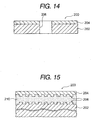
- Fig. 14 is a schematic sectional view showing a structure of a reproduction-dedicated two-layer disk.
- a reproduction-dedicated two-layer disk 200 is constituted by including a base substrate 202 having a thickness of 1.1 mm and forming a light transmission layer 204 having a thickness of 0.1 mm on either surface of the base substrate 202.
- Fig. 15 is an enlarged view of the boundary portion between the base substrate and the light transmission layer in Fig. 14.
- a spiral information pit 208 centering around a center hole 206 (refer to Fig. 14) is individually formed on the base substrate 202 and the light transmission layer 204.
- a reflection layer (not illustrated) is formed on surfaces of these information pits 208 through sputtering or vapor deposition and the like and a resin layer 210 is formed between faced information pits 208 so as to fill the irregularity due to the information pits 208.
- the two-layer disk thus constituted applies a laser beam from the upper portion of the light transmission layer 204 to perform read.
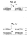
- Figs. 16 and 17 are step illustrations showing a procedure for forming an information pit by using the spin coating method.
- the base substrate 202 and a light-transmission stamper 212 are mutually attached so as to hold an ultraviolet-curing resin applied to the inner margin side of the base substrate 202 to rotate the base substrate 202 and the stamper 212 about the center hole 206 as shown by the arrow 214.
- the ultraviolet-curing resin expands toward the outer periphery of the disk in accordance with the centrifugal force and the gap between the base substrate 202 and the stamper 212 is filled with the ultraviolet-curing resin. After the gap is filled with the ultraviolet-curing resin, ultraviolet radiation is applied from the upper portion of the stamper 212 to form a resin layer 216 by curing the ultraviolet-curing resin.
- the stamper 212 is raised upward as shown in Fig. 17 to remove the stamper 212 from the resin layer 216.
- the information pit 208 transferred from the stamper 212 is exposed to the surface of the resin layer 216.
- a refection layer is formed on the surface of the resin layer 216 through sputtering or vapor deposition and then, a light transmission layer is formed through a method such as spin coating.
- the clearance of a stamper to a base substrate must be set so as to be uniform between tens of microns and hundreds of microns.
- the stamper to be attached is approached to the base substrate.
- the stamper may be tilted or warped due to the weight of the stamper or the viscous resistance of an ultraviolet-curing resin (so-called resin) previously applied to the inner margin side of a base substrate.
- the thickness of the ultraviolet-curing resin (so-called resin layer) to be cured between a disk and the stamper differs and as a result, a problem occurs that the position of an upper recording layer does not become constant in the thickness direction.
- the present invention is made to solve the above conventional problem and its object is to provide a stamper attaching method and apparatus capable of eliminating a tilt or warpage of a stamper to be attached and attaching the stamper to a disk at a uniform clearance and a multilayer recording medium manufactured by the apparatus.
- the present invention is made in accordance with the knowledge that a stamper becomes parallel with a disk and the stamper can be prevented from being warped by making tables previously plane-balanced in parallel attract backs of the disk and stamper and approaching these faced tables each other.
- a stamper attaching method of the present invention is a stamper attaching method for forming a state before a spin coating treatment by applying a resin to the inner margin side of a disk having a center hole and then attaching a stamper to the disk so as to hold the resin, which uses a procedure of fixing the disk to a spinner table while fitting the center hole to a centering member protruded from the spinner table to apply the resin to the inner margin side of the disk, putting the stamper on the disk through the resin and lowering the stamper to the disk side in accordance with the pressure of an attaching head, attracting the stamper by the attaching head after centering the stamper through fitting with the centering member, setting the clearance of the stamper to the disk when the attaching head lowers, and holding the clearance by the centering member.
- a stamper attaching apparatus of the present invention is a stamper attaching apparatus for performing centering of a disk having a center hole and a stamper and attaching by a resin and forming a state before a spin coating treatment, comprising:
- the centering member by a hollow rubber member and a medium supplying portion to be connected to the hollow rubber member, increase the diameter of the hollow rubber member by supplying a medium to the hollow rubber member from the medium supplying portion, center the disk and the stamper, and hold the protrusion direction or constitute the centering member by a hollow rubber member and a diameter increasing member which can be inserted into the hollow rubber member, increase the diameter of the hollow rubber member by inserting the diameter increasing member into the hollow rubber member, center the disk and the stamper, and hold the protrusion direction.
- a multilayer recording medium of the present invention is manufactured by the stamper attaching apparatus of any one of claims 2 to 4.
- the center hole of a disk is first fitted to a centering member protruded from a spinner table to center the disk for the spinner table. Then, the disk is centered and brought into close contact with the spinner table by activating disk attracting means. Thus, by bringing the disk into close contact with the spinner table, the disk follows the surface of the spinner table. Therefore, it is possible to prevent the disk rising or the like.
- the discharge port of the dispenser is moved to the inner margin side of the disk by activating the reciprocally moving means to apply resin to the inner margin side of the disk.
- the reciprocally moving means can use any resin as long as the resin can be cured after filling the gap between the disk and stamper. Specifically, it is preferable to use an ultraviolet-curing resin or the like.
- the stamper After applying the resin to the inner margin side of the disk, the stamper is lowered from the upper portion of the disk. Then, when the fitting degree of the center hole of the stamper and the centering member increases because the stamper lowers, axle center of the stamper coincides with the axle center of the disk. After the axle center of the disk coincides with that of the stamper, the stamper is fixed to an attaching head for pressing the stamper by activating the stamper attracting means of the attaching head. Thus, by attracting the stamper after the stamper is centered, it is possible to make the stamper approach the disk without the fact that the axle center with the disk is not shifted.
- the stamper is fixed to the attaching head, it is needless to say that the stamper always becomes parallel with the disk located below and it is possible to prevent a warpage from occurring by the weight of the stamper or viscous resistance of the resin applied to the inner margin side of the disk.
- the center hole of the stamper coincides with the axle center of the disk by deciding how long the center hole of the stamper is fitted to the centering member and the obtained value is stored by control means. Then, when the stamper exceeds this value and approaches the disk, the control means determines that the stamper is centered, the stamper attracting means fixes the stamper in accordance with a designation from the control means, and the stamper is approached to the disk up to a preset distance. Moreover, after the clearance of the stamper is set to the disk, the centering member presses an end face of the center hole of the stamper. Therefore, the height direction of the stamper is held by the centering member and the clearance with the disk is kept.
- the resin expands from the inner margin side of the disk to the outer margin side of it by rotating (spinning) the spinner table about the centering member and it is possible to form a resin layer having a constant thickness. Therefore, it is possible to keep the position of an upper recording layer constant in the thickness direction.
- the centering member is constituted by a hollow rubber member and a medium supplying portion to be continued to the hollow rubber member, it is possible to uniformly expand the hollow rubber member centering around the center by introducing a medium into the hollow rubber member from the medium supplying portion. Moreover, it is possible to center the disk and the stamper by this expansion. Furthermore, by setting the outer shape of the hollow rubber member before expansion to a value smaller than the inside diameter of the center hole, it is possible to prevent an end face of the center hole of the disk from sliding to the hollow rubber member when setting the disk to the spinner table. Thus, because extra slide does not occur, it is possible to prevent dust from being produced due to the slide or the dimension of the centering member from fluctuating.
- the peculiar effect of the hollow rubber member can be also achieved by inserting a diameter increasing member into the hollow rubber member instead of the medium supplying portion.
- a diameter increasing member can be inserted into the hollow rubber member, it is possible to eliminate the pipe laying route of the medium. It is needless to say that the force applied to the end face of the center hole is uniformed and it is possible to improve the centering accuracy in accordance with the elastic deformation of the hollow rubber member between the'end face of the center hole and the diameter increasing member.
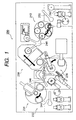
- Fig. 1 is a schematic top view of a groove forming apparatus to which a stamper attaching apparatus of this embodiment is applied as a stamper attaching portion.
- an apparatus having a stamper removing portion is used as a groove forming apparatus.
- the apparatus is not restricted to formation of a groove structure. It is also allowed to use the apparatus to form an information pit like disk go-around instead of the groove structure or form the groove structure and the information pit by combining them.
- a groove forming apparatus 230 to which the stamper attaching apparatus of this embodiment is applied as a stamper attaching portion forms a groove structure at the upper-layer recording side of a rewritable two-layer disk which provides a multilayer recording medium. Moreover, as shown in Fig.
- the groove forming apparatus 230 includes a disk-stamper supplying portion 232 for supplying a disk and a stamper, a cleaner portion 234 for cleaning the surface of the disk, stamper attaching portion 236 for attaching a stamper to the above disk, an ultraviolet applying portion 238 for curing the ultraviolet-curing resin between the disk and the stamper to form a resin layer, a stamper removing portion 240 for removing the stamper from the disk, and a disk discharging portion 242 for discharging the disk and stamper.
- a supply arm 244, first transfer arm 246, second transfer arm 248, and discharge arm 250 are set between these components so that the disk and stamper can be carried to the rear stage side in accordance with the rotation of these arms.
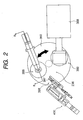
- Fig. 2 is an enlarged view of the stamper removing portion in Fig. 1
- Fig. 3 is the BB sectional view in Fig. 2
- Fig. 4 is an enlarged view of the essential portion in Fig. 3.
- the stamper attaching portion 236 is provided with a discoid attaching table 350 which can be rotated by 180° by a not-illustrated cam unit.
- the attaching table 350 is provided with a pair of spinner tables 352 about the rotation center.
- Each of the spinner tables 352 is constituted by a discoid conformation similarly to the attaching table and a whirling servomotor 354 is set under the spinner tables 352.
- the rotating shaft of the whirling servomotor 354 is connected to the central portion of the spinner tables 352 and the spinner tables 352 can be rotated by activating the whirling servomotor 354.
- an attaching head 356 and a first UV irradiator 358 are set above the attaching table 350 so as to correspond to positions of a pair of spinner tables 352.
- the stamper attaching portion 236 serving as the stamper attaching apparatus of this embodiment and a temporary-curing UV irradiator 360 are formed.
- the spinner table 352 for constituting the stamper attaching portion 236 is described below.
- the outside diameter of the discoid spinner table 352 is set to a dimension slightly smaller than the outside diameter of a disk 278 to be attached. Moreover, a 364 headed for the central portion of the spinner table 352 is formed at the side of the spinner table 352. A plurality of attraction ports 361 communicating with the bore 364 are formed on the surface of the spinner table 352 nearby the bore 364. By connecting a not-illustrated disk attraction means (so-called vacuum pump or the like) to the end opening of the bore 364, the inside of the bore 364 is brought into a negative pressure space and attraction is performed from the attraction ports 361 so that the disk 278 can be attracted by the disk attracting portion 364. A concave portion (not illustrated) is formed between bores 364 at the back of the spinner table 352 so as to decrease the weight of the spinner table 352.
- a not-illustrated disk attraction means so-called vacuum pump or the like
- a cylindrical hollow rubber member 370 constituting a centering member is set so as to protrude from the central portion of the table 352 and a diameter increasing member 372 is set in the hollow rubber member 370.
- the diameter increasing member 372 is set along the inner wall of the hollow rubber member 370 and a pressing wall 374 movable in the radius direction of the hollow rubber member and a center pin 376 to be protruded upward along the shaft center of the hollow rubber member 370 in the pressing wall 374 are arranged.
- the diameter of the pressing wall 374 is increased, the hollow rubber member 370 is pressed against the sidewall of the center hole of the disk 278, and the disk 278 is centered for the hollow rubber member 370.
- a guide plate 378 is set outside of the spinner table 352 so as to surround the spinner table 352. Moreover, when the guide plate 378 surrounds the spinner table 352, it is possible to prevent dust from coming from the outside of the stamper attaching portion 236 and depositing on the surface of the disk 278 attracted by the spinner table 352.
- the attaching head 356 forming the stamper attaching portion 236 is constituted as described below.
- the attaching head 236 is constituted by a disk having a flange portion 382 and a stamper setting face 384 for closely contacting the stamper 280 through attraction is formed at the small diameter side of the head 236 facing the spinner table 352.
- the stamper setting face 384 is formed so that the outside diameter of it becomes slightly larger than the outside diameter of the stamper 280 so that the entire surface of the stamper 280 can be pressed by the attaching head 236.
- a depression 390 is formed at the side facing an attaching plate 388 combined to vertically move the attaching head 236 at the opposite side to the stamper setting face 384 on the attaching head 236 to form an air attracting route connected to stamper attracting means (so-called vacuum pump or the like not illustrated) set to the attaching plate 388 by setting the attaching head 236 to the attaching plate 388.
- stamper attracting means so-called vacuum pump or the like not illustrated
- the depression 390 has a complex shape. Therefore, it is allowed to form the attaching head 236 by not only a method of machining the attaching head 236 but also a sintering method.
- a ball screw connecting with a vertically-moving servomotor 391 and a single-axis unit 394 constituted by a vertically-moving stage 392 capable of reciprocally moving in accordance with the rotation of the ball screw are vertically set to the side of the attaching head 236 thus constituted.
- a connecting arm 396 is set between the vertically-moving stage 392 and the attaching plate 388 to vertically move the attaching plate 388 together with the vertically-moving stage 392.
- a dispenser 398 having a discharge nozzle 397 at its front end is set to a position not interfering with the single-axis unit 394 around the spinner table 352.
- a ball screw mechanism 400 serving as reciprocally moving means through servomotor driving is set to the dispenser 398.
- the dispenser 398 is advanced by activation of the ball screw mechanism 400 so that an ultraviolet-curing resin which becomes a resin by the discharge nozzle 397 can be applied to the inner margin of the disk 278.
- Rotation of the above-described attaching table 350, the whirling servomotor 354, vertically-moving servomotor 391, disk and stamper attracting means, and dispenser 398 are all connected to not-illustrated control means and rotation and vertical movement or the like are performed in accordance with an activation signal from the control means.
- a procedure for attaching the stamper 280 to the disk 278 is described below by using the groove forming apparatus 230 thus constituted.
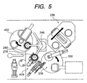
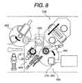
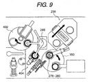
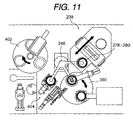
- Figs. 5 to 11 are a state illustration showing a state in which a disk and a stamper pass through a stamper attaching portion.
- the disk 278 is transferred to a stamper reversing chuck 404 from the cleaner portion 234 by using the first transfer arm 246. Then, as shown in Fig. 6, the disk 278 held by the stamper reversing chuck 404 is transferred to the spinner table 352 by rotating the first transfer arm 246 again and the stamper 280 mounted on the cleaner portion 234 is transferred to the stamper reversing chuck 404.
- the first transfer arm 246 can vertically move (paper thickness direction in Fig. 6) in accordance with its rotation.
- the arm portion of the first transfer arm 246 presses the center pin 376 protruded from the spinner table 352 when the first transfer arm 246 lowers and the pressing wall 374 expands in the diameter direction when the center pin 376 lowers to press the inner wall of the center hole of the disk 278 through the hollow rubber member 370. Therefore, the disk 278 is centered so as to coincide with the rotation center of the spinner table 352 and the disk 278 is brought into close contact with the surface of the spinner table 352 in accordance with the negative pressure by the disk attracting means.
- the control means determines that the disk 278 is mounted on the spinner table 352 in accordance with the rotation of the first transfer arm 246 and then, activates the disk attracting means, and attracts the disk 278.
- the control means activates the ball screw mechanism 400 and advances the dispenser 398.
- the discharge nozzle 397 set to the front end of the dispenser 398 reaches the inner margin side of the disk 278, it stops the ball screw mechanism 400, rotates the disk 278 by activating the whirling servomotor 354, discharges an ultraviolet-curing resin from the front end of the discharge nozzle 397, and applies the ultraviolet-curing resin to the inner margin side of the disk 278.
- the stamper 280 is put above the disk 278 from the stamper reversing chuck 404 by rotating the first transfer arm 246 again.
- the center hole of the stamper 280 contacts with the outer surface of the hollow rubber member 370 whose outside diameter is expanded by the pressing wall 374 and the stamper 280 is held by the hollow rubber member 370 while keeping a sufficient distance from the disk 278.
- Fig. 7 shows a state in which the disk 278 overlaps with the hollow rubber member 280.
- the attaching head 356 constituting the stamper attaching portion 236 together with the spinner table 352 waits above so as to have a sufficient distance from the spinner table 352. Therefore, even if the first transfer arm 246 moves to the upper portion of the spinner table 352, the height-directional position of the arm 246 becomes the lower side of the attaching head 356 and it is possible to prevent that the both interfere each other.
- control means activates the vertically-moving servomotor 391 and lowers the attaching head 356 toward the stamper 280 together with the vertically-moving stage 392, connecting arm 396, and attaching plate 388.
- Fig. 12 is a graph showing a relation between lowering distances of an attaching head and times.
- the height of the attaching head 356 from the stamper attaching position is set to 200 mm as shown by the point A in Fig. 12 when the first transfer arm 246 enters the upper portion of the spinner table 352.
- the attaching head 356 lowers from the position of the point A up to the automatic operation waiting position (100 mm) shown by a point B in 2 sec and then, lowers from the position of the point B up to the contact position (5 mm) with the stamper 280 shown by a point C in 2 sec.
- the descending speed is decreased to lower the head 356 up to the stamper attaching height shown by a point E at a constant speed.
- the stamper 280 located at the middle of the hollow rubber member 370 lowers together with the attaching head 356, the stamper 280 is centered by the hollow rubber member 370 at the height of a point D (1 mm) the same as the case of the disk 278. It is possible to optionally set the height of the point D in accordance with the specification of the stamper 280 or other reason and it is only necessary to freely set the height in accordance with the expansion degree of the diameter increasing member 372 set inside of the hollow rubber member 370.
- the control means activates the stamper attracting means and attracts the stamper 280 to the stamper setting face 384.
- the time when the attaching head 356 reaches from the point C to the point D is set to 4 sec.
- the stamper 280 is centered by the hollow rubber member 370 as described above. Therefore, it is only necessary to attract the stamper 280 to the stamper setting face 384 and lower the stamper 280 up to a previously-set attaching height shown by the point E in Fig. 12 while holding the centering position of the stamper 280 (while holding the radius-directional position).
- the attaching height of the stamper 280 to the disk 278 is optionally set to a value between tens of microns and hundreds of microns.
- the attaching head 356 reaches the point E and the attaching height of the stamper 280 to the disk 278 is set, the attaching head 356 is raised from a point F to a point G.
- the stamper attracting means is stopped by the control means so that the attaching head 356 can be easily separated from the stamper 280.
- the attaching table 350 is rotated by 180° and the disk 278 and stamper 280 attached together are moved to the temporary UV irradiating portion 360 together with the spinner table 350.
- the disk 278 and stamper 280 attached together are rotated by the temporary UV irradiating portion 360, the diameter of an ultraviolet-curing resin is increased by the centrifugal force of the rotation of them from the inner margin side of the disk outward and the gap between the disk 278 and the stamper 280 is filled with the ultraviolet-curing resin.
- the first UV irradiator 358 is activated together with the spinning treatment, ultraviolet radiation is applied to the ultraviolet-curing resin through the stamper 280 to cure the ultraviolet-curing resin up to a degree at which the thickness does not fluctuate (so-called temporary curing step).
- the pressing wall 374 and center pin 376 are set in the hollow rubber member 370 to increase the diameter of the hollow rubber member 370.
- it is also allowed to use another conformation.
- Fig. 13 is a sectional view showing another conformation of a centering member. Because portions other than the centering member have the same as those of the above-described spinner table 352, the same number is provided for a common portion and the common portion is described.
- a bag-like hollow rubber member 406 is set to the spinner table 352 so as to protrude from the central portion of the table 352. Moreover, a pair of air pipes 408 to be connected to the hollow rubber member 406 are set below the hollow rubber member 406. The other end of the air pipe 408 is connected to a not-illustrated pressure supplying means.
- the diameter of the hollow rubber member 406 can be increased by introducing air into the hollow rubber member 406, the outside diameter of the hollow rubber member 406 can be decreased by discharging air from the inside of the hollow rubber member 406, and the disk 278 can be easily centered or taken out.
- the present inventor used silicon rubber as the material of the hollow rubber member by noticing that the silicon rubber has a characteristic that it is superior in abrasion resistance and it has a small hardness change even if temperatures are changed. However, it is also allowed to select an optional material in accordance with a purpose or operating environment.
- a stamper is overlapped on a disk and then, the stamper is lowered to the disk side in accordance with the pressure of an attaching head. Then, the stamper is centered in accordance with fitting with a centering member and attracted by the attaching head.
Landscapes
- Engineering & Computer Science (AREA)
- Mechanical Engineering (AREA)
- Manufacturing & Machinery (AREA)
- Robotics (AREA)
- Manufacturing Optical Record Carriers (AREA)
- Lining Or Joining Of Plastics Or The Like (AREA)
- Casting Or Compression Moulding Of Plastics Or The Like (AREA)
Abstract
Description
Claims (5)
- A stamper attaching method for attaching stamper so as to hold a resin after applying the resin to the inner margin side of a disk having a center hole, comprising:a step of fixing the disk to a spinner table while fitting the center hole to a centering member protruded from the spinner table to apply the resin to the inner margin side of the disk;a step of fitting the centering member to the center hole of the stamper;a step of overlapping the stamper on the disk through the resin and lowering the stamper up to the disk side in accordance with the pressure of an attaching head;a step of attracting the stamper by the attaching head after the stamper is centered in accordance with fitting with the centering member; anda step of setting a clearance of the stamper to the disk when the attaching head lowers and holding the clearance by the centering member.
- A stamper attaching apparatus for centering a disk having a center hole and a stamper and attaching them together by a resin to form a state before spin coating treatment, comprising:a spinner table having disk attracting means and capable of entirely attracting the entire either side of the disk;a centering member protruded from the spinner table to center the disk and the stamper and hold the protruding direction;a dispenser having reciprocally moving means and capable of supplying the resin to the inner margin side of the disk;an attaching head having stamper attracting means and making it possible to entirely attract either side of the stamper and capable of vertically moving on the spinner table; andcontrol means for setting a clearance of the stamper to the disk by making the stamper approach the spinner table in accordance with lowering of the attaching head and brining the stamper in close contact with the attaching head in accordance with activation of the stamper attracting means after the stamper is centered in accordance with fitting of the center hole to the centering member.
- The stamper attaching apparatus according to claim 2, characterized in that
the centering member is constituted by a hollow rubber member and a medium supplying portion to be connected to the hollow rubber member and the diameter of the hollow rubber member is increased by supplying a medium to the hollow rubber member from the medium supplying portion to center the disk and the stamper and hold the protruding direction. - The stamper attaching apparatus according to claim 2, characterized in that
the centering member is constituted by a hollow rubber member and a diameter increasing member which can be inserted into the hollow rubber member, the diameter of the hollow rubber member is increased by inserting the diameter increasing member into the hollow rubber member, the disk and the stamper are centered, and the protruding direction is held. - A multilayer recording medium manufactured by the stamper attaching apparatus of any one of claims 2 to 4.
Applications Claiming Priority (3)
| Application Number | Priority Date | Filing Date | Title |
|---|---|---|---|
| JP2002133742 | 2002-05-09 | ||
| JP2002133742A JP4118083B2 (en) | 2002-05-09 | 2002-05-09 | Stamper laminating method and apparatus |
| PCT/JP2003/005803 WO2003096332A1 (en) | 2002-05-09 | 2003-05-09 | Stamper sticking method and device, and multi-layer recording medium |
Publications (2)
| Publication Number | Publication Date |
|---|---|
| EP1505586A1 true EP1505586A1 (en) | 2005-02-09 |
| EP1505586A4 EP1505586A4 (en) | 2006-08-23 |
Family
ID=29416682
Family Applications (1)
| Application Number | Title | Priority Date | Filing Date |
|---|---|---|---|
| EP03723283A Withdrawn EP1505586A4 (en) | 2002-05-09 | 2003-05-09 | Stamper sticking method and device, and multi-layer recording medium |
Country Status (6)
| Country | Link |
|---|---|
| EP (1) | EP1505586A4 (en) |
| JP (1) | JP4118083B2 (en) |
| KR (1) | KR100745622B1 (en) |
| CN (1) | CN1315123C (en) |
| TW (1) | TWI227890B (en) |
| WO (1) | WO2003096332A1 (en) |
Families Citing this family (4)
| Publication number | Priority date | Publication date | Assignee | Title |
|---|---|---|---|---|
| JPH0739658U (en) * | 1993-12-27 | 1995-07-18 | シンコハンガー株式会社 | Multi-stage hanger |
| JP2006286165A (en) * | 2005-03-09 | 2006-10-19 | Ricoh Co Ltd | Disc centering device and disc centering method |
| US8376013B2 (en) | 2008-03-11 | 2013-02-19 | Duke University | Plasmonic assisted systems and methods for interior energy-activation from an exterior source |
| US10391723B2 (en) | 2017-08-31 | 2019-08-27 | The Boeing Company | Rotary compaction tool |
Family Cites Families (20)
| Publication number | Priority date | Publication date | Assignee | Title |
|---|---|---|---|---|
| DE3004810A1 (en) * | 1980-02-09 | 1981-08-20 | Bayer Ag, 5090 Leverkusen | DEVICE FOR DIFFERENTIAL THERMAL ANALYSIS |
| US4472124A (en) | 1980-09-05 | 1984-09-18 | Matsushita Electric Industrial Co., Limited | Device for producing an information recording disk |
| JPS58173625A (en) * | 1982-04-07 | 1983-10-12 | Toshiba Corp | Reproductive preparation of information disk |
| JPS58173626A (en) * | 1982-04-07 | 1983-10-12 | Toshiba Corp | Reproductive preparation of information disk |
| JPS60167144A (en) * | 1984-02-09 | 1985-08-30 | Toshiba Corp | Production for information recording carrier |
| JPS60187517A (en) * | 1984-03-05 | 1985-09-25 | Matsushita Electric Ind Co Ltd | Information record carrier duplication device |
| JPH0650578B2 (en) * | 1985-11-22 | 1994-06-29 | 松下電器産業株式会社 | Information carrier disk manufacturing method and manufacturing apparatus thereof |
| JPS63154308A (en) * | 1986-12-19 | 1988-06-27 | Hitachi Ltd | Replica device |
| JP2509979B2 (en) * | 1988-04-27 | 1996-06-26 | グローバルマシーナリー株式会社 | Optical information recording medium manufacturing apparatus |
| DE68927617T2 (en) * | 1988-04-27 | 1997-06-05 | Dainippon Ink & Chemicals | Device for producing an optical information recording medium |
| NL9002517A (en) * | 1990-11-19 | 1992-06-16 | Philips Nv | METHOD FOR MANUFACTURING AN OPTICALLY READABLE PLATE AND APPARATUS FOR CARRYING OUT THE METHOD |
| JPH0981975A (en) * | 1995-09-08 | 1997-03-28 | Sony Disc Technol:Kk | Production of optical disk |
| JP3713773B2 (en) * | 1995-12-04 | 2005-11-09 | ソニー株式会社 | Manufacturing method of optical recording medium |
| JPH09231619A (en) * | 1996-02-23 | 1997-09-05 | Sony Corp | Method for manufacturing optical recording medium and apparatus used therefor |
| JPH10261246A (en) * | 1997-03-18 | 1998-09-29 | Seiko Epson Corp | Manufacturing method of information recording carrier |
| JPH1131338A (en) * | 1997-07-10 | 1999-02-02 | Sony Corp | Manufacturing method of optical recording medium |
| JPH11273165A (en) * | 1998-03-24 | 1999-10-08 | Dainippon Ink & Chem Inc | Disk transport method, disk transport device, and disk manufacturing method |
| AU744721B2 (en) * | 1998-09-28 | 2002-02-28 | Wea Manufacturing Inc. | Dual-layer DVD disc, and method and apparatus for making same |
| JP3411530B2 (en) * | 1999-05-31 | 2003-06-03 | オリジン電気株式会社 | Method and apparatus for manufacturing information disk |
| JP2003173580A (en) * | 2001-12-05 | 2003-06-20 | Matsushita Electric Ind Co Ltd | Optical information recording medium transport carrier and optical information recording medium manufacturing method using the same |
-
2002
- 2002-05-09 JP JP2002133742A patent/JP4118083B2/en not_active Expired - Fee Related
-
2003
- 2003-05-06 TW TW092112350A patent/TWI227890B/en not_active IP Right Cessation
- 2003-05-09 EP EP03723283A patent/EP1505586A4/en not_active Withdrawn
- 2003-05-09 WO PCT/JP2003/005803 patent/WO2003096332A1/en not_active Ceased
- 2003-05-09 KR KR1020047017936A patent/KR100745622B1/en not_active Expired - Fee Related
- 2003-05-09 CN CNB038105233A patent/CN1315123C/en not_active Expired - Fee Related
Also Published As
| Publication number | Publication date |
|---|---|
| WO2003096332A1 (en) | 2003-11-20 |
| TWI227890B (en) | 2005-02-11 |
| KR100745622B1 (en) | 2007-08-03 |
| EP1505586A4 (en) | 2006-08-23 |
| JP2003331483A (en) | 2003-11-21 |
| CN1315123C (en) | 2007-05-09 |
| TW200402053A (en) | 2004-02-01 |
| KR20040111586A (en) | 2004-12-31 |
| CN1653534A (en) | 2005-08-10 |
| JP4118083B2 (en) | 2008-07-16 |
Similar Documents
| Publication | Publication Date | Title |
|---|---|---|
| JP2002316084A (en) | Spin coating apparatus using mask and mask for spin coating | |
| EP1030779A1 (en) | System and method for thermally manipulating a combination of a top and bottom substrate before a curing operation | |
| EP1508898A1 (en) | Multi-layer recording medium forming method and device, and multi-layer recording medium | |
| US20040219326A1 (en) | Method of manufacturing multilayer optical recording medium and multilayer optical recording medium | |
| JP4118083B2 (en) | Stamper laminating method and apparatus | |
| US20040196777A1 (en) | Method and device for manufacturing optical recording medium | |
| US6098272A (en) | System for maintaining concentricity of a combination of a top and bottom substrate during the assembly of a bonded storage disk | |
| KR20060026665A (en) | Turntable Device for Spin Coating | |
| JP4076120B2 (en) | Spin coating method and apparatus | |
| WO2003028024A1 (en) | Method for producing multilayer optical recording medium and system for producing multilayer optical recording medium | |
| JP2005317053A (en) | Manufacturing method of optical disk, and optical disk device | |
| US6478908B1 (en) | Production method of and production apparatus for optical recording disc | |
| JP2004145984A (en) | Method for manufacturing multilayer optical disk and apparatus for manufacturing multilayer optical disk | |
| TW579303B (en) | Spin coating method and apparatus, and mask used in the same method and apparatus | |
| JPH10255339A (en) | Method and apparatus for manufacturing optical bonded disc | |
| EP1164009A2 (en) | System and method for curing a resin disposed between a top and bottom substrate with thermal management | |
| JP2006114092A (en) | Manufacturing apparatus and manufacturing method of disk type recording medium | |
| WO2010070747A1 (en) | Transfer apparatus and transfer method | |
| EP1561576B1 (en) | Correcting stage, apparatus and method for laminating and laminated recording medium | |
| JP2000306324A (en) | Master disc device | |
| JP2005302206A (en) | Manufacturing method of information recording medium and information recording medium manufacturing apparatus | |
| JP2006114093A (en) | Lamination apparatus of disk substrate and lamination method | |
| WO1999024239A1 (en) | System and method for distributing a resin disposed between a top substrate and a bottom substrate | |
| JPS6392438A (en) | Apparatus for forming transfer layer of information recording disc | |
| WO1999024336A1 (en) | System and method for maintaining concentricity of a combination of a top and bottom substrate during the assembly of a bonded storage disk |
Legal Events
| Date | Code | Title | Description |
|---|---|---|---|
| PUAI | Public reference made under article 153(3) epc to a published international application that has entered the european phase |
Free format text: ORIGINAL CODE: 0009012 |
|
| 17P | Request for examination filed |
Effective date: 20041125 |
|
| AK | Designated contracting states |
Kind code of ref document: A1 Designated state(s): DE NL |
|
| AX | Request for extension of the european patent |
Extension state: AL LT LV MK |
|
| DAX | Request for extension of the european patent (deleted) | ||
| A4 | Supplementary search report drawn up and despatched |
Effective date: 20060721 |
|
| RIC1 | Information provided on ipc code assigned before grant |
Ipc: B29C 43/02 20060101ALI20060717BHEP Ipc: B29C 31/00 20060101ALI20060717BHEP Ipc: B29C 33/30 20060101ALI20060717BHEP Ipc: G11B 7/24 20060101ALI20060717BHEP Ipc: G11B 7/26 20060101AFI20031126BHEP |
|
| 17Q | First examination report despatched |
Effective date: 20081104 |
|
| STAA | Information on the status of an ep patent application or granted ep patent |
Free format text: STATUS: THE APPLICATION IS DEEMED TO BE WITHDRAWN |
|
| 18D | Application deemed to be withdrawn |
Effective date: 20090317 |