EP1505550A1 - Mechanism and method for generating a haptic signal - Google Patents
Mechanism and method for generating a haptic signal Download PDFInfo
- Publication number
- EP1505550A1 EP1505550A1 EP03425531A EP03425531A EP1505550A1 EP 1505550 A1 EP1505550 A1 EP 1505550A1 EP 03425531 A EP03425531 A EP 03425531A EP 03425531 A EP03425531 A EP 03425531A EP 1505550 A1 EP1505550 A1 EP 1505550A1
- Authority
- EP
- European Patent Office
- Prior art keywords
- force vector
- signal
- activation signal
- vibration element
- generating
- Prior art date
- Legal status (The legal status is an assumption and is not a legal conclusion. Google has not performed a legal analysis and makes no representation as to the accuracy of the status listed.)
- Granted
Links
Images


Classifications
-
- B—PERFORMING OPERATIONS; TRANSPORTING
- B06—GENERATING OR TRANSMITTING MECHANICAL VIBRATIONS IN GENERAL
- B06B—METHODS OR APPARATUS FOR GENERATING OR TRANSMITTING MECHANICAL VIBRATIONS OF INFRASONIC, SONIC, OR ULTRASONIC FREQUENCY, e.g. FOR PERFORMING MECHANICAL WORK IN GENERAL
- B06B1/00—Methods or apparatus for generating mechanical vibrations of infrasonic, sonic, or ultrasonic frequency
- B06B1/02—Methods or apparatus for generating mechanical vibrations of infrasonic, sonic, or ultrasonic frequency making use of electrical energy
-
- G—PHYSICS
- G08—SIGNALLING
- G08B—SIGNALLING OR CALLING SYSTEMS; ORDER TELEGRAPHS; ALARM SYSTEMS
- G08B6/00—Tactile signalling systems, e.g. personal calling systems
Definitions
- the invention relates to a mechanism and method for generating a haptic signal and in particular to a mechanism and method for a portable device.
- a vibration signal may be generated when an incoming call is received thereby alerting a user.
- Vibration alerts are typically implemented by use of a vibration motor.
- a vibration motor generates a vibration signal by rotating a mass offset from the rotational axis in response to an electrical signal.
- vibration motors tend to be relatively bulky and to have relatively high power consumption.
- a vibration motor furthermore comprises moving parts and is mechanically relatively fragile. Furthermore, the vibration movement is limited and the tactile signal that may be generated is consequently limited and inflexible.
- the multi function transducer may provide the same acceleration and force magnitudes as a motor alert, empirical tests on a large population and with many different coupling configurations have shown that a multi function transducer is not capable of attracting the average human operator's attention as effectively as a motor alert. Thus, the multi function transducer tends to provide a single rectilinear vibration signal which has a significantly lower psychophysical effectiveness.
- an improved system for generating a haptic signal and in particular a haptic alert signal, would be advantageous.
- a system allowing for increased flexibility, reduced complexity, reduced size, reduced power consumption, reduced cost, increased reliability and high psychophysical effect would be advantageous.
- the Invention seeks to mitigate, alleviate or eliminate one or more of the above mentioned disadvantages singly or in any combination.
- a mechanism for generating a haptic signal in a portable device comprising: a first vibration element operable to generate a varying first force vector in a substantially first direction in response to a first activation signal; a second vibration element operable to generate a varying second force vector in a substantially second direction in response to a second activation signal; wherein the first vibration element is mounted relative to the second vibration element such that the first direction is at an angle with respect to the second direction whereby a combined force vector of the first and second force vector may perform an angular movement.
- the invention allows for substantially rectilinear force vectors generated by the first and second vibration elements to combine such as to generate a force vector which performs an angular movement and is not limited to the directions of the rectilinear force vectors.
- the first and second vibration elements may be controlled by the first and second activation signal such that the combined force vector performs a desired movement.
- the first and second activation signals may be such that the psychophysical effect is increased or maximised.
- Many possible haptic signals may be generated depending on the activation signals and thus a high degree of flexibility is achieved. For example, different activation signals and thus different haptic signals may be generated in different situations.
- the invention allows for a range of different haptic signals to be generated simply by generating different activation signals.
- the flexibility allows for the haptic signal to be optimised for the psychophysical effect such that an effective haptic alert signal may be generated.
- the invention may allow for the generation of a haptic or tactile signal having a rotating force vector, according to a defined time function, which furthermore has a rotating application point. Empirical tests have shown that this enables an effective psychophysical alert signal.
- a vibration motor of a portable device may be replaced by two substantially rectilinear vibration elements without reducing the psychophysical effectiveness.
- the vibration elements may be coupled and controlled such as to emulate the haptic sensation of a vibration motor and provide an equivalent psychophysical effect.
- a vibration motor may be replaced by simpler vibration elements thereby allowing for a reduction in power, complexity, cost and increased reliability of not just the mechanism for generating the haptic signal but also of the device in which the mechanism is included.
- the varying of the first force vector is an oscillating movement.
- the second force vector may also perform an oscillating movement. This allows for simple vibration elements and/or simple activation signals while providing a haptic signal having a high psychophysical effect.
- the angular movement of the combined force vector is a rotational movement. Empirical tests have shown that this enables a haptic signal having a high psychophysical effect.
- the haptic signal may furthermore be similar to a haptic signal that may be generated by a vibration motor.
- the first vibration element is a multifunction transducer.
- the second element may preferably also be a multi function transducer. This allows for a dual functionality of the vibration elements thereby allowing for a reduction of size, cost, complexity and or weight of a device comprising the mechanism.
- the first vibration element is further operable to generate an audio signal in response to the first activation signal.
- the first vibration element may be a multi function transducer operable to generate sound.
- the multi function transducer may thus be used both for generating sound as well as for generating the haptic signal.
- the second vibration element may also be operable to generate an audio signal in response to the second activation signal.
- the second vibration element may be a multi function transducer operable to generate sound.
- the multi function transducer may thus be used both for generating sound as well as for generating the haptic signal. If both vibration elements are multi function transducers operable to generate sound, a biphonic sound signal may be generated (e.g. a stereo sound). This is likely to be a highly desired feature of for example mobile phones.
- the same multi function transducers may furthermore provide an effective haptic alert signal which may specifically emulate a haptic signal from a vibration motor.
- the mechanism further comprises means for generating an audio activation signal and the first vibration element is further operable to generate an audio signal in response to the audio activation signal.
- An audio activation signal may be generated and used to control the multi function transducer such as to generate a desired sound.
- a sound generator may generate an audio alert signal
- a music processor may generate a music signal
- a receiver may generate an audio signal from a received communication signal.
- the multi function transducer may be used for not only generating an audio signal in response to the activation signal but also to generate other sounds.
- the multi function transducers may be the only means of sound generation in the device comprising the mechanism. Hence, a very simple device is achieved comprising only the multi function transducers for generating both sound and haptic signals.
- the first vibration element is mounted relative to the second vibration element such that the first direction is offset by substantially 90 degrees with respect to the second direction.
- This allows for a particularly advantageous movement of the combined force vector and may specifically allow for a substantially constant momentum.
- the activation signals may be such that the combined force vector rotates while having a substantially constant magnitude.
- a rotating application point may be achieved.
- the second activation signal corresponds to a delayed version of the first signal. This allows for suitable activation signals which are simple to generate and control.
- the first activation signal is a substantially sinusoidal signal. This allows for suitable activation signals which are simple to generate and control. Specifically, it may allow for a rotating but constant magnitude combined force vector.
- the second activation signal is a substantially sinusoidal signal offset by substantially 90 degrees. This allows for suitable activation signals which are simple to generate and control. Specifically, it may allow for a rotating but constant magnitude combined force vector.
- a frequency of the first activation signal is substantially equal to a resonance frequency of the first vibration element.
- the first activation signal may be such that it (at least) for a proportion of the time is substantially equal to the resonance frequency of the first vibration element. This will allow for the resulting force vector to have an increased or maximised magnitude thus increasing the strength of the haptic alert signal.
- a frequency of the second activation signal may also preferably be substantially equal to a resonance frequency of the second vibration element, at least for a proportion of the time.
- the mechanism further comprises means for varying a frequency of the first activation signal.
- the means for varying the frequency is operable to frequency modulate the first activation signal.
- the frequency modulation may for example result in a repeating frequency sweep over a frequency range in which the resonance frequency of the first vibration element is likely to be. This allows for an activation signal which has a high probability of matching the resonance frequency of the first vibration element for at least part of the duration of the activation signal.
- the resonance frequency of a vibration element may depend on e.g. manufacturing tolerances, the exact resonance frequency is generally not known. This uncertainty is mitigated by sweeping the frequency of the activation signal over the frequency tolerance range.
- the mechanism is preferably comprised in portable device.
- the invention allows for a portable device having low complexity, low cost, high flexibility, low size and/or weight and which is able to generate an efficient haptic signal.
- the portable device is a personal communication device.
- the personal communication device may for example be a mobile phone.
- the personal communication device further comprises means for detecting an incoming call and means for generating the first and second activation signal in response to the detection of the incoming call.
- the invention allows for a low complexity personal communication device which may generate an efficient haptic alert signal in response to an incoming call.
- a method of generating a haptic signal in a portable device comprising: generating a varying first force vector in a substantially first direction in response to a first activation signal; generating a varying second force vector in a substantially second direction in response to a second activation signal; wherein the first direction is at an angle with respect to the second direction whereby a combined force vector of the first and second force vector performs an angular movement.
- the first and second force vectors may result in a combined rotating force vector having a rotating application point.
- FIG. 1 illustrates a mechanism 100 for generating a haptic signal in a portable device in accordance with an embodiment of the invention.
- the mechanism 100 comprises a first vibration element 101 which may generate a varying first force vector 103 when an alternating electrical signal is supplied to the vibration element 101.
- the vibration element 101 is operable to generate a substantially rectilinear force vector.
- the first force vector 103 in the example of FIG. 1 thus extends substantially in a first direction 105.
- the first force vector 103 is substantially rectilinear, the magnitude and preferably sign of the first force vector 103 varies.
- the first force 103 vector is aligned with the first direction105 but the effective force generated by the vibration element 101 may be towards either end of the first direction 105.
- the mechanism 100 comprises a second vibration element 107 which may generate a varying second force vector 109 when an alternating electrical signal is supplied to the second vibration element 107.
- the second vibration element 107 is operable to generate a substantially rectilinear force vector.
- the second force vector 109 in the example of FIG. 1 thus extends substantially in a second direction 111. Similar to the first force vector 103, the second force vector 109 has a varying magnitude and preferably sign and the effective force generated by the second vibration element 107 may be towards either end of the second direction 111.
- the first vibration element 101 and second vibration element 107 are mounted in the portable device such that the first direction105 and the second direction 111 are at an angle with respect to each other.
- the axes of the first direction105 and the second direction 111 will intersect thereby forming an angle ⁇ with each other. Accordingly, the first force vector 103 and the second force vector 109 are generated in different directions relative to the orientation of the portable device.
- the first vibration element 101 and the second vibration element 107 are furthermore mounted such that the first force vector 103 and the second force vector 109 add up to generate a combined force vector.
- both the first force vector 103 and the second force vector 109 may be substantially rigidly coupled to the portable device such that both the first force vector 103 and the second force vector 109 act directly on the portable device.
- the resulting force vector acting on the portable device is the combined force vector which in this embodiment is the sum of the first force vector 103 and the second force vector 109.
- the combined force vector resulting from a summation of the first and second force vector 103, 109 is generally in a different direction than the first direction105 or the second direction 111 (except for the specific situation where either the first force vector 103 or the second force vector 109 has zero magnitude).
- the direction of the combined force vector depends on the relative magnitudes of the first force vector 103 and the second force vector 109 as these add up. Since the force vectors vary, the direction of the combined force vector also varies (provided that the variations of the first force vector 103 and second force vector 109 are not identical). Accordingly, the combined force vector performs an angular movement.
- the mechanism 100 is thus operable to generate a combined force vector which is not limited to the first direction105 or the second direction 111 but which moves in the angular domain.
- the magnitude, application point and direction of the combined force vector depend on the mechanical mounting characteristics of the first vibration element 101 and second vibration element 107. It furthermore depends on the electrical signals applied to the vibration elements 101, 107 and may thus be controlled simply by generating suitable electrical activation signals and supplying these to the vibration elements 101, 107.
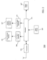
- FIG. 2 illustrates a simplified block diagram of a personal communication device 200 in accordance with a preferred embodiment of the invention.
- the personal communication device 200 comprises a processor 201 which controls the operation of the personal communication device 200.
- the processor 201 thus performs the operations required or desired for the operation of the personal communication device 200 including controlling other hardware functional modules.
- the processor 201 is coupled to a transceiver module 203 which is operable to transmit and receive radio signals.
- the processor 201 implements most of the functionality required for the personal communication device 200 to communicate in accordance with the requirements of the specific communication protocol including source encoding, data segmentation, control signalling, error management etc as will be known to the person skilled in the art.
- the transceiver module 203 performs amplification, frequency translation and conversion between the analogue and digital domain. Specifically, the conversion between the analogue and digital domain may be at an intermediate frequency thus allowing most of the modulation and demodulation to be performed by the processor 201.
- the processor 201 is further coupled to an input module 205 which is operable to receive a user input and couple this, to the processor 201.
- the input module 205 may specifically comprise a keyboard which may be operated by a user.
- the processor 201 is further coupled to an output module 207.
- the processor 201 may control the output module 207 to generate a suitable output to a user.
- the output module 207 may specifically comprise a display for generating a visual display.
- the processor 201 is also coupled to a first activation signal generator 209 which is operable to generate a first activation signal.
- the first activation signal generator 209 is coupled to the first vibration element 101 of the mechanism of FIG. 1.
- the first vibration element 101 is operable to vibrate and thus to generate a substantially rectilinear force vector in response to the first activation signal.
- the processor 201 is also coupled to a second activation signal generator 211 which is operable to generate a second activation signal.
- the second activation signal generator 211 is coupled to the second vibration element 107 of the mechanism of FIG. 1.
- the second vibration element 107 is operable to vibrate and thus to generate a substantially rectilinear force vector in response to the second activation signal.
- the main processor 201 or controller of a personal communication device is thus operable to control the mechanism of FIG. 1 to produce a haptic signal.
- the personal communication device 200 may receive an incoming call. This will be detected by the processor 201 which in return may control the first activation signal generator 209 and the second activation signal generator 211 to generate a first activation signal and a second activation signal.
- the activation signals drive the vibration elements 101, 107 to generate a haptic signal which may alert the user to the incoming call.
- the processor 201 may specifically control the signal generators 209, 211 such that a desired haptic signal is generated. Specifically, a haptic signal maximising the psychophysical effect for a given amplitude of the generated forces may be produced.
- the processor 201 is operable to generate different haptic signals dependent on the cause of the haptic signal. For example, one haptic signal may be generated in response to a detection of an incoming call and a different haptic signal may be generated in response to for example an alarm of a calendar application.
- the signal generators 209, 211 comprise Digital-to-Analogue converters which are operable to generate an analogue signal in response to digital values received from the processor 201.
- the digital values are suitably amplified (or buffered) by an analogue amplifier of the signal generators 209, 211 to generate suitable electrical activation signals for the vibration elements.
- the processor 201 may in this embodiment directly output digital data values corresponding to the desired activation signals.
- a desired waveform may be stored in memory of the processor 201 as a sequence of digital data values.
- these data values may be read out to the Digital-to-Analogue converters of the signal generators 209, 211 thereby resulting in the desired activation signals being generated.
- the vibration elements are multi function transducers capable of producing not only a force vector but also a sound signal.
- Multi function transducers in accordance with the preferred embodiment are devices that incorporate a loudspeaker and a linear vibrator into one package.
- the magnet structure is not mechanically 'grounded', has its own suspension system tuned to a low frequency and may be moved by a varying electromagnetic field generated in response to the activation signals in the frequency region of the magnet suspension resonance.
- the magnetic element comprises a mass which, when accelerated by the electromagnetic field, generates a force vector. The movement of the magnetic element is constrained to a substantially linear movement thereby resulting in a substantially rectilinear force vector.
- the magnet structure behaves as if it were grounded and the whole system behaves like a traditional loudspeaker in which the vibration of a diaphragm generates a sound signal.
- the activation signals can result not only in a force vector being generated but also in a sound signal being produced by the multi function transducers.
- the multi function transducers are further operable to generate an audio signal in response to an audio activation signal.
- the audio activation signal may for example be generated by the processor 201 and may be an audio signal used to provide an aural user interface.
- the multi function transducers may be used as the loudspeakers of the personal communication device 200.
- the multi function transducers may double as loudspeakers for outputting received speech, ringtones etc.
- the processor 201 may output the audio activation signal using the same process and means as for outputting the activation signals for generating a haptic signal.
- the audio activation signals may comprise a first sub-signal for the first multi function transducer and a second sub-signal for the second multi function transducer. This may specifically be used to generate biphonic sounds.
- FIGs. 3 to 6 illustrate the mechanism for generating a haptic signal of FIG. 1 in different states of operation.
- FIG. 7 illustrates a first activation signal 701 and a second activation signal 703 for a mechanism for generating a haptic signal in accordance with an embodiment of the invention.
- the different states of operation of FIG. 3 to 6 correspond to different time instants for the activation signals of FIG. 7.
- the first activation signal 701 is a substantially sinusoidal signal and the second activation signal is a substantially sinusoidal signal delayed with respect to the first activation signal 701 by a value corresponding to a 90 degree phase offset.
- the first activation signal 701 and the second activation signal 703 have an equal positive magnitude corresponding to the time instant 705. Accordingly, the first force vector 103 and the second force vector 109 have equal magnitudes in the first and second direction 105, 111 respectively.
- the components of the force vectors 103, 109 in the X-direction thus cancel each other out while the components in the Y-direction add up to provide a large combined force vector 401 in the positive Y-direction.
- the masses 403, 405 of the vibration elements 101,107 are symmetric around a centre line in the Y direction. Accordingly, the point of gravity is midway between the first and second vibration element 101,107.
- the masses 403, 405 are positioned towards the positive Y-direction side of the vibration elements 101, 107 and the point of gravity is thus displaced in the positive Y-direction with respect to an X-direction centre line of the vibration elements 101, 107.
- the application point of the combined force vector is in this situation centred between the vibration elements in the X-direction but offset in the positive Y-direction.
- the first activation signal 701 and the second activation signal 703 have an equal magnitude but opposite signs corresponding to the time instant 707. Specifically, the sign of the first activation signal 701 has inversed in comparison to FIG. 3. Accordingly, the first force vector 103 and the second force vector 109 have equal magnitudes but opposite signs in the first and second direction 105, 111 respectively. In the example of FIG. 4, the components of the force vectors 103, 109 in the Y-direction thus cancel each other while the components in the X-direction add up to provide a magnitude combined force vector 401 in the negative X-direction.
- the mass 403 of the first vibration element 101 has shifted towards the other side of the first vibration element 101.
- the masses 403, 405 of the vibration elements 101,107 are now symmetric around a centre line of the vibration elements 101,107 in the X direction. Accordingly, the point of gravity is along the centre line of the first and second vibration element 101,107.
- the masses 403, 405 are no longer symmetric around this centre line. Rather, the mass 403 of the first vibration element 101 has shifted in the negative Y-direction thereby causing the point of gravity, and thus the application point of the combined force vector 401, to shift in the negative X-direction.
- the first and second activation signals 701, 703 have an equal negative magnitude corresponding to the time instant 709. Accordingly, the first force vector 103 and the second force vector 109 have equal magnitudes in the first and second direction 105, 111 respectively.
- the X-direction components of the force vectors 103, 109 cancel each other out while the components in the Y-direction add up to provide a large combined force vector 401 in the negative Y-direction.
- the masses 403, 405 of the vibration elements 101,107 are again symmetric around a centre line in the Y direction. Accordingly, the point of gravity is midway between the first and second vibration element 101,107 in the X-direction. However, as the activation signals 701, 703 have inversed, the masses 403, 405 are now towards the negative Y-direction and the point of gravity is thus displaced in the negative Y-direction. Thus the application point of the combined force vector is in this situation centred between the vibration elements in the X-direction but have an offset in the negative Y-direction.
- the first activation signal 701 and the second activation signal 703 have an equal magnitude but opposite signs corresponding to the time instant 709. Specifically, the sign of the second activation signal 703 has reversed in comparison to FIG. 3. Accordingly, the first force vector 103 and the second force vector 109 have equal magnitudes but opposite signs in the first and second direction 105, 111 respectively. In the example of FIG. 6, the Y-direction components of the force vectors 103, 109 thus cancel each other while the components in the X-direction add up to provide a combined force vector 401 in the positive X-direction.
- the situation in FIG. 6 corresponds to a mirror image of the situation in FIG. 4 and thus the point of gravity is in this situation offset in the positive X direction but centred in the Y direction.
- a rotating combined force vector and application point may be achieved by two simple rectilinear vibration elements. This may correspond to the performance of a vibration motor which typically has a rotating force vector and application point.
- the mechanism may provide a haptic signal which emulates that which can be attained from a vibration motor.
- a haptic signal having the same psychophysical effect as a vibration motor may be achieved from two low cost vibration elements.
- substantially sinusoidal signals as illustrated in FIG. 7 are used with vibration elements mounted such that the first and second directions are offset by substantially 90 degrees. This may allow for a haptic signal which has a resulting momentum varying according to a predefined time function as well as a rotating application point and combined force vector.
- the activation of a vibration element provides the largest force when the activation signal comprises a frequency matching a resonance frequency of the vibration element. Accordingly, the first and/or second activation signal is preferably generated such that it comprises a frequency substantially equal to the resonance frequency of the vibration element.
- vibration elements such as multi function transducers
- drift and manufacturing tolerances of vibration elements cause the resonance frequency of a vibration element to vary in time as well as between vibration elements.
- a frequency tolerance range may be specified within which the resonance frequency can be found.
- the mechanism comprises functionality for varying a frequency of the first and/or second activation signal.
- This variation may accordingly be used to adjust the frequency to match the specific resonance frequency of the corresponding vibration element.
- the frequency of the activation signal may be varied and the generated force vector may be measured and used to detect when the resonance frequency has been matched. The frequency may then be controlled to maintain this frequency.
- the portable device of the preferred embodiment simply frequency modulates the activation signal.
- This frequency modulation specifically causes a frequency sweep of the activation signal over the frequency tolerance range. This will ensure that the resonance frequency is matched for part of the duration of the activation signal. It may furthermore generate a haptic signal with high psychophysical effect as the strength of the haptic signal will vary slowly in line with the frequency sweep as the frequency (preferably repeatedly) slowly approaches, matches and moves away from the resonance frequency.
- a frequency tolerance range of 145 Hz to 155 Hz may be preferable with a modulation (sweep) frequency in the order of 10 Hz (preferably between 1 and 30 Hz).
- a suitable value for the activation signals is in the order of -9dBV root mean square.
- the invention can be implemented in any suitable form. However, preferably, the invention is partly implemented as computer software running on one or more data processors and/or digital signal processors.
- the elements and components of an embodiment of the invention may be physically, functionally and logically implemented in any suitable way. Indeed the functionality may be implemented in a single unit, in a plurality of units or as part of other functional units.
Abstract
Description
- The invention relates to a mechanism and method for generating a haptic signal and in particular to a mechanism and method for a portable device.
- In the last decade, an increasing amount of portable electronic devices have been introduced to the market and have become increasingly widespread. This trend towards portability and mobility has seen the introduction of many portable communication and computing platforms and devices.
- Most significant is probably the introduction and uptake of mobile phones, but other examples include portable personal music players and portable computing devices such as laptop computers or Personal Digital Assistants (PDAs).
- As these electronic portable devices mature, the user interface (or man - machine interface) has attracted increased attention and much research has been undertaken to improve the user friendliness and ease of operation. For example, alternative input or output means has been introduced including voice activated control, audio feedback etc.
- Specifically, it has been commonplace for mobile telephones to extend the aural and visual interface by a haptic alert signal. Specifically a vibration signal may be generated when an incoming call is received thereby alerting a user.
- Vibration alerts are typically implemented by use of a vibration motor. A vibration motor generates a vibration signal by rotating a mass offset from the rotational axis in response to an electrical signal.
- However, vibration motors tend to be relatively bulky and to have relatively high power consumption. A vibration motor furthermore comprises moving parts and is mechanically relatively fragile. Furthermore, the vibration movement is limited and the tactile signal that may be generated is consequently limited and inflexible.
- Furthermore, conventional motor alerts are stand-alone components only used for generating a haptic alert signal. They consequently add extra complexity, cost, volume and weight to devices.
- In order to overcome the disadvantages of the vibration motors, it has been attempted to use multi functional transducers to generate a haptic alert signal. However, a multi function transducer tends to be even less effective than a vibration motor since it generates only a rectilinear signal.
- Although the multi function transducer may provide the same acceleration and force magnitudes as a motor alert, empirical tests on a large population and with many different coupling configurations have shown that a multi function transducer is not capable of attracting the average human operator's attention as effectively as a motor alert. Thus, the multi function transducer tends to provide a single rectilinear vibration signal which has a significantly lower psychophysical effectiveness.
- Hence, an improved system for generating a haptic signal, and in particular a haptic alert signal, would be advantageous. Specifically a system allowing for increased flexibility, reduced complexity, reduced size, reduced power consumption, reduced cost, increased reliability and high psychophysical effect would be advantageous.
- Accordingly, the Invention seeks to mitigate, alleviate or eliminate one or more of the above mentioned disadvantages singly or in any combination.
- According to a first aspect of the invention, there is provided a mechanism for generating a haptic signal in a portable device comprising: a first vibration element operable to generate a varying first force vector in a substantially first direction in response to a first activation signal; a second vibration element operable to generate a varying second force vector in a substantially second direction in response to a second activation signal; wherein the first vibration element is mounted relative to the second vibration element such that the first direction is at an angle with respect to the second direction whereby a combined force vector of the first and second force vector may perform an angular movement.
- The invention allows for substantially rectilinear force vectors generated by the first and second vibration elements to combine such as to generate a force vector which performs an angular movement and is not limited to the directions of the rectilinear force vectors.
- The first and second vibration elements may be controlled by the first and second activation signal such that the combined force vector performs a desired movement. Specifically, the first and second activation signals may be such that the psychophysical effect is increased or maximised. Many possible haptic signals may be generated depending on the activation signals and thus a high degree of flexibility is achieved. For example, different activation signals and thus different haptic signals may be generated in different situations.
- Thus, the invention allows for a range of different haptic signals to be generated simply by generating different activation signals. The flexibility allows for the haptic signal to be optimised for the psychophysical effect such that an effective haptic alert signal may be generated. Specifically, the invention may allow for the generation of a haptic or tactile signal having a rotating force vector, according to a defined time function, which furthermore has a rotating application point. Empirical tests have shown that this enables an effective psychophysical alert signal.
- The inventors of the current invention have specifically realised that a vibration motor of a portable device may be replaced by two substantially rectilinear vibration elements without reducing the psychophysical effectiveness. Specifically, the vibration elements may be coupled and controlled such as to emulate the haptic sensation of a vibration motor and provide an equivalent psychophysical effect. Thus, a vibration motor may be replaced by simpler vibration elements thereby allowing for a reduction in power, complexity, cost and increased reliability of not just the mechanism for generating the haptic signal but also of the device in which the mechanism is included.
- According to a feature of the invention, the varying of the first force vector is an oscillating movement. The second force vector may also perform an oscillating movement. This allows for simple vibration elements and/or simple activation signals while providing a haptic signal having a high psychophysical effect.
- According to a feature of the invention, the angular movement of the combined force vector is a rotational movement. Empirical tests have shown that this enables a haptic signal having a high psychophysical effect. The haptic signal may furthermore be similar to a haptic signal that may be generated by a vibration motor.
- According to a feature of the invention, the first vibration element is a multifunction transducer. The second element may preferably also be a multi function transducer. This allows for a dual functionality of the vibration elements thereby allowing for a reduction of size, cost, complexity and or weight of a device comprising the mechanism.
- According to a feature of the invention, the first vibration element is further operable to generate an audio signal in response to the first activation signal. The first vibration element may be a multi function transducer operable to generate sound. The multi function transducer may thus be used both for generating sound as well as for generating the haptic signal.
- The second vibration element may also be operable to generate an audio signal in response to the second activation signal. The second vibration element may be a multi function transducer operable to generate sound. The multi function transducer may thus be used both for generating sound as well as for generating the haptic signal. If both vibration elements are multi function transducers operable to generate sound, a biphonic sound signal may be generated (e.g. a stereo sound). This is likely to be a highly desired feature of for example mobile phones. In addition, the same multi function transducers may furthermore provide an effective haptic alert signal which may specifically emulate a haptic signal from a vibration motor.
- According to a feature of the invention, the mechanism further comprises means for generating an audio activation signal and the first vibration element is further operable to generate an audio signal in response to the audio activation signal.
- An audio activation signal may be generated and used to control the multi function transducer such as to generate a desired sound. For example a sound generator may generate an audio alert signal, a music processor may generate a music signal or a receiver may generate an audio signal from a received communication signal. This may reduce complexity as the multi function transducer may be used for not only generating an audio signal in response to the activation signal but also to generate other sounds. Specifically, the multi function transducers may be the only means of sound generation in the device comprising the mechanism. Hence, a very simple device is achieved comprising only the multi function transducers for generating both sound and haptic signals.
- According to a feature of the invention, the first vibration element is mounted relative to the second vibration element such that the first direction is offset by substantially 90 degrees with respect to the second direction. This allows for a particularly advantageous movement of the combined force vector and may specifically allow for a substantially constant momentum. Specifically, the activation signals may be such that the combined force vector rotates while having a substantially constant magnitude. In addition, a rotating application point may be achieved.
- According to a feature of the invention, the second activation signal corresponds to a delayed version of the first signal. This allows for suitable activation signals which are simple to generate and control.
- According to a feature of the invention, the first activation signal is a substantially sinusoidal signal. This allows for suitable activation signals which are simple to generate and control. Specifically, it may allow for a rotating but constant magnitude combined force vector.
- According to a feature of the invention, the second activation signal is a substantially sinusoidal signal offset by substantially 90 degrees. This allows for suitable activation signals which are simple to generate and control. Specifically, it may allow for a rotating but constant magnitude combined force vector.
- According to a feature of the invention, a frequency of the first activation signal is substantially equal to a resonance frequency of the first vibration element. The first activation signal may be such that it (at least) for a proportion of the time is substantially equal to the resonance frequency of the first vibration element. This will allow for the resulting force vector to have an increased or maximised magnitude thus increasing the strength of the haptic alert signal.
- A frequency of the second activation signal may also preferably be substantially equal to a resonance frequency of the second vibration element, at least for a proportion of the time.
- According to a feature of the invention, the mechanism further comprises means for varying a frequency of the first activation signal.
- According to a feature of the invention, the means for varying the frequency is operable to frequency modulate the first activation signal. The frequency modulation may for example result in a repeating frequency sweep over a frequency range in which the resonance frequency of the first vibration element is likely to be. This allows for an activation signal which has a high probability of matching the resonance frequency of the first vibration element for at least part of the duration of the activation signal. As the resonance frequency of a vibration element may depend on e.g. manufacturing tolerances, the exact resonance frequency is generally not known. This uncertainty is mitigated by sweeping the frequency of the activation signal over the frequency tolerance range.
- The mechanism is preferably comprised in portable device. Thus the invention allows for a portable device having low complexity, low cost, high flexibility, low size and/or weight and which is able to generate an efficient haptic signal.
- According to a feature of the invention, the portable device is a personal communication device. The personal communication device may for example be a mobile phone.
- According to a feature of the invention, the personal communication device further comprises means for detecting an incoming call and means for generating the first and second activation signal in response to the detection of the incoming call. Thus the invention allows for a low complexity personal communication device which may generate an efficient haptic alert signal in response to an incoming call.
- According to a second aspect of the invention, there is provided a method of generating a haptic signal in a portable device comprising: generating a varying first force vector in a substantially first direction in response to a first activation signal; generating a varying second force vector in a substantially second direction in response to a second activation signal; wherein the first direction is at an angle with respect to the second direction whereby a combined force vector of the first and second force vector performs an angular movement. Specifically, the first and second force vectors may result in a combined rotating force vector having a rotating application point.
- These and other aspects, features and advantages of the invention will be apparent from and elucidated with reference to the embodiment(s) described hereinafter.
- An embodiment of the invention will be described, by way of example only, with reference to the drawings, in which
- FIG. 1 illustrates a mechanism for generating a haptic signal in a portable device in accordance with an embodiment of the invention;
- FIG. 2 illustrates a simplified block diagram of a personal communication device in accordance with an embodiment of the invention;
- FIGs. 3 to 6 illustrate a mechanism for generating a haptic signal in accordance with an embodiment of the invention in different states of operation; and
- FIG. 7 illustrates two activation signals for a mechanism for generating a haptic signal in accordance with an embodiment of the invention.
-
- The following description focuses on an embodiment of the invention applicable to a personal communication device such as a mobile phone. However, it will be appreciated that the invention is not limited to this application but may be applied to many other portable devices.
- FIG. 1 illustrates a
mechanism 100 for generating a haptic signal in a portable device in accordance with an embodiment of the invention. - The
mechanism 100 comprises afirst vibration element 101 which may generate a varyingfirst force vector 103 when an alternating electrical signal is supplied to thevibration element 101. Thevibration element 101 is operable to generate a substantially rectilinear force vector. Thefirst force vector 103 in the example of FIG. 1 thus extends substantially in afirst direction 105. Although thefirst force vector 103 is substantially rectilinear, the magnitude and preferably sign of thefirst force vector 103 varies. Thus thefirst force 103 vector is aligned with the first direction105 but the effective force generated by thevibration element 101 may be towards either end of thefirst direction 105. - Similarly, the
mechanism 100 comprises asecond vibration element 107 which may generate a varyingsecond force vector 109 when an alternating electrical signal is supplied to thesecond vibration element 107. Thesecond vibration element 107 is operable to generate a substantially rectilinear force vector. Thesecond force vector 109 in the example of FIG. 1 thus extends substantially in asecond direction 111. Similar to thefirst force vector 103, thesecond force vector 109 has a varying magnitude and preferably sign and the effective force generated by thesecond vibration element 107 may be towards either end of thesecond direction 111. - The
first vibration element 101 andsecond vibration element 107 are mounted in the portable device such that the first direction105 and thesecond direction 111 are at an angle with respect to each other. Thus, the axes of the first direction105 and thesecond direction 111 will intersect thereby forming an angle α with each other. Accordingly, thefirst force vector 103 and thesecond force vector 109 are generated in different directions relative to the orientation of the portable device. - The
first vibration element 101 and thesecond vibration element 107 are furthermore mounted such that thefirst force vector 103 and thesecond force vector 109 add up to generate a combined force vector. Specifically, both thefirst force vector 103 and thesecond force vector 109 may be substantially rigidly coupled to the portable device such that both thefirst force vector 103 and thesecond force vector 109 act directly on the portable device. Thereby, the resulting force vector acting on the portable device is the combined force vector which in this embodiment is the sum of thefirst force vector 103 and thesecond force vector 109. - As the
first force vector 103 and thesecond force vector 109 are in different directions, the combined force vector resulting from a summation of the first andsecond force vector first force vector 103 or thesecond force vector 109 has zero magnitude). The direction of the combined force vector depends on the relative magnitudes of thefirst force vector 103 and thesecond force vector 109 as these add up. Since the force vectors vary, the direction of the combined force vector also varies (provided that the variations of thefirst force vector 103 andsecond force vector 109 are not identical). Accordingly, the combined force vector performs an angular movement. - The
mechanism 100 is thus operable to generate a combined force vector which is not limited to the first direction105 or thesecond direction 111 but which moves in the angular domain. The magnitude, application point and direction of the combined force vector depend on the mechanical mounting characteristics of thefirst vibration element 101 andsecond vibration element 107. It furthermore depends on the electrical signals applied to thevibration elements vibration elements - Thus a mechanism suitable for generating a wide range of haptic signals is achieved. The control of the direction and magnitude of the resulting combined force vector allows for a high degree of freedom and specifically allows for a highly effective psychophysical haptic alert signal to be generated.
- FIG. 2 illustrates a simplified block diagram of a
personal communication device 200 in accordance with a preferred embodiment of the invention. - The
personal communication device 200 comprises aprocessor 201 which controls the operation of thepersonal communication device 200. Theprocessor 201 thus performs the operations required or desired for the operation of thepersonal communication device 200 including controlling other hardware functional modules. - The
processor 201 is coupled to atransceiver module 203 which is operable to transmit and receive radio signals. Theprocessor 201 implements most of the functionality required for thepersonal communication device 200 to communicate in accordance with the requirements of the specific communication protocol including source encoding, data segmentation, control signalling, error management etc as will be known to the person skilled in the art. Thetransceiver module 203 performs amplification, frequency translation and conversion between the analogue and digital domain. Specifically, the conversion between the analogue and digital domain may be at an intermediate frequency thus allowing most of the modulation and demodulation to be performed by theprocessor 201. - The
processor 201 is further coupled to aninput module 205 which is operable to receive a user input and couple this, to theprocessor 201. Theinput module 205 may specifically comprise a keyboard which may be operated by a user. - The
processor 201 is further coupled to anoutput module 207. Theprocessor 201 may control theoutput module 207 to generate a suitable output to a user. - The
output module 207 may specifically comprise a display for generating a visual display. - The
processor 201 is also coupled to a firstactivation signal generator 209 which is operable to generate a first activation signal. The firstactivation signal generator 209 is coupled to thefirst vibration element 101 of the mechanism of FIG. 1. Thefirst vibration element 101 is operable to vibrate and thus to generate a substantially rectilinear force vector in response to the first activation signal. - The
processor 201 is also coupled to a secondactivation signal generator 211 which is operable to generate a second activation signal. The secondactivation signal generator 211 is coupled to thesecond vibration element 107 of the mechanism of FIG. 1. Thesecond vibration element 107 is operable to vibrate and thus to generate a substantially rectilinear force vector in response to the second activation signal. - In the embodiment of FIG. 2, the
main processor 201 or controller of a personal communication device is thus operable to control the mechanism of FIG. 1 to produce a haptic signal. - As a specific example, the
personal communication device 200 may receive an incoming call. This will be detected by theprocessor 201 which in return may control the firstactivation signal generator 209 and the secondactivation signal generator 211 to generate a first activation signal and a second activation signal. The activation signals drive thevibration elements - The
processor 201 may specifically control thesignal generators - In some embodiments, the
processor 201 is operable to generate different haptic signals dependent on the cause of the haptic signal. For example, one haptic signal may be generated in response to a detection of an incoming call and a different haptic signal may be generated in response to for example an alarm of a calendar application. - In the preferred embodiment, the
signal generators processor 201. The digital values are suitably amplified (or buffered) by an analogue amplifier of thesignal generators processor 201 may in this embodiment directly output digital data values corresponding to the desired activation signals. For example, a desired waveform may be stored in memory of theprocessor 201 as a sequence of digital data values. When an activation signals is to be generated, these data values may be read out to the Digital-to-Analogue converters of thesignal generators - In the preferred embodiment, the vibration elements are multi function transducers capable of producing not only a force vector but also a sound signal.
- Multi function transducers in accordance with the preferred embodiment are devices that incorporate a loudspeaker and a linear vibrator into one package. Unlike in a normal loudspeaker, the magnet structure is not mechanically 'grounded', has its own suspension system tuned to a low frequency and may be moved by a varying electromagnetic field generated in response to the activation signals in the frequency region of the magnet suspension resonance. The magnetic element comprises a mass which, when accelerated by the electromagnetic field, generates a force vector. The movement of the magnetic element is constrained to a substantially linear movement thereby resulting in a substantially rectilinear force vector.
- Above the magnet resonance the magnet structure behaves as if it were grounded and the whole system behaves like a traditional loudspeaker in which the vibration of a diaphragm generates a sound signal. Thus the activation signals can result not only in a force vector being generated but also in a sound signal being produced by the multi function transducers.
- In the preferred embodiment, the multi function transducers are further operable to generate an audio signal in response to an audio activation signal. The audio activation signal may for example be generated by the
processor 201 and may be an audio signal used to provide an aural user interface. Specifically, the multi function transducers may be used as the loudspeakers of thepersonal communication device 200. Thus the multi function transducers may double as loudspeakers for outputting received speech, ringtones etc. - In the preferred embodiment, the
processor 201 may output the audio activation signal using the same process and means as for outputting the activation signals for generating a haptic signal. Accordingly, the audio activation signals may comprise a first sub-signal for the first multi function transducer and a second sub-signal for the second multi function transducer. This may specifically be used to generate biphonic sounds. - FIGs. 3 to 6 illustrate the mechanism for generating a haptic signal of FIG. 1 in different states of operation. FIG. 7 illustrates a
first activation signal 701 and asecond activation signal 703 for a mechanism for generating a haptic signal in accordance with an embodiment of the invention. The different states of operation of FIG. 3 to 6 correspond to different time instants for the activation signals of FIG. 7. In the preferred embodiment, thefirst activation signal 701 is a substantially sinusoidal signal and the second activation signal is a substantially sinusoidal signal delayed with respect to thefirst activation signal 701 by a value corresponding to a 90 degree phase offset. - In FIG. 3, the
first activation signal 701 and thesecond activation signal 703 have an equal positive magnitude corresponding to thetime instant 705. Accordingly, thefirst force vector 103 and thesecond force vector 109 have equal magnitudes in the first andsecond direction force vectors force vector 401 in the positive Y-direction. - In the example of FIG. 3, the
masses masses vibration elements vibration elements - In FIG. 4, the
first activation signal 701 and thesecond activation signal 703 have an equal magnitude but opposite signs corresponding to thetime instant 707. Specifically, the sign of thefirst activation signal 701 has inversed in comparison to FIG. 3. Accordingly, thefirst force vector 103 and thesecond force vector 109 have equal magnitudes but opposite signs in the first andsecond direction force vectors force vector 401 in the negative X-direction. - In the example of FIG. 4, the
mass 403 of thefirst vibration element 101 has shifted towards the other side of thefirst vibration element 101. As can be seen in FIG. 4, themasses masses mass 403 of thefirst vibration element 101 has shifted in the negative Y-direction thereby causing the point of gravity, and thus the application point of the combinedforce vector 401, to shift in the negative X-direction. - In FIG. 5, the first and second activation signals 701, 703 have an equal negative magnitude corresponding to the
time instant 709. Accordingly, thefirst force vector 103 and thesecond force vector 109 have equal magnitudes in the first andsecond direction force vectors force vector 401 in the negative Y-direction. - In FIG. 5, the
masses masses - In FIG. 6, the
first activation signal 701 and thesecond activation signal 703 have an equal magnitude but opposite signs corresponding to thetime instant 709. Specifically, the sign of thesecond activation signal 703 has reversed in comparison to FIG. 3. Accordingly, thefirst force vector 103 and thesecond force vector 109 have equal magnitudes but opposite signs in the first andsecond direction force vectors force vector 401 in the positive X-direction. - The situation in FIG. 6 corresponds to a mirror image of the situation in FIG. 4 and thus the point of gravity is in this situation offset in the positive X direction but centred in the Y direction.
- Thus, as illustrated in FIGs. 3 to 6, a rotating combined force vector and application point may be achieved by two simple rectilinear vibration elements. This may correspond to the performance of a vibration motor which typically has a rotating force vector and application point. Thus, the mechanism may provide a haptic signal which emulates that which can be attained from a vibration motor. Thus a haptic signal having the same psychophysical effect as a vibration motor may be achieved from two low cost vibration elements.
- The exact nature of the movement of the combined force vector and the application point depends on the specific activation signals and the positioning of the vibration elements.
- In the preferred embodiment, substantially sinusoidal signals as illustrated in FIG. 7 are used with vibration elements mounted such that the first and second directions are offset by substantially 90 degrees. This may allow for a haptic signal which has a resulting momentum varying according to a predefined time function as well as a rotating application point and combined force vector.
- The activation of a vibration element, such as a multi function transducer, provides the largest force when the activation signal comprises a frequency matching a resonance frequency of the vibration element. Accordingly, the first and/or second activation signal is preferably generated such that it comprises a frequency substantially equal to the resonance frequency of the vibration element.
- However, drift and manufacturing tolerances of vibration elements, such as multi function transducers, cause the resonance frequency of a vibration element to vary in time as well as between vibration elements. Typically, a frequency tolerance range may be specified within which the resonance frequency can be found.
- In the preferred embodiment, the mechanism comprises functionality for varying a frequency of the first and/or second activation signal. This variation may accordingly be used to adjust the frequency to match the specific resonance frequency of the corresponding vibration element. For example, the frequency of the activation signal may be varied and the generated force vector may be measured and used to detect when the resonance frequency has been matched. The frequency may then be controlled to maintain this frequency.
- However, as this adds complexity, the portable device of the preferred embodiment simply frequency modulates the activation signal. This frequency modulation specifically causes a frequency sweep of the activation signal over the frequency tolerance range. This will ensure that the resonance frequency is matched for part of the duration of the activation signal. It may furthermore generate a haptic signal with high psychophysical effect as the strength of the haptic signal will vary slowly in line with the frequency sweep as the frequency (preferably repeatedly) slowly approaches, matches and moves away from the resonance frequency.
- For typical multi function transducers a frequency tolerance range of 145 Hz to 155 Hz may be preferable with a modulation (sweep) frequency in the order of 10 Hz (preferably between 1 and 30 Hz). A suitable value for the activation signals is in the order of -9dBV root mean square.
- The invention can be implemented in any suitable form. However, preferably, the invention is partly implemented as computer software running on one or more data processors and/or digital signal processors. The elements and components of an embodiment of the invention may be physically, functionally and logically implemented in any suitable way. Indeed the functionality may be implemented in a single unit, in a plurality of units or as part of other functional units.
- Although the present invention has been described in connection with the preferred embodiment, it is not intended to be limited to the specific form set forth herein. Rather, the scope of the present invention is limited only by the accompanying claims. In the claims, the term comprising does not exclude the presence of other elements or steps. Furthermore, although individually listed, a plurality of means, elements or method steps may be implemented by e.g. a single unit or processor. Additionally, although individual features may be included in different claims, these may possibly be advantageously combined, and the inclusion in different claims does not imply that a combination of features is not feasible and/or advantageous. In addition, singular references do not exclude a plurality. Thus references to "a", "an", "first", "second" etc do not preclude a plurality.
Claims (15)
- A mechanism for generating a haptic signal in a portable device comprising:wherein the first vibration element is mounted relative to the second vibration element such that the first direction is at an angle with respect to the second direction whereby a combined force vector of the first and second force vector may perform an angular movement.a first vibration element operable to generate a varying first force vector in a substantially first direction in response to a first activation signal;a second vibration element operable to generate a varying second force vector in a substantially second direction in response to a second activation signal;
- A mechanism as claimed in claim 1 wherein the varying of the first force vector is an oscillating movement.
- A mechanism as claimed in any previous claim wherein the angular movement is a rotational movement.
- A mechanism as claimed in any previous claim wherein the first vibration element is a multifunction transducer.
- A mechanism as claimed in claim 4 wherein the first vibration element is further operable to generate an audio signal in response to the first activation signal.
- A mechanism as claimed in any previous claim 4 to 5 further comprising means for generating an audio activation signal and wherein the first vibration element is further operable to generate an audio signal in response to the audio activation signal.
- A mechanism as claimed in any previous claim wherein the first vibration element is mounted relative to the second vibration element such that the first direction is offset by substantially 90 degrees with respect to the second direction.
- A mechanism as claimed in any previous claim wherein the second activation signal corresponds to a delayed version of the first signal.
- A mechanism as claimed in any previous claim wherein the first activation signal is a substantially sinusoidal signal.
- A mechanism as claimed in any previous claim wherein a frequency of the first activation signal is substantially equal to a resonance frequency of the first vibration element.
- A mechanism as claimed in any previous claim further comprising means for varying a frequency of the first activation signal.
- A mechanism as claimed in claim 11 wherein the means for varying the frequency is operable to frequency modulate the first activation signal.
- A portable device comprising a mechanism in accordance with any of the previous claims.
- A portable device as claimed in claim 13 wherein the portable device is a personal communication device and the portable device further comprises means for detecting an incoming call and means for generating the first and second activation signals in response to the detection of the incoming call.
- A method of generating a haptic signal in a portable device comprising:wherein the first direction is at an angle with respect to the second direction whereby a combined force vector of the first and second force vector performs an angular movement.generating a varying first force vector in a substantially first direction in response to a first activation signal;generating a varying second force vector in a substantially second direction in response to a second activation signal;
Priority Applications (3)
| Application Number | Priority Date | Filing Date | Title |
|---|---|---|---|
| AT03425531T ATE417338T1 (en) | 2003-08-04 | 2003-08-04 | DEVICE AND METHOD FOR GENERATING A HAPTIC SIGNAL |
| DE60325204T DE60325204D1 (en) | 2003-08-04 | 2003-08-04 | Apparatus and method for generating a haptic signal |
| EP03425531A EP1505550B1 (en) | 2003-08-04 | 2003-08-04 | Mechanism and method for generating a haptic signal |
Applications Claiming Priority (1)
| Application Number | Priority Date | Filing Date | Title |
|---|---|---|---|
| EP03425531A EP1505550B1 (en) | 2003-08-04 | 2003-08-04 | Mechanism and method for generating a haptic signal |
Publications (2)
| Publication Number | Publication Date |
|---|---|
| EP1505550A1 true EP1505550A1 (en) | 2005-02-09 |
| EP1505550B1 EP1505550B1 (en) | 2008-12-10 |
Family
ID=33547838
Family Applications (1)
| Application Number | Title | Priority Date | Filing Date |
|---|---|---|---|
| EP03425531A Expired - Lifetime EP1505550B1 (en) | 2003-08-04 | 2003-08-04 | Mechanism and method for generating a haptic signal |
Country Status (3)
| Country | Link |
|---|---|
| EP (1) | EP1505550B1 (en) |
| AT (1) | ATE417338T1 (en) |
| DE (1) | DE60325204D1 (en) |
Cited By (7)
| Publication number | Priority date | Publication date | Assignee | Title |
|---|---|---|---|---|
| EP1716935A1 (en) * | 2005-04-26 | 2006-11-02 | Sony Ericsson Mobile Communications AB | Vibrator device for an electronic apparatus |
| WO2007076498A2 (en) * | 2005-12-27 | 2007-07-05 | Motorola Inc. | A method and apparatus for a user interface |
| JP2008178018A (en) * | 2007-01-22 | 2008-07-31 | Ntt Docomo Inc | Mobile communication terminal |
| JP2008546534A (en) * | 2005-06-27 | 2008-12-25 | コアクティヴ・ドライヴ・コーポレイション | Synchronous vibrator for tactile feedback |
| US20130021276A1 (en) * | 2011-07-22 | 2013-01-24 | Lg Electronics Inc. | Mobile terminal and vibration power control method thereof |
| WO2016036443A1 (en) * | 2014-09-04 | 2016-03-10 | Intel Corporation | Three dimensional contextual feedback |
| EP3038064A1 (en) * | 2014-12-24 | 2016-06-29 | Immersion Corporation | Systems and methods for haptically-enabled alarms |
Citations (2)
| Publication number | Priority date | Publication date | Assignee | Title |
|---|---|---|---|---|
| JPH10322424A (en) * | 1997-05-19 | 1998-12-04 | Ceratec:Kk | Vibrator and call reception device using it |
| JP2003211086A (en) * | 2002-01-24 | 2003-07-29 | Fdk Corp | Vibration generator |
-
2003
- 2003-08-04 AT AT03425531T patent/ATE417338T1/en not_active IP Right Cessation
- 2003-08-04 EP EP03425531A patent/EP1505550B1/en not_active Expired - Lifetime
- 2003-08-04 DE DE60325204T patent/DE60325204D1/en not_active Expired - Fee Related
Patent Citations (2)
| Publication number | Priority date | Publication date | Assignee | Title |
|---|---|---|---|---|
| JPH10322424A (en) * | 1997-05-19 | 1998-12-04 | Ceratec:Kk | Vibrator and call reception device using it |
| JP2003211086A (en) * | 2002-01-24 | 2003-07-29 | Fdk Corp | Vibration generator |
Cited By (11)
| Publication number | Priority date | Publication date | Assignee | Title |
|---|---|---|---|---|
| EP1716935A1 (en) * | 2005-04-26 | 2006-11-02 | Sony Ericsson Mobile Communications AB | Vibrator device for an electronic apparatus |
| JP2008546534A (en) * | 2005-06-27 | 2008-12-25 | コアクティヴ・ドライヴ・コーポレイション | Synchronous vibrator for tactile feedback |
| WO2007076498A2 (en) * | 2005-12-27 | 2007-07-05 | Motorola Inc. | A method and apparatus for a user interface |
| WO2007076498A3 (en) * | 2005-12-27 | 2007-12-13 | Motorola Inc | A method and apparatus for a user interface |
| JP2008178018A (en) * | 2007-01-22 | 2008-07-31 | Ntt Docomo Inc | Mobile communication terminal |
| US20130021276A1 (en) * | 2011-07-22 | 2013-01-24 | Lg Electronics Inc. | Mobile terminal and vibration power control method thereof |
| US9197737B2 (en) * | 2011-07-22 | 2015-11-24 | Lg Electronics Inc. | Mobile terminal and vibration power control method therof |
| WO2016036443A1 (en) * | 2014-09-04 | 2016-03-10 | Intel Corporation | Three dimensional contextual feedback |
| US9645646B2 (en) | 2014-09-04 | 2017-05-09 | Intel Corporation | Three dimensional contextual feedback wristband device |
| EP3038064A1 (en) * | 2014-12-24 | 2016-06-29 | Immersion Corporation | Systems and methods for haptically-enabled alarms |
| US9466188B2 (en) | 2014-12-24 | 2016-10-11 | Immersion Corporation | Systems and methods for haptically-enabled alarms |
Also Published As
| Publication number | Publication date |
|---|---|
| DE60325204D1 (en) | 2009-01-22 |
| EP1505550B1 (en) | 2008-12-10 |
| ATE417338T1 (en) | 2008-12-15 |
Similar Documents
| Publication | Publication Date | Title |
|---|---|---|
| US11545951B2 (en) | Methods and systems for detecting and managing amplifier instability | |
| US11121661B2 (en) | Minimizing transducer settling time | |
| US8576174B2 (en) | Haptic devices having multiple operational modes including at least one resonant mode | |
| US11933822B2 (en) | Methods and systems for in-system estimation of actuator parameters | |
| US8619051B2 (en) | Haptic feedback system with stored effects | |
| EP1933539B1 (en) | Apparatus and method providing sound-produced tactile feedback | |
| US7605686B2 (en) | Alerting system for a communication device | |
| CN1799282A (en) | Handheld electronics devices with multiple user sensory transducers and methods | |
| EP2597893A1 (en) | Acoustic apparatus and oscillating unit | |
| EP1397937A2 (en) | Loudspeaker | |
| EP2672727A1 (en) | Electronic device | |
| CN103155590B (en) | Oscillator device and portable equipment | |
| EP1505550B1 (en) | Mechanism and method for generating a haptic signal | |
| US20110064251A1 (en) | Speaker and vibrator assembly for an electronic device | |
| CN110572759B (en) | Electronic device | |
| CN106980373B (en) | Mobile terminal device, haptic feedback and audio control method and system | |
| EP2637419B1 (en) | Electronic device | |
| EP2661099B1 (en) | Electroacoustic transducer | |
| JP2003211086A (en) | Vibration generator | |
| JPH1056498A (en) | Received call informing device for portable telephone set | |
| JPH06224824A (en) | Radio call receiver | |
| JP2930076B2 (en) | Electric-mechanical-acoustic converter | |
| WO2022265825A1 (en) | Methods and systems for in-system estimation of actuator parameters | |
| Ganju | Piezoelectrics Enable Displays to Provide Both High-Quality Audio and Touch Feedback | |
| GB2590549A (en) | Methods and systems for detecting and managing amplifier instability |
Legal Events
| Date | Code | Title | Description |
|---|---|---|---|
| PUAI | Public reference made under article 153(3) epc to a published international application that has entered the european phase |
Free format text: ORIGINAL CODE: 0009012 |
|
| AK | Designated contracting states |
Kind code of ref document: A1 Designated state(s): AT BE BG CH CY CZ DE DK EE ES FI FR GB GR HU IE IT LI LU MC NL PT RO SE SI SK TR |
|
| AX | Request for extension of the european patent |
Extension state: AL LT LV MK |
|
| 17P | Request for examination filed |
Effective date: 20050808 |
|
| AKX | Designation fees paid |
Designated state(s): AT BE BG CH CY CZ DE DK EE ES FI FR GB GR HU IE IT LI LU MC NL PT RO SE SI SK TR |
|
| R17C | First examination report despatched (corrected) |
Effective date: 20060217 |
|
| GRAP | Despatch of communication of intention to grant a patent |
Free format text: ORIGINAL CODE: EPIDOSNIGR1 |
|
| GRAS | Grant fee paid |
Free format text: ORIGINAL CODE: EPIDOSNIGR3 |
|
| GRAS | Grant fee paid |
Free format text: ORIGINAL CODE: EPIDOSNIGR3 |
|
| GRAA | (expected) grant |
Free format text: ORIGINAL CODE: 0009210 |
|
| AK | Designated contracting states |
Kind code of ref document: B1 Designated state(s): AT BE BG CH CY CZ DE DK EE ES FI FR GB GR HU IE IT LI LU MC NL PT RO SE SI SK TR |
|
| REG | Reference to a national code |
Ref country code: GB Ref legal event code: FG4D |
|
| REG | Reference to a national code |
Ref country code: CH Ref legal event code: EP |
|
| REG | Reference to a national code |
Ref country code: IE Ref legal event code: FG4D |
|
| REF | Corresponds to: |
Ref document number: 60325204 Country of ref document: DE Date of ref document: 20090122 Kind code of ref document: P |
|
| PG25 | Lapsed in a contracting state [announced via postgrant information from national office to epo] |
Ref country code: SI Free format text: LAPSE BECAUSE OF FAILURE TO SUBMIT A TRANSLATION OF THE DESCRIPTION OR TO PAY THE FEE WITHIN THE PRESCRIBED TIME-LIMIT Effective date: 20081210 Ref country code: FI Free format text: LAPSE BECAUSE OF FAILURE TO SUBMIT A TRANSLATION OF THE DESCRIPTION OR TO PAY THE FEE WITHIN THE PRESCRIBED TIME-LIMIT Effective date: 20081210 Ref country code: NL Free format text: LAPSE BECAUSE OF FAILURE TO SUBMIT A TRANSLATION OF THE DESCRIPTION OR TO PAY THE FEE WITHIN THE PRESCRIBED TIME-LIMIT Effective date: 20081210 |
|
| NLV1 | Nl: lapsed or annulled due to failure to fulfill the requirements of art. 29p and 29m of the patents act | ||
| PG25 | Lapsed in a contracting state [announced via postgrant information from national office to epo] |
Ref country code: EE Free format text: LAPSE BECAUSE OF FAILURE TO SUBMIT A TRANSLATION OF THE DESCRIPTION OR TO PAY THE FEE WITHIN THE PRESCRIBED TIME-LIMIT Effective date: 20081210 Ref country code: ES Free format text: LAPSE BECAUSE OF FAILURE TO SUBMIT A TRANSLATION OF THE DESCRIPTION OR TO PAY THE FEE WITHIN THE PRESCRIBED TIME-LIMIT Effective date: 20090321 Ref country code: BE Free format text: LAPSE BECAUSE OF FAILURE TO SUBMIT A TRANSLATION OF THE DESCRIPTION OR TO PAY THE FEE WITHIN THE PRESCRIBED TIME-LIMIT Effective date: 20081210 Ref country code: BG Free format text: LAPSE BECAUSE OF FAILURE TO SUBMIT A TRANSLATION OF THE DESCRIPTION OR TO PAY THE FEE WITHIN THE PRESCRIBED TIME-LIMIT Effective date: 20090310 Ref country code: RO Free format text: LAPSE BECAUSE OF FAILURE TO SUBMIT A TRANSLATION OF THE DESCRIPTION OR TO PAY THE FEE WITHIN THE PRESCRIBED TIME-LIMIT Effective date: 20081210 |
|
| PG25 | Lapsed in a contracting state [announced via postgrant information from national office to epo] |
Ref country code: SE Free format text: LAPSE BECAUSE OF FAILURE TO SUBMIT A TRANSLATION OF THE DESCRIPTION OR TO PAY THE FEE WITHIN THE PRESCRIBED TIME-LIMIT Effective date: 20090310 Ref country code: PT Free format text: LAPSE BECAUSE OF FAILURE TO SUBMIT A TRANSLATION OF THE DESCRIPTION OR TO PAY THE FEE WITHIN THE PRESCRIBED TIME-LIMIT Effective date: 20090511 Ref country code: CZ Free format text: LAPSE BECAUSE OF FAILURE TO SUBMIT A TRANSLATION OF THE DESCRIPTION OR TO PAY THE FEE WITHIN THE PRESCRIBED TIME-LIMIT Effective date: 20081210 Ref country code: AT Free format text: LAPSE BECAUSE OF FAILURE TO SUBMIT A TRANSLATION OF THE DESCRIPTION OR TO PAY THE FEE WITHIN THE PRESCRIBED TIME-LIMIT Effective date: 20081210 |
|
| PG25 | Lapsed in a contracting state [announced via postgrant information from national office to epo] |
Ref country code: SK Free format text: LAPSE BECAUSE OF FAILURE TO SUBMIT A TRANSLATION OF THE DESCRIPTION OR TO PAY THE FEE WITHIN THE PRESCRIBED TIME-LIMIT Effective date: 20081210 |
|
| PLBE | No opposition filed within time limit |
Free format text: ORIGINAL CODE: 0009261 |
|
| STAA | Information on the status of an ep patent application or granted ep patent |
Free format text: STATUS: NO OPPOSITION FILED WITHIN TIME LIMIT |
|
| PG25 | Lapsed in a contracting state [announced via postgrant information from national office to epo] |
Ref country code: DK Free format text: LAPSE BECAUSE OF FAILURE TO SUBMIT A TRANSLATION OF THE DESCRIPTION OR TO PAY THE FEE WITHIN THE PRESCRIBED TIME-LIMIT Effective date: 20081210 |
|
| 26N | No opposition filed |
Effective date: 20090911 |
|
| PG25 | Lapsed in a contracting state [announced via postgrant information from national office to epo] |
Ref country code: MC Free format text: LAPSE BECAUSE OF NON-PAYMENT OF DUE FEES Effective date: 20090831 |
|
| REG | Reference to a national code |
Ref country code: CH Ref legal event code: PL |
|
| GBPC | Gb: european patent ceased through non-payment of renewal fee |
Effective date: 20090804 |
|
| PG25 | Lapsed in a contracting state [announced via postgrant information from national office to epo] |
Ref country code: LI Free format text: LAPSE BECAUSE OF NON-PAYMENT OF DUE FEES Effective date: 20090831 Ref country code: CH Free format text: LAPSE BECAUSE OF NON-PAYMENT OF DUE FEES Effective date: 20090831 |
|
| REG | Reference to a national code |
Ref country code: FR Ref legal event code: ST Effective date: 20100430 |
|
| PG25 | Lapsed in a contracting state [announced via postgrant information from national office to epo] |
Ref country code: FR Free format text: LAPSE BECAUSE OF NON-PAYMENT OF DUE FEES Effective date: 20090831 Ref country code: DE Free format text: LAPSE BECAUSE OF NON-PAYMENT OF DUE FEES Effective date: 20100302 Ref country code: IE Free format text: LAPSE BECAUSE OF NON-PAYMENT OF DUE FEES Effective date: 20090804 |
|
| PG25 | Lapsed in a contracting state [announced via postgrant information from national office to epo] |
Ref country code: GR Free format text: LAPSE BECAUSE OF FAILURE TO SUBMIT A TRANSLATION OF THE DESCRIPTION OR TO PAY THE FEE WITHIN THE PRESCRIBED TIME-LIMIT Effective date: 20090311 |
|
| PG25 | Lapsed in a contracting state [announced via postgrant information from national office to epo] |
Ref country code: GB Free format text: LAPSE BECAUSE OF NON-PAYMENT OF DUE FEES Effective date: 20090804 |
|
| PG25 | Lapsed in a contracting state [announced via postgrant information from national office to epo] |
Ref country code: IT Free format text: LAPSE BECAUSE OF FAILURE TO SUBMIT A TRANSLATION OF THE DESCRIPTION OR TO PAY THE FEE WITHIN THE PRESCRIBED TIME-LIMIT Effective date: 20081210 |
|
| PG25 | Lapsed in a contracting state [announced via postgrant information from national office to epo] |
Ref country code: LU Free format text: LAPSE BECAUSE OF NON-PAYMENT OF DUE FEES Effective date: 20090804 |
|
| PG25 | Lapsed in a contracting state [announced via postgrant information from national office to epo] |
Ref country code: HU Free format text: LAPSE BECAUSE OF FAILURE TO SUBMIT A TRANSLATION OF THE DESCRIPTION OR TO PAY THE FEE WITHIN THE PRESCRIBED TIME-LIMIT Effective date: 20090611 |
|
| PG25 | Lapsed in a contracting state [announced via postgrant information from national office to epo] |
Ref country code: TR Free format text: LAPSE BECAUSE OF FAILURE TO SUBMIT A TRANSLATION OF THE DESCRIPTION OR TO PAY THE FEE WITHIN THE PRESCRIBED TIME-LIMIT Effective date: 20081210 |
|
| PG25 | Lapsed in a contracting state [announced via postgrant information from national office to epo] |
Ref country code: CY Free format text: LAPSE BECAUSE OF FAILURE TO SUBMIT A TRANSLATION OF THE DESCRIPTION OR TO PAY THE FEE WITHIN THE PRESCRIBED TIME-LIMIT Effective date: 20081210 |
|
| P01 | Opt-out of the competence of the unified patent court (upc) registered |
Effective date: 20230520 |