EP1505265A2 - Engine for a vehicle - Google Patents
Engine for a vehicle Download PDFInfo
- Publication number
- EP1505265A2 EP1505265A2 EP04018842A EP04018842A EP1505265A2 EP 1505265 A2 EP1505265 A2 EP 1505265A2 EP 04018842 A EP04018842 A EP 04018842A EP 04018842 A EP04018842 A EP 04018842A EP 1505265 A2 EP1505265 A2 EP 1505265A2
- Authority
- EP
- European Patent Office
- Prior art keywords
- lubricating oil
- cam chain
- tensioner
- oil passage
- branched
- Prior art date
- Legal status (The legal status is an assumption and is not a legal conclusion. Google has not performed a legal analysis and makes no representation as to the accuracy of the status listed.)
- Ceased
Links
- 239000010687 lubricating oil Substances 0.000 claims abstract description 136
- 230000000087 stabilizing effect Effects 0.000 claims abstract description 8
- 238000011144 upstream manufacturing Methods 0.000 claims description 13
- 239000003921 oil Substances 0.000 description 17
- 230000003247 decreasing effect Effects 0.000 description 8
- 238000003754 machining Methods 0.000 description 7
- 230000005540 biological transmission Effects 0.000 description 4
- 230000001050 lubricating effect Effects 0.000 description 4
- 238000002485 combustion reaction Methods 0.000 description 2
- 230000006698 induction Effects 0.000 description 2
- 238000005461 lubrication Methods 0.000 description 2
- 238000013016 damping Methods 0.000 description 1
- 238000005553 drilling Methods 0.000 description 1
- 230000000694 effects Effects 0.000 description 1
- 238000004519 manufacturing process Methods 0.000 description 1
- 230000013011 mating Effects 0.000 description 1
Images


Classifications
-
- F—MECHANICAL ENGINEERING; LIGHTING; HEATING; WEAPONS; BLASTING
- F16—ENGINEERING ELEMENTS AND UNITS; GENERAL MEASURES FOR PRODUCING AND MAINTAINING EFFECTIVE FUNCTIONING OF MACHINES OR INSTALLATIONS; THERMAL INSULATION IN GENERAL
- F16H—GEARING
- F16H7/00—Gearings for conveying rotary motion by endless flexible members
- F16H7/08—Means for varying tension of belts, ropes, or chains
- F16H7/0829—Means for varying tension of belts, ropes, or chains with vibration damping means
- F16H7/0836—Means for varying tension of belts, ropes, or chains with vibration damping means of the fluid and restriction type, e.g. dashpot
-
- F—MECHANICAL ENGINEERING; LIGHTING; HEATING; WEAPONS; BLASTING
- F01—MACHINES OR ENGINES IN GENERAL; ENGINE PLANTS IN GENERAL; STEAM ENGINES
- F01L—CYCLICALLY OPERATING VALVES FOR MACHINES OR ENGINES
- F01L1/00—Valve-gear or valve arrangements, e.g. lift-valve gear
- F01L1/02—Valve drive
-
- F—MECHANICAL ENGINEERING; LIGHTING; HEATING; WEAPONS; BLASTING
- F01—MACHINES OR ENGINES IN GENERAL; ENGINE PLANTS IN GENERAL; STEAM ENGINES
- F01M—LUBRICATING OF MACHINES OR ENGINES IN GENERAL; LUBRICATING INTERNAL COMBUSTION ENGINES; CRANKCASE VENTILATING
- F01M11/00—Component parts, details or accessories, not provided for in, or of interest apart from, groups F01M1/00 - F01M9/00
- F01M11/02—Arrangements of lubricant conduits
-
- F—MECHANICAL ENGINEERING; LIGHTING; HEATING; WEAPONS; BLASTING
- F01—MACHINES OR ENGINES IN GENERAL; ENGINE PLANTS IN GENERAL; STEAM ENGINES
- F01M—LUBRICATING OF MACHINES OR ENGINES IN GENERAL; LUBRICATING INTERNAL COMBUSTION ENGINES; CRANKCASE VENTILATING
- F01M9/00—Lubrication means having pertinent characteristics not provided for in, or of interest apart from, groups F01M1/00 - F01M7/00
- F01M9/10—Lubrication of valve gear or auxiliaries
-
- F—MECHANICAL ENGINEERING; LIGHTING; HEATING; WEAPONS; BLASTING
- F01—MACHINES OR ENGINES IN GENERAL; ENGINE PLANTS IN GENERAL; STEAM ENGINES
- F01L—CYCLICALLY OPERATING VALVES FOR MACHINES OR ENGINES
- F01L1/00—Valve-gear or valve arrangements, e.g. lift-valve gear
- F01L1/02—Valve drive
- F01L1/04—Valve drive by means of cams, camshafts, cam discs, eccentrics or the like
- F01L1/047—Camshafts
- F01L1/053—Camshafts overhead type
- F01L2001/0537—Double overhead camshafts [DOHC]
-
- F—MECHANICAL ENGINEERING; LIGHTING; HEATING; WEAPONS; BLASTING
- F02—COMBUSTION ENGINES; HOT-GAS OR COMBUSTION-PRODUCT ENGINE PLANTS
- F02B—INTERNAL-COMBUSTION PISTON ENGINES; COMBUSTION ENGINES IN GENERAL
- F02B61/00—Adaptations of engines for driving vehicles or for driving propellers; Combinations of engines with gearing
- F02B61/02—Adaptations of engines for driving vehicles or for driving propellers; Combinations of engines with gearing for driving cycles
-
- F—MECHANICAL ENGINEERING; LIGHTING; HEATING; WEAPONS; BLASTING
- F16—ENGINEERING ELEMENTS AND UNITS; GENERAL MEASURES FOR PRODUCING AND MAINTAINING EFFECTIVE FUNCTIONING OF MACHINES OR INSTALLATIONS; THERMAL INSULATION IN GENERAL
- F16H—GEARING
- F16H7/00—Gearings for conveying rotary motion by endless flexible members
- F16H7/08—Means for varying tension of belts, ropes, or chains
- F16H2007/0802—Actuators for final output members
- F16H2007/0806—Compression coil springs
-
- F—MECHANICAL ENGINEERING; LIGHTING; HEATING; WEAPONS; BLASTING
- F16—ENGINEERING ELEMENTS AND UNITS; GENERAL MEASURES FOR PRODUCING AND MAINTAINING EFFECTIVE FUNCTIONING OF MACHINES OR INSTALLATIONS; THERMAL INSULATION IN GENERAL
- F16H—GEARING
- F16H7/00—Gearings for conveying rotary motion by endless flexible members
- F16H7/08—Means for varying tension of belts, ropes, or chains
- F16H2007/0802—Actuators for final output members
- F16H2007/0812—Fluid pressure
-
- F—MECHANICAL ENGINEERING; LIGHTING; HEATING; WEAPONS; BLASTING
- F16—ENGINEERING ELEMENTS AND UNITS; GENERAL MEASURES FOR PRODUCING AND MAINTAINING EFFECTIVE FUNCTIONING OF MACHINES OR INSTALLATIONS; THERMAL INSULATION IN GENERAL
- F16H—GEARING
- F16H7/00—Gearings for conveying rotary motion by endless flexible members
- F16H7/08—Means for varying tension of belts, ropes, or chains
- F16H7/0848—Means for varying tension of belts, ropes, or chains with means for impeding reverse motion
- F16H2007/0859—Check valves
Definitions
- the invention relates to an engine for a vehicle, in particular a motorcycle, comprising a cam chain tensioner actuated by a pressure of lubricating oil for stabilizing the movement of a cam chain.
- Such an engine is known, e.g. from JP-A-2000-240743.
- a system in which a cam chain tensioner using a plunger adapted to be pushed out by oil pressure, is provided to stabilize the movement of a cam chain.
- a passage through which lubricating oil is supplied to the cam tensioner is provided with a delivery pipe separate from a crankcase and lubricating oil is supplied to the cam chain tensioner through the delivery pipe.
- the cam chain tensioner is mounted to a cylinder head and lubricating oil is supplied to the cam chain tensioner from a separate hydraulic control valve via a lubricating oil passage formed in the cylinder head.
- the pressure of lubricating oil is decreased because of the lubricating oil being supplied from the lubricating oil passage into the cylinder head on the downstream side, or the pressure of lubricating oil is decreased because of air mixed in the lubricating oil.
- this objective is solved in an inventive manner in that a branched lubricating oil passage through which lubricating oil is supplied to the cam chain tensioner is provided, which is branched from a lubricating oil passage through which lubricating oil is supplied to a cam shaft located in a cylinder head.
- the branched lubricating oil passage is branched from a lubricating oil passage formed in a cylinder block of the engine.
- the branched lubricating oil passage is branched from the lubricating oil passage at a portion on an upstream side of an orifice in the lubricating oil passage located upstream of the cylinder head, and in communication with the cam chain tensioner.
- the orifice is formed by a gasket provided between the cylinder block and the cylinder head.
- the cam chain tensioner is mounted to a cylinder block and the cylinder block is formed with the branched lubricating oil passage.
- a tensioner-mounting seat face for the cam chain is located in the direction away from the cam chain with respect to the lubricating oil passage to the cylinder head when viewed in the direction of the cylinder axis.
- the branched lubricating oil passage is machined from the side of a mounting opening of the tensioner-mounting seat face.
- the branched lubricating oil passage opens to a region a given distance inward from the mounting opening of the tensioner-mounting seat face.
- the cam tensioner has a plunger for applying thrust force to a tensioner shoe, a lubricating oil chamber for supplying pressure to the plunger, and an air vent passage in communication with the highest position of the lubricating oil chamber.
- the air vent passage is in communication with a mounting hole of the cam chain tensioner. More preferably the mounting hole opens to a cam chain chamber for the cam chain and the opening is chamfered at its upper edge.
- the branched lubricating oil passage through which oil pressure is supplied to the cam chain tensioner is branched from a lubricating oil passage at a portion on the upstream side of an orifice in the lubricating oil passage located upstream of a cylinder head, a pressure drop caused by the orifice is prevented and a high pressure can be secured.
- the cylinder block is formed with a branched lubricating oil passage, particularly when the engine is mounted on a vehicle such as a motorcycle, the layout without placing any restriction on other parts is possible compared with when the lubricating oil passage is provided in the cylinder head or around the crankcase.
- the lubricating oil passage may be formed by machining directly in the cylinder block. Therefore, cost reduction due to decreased number of parts can be effected additionally.
- the tensioner-mounting seat face for the cam chain tensioner is preferably located in the direction away from the cam chain with respect to the cylinder head, the cam chain tensioner is mounted at an outwardly protruded position and interface with the lubricating oil passage can be avoided, facilitating machining.
- branched lubricating oil passage is machined from the side of a mounting opening of the tensioner-mounting seat face using the mounting opening, a plug for the machine hole, or the like is not required.
- the branched lubricating oil passage opens to a region a given distance inward from the mounting opening of the tensioner-mounting seat face. Therefore, the cam chain tensioner can be sealed with an O-ring or the like.
- the cam chain tensioner has an air vent passage in communication with the highest position of the lubricating oil chamber for supplying pressure to the plunger, air vent of the lubricating oil chamber can be performed irrespective of the mounting angle of the cam chain tensioner, securing a high pressure.
- the air vent passage is in communication with the mounting hole of the cam chain tensioner, an air vent passage in the cam chain tensioner is simply required, facilitating machining of the air vent passage.
- the mounting hole opens to the cam chain chamber for the cam chain and the opening is chamfered at its upper edge, air passing out from the mounting hole can be discharge reliably to the chain chamber.
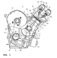
- Fig. 1 is a side view of an in-line multi-cylinder engine in a posture when mounted on a vehicle;
- Fig. 2 is a sectional view of a cam chain chamber of the in-line multi-cylinder engine;
- Fig. 3 is a side view of the cam chain chamber of the in-line multi-cylinder engine;
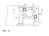
- Fig. 4 is a plan view of the mounting portion of a cam chain tensioner;
- Fig. 5 is a sectional view taken along the line V-V of Fig. 4;
- Fig. 6 is a sectional view showing an orifice in a lubricating oil passage.
- An engine for a vehicle 1 in this embodiment has a crankcase 2, a cylinder block 3 and a cylinder head 4.
- the crankcase 2 is comprised of a lower case 2a and an upper case 2b, an oil pan 5 is joined to the lower case 2a at the bottom, and a cylinder block 3 to the upper case 2b at the top.
- a plurality of cylinders 3a is disposed in the cylinder block 3 in series and the cylinder head 4 is joined to the cylinder block 3 at the top.
- a crankshaft 10 is supported on the mating surfaces of the lower case 2a and upper case 2b, as in known engines.
- Pistons 11 disposed in the plurality of cylinders 3a are connected to the crankshaft 10 through connecting rods 12.
- the cylinder 3a, the head of the piston 11 and the recess of the cylinder head 4 define a combustion chamber 13, and the cylinder head 4 is formed with an intake passage 14 and an exhaust passage 15 each open to the combustion chamber 13.
- the cylinder head 4 is provided with an intake valve 16 capable of opening/closing an opening 14a of the intake passage 14, and an exhaust valve 17 capable of opening/closing an opening 15a of the exhaust passage 15.
- the intake valve 16 and exhaust valve 17 are actuated for opening/closing by cams 18a, 19a on cam shafts 18, 19 disposed corresponding to the valves, respectively.
- the cylinder head 4 is covered by a head cover 30.
- the cam shafts 18, 19 are provided, at one ends, with sprockets 20, 21, respectively; a cam chain 23 is looped over the sprockets 20, 21 and a drive sprocket 22 provided on the crankshaft 10; the cam shafts 18, 19 rotate in association with the rotation of the crankshaft 10; and the intake valve 16 and exhaust valve 17 are opened/closed at given timings by the cams 18a, 19a on the cam shafts 18, 19.
- a cam chain chamber 31 for a cam chain 23 is disposed at the side of the crankcase 2, cylinder block 3 and cylinder head 4, and the cam chain chamber 31 is covered by a side cover 32.
- Power of the crankshaft 10 is transmitted to a transmission 41 through a clutch 40 and from the transmission 41 to a drive wheel through a power transmission mechanism.
- the transmission 41 is provided with an oil pump drive sprocket 42 and the oil pump drive sprocket 42 drives an oil pump 44 through an oil pump drive chain 43.
- the oil pump 44 is disposed at the side of the lower case 2a, as shown in Fig. 1, and has a suction port 44a and a delivery port 44b.
- a drawing pipe 45 disposed in the oil pan 5 is connected to the suction port 44a of the oil pump 44; a feed pipe 46 is connected to the delivery port 44b; the feed pipe 46 is connected to an oil cooler 47; and drive of the oil pump 44 draws up lubricating oil collected in the oil pan 5 and sends it to the oil cooler 47.
- Lubricating oil cooled by the oil cooler 47 is sent to bearings or the like of the crankshaft 10 through a lubricating oil passage 50 formed in the lower case 2a and further to lubricating portions of the pistons 11 and connecting rods 12 for lubrication. Further, lubricating oil is sent from the lubricating oil passage 51 to a lubricating oil passage 52 formed in the cylinder block 3 and from the lubricating oil passage 52 to a lubricating oil passage 53 formed in the cylinder head 4 and to bearings of the cam shafts 18, 19 through the lubricating oil passage 53, for lubrication.
- a gasket 54 is disposed between the cylinder block 3 and cylinder head 4, as shown in Fig. 6.
- the gasket 54 is formed with an orifice 55, and the orifice causes the passage between the lubricating oil passage 52 and lubricating oil passage 53 to be decreased in diameter into the form of a choke.
- Lubricating pressure of the lubricating oil passages 50, 51, 52 is prevented from being lowered on the upstream side of the orifice 55, and the bearings or the like of the crankshaft 10 and the lubricating portions of the pistons 11 and connecting rods 12 can be lubricated reliably.
- a cam chain tensioner 60 actuated by the pressure of lubricating oil for stabilizing the movement of the cam chain 23, lubricating oil passages 50, 51, 52, 53 through which lubricating oil is supplied to the cam shafts 18, 19 in the cylinder head 4, and a branched lubricating oil passage 56, branched from the lubricating oil passage 52, through which lubricating oil is supplied to the cam chain tensioner 60.
- Tensioner shoes 70, 71, 72 are in working contact with the cam chain 23.
- the tensioner shoe 70 is fixed to the head cover 30, the tensioner shoe 71 is fixed to the side cover 32, and the tensioner shoe 72 is provided on the side cover 32, for opening/closing movement, with a support shaft 73 as a pivot.
- the cam chain tensioner 60 has a plunger body 61 and a plunger 62, as shown in Fig. 4 and Fig. 5.
- the cylinder block 4 is formed with a mounting portion 4a projecting in the shape of a boss, and the mounting portion 4a is formed with a mounting hole 4a1.
- the plunger body 61 is formed, at its head 61a, with a flange 61a1, and at its stem 61b, with an annular recess 61b2, and an O-ring 63 is fitted in the annular recess 61b2.
- the stem 61b of the plunger body 61 is inserted in the mounting hole 4a1, the flange 61 a1 is brought into abutment against a tensioner-mounting seat face 4a5 of the mounting portion 4a, and the flange 61a1 is fastened fixedly to the mounting portion 4a with fastening bolts 90.
- the clearance between the plunger body 61 and mounting hole 4a1 is sealed with the O-ring 63.
- the plunger 62 is provided in the plunger body 61 for sliding movement and the plunger 62 and plunger body 61 define a lubricating oil chamber 64 for supplying pressure to the plunger 62.
- a circlip 65 is fitted on the plunger 62.
- a support body 66 is disposed in the lubricating oil chamber 64, and the support body 66 divides the lubricating oil chamber into a first lubricating oil chamber 64a and a second chamber 64b.
- a spring 67 is disposed, being compressed, between the support body 66 and plunger 62, biasing the plunger 62 in a direction for its forward end 62a to be in working contact with a receiving body 74 of the tensioner shoe 72, and the plunger 62 is formed with a delivery passage 62b.
- the plunger body 61 is formed with a recess 61 c facing an opening 56a of the branched lubricating oil passage 56, and an induction passage 61 d is formed extending from the recess 61c and in communication with the first chamber 64a.
- lubricating oil is supplied to the first chamber 64a through the branched lubricating oil passage 56 and induction passage 61d and from the first chamber 64a to the second chamber 64b.
- This lubricating oil supply causes a pressure rise in the second chamber 64b, so that the plunger body 61 moves forward and the forward end 62a of the plunger 62 pushes the receiving body 74 of the tensioner shoe 72, applying a thrust force to the tensioner shoe 72.
- the plunger 62 is pushed out by the force of the spring 67, and the plunger 62 received a force from the tensioner shoe 72 stabilizes the movement of the cam chain 23 by the damping effect of the second chamber 64b filled with oil.
- the pressure of the second chamber 64b exceeds a given value, lubricating oil is discharged from the delivery passage 62b of the plunger 62 to the cam chain chamber 31. In this way, the cam tensioner 60 can be actuated by the pressure of lubricating oil to stabilize the movement of the cam chain 23.
- an air vent passage 80 in communication with the highest position of the lubricating oil chamber 64 of the first chamber 64a is formed, being directed radially outwardly, in the stem 61b of the plunger body 61.
- the air vent passage 80 has an opening 80a to the outside of the stem 61b and in communication with the mounting hole (opening) 4a1 of the cam chain tensioner 60.
- the forward portion of the stem 61b of the plunger body 61 from the opening 80a of the air vent passage 80 is decreased in diameter to form a small clearance 81 between the stem and the wall of the mounting hole (opening) 4a1 and air is discharged from the opening 80a of the air vent passage 80 to the clearance 81.
- the mounting hole 4a1 opens to the cam chain chamber 31 for the cam chain 23, and the opening is formed, at its upper edge, with a chamfer 4f.
- the chamfer 4f is formed such that the stem 61b of the plunger body 61 is opened up to a region near the opening 80a of the air vent passage 80, and air passing out from the air vent passage 80 to the clearance 81 formed in the mounting hole 4a1 can be discharged reliably to the chain chamber 31.
- the highest position of the lubricating oil chamber for supplying pressure to the plunger 62 corresponds to the forward end 62a of the plunger 62, depending on the placement of the cam chain tensioner 60 in this embodiment, air mixed in the lubricating oil can be discharged to the chain chamber 31 through the delivery passage 62b.
- the second chamber 64b of the lubricating oil chamber 64 corresponds to the highest position, depending on the placement of the cam chain tensioner 60, an air vent passage is formed in communication with the second chamber 64b. Therefore, air vent of the lubricating oil chamber 64 can be performed irrespective of the mounting angle of the cam chain tensioner 60, a pressure drop of lubricating oil due to air can be prevented and a high pressure can be secured.
- the air vent passage 80 is in communication with the clearance 81 of the mounting hole 4a1, therefore machining of the air vent passage 80 in the plunger body 61 is simply required, facilitating machining of the air vent passage 80.
- An air vent passage may be machined in the plunger 62, depending on the mounting angle of the cam chain tensioner 60.
- the branched lubricating oil passage 56 in this embodiment is branched from the lubricating oil passage 52 at a portion on the upstream side of the orifice 55 in the lubricating oil passage 52 located upstream of the cylinder head 4, and in communication with the cam chain tensioner 60, as shown in Fig. 6, so that a pressure drop in the lubricating oil chamber 64 of the cam chain tensioner 60 due to the orifice 55 can be prevented, securing a high pressure. Therefore, the cam chain tensioner 60 can be actuated without need of size increase in the oil pump 44.
- the cam chain tensioner 60 is mounted to the mounting portion 4a of the cylinder block 3 and the cylinder block 3 is formed with the branched lubricating oil passage 56. Therefore, particularly when the engine is mounted on a vehicle such as a motorcycle, the layout without placing any restriction on other parts is possible compared with when the lubricating oil passage is provided in the cylinder head 4 or around the crankcase 2, and the branched lubricating oil passage 56 is formed by machining directly in the cylinder block 3, effecting cost reduction due to a decreased number of parts.
- the tensioner-mounting seat face 4a5 for the cam chain tensioner 60 is located in the direction away from the cam chain 23 with respect to the lubricating oil passage 52 to the cylinder head 4 when viewed in the direction of the cylinder axis, the cam chain tensioner 60 is mounted at an outwardly protruded position, and interference with the lubricating oil passage 52 is avoided, facilitating machining.
- the branched lubricating oil passage 56 is machined by a tool from the side of a mounting opening of the tensioner-mounting seat face 4a5, as shown in Fig. 5, and by using the mounting opening of the mounting hole 4a1 for the cam chain tensioner 60, and therefore a plug for the machine hole, or the like is not required.
- the opening 56a of the branched lubricating oil passage 56 is located in a region a given distance inward from the mounting opening of the tensioner-mounting seat face 4a5, therefore the cam tensioner 60 can be sealed with an O-ring or the like.
- the air vent passage 80 is formed by drilling of a small hole in the plunger body 61, this invention is not limited to that, and a screw hole may be formed, in which is fitted a screw, and a small clearance between the screw hole and the screw may be used as an air vent passage.
- This invention can be applied to an engine for a vehicle, in particular a motorcycle, with a cam chain tensioner actuated by the pressure of lubricating oil for stabilizing the tension of a cam chain.
- an engine for a vehicle comprising: a cam chain tensioner actuated by the pressure of lubricating oil for stabilizing the movement of a cam chain; a lubricating oil passage through which lubricating oil is supplied to cam shafts in a cylinder head; and a branched lubricating oil passage, branched from the lubricating oil passage, through which lubricating oil is supplied to the cam chain tensioner, in which the branched lubricating oil passage is branched from the lubricating oil passage at a portion on the upstream side of an orifice in the lubricating oil passage located upstream of the cylinder head, and in communication with the cam chain tensioner.
- an engine for a vehicle comprising: a cam chain tensioner actuated by the pressure of lubricating oil for stabilizing the movement of a cam chain; a lubricating oil passage through which lubricating oil is supplied to cam shafts in a cylinder head; and a branched lubricating oil passage, branched from the lubricating oil passage, through which lubricating oil is supplied to the cam chain tensioner, in which the cam tensioner has a plunger for applying thrust force to a tensioner shoe, a lubricating oil chamber for supplying pressure to the plunger, and an air vent passage in communication with the highest position of the lubricating oil chamber.
- the engine is provided with a cam chain tensioner 60 actuated by the pressure of lubricating oil for stabilizing the movement of a cam chain 23; lubricating oil passages 50-53 through which lubricating oil is supplied to cam shafts 18, 19 in a cylinder head 4; and a branched lubricating oil passage 56, branched from the lubricating oil passage 52, through which lubricating oil is supplied to the cam chain tensioner 60.
- the branched lubricating oil passage 56 is branched from the lubricating oil passage 52 at a portion on the upstream side of an orifice 55 in the lubricating oil passage 52 located upstream of the cylinder head 4, and in communication with the cam chain tensioner 60.
Landscapes
- Engineering & Computer Science (AREA)
- General Engineering & Computer Science (AREA)
- Mechanical Engineering (AREA)
- Devices For Conveying Motion By Means Of Endless Flexible Members (AREA)
- Lubrication Of Internal Combustion Engines (AREA)
- General Details Of Gearings (AREA)
- Lubrication Details And Ventilation Of Internal Combustion Engines (AREA)
Abstract
Description
- The invention relates to an engine for a vehicle, in particular a motorcycle, comprising a cam chain tensioner actuated by a pressure of lubricating oil for stabilizing the movement of a cam chain.
- Such an engine is known, e.g. from JP-A-2000-240743.
- Generally, in an engine for a vehicle for transmitting rotation of a crankshaft to cam shafts, a system has been known in which a cam chain tensioner using a plunger adapted to be pushed out by oil pressure, is provided to stabilize the movement of a cam chain.
- In some cam tenioners of this type, a passage through which lubricating oil is supplied to the cam tensioner, is provided with a delivery pipe separate from a crankcase and lubricating oil is supplied to the cam chain tensioner through the delivery pipe. In a system with piping such as a separate delivery pipe as described above, it is necessary that interference with other members is avoided, which places restrictions on the layout and increases the number of parts, causing increased manufacturing costs.
- In some systems, as the one of the above kind, the cam chain tensioner is mounted to a cylinder head and lubricating oil is supplied to the cam chain tensioner from a separate hydraulic control valve via a lubricating oil passage formed in the cylinder head. In this case, however, the pressure of lubricating oil is decreased because of the lubricating oil being supplied from the lubricating oil passage into the cylinder head on the downstream side, or the pressure of lubricating oil is decreased because of air mixed in the lubricating oil.
- Therefore, it is an object of the invention to provide an improved engine for a vehicle capable of effecting cost reduction and, thereby, securing a high pressure to a cam chain tensioner.
- For an engine of the above kind, this objective is solved in an inventive manner in that a branched lubricating oil passage through which lubricating oil is supplied to the cam chain tensioner is provided, which is branched from a lubricating oil passage through which lubricating oil is supplied to a cam shaft located in a cylinder head.
- By providing a branched lubricating oil passage from a lubricating passage for the camshaft, cost reduction is achieved due to layout placing, thereby having no restriction on other parts and a decreased number of parts. At the same time, high pressure for the cam chain tensioner can thereby be secured.
- Preferably, the branched lubricating oil passage is branched from a lubricating oil passage formed in a cylinder block of the engine.
- More preferably, the branched lubricating oil passage is branched from the lubricating oil passage at a portion on an upstream side of an orifice in the lubricating oil passage located upstream of the cylinder head, and in communication with the cam chain tensioner.
- Still more preferably, the orifice is formed by a gasket provided between the cylinder block and the cylinder head.
- According to a further preferred embodiment, the cam chain tensioner is mounted to a cylinder block and the cylinder block is formed with the branched lubricating oil passage.
- It is still further preferred that a tensioner-mounting seat face for the cam chain is located in the direction away from the cam chain with respect to the lubricating oil passage to the cylinder head when viewed in the direction of the cylinder axis.
- Therein, preferably the branched lubricating oil passage is machined from the side of a mounting opening of the tensioner-mounting seat face.
- It is possible that the branched lubricating oil passage opens to a region a given distance inward from the mounting opening of the tensioner-mounting seat face.
- Additionally or alternatively, it is preferred that the cam tensioner has a plunger for applying thrust force to a tensioner shoe, a lubricating oil chamber for supplying pressure to the plunger, and an air vent passage in communication with the highest position of the lubricating oil chamber.
- Therein, preferably the air vent passage is in communication with a mounting hole of the cam chain tensioner. More preferably the mounting hole opens to a cam chain chamber for the cam chain and the opening is chamfered at its upper edge.
- Since the branched lubricating oil passage through which oil pressure is supplied to the cam chain tensioner, is branched from a lubricating oil passage at a portion on the upstream side of an orifice in the lubricating oil passage located upstream of a cylinder head, a pressure drop caused by the orifice is prevented and a high pressure can be secured.
- Further, since the cylinder block is formed with a branched lubricating oil passage, particularly when the engine is mounted on a vehicle such as a motorcycle, the layout without placing any restriction on other parts is possible compared with when the lubricating oil passage is provided in the cylinder head or around the crankcase. Also, the lubricating oil passage may be formed by machining directly in the cylinder block. Therefore, cost reduction due to decreased number of parts can be effected additionally.
- Since, further the tensioner-mounting seat face for the cam chain tensioner is preferably located in the direction away from the cam chain with respect to the cylinder head, the cam chain tensioner is mounted at an outwardly protruded position and interface with the lubricating oil passage can be avoided, facilitating machining.
- Moreover, since the branched lubricating oil passage is machined from the side of a mounting opening of the tensioner-mounting seat face using the mounting opening, a plug for the machine hole, or the like is not required.
- As described above, it is preferred that the branched lubricating oil passage opens to a region a given distance inward from the mounting opening of the tensioner-mounting seat face. Therefore, the cam chain tensioner can be sealed with an O-ring or the like.
- Since, according to an embodiment, the cam chain tensioner has an air vent passage in communication with the highest position of the lubricating oil chamber for supplying pressure to the plunger, air vent of the lubricating oil chamber can be performed irrespective of the mounting angle of the cam chain tensioner, securing a high pressure.
- Further, since the air vent passage is in communication with the mounting hole of the cam chain tensioner, an air vent passage in the cam chain tensioner is simply required, facilitating machining of the air vent passage.
- Furthermore, since the mounting hole opens to the cam chain chamber for the cam chain and the opening is chamfered at its upper edge, air passing out from the mounting hole can be discharge reliably to the chain chamber.
- Further preferred embodiments are subject to the subclaims.
- In the following, the invention will be described in greater detail by means of an embodiment thereof with reference to the accompanying drawings, wherein:
- Fig. 1
- is a side view of an in-line multi-cylinder engine;
- Fig. 2
- is a sectional view of a cam chain chamber of the in-line multi-cylinder engine;
- Fig. 3
- is a side view of the cam chain chamber of the in-line multi-cylinder engine;
- Fig. 4
- is a plan view of the mounting portion of a cam chain tensioner;
- Fig. 5
- is a sectional view taken along the line V-V of Fig. 4; and
- Fig. 6
- is a sectional view showing an orifice in a lubricating oil passage.
- Although an embodiment of the engine for a vehicle of this invention will be described below with reference to the drawings, this invention is not limited to this embodiment. Also, the embodiment of this invention shows a best mode of the invention and technical terms of this invention are not limited to those used herein.
- Fig. 1 is a side view of an in-line multi-cylinder engine in a posture when mounted on a vehicle; Fig. 2 is a sectional view of a cam chain chamber of the in-line multi-cylinder engine; Fig. 3 is a side view of the cam chain chamber of the in-line multi-cylinder engine; Fig. 4 is a plan view of the mounting portion of a cam chain tensioner; Fig. 5 is a sectional view taken along the line V-V of Fig. 4; and Fig. 6 is a sectional view showing an orifice in a lubricating oil passage.
- An engine for a
vehicle 1 in this embodiment has acrankcase 2, acylinder block 3 and acylinder head 4. Thecrankcase 2 is comprised of alower case 2a and anupper case 2b, anoil pan 5 is joined to thelower case 2a at the bottom, and acylinder block 3 to theupper case 2b at the top. A plurality ofcylinders 3a is disposed in thecylinder block 3 in series and thecylinder head 4 is joined to thecylinder block 3 at the top. - A
crankshaft 10 is supported on the mating surfaces of thelower case 2a andupper case 2b, as in known engines. Pistons 11 disposed in the plurality ofcylinders 3a are connected to thecrankshaft 10 through connectingrods 12. Thecylinder 3a, the head of thepiston 11 and the recess of thecylinder head 4 define a combustion chamber 13, and thecylinder head 4 is formed with anintake passage 14 and anexhaust passage 15 each open to the combustion chamber 13. - The
cylinder head 4 is provided with anintake valve 16 capable of opening/closing anopening 14a of theintake passage 14, and anexhaust valve 17 capable of opening/closing an opening 15a of theexhaust passage 15. Theintake valve 16 andexhaust valve 17 are actuated for opening/closing bycams cam shafts cylinder head 4 is covered by ahead cover 30. - The
cam shafts sprockets cam chain 23 is looped over thesprockets drive sprocket 22 provided on thecrankshaft 10; thecam shafts crankshaft 10; and theintake valve 16 andexhaust valve 17 are opened/closed at given timings by thecams cam shafts - In the engine for a
vehicle 1 of this embodiment, as shown in Fig. 2 and Fig. 3, acam chain chamber 31 for acam chain 23 is disposed at the side of thecrankcase 2,cylinder block 3 andcylinder head 4, and thecam chain chamber 31 is covered by aside cover 32. - Power of the
crankshaft 10 is transmitted to atransmission 41 through a clutch 40 and from thetransmission 41 to a drive wheel through a power transmission mechanism. Thetransmission 41 is provided with an oilpump drive sprocket 42 and the oilpump drive sprocket 42 drives anoil pump 44 through an oilpump drive chain 43. Theoil pump 44 is disposed at the side of thelower case 2a, as shown in Fig. 1, and has asuction port 44a and adelivery port 44b. Adrawing pipe 45 disposed in theoil pan 5 is connected to thesuction port 44a of theoil pump 44; afeed pipe 46 is connected to thedelivery port 44b; thefeed pipe 46 is connected to anoil cooler 47; and drive of theoil pump 44 draws up lubricating oil collected in theoil pan 5 and sends it to theoil cooler 47. - Lubricating oil cooled by the
oil cooler 47 is sent to bearings or the like of thecrankshaft 10 through a lubricatingoil passage 50 formed in thelower case 2a and further to lubricating portions of thepistons 11 and connectingrods 12 for lubrication. Further, lubricating oil is sent from the lubricatingoil passage 51 to alubricating oil passage 52 formed in thecylinder block 3 and from the lubricatingoil passage 52 to alubricating oil passage 53 formed in thecylinder head 4 and to bearings of thecam shafts oil passage 53, for lubrication. - A
gasket 54 is disposed between thecylinder block 3 andcylinder head 4, as shown in Fig. 6. Thegasket 54 is formed with anorifice 55, and the orifice causes the passage between the lubricatingoil passage 52 andlubricating oil passage 53 to be decreased in diameter into the form of a choke. Lubricating pressure of the lubricatingoil passages orifice 55, and the bearings or the like of thecrankshaft 10 and the lubricating portions of thepistons 11 and connectingrods 12 can be lubricated reliably. - In this embodiment of the engine for a
vehicle 1, there are provided acam chain tensioner 60 actuated by the pressure of lubricating oil for stabilizing the movement of thecam chain 23, lubricatingoil passages cam shafts cylinder head 4, and a branchedlubricating oil passage 56, branched from the lubricatingoil passage 52, through which lubricating oil is supplied to thecam chain tensioner 60. - Tensioner shoes 70, 71, 72 are in working contact with the
cam chain 23. Thetensioner shoe 70 is fixed to thehead cover 30, thetensioner shoe 71 is fixed to theside cover 32, and thetensioner shoe 72 is provided on theside cover 32, for opening/closing movement, with asupport shaft 73 as a pivot. - The
cam chain tensioner 60 has aplunger body 61 and aplunger 62, as shown in Fig. 4 and Fig. 5. Thecylinder block 4 is formed with a mountingportion 4a projecting in the shape of a boss, and the mountingportion 4a is formed with a mounting hole 4a1. - The
plunger body 61 is formed, at itshead 61a, with a flange 61a1, and at itsstem 61b, with an annular recess 61b2, and an O-ring 63 is fitted in the annular recess 61b2. Thestem 61b of theplunger body 61 is inserted in the mounting hole 4a1, theflange 61 a1 is brought into abutment against a tensioner-mounting seat face 4a5 of the mountingportion 4a, and the flange 61a1 is fastened fixedly to the mountingportion 4a withfastening bolts 90. The clearance between theplunger body 61 and mounting hole 4a1 is sealed with the O-ring 63. - The
plunger 62 is provided in theplunger body 61 for sliding movement and theplunger 62 andplunger body 61 define a lubricatingoil chamber 64 for supplying pressure to theplunger 62. Acirclip 65 is fitted on theplunger 62. - A
support body 66 is disposed in the lubricatingoil chamber 64, and thesupport body 66 divides the lubricating oil chamber into a firstlubricating oil chamber 64a and asecond chamber 64b. Aspring 67 is disposed, being compressed, between thesupport body 66 andplunger 62, biasing theplunger 62 in a direction for itsforward end 62a to be in working contact with a receivingbody 74 of thetensioner shoe 72, and theplunger 62 is formed with adelivery passage 62b. - The
plunger body 61 is formed with arecess 61 c facing anopening 56a of the branched lubricatingoil passage 56, and aninduction passage 61 d is formed extending from therecess 61c and in communication with thefirst chamber 64a. - In the
cam chain tensioner 60 of this embodiment, lubricating oil is supplied to thefirst chamber 64a through the branched lubricatingoil passage 56 andinduction passage 61d and from thefirst chamber 64a to thesecond chamber 64b. - This lubricating oil supply causes a pressure rise in the
second chamber 64b, so that theplunger body 61 moves forward and theforward end 62a of theplunger 62 pushes the receivingbody 74 of thetensioner shoe 72, applying a thrust force to thetensioner shoe 72. - The
plunger 62 is pushed out by the force of thespring 67, and theplunger 62 received a force from thetensioner shoe 72 stabilizes the movement of thecam chain 23 by the damping effect of thesecond chamber 64b filled with oil. When the pressure of thesecond chamber 64b exceeds a given value, lubricating oil is discharged from thedelivery passage 62b of theplunger 62 to thecam chain chamber 31. In this way, thecam tensioner 60 can be actuated by the pressure of lubricating oil to stabilize the movement of thecam chain 23. - In the lubricating
oil chamber 64 for supplying pressure to theplunger 62, as shown in Fig. 3, anair vent passage 80 in communication with the highest position of the lubricatingoil chamber 64 of thefirst chamber 64a is formed, being directed radially outwardly, in thestem 61b of theplunger body 61. Theair vent passage 80 has an opening 80a to the outside of thestem 61b and in communication with the mounting hole (opening) 4a1 of thecam chain tensioner 60. - The forward portion of the
stem 61b of theplunger body 61 from the opening 80a of theair vent passage 80 is decreased in diameter to form asmall clearance 81 between the stem and the wall of the mounting hole (opening) 4a1 and air is discharged from the opening 80a of theair vent passage 80 to theclearance 81. - The mounting hole 4a1 opens to the
cam chain chamber 31 for thecam chain 23, and the opening is formed, at its upper edge, with achamfer 4f. Thechamfer 4f is formed such that thestem 61b of theplunger body 61 is opened up to a region near the opening 80a of theair vent passage 80, and air passing out from theair vent passage 80 to theclearance 81 formed in the mounting hole 4a1 can be discharged reliably to thechain chamber 31. - If the highest position of the lubricating oil chamber for supplying pressure to the
plunger 62 corresponds to theforward end 62a of theplunger 62, depending on the placement of thecam chain tensioner 60 in this embodiment, air mixed in the lubricating oil can be discharged to thechain chamber 31 through thedelivery passage 62b. - Even if the highest position of the lubricating oil chamber for supplying pressure to the
plunger 62 corresponds, not to theforward end 62a of theplunger 62, but to thefirst chamber 64a of the lubricatingoil chamber 64 for supplying pressure to theplunger 62, depending on the placement of thecam chain tensioner 60, because of theair vent passage 80 being provided in communication with thefirst chamber 64a at the highest position, when air mixed in the lubricating oil is collected in thefirst chamber 64a, the air flows through theair vent passage 80 into theclearance 81 of the mounting hole 4a1 and air passing out from theclearance 81 of the mounting hole 4a1 can be discharged reliably to thechain chamber 31 through thechamfer 4f at the upper edge of the opening. - Also, if the
second chamber 64b of the lubricatingoil chamber 64 corresponds to the highest position, depending on the placement of thecam chain tensioner 60, an air vent passage is formed in communication with thesecond chamber 64b. Therefore, air vent of the lubricatingoil chamber 64 can be performed irrespective of the mounting angle of thecam chain tensioner 60, a pressure drop of lubricating oil due to air can be prevented and a high pressure can be secured. - Also, the
air vent passage 80 is in communication with theclearance 81 of the mounting hole 4a1, therefore machining of theair vent passage 80 in theplunger body 61 is simply required, facilitating machining of theair vent passage 80. An air vent passage may be machined in theplunger 62, depending on the mounting angle of thecam chain tensioner 60. - The branched
lubricating oil passage 56 in this embodiment is branched from the lubricatingoil passage 52 at a portion on the upstream side of theorifice 55 in the lubricatingoil passage 52 located upstream of thecylinder head 4, and in communication with thecam chain tensioner 60, as shown in Fig. 6, so that a pressure drop in the lubricatingoil chamber 64 of thecam chain tensioner 60 due to theorifice 55 can be prevented, securing a high pressure. Therefore, thecam chain tensioner 60 can be actuated without need of size increase in theoil pump 44. - Also, the
cam chain tensioner 60 is mounted to the mountingportion 4a of thecylinder block 3 and thecylinder block 3 is formed with the branched lubricatingoil passage 56. Therefore, particularly when the engine is mounted on a vehicle such as a motorcycle, the layout without placing any restriction on other parts is possible compared with when the lubricating oil passage is provided in thecylinder head 4 or around thecrankcase 2, and the branched lubricatingoil passage 56 is formed by machining directly in thecylinder block 3, effecting cost reduction due to a decreased number of parts. - Also, as shown in Fig. 3, the tensioner-mounting seat face 4a5 for the
cam chain tensioner 60 is located in the direction away from thecam chain 23 with respect to the lubricatingoil passage 52 to thecylinder head 4 when viewed in the direction of the cylinder axis, thecam chain tensioner 60 is mounted at an outwardly protruded position, and interference with the lubricatingoil passage 52 is avoided, facilitating machining. - Also, the branched lubricating
oil passage 56 is machined by a tool from the side of a mounting opening of the tensioner-mounting seat face 4a5, as shown in Fig. 5, and by using the mounting opening of the mounting hole 4a1 for thecam chain tensioner 60, and therefore a plug for the machine hole, or the like is not required. In addition, theopening 56a of the branched lubricatingoil passage 56 is located in a region a given distance inward from the mounting opening of the tensioner-mounting seat face 4a5, therefore thecam tensioner 60 can be sealed with an O-ring or the like. - Although in this embodiment, the
air vent passage 80 is formed by drilling of a small hole in theplunger body 61, this invention is not limited to that, and a screw hole may be formed, in which is fitted a screw, and a small clearance between the screw hole and the screw may be used as an air vent passage. - This invention can be applied to an engine for a vehicle, in particular a motorcycle, with a cam chain tensioner actuated by the pressure of lubricating oil for stabilizing the tension of a cam chain.
- As described above, an engine for a vehicle is provided comprising: a cam chain tensioner actuated by the pressure of lubricating oil for stabilizing the movement of a cam chain; a lubricating oil passage through which lubricating oil is supplied to cam shafts in a cylinder head; and a branched lubricating oil passage, branched from the lubricating oil passage, through which lubricating oil is supplied to the cam chain tensioner, in which the branched lubricating oil passage is branched from the lubricating oil passage at a portion on the upstream side of an orifice in the lubricating oil passage located upstream of the cylinder head, and in communication with the cam chain tensioner.
- As further described above, additionally or alternatively an engine for a vehicle is provided comprising: a cam chain tensioner actuated by the pressure of lubricating oil for stabilizing the movement of a cam chain; a lubricating oil passage through which lubricating oil is supplied to cam shafts in a cylinder head; and a branched lubricating oil passage, branched from the lubricating oil passage, through which lubricating oil is supplied to the cam chain tensioner, in which the cam tensioner has a plunger for applying thrust force to a tensioner shoe, a lubricating oil chamber for supplying pressure to the plunger, and an air vent passage in communication with the highest position of the lubricating oil chamber.
- Moreover, as described above, in order to provide an engine for a vehicle capable of effecting cost reduction due to layout placing no restriction on other parts and a decreased number of parts, and of securing a high pressure to a cam chain tensioner, it is proposed that the engine is provided with a
cam chain tensioner 60 actuated by the pressure of lubricating oil for stabilizing the movement of acam chain 23; lubricating oil passages 50-53 through which lubricating oil is supplied tocam shafts cylinder head 4; and a branchedlubricating oil passage 56, branched from the lubricatingoil passage 52, through which lubricating oil is supplied to thecam chain tensioner 60. The branchedlubricating oil passage 56 is branched from the lubricatingoil passage 52 at a portion on the upstream side of anorifice 55 in the lubricatingoil passage 52 located upstream of thecylinder head 4, and in communication with thecam chain tensioner 60.
Claims (10)
- Engine for a vehicle, in particular a motorcycle, comprising:characterized in thata cam chain tensioner (60) actuated by a pressure of lubricating oil for stabilizing the movement of a cam chain (23);
a branched lubricating oil passage (56) through which lubricating oil is supplied to the cam chain tensioner (60) is provided, which is branched from a lubricating oil passage (50-53) through which lubricating oil is supplied to a cam shaft (18,19) located in a cylinder head (4). - Engine according to claim 1, characterized in that the branched lubricating oil passage (56) is branched from a lubricating oil passage (52) formed in a cylinder block (3) of the engine (1).
- Engine according to claim 1 or 2, characterized in that the branched lubricating oil passage (56) is branched from the lubricating oil passage (50-53) at a portion on an upstream side of an orifice (55) in the lubricating oil passage (50-53) located upstream of the cylinder head (4), and in communication with the cam chain tensioner (60).
- Engine according to claim 3, characterized in that the orifice (55) is formed by a gasket (54) provided between the cylinder block (3) and the cylinder head (4).
- Engine according to at least one of the claims 1 to 4, characterized in that the cam chain tensioner (60) is mounted to a cylinder block (3) and/or in that the cylinder block (3) is formed with the branched lubricating oil passage (56).
- Engine according to at least one of the claims 1 to 5, characterized in that a tensioner-mounting seat face (4a5) for the cam chain tensioner (60) is located in a direction away from the cam chain (23) with respect to the lubricating oil passage (50-53) to the cylinder head (4) when viewed in the direction of a cylinder axis.
- Engine according to at least one of the claims 1 to 6, characterized in that the branched lubricating oil passage (56) is machined from the side of a mounting opening (4a1) of a tensioner-mounting seat face (4a5) fro the cam chain tensioner (60).
- Engine according to at least one of the claims 1 to 7, characterized in that the branched lubricating oil passage (56) opens to a region which is a given distance inward from a mounting opening (4a1) of a tensioner-mounting seat face (4a5) for the cam chain tensioner (60).
- Engine according to at least one of the claims 1 to 8, characterized in that the cam tensioner (60) has a plunger (62) for applying thrust force to a tensioner shoe (70,71,72), a lubricating oil chamber (64) for supplying pressure to the plunger (62), and/or an air vent passage (80) in communication with the highest position of the lubricating oil chamber (64).
- Engine according to claim 9, characterized in that the air vent passage is in communication with a mounting opening (4a1) of the cam chain tensioner (60), wherein preferably the mounting opening (4a1) opens to a cam chain chamber (31) for the cam chain (23) and/or wherein the mounting opening (4a1) is chamfered at its upper edge (4f).
Applications Claiming Priority (2)
| Application Number | Priority Date | Filing Date | Title |
|---|---|---|---|
| JP2003290203A JP2005061274A (en) | 2003-08-08 | 2003-08-08 | Engine for vehicle |
| JP2003290203 | 2003-08-08 |
Publications (2)
| Publication Number | Publication Date |
|---|---|
| EP1505265A2 true EP1505265A2 (en) | 2005-02-09 |
| EP1505265A3 EP1505265A3 (en) | 2008-10-15 |
Family
ID=33550075
Family Applications (1)
| Application Number | Title | Priority Date | Filing Date |
|---|---|---|---|
| EP04018842A Ceased EP1505265A3 (en) | 2003-08-08 | 2004-08-09 | Engine for a vehicle |
Country Status (3)
| Country | Link |
|---|---|
| US (1) | US6973902B2 (en) |
| EP (1) | EP1505265A3 (en) |
| JP (1) | JP2005061274A (en) |
Cited By (2)
| Publication number | Priority date | Publication date | Assignee | Title |
|---|---|---|---|---|
| EP1950455A1 (en) * | 2007-01-18 | 2008-07-30 | HONDA MOTOR CO., Ltd. | Engine |
| FR2917464A1 (en) * | 2007-06-12 | 2008-12-19 | Peugeot Citroen Automobiles Sa | Internal combustion engine, has tensioning device with tensioning pad movable with respect to body and hydraulic piston to press tensioning pad on transmission chain, and cylinder head with housing forming body of tensioning device |
Families Citing this family (14)
| Publication number | Priority date | Publication date | Assignee | Title |
|---|---|---|---|---|
| CN100567708C (en) * | 2006-03-08 | 2009-12-09 | 无锡开普动力有限公司 | Lubricating structure of engine |
| US8522742B2 (en) * | 2009-01-30 | 2013-09-03 | Honda Motor Co., Ltd. | Multi-cylinder internal combustion engine |
| DE102010005827A1 (en) * | 2010-01-27 | 2011-07-28 | GM Global Technology Operations LLC, ( n. d. Ges. d. Staates Delaware ), Mich. | Oil supply |
| US8857320B2 (en) | 2011-10-28 | 2014-10-14 | Adco Industries-Technologies, L.P. | Roller grill |
| US8869683B2 (en) | 2011-10-28 | 2014-10-28 | ADCO Industries—Technologies, L.P. | Roller grill |
| US8857319B2 (en) | 2011-10-28 | 2014-10-14 | ADCO Industries—Technologies, L.P. | Roller grill |
| US8857321B2 (en) | 2011-10-28 | 2014-10-14 | ADCO Industries—Technologies, L.P. | Roller grill |
| US8857322B2 (en) | 2011-10-28 | 2014-10-14 | ADCO Industries—Technologies, L.P. | Roller grill |
| US9739186B2 (en) * | 2013-03-13 | 2017-08-22 | Cummins Ip, Inc. | Engine lubrication system |
| JP2014227924A (en) * | 2013-05-23 | 2014-12-08 | ヤマハ発動機株式会社 | Internal combustion engine and motorcycle having the same |
| US9545172B2 (en) | 2014-02-11 | 2017-01-17 | Adco Industries-Technologies, L.P. | Roller grill |
| JP6519427B2 (en) * | 2015-09-24 | 2019-05-29 | スズキ株式会社 | Vehicle drive system |
| JP6820118B2 (en) * | 2018-11-30 | 2021-01-27 | 本田技研工業株式会社 | Internal combustion engine |
| US11466755B2 (en) * | 2020-02-03 | 2022-10-11 | Borgwarner Inc. | Chain guide and tensioning apparatus for vehicles |
Citations (4)
| Publication number | Priority date | Publication date | Assignee | Title |
|---|---|---|---|---|
| US5333578A (en) | 1990-10-18 | 1994-08-02 | Honda Giken Kogyo Kabushiki Kaisha | Four-cycle engine |
| JP2000240743A (en) | 1999-02-22 | 2000-09-05 | Honda Motor Co Ltd | Oil passage structure of tensioner device |
| US6164257A (en) | 1998-09-30 | 2000-12-26 | Suzuki Motor Corporation | Oil passage construction for an engine with an oil pressure control device |
| US6325033B1 (en) | 1998-02-10 | 2001-12-04 | Honda Giken Kogyo Kabushiki Kaisha | Covering structure for covering timing mechanism and timing mechanism chamber structure inside cover comprised in covering structure for internal combustion engine |
Family Cites Families (6)
| Publication number | Priority date | Publication date | Assignee | Title |
|---|---|---|---|---|
| DE3543747A1 (en) * | 1984-12-11 | 1986-06-12 | Honda Giken Kogyo K.K., Tokio/Tokyo | CYLINDER BLOCK AND HEAD UNIT FOR AN INTERNAL COMBUSTION ENGINE |
| JP2503434Y2 (en) * | 1989-05-31 | 1996-07-03 | 日産自動車株式会社 | Engine chain tensioner device |
| DE4023728A1 (en) * | 1990-07-26 | 1992-01-30 | Porsche Ag | CHAIN TENSIONER FOR AN INTERNAL COMBUSTION ENGINE |
| JP2601539Y2 (en) * | 1993-10-15 | 1999-11-22 | 株式会社椿本チエイン | Tensioner with reservoir tank covered with flat or convex plate |
| JP2001073718A (en) * | 1999-09-03 | 2001-03-21 | Yamaha Motor Co Ltd | Valve system for engine |
| JP3435143B2 (en) * | 2001-03-09 | 2003-08-11 | 川崎重工業株式会社 | Overhead cam type V engine |
-
2003
- 2003-08-08 JP JP2003290203A patent/JP2005061274A/en active Pending
-
2004
- 2004-08-05 US US10/912,589 patent/US6973902B2/en active Active
- 2004-08-09 EP EP04018842A patent/EP1505265A3/en not_active Ceased
Patent Citations (4)
| Publication number | Priority date | Publication date | Assignee | Title |
|---|---|---|---|---|
| US5333578A (en) | 1990-10-18 | 1994-08-02 | Honda Giken Kogyo Kabushiki Kaisha | Four-cycle engine |
| US6325033B1 (en) | 1998-02-10 | 2001-12-04 | Honda Giken Kogyo Kabushiki Kaisha | Covering structure for covering timing mechanism and timing mechanism chamber structure inside cover comprised in covering structure for internal combustion engine |
| US6164257A (en) | 1998-09-30 | 2000-12-26 | Suzuki Motor Corporation | Oil passage construction for an engine with an oil pressure control device |
| JP2000240743A (en) | 1999-02-22 | 2000-09-05 | Honda Motor Co Ltd | Oil passage structure of tensioner device |
Cited By (3)
| Publication number | Priority date | Publication date | Assignee | Title |
|---|---|---|---|---|
| EP1950455A1 (en) * | 2007-01-18 | 2008-07-30 | HONDA MOTOR CO., Ltd. | Engine |
| US7882819B2 (en) | 2007-01-18 | 2011-02-08 | Honda Motor Co., Ltd. | Engine |
| FR2917464A1 (en) * | 2007-06-12 | 2008-12-19 | Peugeot Citroen Automobiles Sa | Internal combustion engine, has tensioning device with tensioning pad movable with respect to body and hydraulic piston to press tensioning pad on transmission chain, and cylinder head with housing forming body of tensioning device |
Also Published As
| Publication number | Publication date |
|---|---|
| EP1505265A3 (en) | 2008-10-15 |
| JP2005061274A (en) | 2005-03-10 |
| US6973902B2 (en) | 2005-12-13 |
| US20050045131A1 (en) | 2005-03-03 |
Similar Documents
| Publication | Publication Date | Title |
|---|---|---|
| EP1505265A2 (en) | Engine for a vehicle | |
| US6871620B2 (en) | Variable cam timing unit oil supply arrangement | |
| US6357407B2 (en) | Anti-rotation valve lifter guide apparatus | |
| US4883027A (en) | Valve operating system for internal combustion engines | |
| US6032629A (en) | Variable valve timing arrangement | |
| US6966290B2 (en) | Engine valve train device | |
| US7637236B2 (en) | Cylinder head for an overhead-cam internal combustion engine, engine incorporating same, and vehicle incorporating the engine | |
| US7966982B2 (en) | Fixation structure for valve system rotation shaft of internal combustion engine | |
| US7363904B2 (en) | Lubrication device of engine | |
| US6364797B1 (en) | Motorcycle transmission | |
| US6263844B1 (en) | Oil passage for internal combustion engine | |
| US20050109299A1 (en) | Valve timing adjusting apparatus | |
| US7878165B2 (en) | Engine valve operating system | |
| US9567881B2 (en) | Valvetrain assembly | |
| US7293756B2 (en) | Engine fastening structure | |
| US7021266B2 (en) | Engine lubricating device | |
| US20050061290A1 (en) | Engine lubrication system and pressure reducing valve for limiting overhead oil flow | |
| US7104241B2 (en) | Engine fastening structure | |
| JPH08177416A (en) | Camshaft for valve system in ohc engine | |
| JP3198689B2 (en) | Engine lubrication device | |
| JP3146535B2 (en) | Lubricating oil passage for 4-stroke engine | |
| JPH06146838A (en) | Lubricating device for engine | |
| JPH06330719A (en) | Lubricator of internal combustion engine | |
| JP2012021416A (en) | Chain case |
Legal Events
| Date | Code | Title | Description |
|---|---|---|---|
| PUAI | Public reference made under article 153(3) epc to a published international application that has entered the european phase |
Free format text: ORIGINAL CODE: 0009012 |
|
| AK | Designated contracting states |
Kind code of ref document: A2 Designated state(s): AT BE BG CH CY CZ DE DK EE ES FI FR GB GR HU IE IT LI LU MC NL PL PT RO SE SI SK TR |
|
| AX | Request for extension of the european patent |
Extension state: AL HR LT LV MK |
|
| PUAL | Search report despatched |
Free format text: ORIGINAL CODE: 0009013 |
|
| AK | Designated contracting states |
Kind code of ref document: A3 Designated state(s): AT BE BG CH CY CZ DE DK EE ES FI FR GB GR HU IE IT LI LU MC NL PL PT RO SE SI SK TR |
|
| AX | Request for extension of the european patent |
Extension state: AL HR LT LV MK |
|
| RIC1 | Information provided on ipc code assigned before grant |
Ipc: F16H 7/08 20060101ALI20080909BHEP Ipc: F01M 9/10 20060101ALI20080909BHEP Ipc: F01L 1/02 20060101AFI20041110BHEP |
|
| 17P | Request for examination filed |
Effective date: 20081104 |
|
| AKX | Designation fees paid |
Designated state(s): AT BE BG CH CY CZ DE DK EE ES FI FR GB GR HU IE IT LI LU MC NL PL PT RO SE SI SK TR |
|
| 17Q | First examination report despatched |
Effective date: 20100208 |
|
| STAA | Information on the status of an ep patent application or granted ep patent |
Free format text: STATUS: THE APPLICATION HAS BEEN REFUSED |
|
| 18R | Application refused |
Effective date: 20140604 |