EP1505254A2 - Gas turbine and associated cooling method - Google Patents
Gas turbine and associated cooling method Download PDFInfo
- Publication number
- EP1505254A2 EP1505254A2 EP04103627A EP04103627A EP1505254A2 EP 1505254 A2 EP1505254 A2 EP 1505254A2 EP 04103627 A EP04103627 A EP 04103627A EP 04103627 A EP04103627 A EP 04103627A EP 1505254 A2 EP1505254 A2 EP 1505254A2
- Authority
- EP
- European Patent Office
- Prior art keywords
- gas turbine
- steam
- cooling
- air
- cooling device
- Prior art date
- Legal status (The legal status is an assumption and is not a legal conclusion. Google has not performed a legal analysis and makes no representation as to the accuracy of the status listed.)
- Granted
Links
Images

Classifications
-
- F—MECHANICAL ENGINEERING; LIGHTING; HEATING; WEAPONS; BLASTING
- F01—MACHINES OR ENGINES IN GENERAL; ENGINE PLANTS IN GENERAL; STEAM ENGINES
- F01D—NON-POSITIVE DISPLACEMENT MACHINES OR ENGINES, e.g. STEAM TURBINES
- F01D5/00—Blades; Blade-carrying members; Heating, heat-insulating, cooling or antivibration means on the blades or the members
- F01D5/12—Blades
- F01D5/14—Form or construction
- F01D5/18—Hollow blades, i.e. blades with cooling or heating channels or cavities; Heating, heat-insulating or cooling means on blades
- F01D5/186—Film cooling
-
- F—MECHANICAL ENGINEERING; LIGHTING; HEATING; WEAPONS; BLASTING
- F05—INDEXING SCHEMES RELATING TO ENGINES OR PUMPS IN VARIOUS SUBCLASSES OF CLASSES F01-F04
- F05D—INDEXING SCHEME FOR ASPECTS RELATING TO NON-POSITIVE-DISPLACEMENT MACHINES OR ENGINES, GAS-TURBINES OR JET-PROPULSION PLANTS
- F05D2260/00—Function
- F05D2260/20—Heat transfer, e.g. cooling
- F05D2260/232—Heat transfer, e.g. cooling characterized by the cooling medium
- F05D2260/2322—Heat transfer, e.g. cooling characterized by the cooling medium steam
Definitions
- the present invention relates to a gas turbine, in particular in one Power plant.
- the invention also relates to an associated method for cooling the gas turbine.
- Steam is due to its higher heat capacity and its lower viscosity, in principle, a better cooling medium than air. Steam In addition to cooling air also reduces the specific compressor power through the elimination of the pressure losses of the cooling air and reduces the NOX emissions by a lower at the same turbine inlet temperature Combustion chamber temperature.
- the steam cooling can be designed as an open or closed system become.
- an open system eg film cooling of the blades
- the Steam after he has fulfilled his cooling task, added to the working gas and thus acts as an efficiency and efficiency enhancer on the gas turbine.
- the present invention as characterized in the claims deals with the problem, for a gas turbine initially mentioned kind to provide an improved embodiment, with which in particular a Higher performance and extended life of critical components can be achieved.
- the invention is based on the general idea, in a gas turbine, which with a conventional air cooling device for cooling parts of Gas turbine is formed by means of air, in addition a steam cooling device provide, which for cooling parts of the gas turbine by means of steam is trained.
- the cooling of a rotor and a stator of the gas turbine Conventionally carried out with air, while additionally a small amount of steam e.g. from entering the turbine to exiting the turbine along a Rotor shell flows parallel to the hot gas flow. Steam is due to his higher heat capacity and its lower viscosity in principle a better Cooling medium as air. Steam instead of cooling air also reduces the required Coolant volume by approx. 50%.
- the essential advantage of the invention is that the performance of the additionally with steam cooled gas turbine compared to the conventional one air-cooled gas turbine increases by about 2 to 5%. This results from the higher turbine inlet temperature, which leads to a higher power. It is also noteworthy that only a comparatively small, purposeful applied amount of steam is needed, in conjunction with the air cooling a to achieve intensive cooling of the gas turbine.
- the steam cooling device may be designed at least for cooling the inner inner lining and / or the inner outer lining of the combustion chamber and / or the guide vanes and / or hub-side covering elements of the vanes, and / or for a steam guide to do so is formed, that from the row of vanes along a rotor shell, a vapor film is formed.
- This steam film protects the rotor from contact with the hot gas flow and thus leads to an extended life of the critical components of the gas turbine.
- the Steam cooling device for cooling an upstream region of the Guide vanes and the air cooling device for cooling a downstream side Be formed portion of the vanes offers the advantage that the Guide vanes in the thermally more heavily loaded inflow area intensively with steam be cooled.
- the invention uses the knowledge that for cooling the thermally less heavily polluted outflow area the air cooling sufficient, whereby with comparatively little energy a sufficient Blade cooling is achieved. If the injected for cooling steam over Outlets again exits into the hot gas stream, he produced at the Outer skin of the respective vane a fine vapor layer, which over the guide vanes and this similar to the rotor shell described above Protects against direct contact with the hot gas stream and thus to Robustness of the gas turbine contributes.
- the steam required for the steam cooling device can advantageously from a Waste heat boiler are taken from a steam turbine, which with the Gas turbine is coupled.
- the steam cooling thus requires no additional Steam generator.
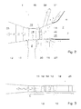
- a gas turbine 1 according to the invention comprises a combustion chamber 2 (burner not shown), a stator 5, a rotor 8 and a partially shown air cooling device 31 and also only partially shown steam cooling device 32nd
- the combustion chamber 2 is of a surrounded inner lining 3 and an inner outer lining 4.
- a hot gas stream 28 heated in the combustion chamber 2 strikes at least one row of guide vanes 6 with a plurality of guide vanes 7, which each have an inflow-side region 14 and an outflow-side region 15.
- a blade row 9 with a plurality of blades 10, which form part of the rotor 8.
- the steam cooling device 32 comprises a first cooling channel 24, which is arranged in the inner outer lining and, during operation of the steam cooling device 32, flows through vapor D.
- the first cooling channel 24 communicates at the end via an outer cover plate 29 with a third cooling channel 25, which is integrated in the guide blade 7.
- the third cooling channel 25 is arranged in the inflow-side region 14 of the guide vane 7 and has outlet openings 27, which communicate with the hot gas stream 28 on an outer side of the respective vane 7.
- the third cooling channel 27 communicates at the end with hub-side cover elements 11, so that the remaining, not exited through the outlet openings 27 steam D flows into the hub-side cover 11 and this also cools.
- outlet openings 27 ' are provided on the hub-side covering elements 11, from which the vapor D exits into the gas turbine 1 in the region of an inlet 21.
- the goal here is that most of the vapor D exits through the outlet openings 27 '.
- a second cooling channel 23 which is substantially parallel to the hot gas stream 28 in Direction of the vanes 7 runs.
- the second cooling channel 23 communicates at the end via outlet openings 27 ", which in the region of the hub side Covering elements 11 are arranged, with the hot gas stream 28 at the entrance of the Gas turbine 1.
- the steam D required for the steam cooling device 32 can advantageously not shown steam generators, in particular from a waste heat boiler, a Startup steam generator or a steam turbine can be removed, which with the gas turbine is coupled. An additional steam generator for the Steam cooling is therefore not required.
- the air cooling device 31 comprises a fourth cooling channel 26 of FIG is integrated into the guide vanes 7 in the downstream region 15.
- the cooling channel 26 is the input side with a cooling air source, not shown, beispw.
- the fourth Cooling channel 26 is traversed by air L and cooled by this.
- the blade row 9 Downstream of the guide vane row 6 is the blade row 9 with several Blades 10 arranged.
- the blades 10 are as in conventional Gas turbine 1 cooled with air L, which in the illustrated embodiment the rotor side flows into the blades 10.
- the air cooling device 31 is both according to the illustrated embodiment for cooling the blades 10 as well as downstream of the vanes. 7 arranged heat accumulation elements 19 is formed. The cooling of the Heat storage elements 19 takes place by cooling the hot gas stream 28 facing away from the heat accumulation elements 19. Additionally or alternatively can according to FIG. 1 air L immediately downstream of the blades 10 in the Gas turbine 1 are blown and thus cooling the furnishedstauicide 19 on the hot gas stream 28 side facing or cause and / or reinforce the rotor shell 12.
- the usual cooling medium of hot gas components in a gas turbine 1 is air L, which from an end or intermediate stage of a not shown Compressor is removed.
- Critical places are the inside Interior trim 3 and the inside 4 of the outer lining Combustion chamber 2, the first row of vanes 6, the first blade row. 9 and the turbine rotor 8.
- the invention proposes a combined cooling by means of steam D and Air L ahead.
- the preferably slightly superheated steam D of the steam cooling device 32 flows in designated cooling channels 23 of the inner lining 3 (Inner liner) and cooling channels 24 of the inner outer lining 4 (Outer liner) from the burner side.
- the inflowing steam D emerges from the end of the first cooling channel 24 and then is a Leitschaufelau jointplatte 29 in a followed by the third cooling channel 25 forwarded.
- the steam D flows into the hub-side cover plate 11 of the guide vane 7 and via outlet openings 27 'in the gas turbine 1.
- the steam D flows via outlet openings 27 in the upstream region 14 of the guide vanes 7 in The gas turbine 1.
- the goal here is that the majority of the steam D at the Hub exits.
- Another vapor stream D is fed to the inner liner 3 on the burner side and flows through cooling channels 23 of the inner liner 3 parallel to the hot gas stream 28th to the outlet opening 27 "in the region of the hub-side cover 11th
- the two vapor streams D of the inner liner 3 and the hub side Cover plate 11 form due to the higher density of the vapor D opposite the hot gas stream 28 during the expansion along the turbine 1 downstream of the Guide vanes 7 a steam curtain or film 13 of a certain current thickness along the rotor shell 12 or at the edge of the hot gas flow 28.
- This Steam film 13 protects the rotor 8 from contact with the hot gas stream 28 and leads thereby to an extended life of the critical components of Gas turbine 1.
- the inner lining 3 and the inner outer lining 4 are cooled with steam D.
- the steam required for this is approx. 50% of the amount of cooling air.
- the slightly overheated steam D required for cooling is preferably removed from a waste heat boiler, not shown. there can be provided that both the first cooling channel 24 and the second Cooling channel 23 from a common or separate waste heat boiler (s) can be fed.
- the power of the operated with the combined air or steam cooling Gas turbine 1 takes over the conventional air-cooled gas turbine about 2 to 5 percent, resulting in a combined gas turbine steam turbine plant
- the steam turbine power decreases due to the removal of the slightly superheated steam D from the waste heat boiler slightly, whereas the heat output of the waste heat boiler as a result of larger amount of gas turbine increases. Almost the largest part of this Performance is therefore due to the relaxation of the steam after cooling the inner lining 3,4 and the guide vanes 7 at a much higher Temperature and recovered at up to 1 bar in the gas turbine 1.
- the Saved cooling air amount of the guide vanes 7 flows through the combustion chamber. 2 and takes part in the combustion process, whereby an additional power of the Gas turbine 1 is achieved.
- the gas turbine 1 is shown in another embodiment, which is designed to carry out a sequential combustion.
- a high-pressure combustion chamber 2 'and a Hochdruckleitschaufelsch 22 are provided with a plurality of Hochdruckleitschaufeln 16 and at least one high-pressure blade row 17 with a plurality of high-pressure blades 18, which are followed downstream of a low-pressure combustion chamber and a low-pressure turbine, not shown.
- the high pressure blades 18 and the high pressure vanes 16 are cooled at least in their Anström Jardin with steam D, while the trailing edges of the high pressure vanes 16 can be cooled either also with steam or conventional with air.
- the design of the various cooling channels is designed so that a certain amount of steam flows through the high-pressure guide vanes 16 into the hub-side cover elements 11.
- a large part of the steam D then flows into the gas turbine 1 via outlet openings 27 'in a manner similar to that in FIG.
- the other part of the steam D flows into a gap 30, which is arranged below the rotor shell 12 and between the high pressure vanes 16 and the high pressure blades 18 to be sucked from there by the high pressure blades 18 for cooling.
- a portion of the steam D blocks the described gap 30 between Hochdruckleit- and high-pressure blades 16,18 with a certain amount of blown steam D.
- the remaining components are air-cooled.
- gas turbine 1 with sequential combustion produces the exited through the outlet openings 27 'vapor D a Steam film 13, which surrounds the rotor shell 12 and this before direct Contact with the hot gas stream 28 protects.
- Fig. 3 is a variant for cooling a High pressure compressor 20 shown.
- the invention provides, in a gas turbine 1, which with a conventional Air cooling device 31 for cooling parts of the gas turbine 1 by means of air is formed, in addition to provide a steam cooling device 32, which for Cooling of parts of the gas turbine 1 is formed by means of steam.
- the cooling of the rotor 8 and the stator 5 is conventional with air L executed.
- the advantages of the invention are that the performance of the additional with Steam D cooled gas turbine 1 compared to the conventional air-cooled Gas turbine 1, e.g. by about 2 to 5%, increases and at the same time due to the Steam films 13 a longer life of the critical components can be achieved can.
Abstract
Description
Die vorliegende Erfindung betrifft eine Gasturbine, insbesondere in einer Kraftwerksanlage. Die Erfindung betrifft außerdem ein zugehöriges Verfahren zum Kühlen der Gasturbine.The present invention relates to a gas turbine, in particular in one Power plant. The invention also relates to an associated method for cooling the gas turbine.
Ein Großteil der benötigten elektrischen Energie wird in Kraftwerken mit Hilfe von Dampf- und/oder Gasturbinen erzeugt. Der Wirkungsgrad dieser Anlagen ist entscheidend durch die Eintrittstemperatur des Arbeitsmediums (Gas oder Dampf) bestimmt. Sollen höhere Wirkungsgrade realisiert werden, so muss man zu höheren Temperaturen übergehen. Durch diese Temperaturerhöhungen wird jedoch sehr schnell die Grenze der Materialbeanspruchung erreicht. Deshalb ist zur Steigerung des Wirkungsgrades eine verstärkte Kühlung der Dampfund/oder Gasturbine erforderlich. Das übliche Kühlmedium der heißgasführenden Bauteile in einer Gasturbine ist Luft, entnommen aus der End- oder Zwischenstufe des Verdichters. Kritische Stellen sind dabei die Brennkammerauskleidung, die erste Leitschaufelreihe, die erste Laufschaufelreihe, der Turbinenrotor und der hintere Verdichterabschnitt. Generell ist aber auch eine Kühlung von Dampf- oder Gasturbinen mittels Dampf bekannt (DE 3003347). Dampf ist aufgrund seiner höheren Wärmekapazität und seiner kleineren Viskosität prinzipiell ein besseres Kühlmedium als Luft. Dampf anstelle von Kühlluft reduziert zudem die spezifische Verdichterleistung durch den Wegfall der Druckverluste der Kühlluft und vermindert die NOX-Emissionen durch eine bei gleicher Turbineneintrittstemperatur niedrigere Brennkammertemperatur.Much of the required electrical energy is used in power plants with the help of Steam and / or gas turbines generated. The efficiency of these systems is crucial by the inlet temperature of the working medium (gas or Steam). If higher efficiencies are to be realized, then one has to move to higher temperatures. Due to these temperature increases is However, very quickly reached the limit of material stress. Therefore To increase the efficiency of an increased cooling of the steam and / or Gas turbine required. The usual cooling medium of the hot gas Components in a gas turbine is air, taken from the end or Intermediate stage of the compressor. Critical places are the Combustion lining, the first row of vanes, the first Blade row, the turbine rotor and the rear compressor section. In general, however, is also a cooling of steam or gas turbines by means of steam known (DE 3003347). Steam is due to its higher heat capacity and its lower viscosity, in principle, a better cooling medium than air. steam In addition to cooling air also reduces the specific compressor power through the elimination of the pressure losses of the cooling air and reduces the NOX emissions by a lower at the same turbine inlet temperature Combustion chamber temperature.
Die Dampfkühlung kann als offenes oder als geschlossenes System ausgeführt werden. Bei einem offenen System (z. B. Filmkühlung der Schaufeln) wird der Dampf, nachdem er seine Kühlaufgabe erfüllt hat, dem Arbeitsgas zugemischt und wirkt dadurch leistungs- und wirkungsgradsteigernd auf die Gasturbine.The steam cooling can be designed as an open or closed system become. In an open system (eg film cooling of the blades) the Steam, after he has fulfilled his cooling task, added to the working gas and thus acts as an efficiency and efficiency enhancer on the gas turbine.
Die vorliegende Erfindung, wie sie in den Ansprüchen gekennzeichnet ist, beschäftigt sich mit dem Problem, für eine Gasturbine eingangs erwähnter Art eine verbesserte Ausführungsform anzugeben, mit welcher insbesondere eine höhere Leistung sowie eine verlängerte Lebensdauer der kritischen Bauteile erreicht werden kann.The present invention as characterized in the claims deals with the problem, for a gas turbine initially mentioned kind to provide an improved embodiment, with which in particular a Higher performance and extended life of critical components can be achieved.
Erfindungsgemäß wird dieses Problem durch die Gegenstände der unabhängigen Ansprüche gelöst. Vorteilhafte Ausführungsformen sind Gegenstand der abhängigen Ansprüche.According to the invention, this problem is solved by the objects of solved independent claims. Advantageous embodiments are Subject of the dependent claims.
Die Erfindung beruht auf dem allgemeinen Gedanken, bei einer Gasturbine, welche mit einer herkömmlichen Luftkühleinrichtung zur Kühlung von Teilen der Gasturbine mittels Luft ausgebildet ist, zusätzlich eine Dampfkühleinrichtung vorzusehen, welche zur Kühlung von Teilen der Gasturbine mittels Dampf ausgebildet ist. The invention is based on the general idea, in a gas turbine, which with a conventional air cooling device for cooling parts of Gas turbine is formed by means of air, in addition a steam cooling device provide, which for cooling parts of the gas turbine by means of steam is trained.
Beispielsweise wird die Kühlung eines Rotors und eines Stators der Gasturbine konventionell mit Luft ausgeführt, während zusätzlich eine kleine Dampfmenge z.B. vom Eintritt in die Turbine bis zum Austritt aus der Turbine entlang eines Rotormantels parallel zum Heißgasstrom strömt. Dampf ist aufgrund seiner höheren Wärmekapazität und seiner kleineren Viskosität prinzipiell ein besseres Kühlmedium als Luft. Dampf anstelle von Kühlluft reduziert zudem die benötigte Kühlmediummenge um ca. 50 %.For example, the cooling of a rotor and a stator of the gas turbine Conventionally carried out with air, while additionally a small amount of steam e.g. from entering the turbine to exiting the turbine along a Rotor shell flows parallel to the hot gas flow. Steam is due to his higher heat capacity and its lower viscosity in principle a better Cooling medium as air. Steam instead of cooling air also reduces the required Coolant volume by approx. 50%.
Der wesentliche Vorteil der Erfindung besteht darin, dass die Leistung der zusätzlich mit Dampf gekühlten Gasturbine gegenüber der konventionellen luftgekühlten Gasturbine um ca. 2 bis 5 % zunimmt. Dies resultiert aus der höheren Turbineneintrittstemperatur, welche zu einer höheren Leistung führt. Bemerkenswert ist außerdem, dass nur eine vergleichsweise kleine, gezielt applizierte Dampfmenge benötigt wird, um zusammen mit der Luftkühlung eine intensive Kühlung der Gasturbine zu erzielen.The essential advantage of the invention is that the performance of the additionally with steam cooled gas turbine compared to the conventional one air-cooled gas turbine increases by about 2 to 5%. This results from the higher turbine inlet temperature, which leads to a higher power. It is also noteworthy that only a comparatively small, purposeful applied amount of steam is needed, in conjunction with the air cooling a to achieve intensive cooling of the gas turbine.
Gemäß einer bevorzugten Ausführungsform der erfindungsgemäßen Lösung
kann vorgesehen sein, dass die Dampfkühleinrichtung zumindest zur Kühlung
der innenliegenden Innenverkleidung und/oder der innenliegenden
Außenverkleidung der Brennkammer und/oder der Leitschaufeln und/oder
nabenseitiger Abdeckelemente der Leitschaufeln ausgebildet ist, und/oder dass
eine Dampfführung so ausgebildet ist, dass ab der Leitschaufelreihe entlang
eines Rotormantels ein Dampffilm entsteht.
Dieser Dampffilm schützt den Rotor vor Kontakt mit dem Heißgasstrom und führt
dadurch zu einer verlängerten Lebensdauer der kritischen Bauteile der
Gasturbine.According to a preferred embodiment of the solution according to the invention, provision may be made for the steam cooling device to be designed at least for cooling the inner inner lining and / or the inner outer lining of the combustion chamber and / or the guide vanes and / or hub-side covering elements of the vanes, and / or for a steam guide to do so is formed, that from the row of vanes along a rotor shell, a vapor film is formed.
This steam film protects the rotor from contact with the hot gas flow and thus leads to an extended life of the critical components of the gas turbine.
Entsprechend einer bevorzugten Ausführungsform der Erfindung kann die Dampfkühleinrichtung zur Kühlung eines anströmseitigen Bereichs der Leitschaufeln und die Luftkühleinrichtung zur Kühlung eines abströmseitigen Bereichs der Leitschaufeln ausgebildet sein. Dies bietet den Vorteil, dass die Leitschaufeln im thermisch stärker belasteten Anströmbereich intensiv mit Dampf gekühlt werden. Die Erfindung nutzt dabei die Erkenntnis, dass zur Kühlung des thermisch weniger stark belasteten Abströmungsbereichs die Luftkühlung ausreicht, wodurch mit vergleichsweise wenig Energie eine hinreichende Schaufelkühlung erreicht wird. Sofern der zur Kühlung eingeblasene Dampf über Austrittsöffnungen wieder in den Heißgasstrom austritt, erzeugt er an der Außenhaut der jeweiligen Leitschaufel eine feine Dampfschicht, welche sich über die Leitschaufeln legt und diese ähnlich dem Rotormantel in oben beschriebener Weise vor direktem Kontakt mit dem Heißgasstrom schützt und damit zur Robustheit der Gasturbine beiträgt.According to a preferred embodiment of the invention, the Steam cooling device for cooling an upstream region of the Guide vanes and the air cooling device for cooling a downstream side Be formed portion of the vanes. This offers the advantage that the Guide vanes in the thermally more heavily loaded inflow area intensively with steam be cooled. The invention uses the knowledge that for cooling the thermally less heavily polluted outflow area the air cooling sufficient, whereby with comparatively little energy a sufficient Blade cooling is achieved. If the injected for cooling steam over Outlets again exits into the hot gas stream, he produced at the Outer skin of the respective vane a fine vapor layer, which over the guide vanes and this similar to the rotor shell described above Protects against direct contact with the hot gas stream and thus to Robustness of the gas turbine contributes.
Der für die Dampfkühleinrichtung benötigte Dampf kann vorteilhaft aus einem Abhitzekessel einer Dampfturbine entnommen werden, welche mit der Gasturbine gekoppelt ist. Die Dampfkühlung erfordert somit keinen zusätzlichen Dampferzeuger.The steam required for the steam cooling device can advantageously from a Waste heat boiler are taken from a steam turbine, which with the Gas turbine is coupled. The steam cooling thus requires no additional Steam generator.
Weitere wichtige Merkmale und Vorteile der vorliegenden Erfindung ergeben sich aus den Unteransprüchen, aus den Zeichnungen und aus der zugehörigen Figurenbeschreibung anhand der Zeichnungen.Other important features and advantages of the present invention will become apparent from the subclaims, from the drawings and from the associated Description of the figures with reference to the drawings.
Bevorzugte Ausführungsbeispiele der Erfindung sind in den Zeichnungen dargestellt und werden in der nachfolgenden Beschreibung näher erläutert, wobei sich gleiche Bezugszeichen auf gleiche oder ähnliche oder funktional gleiche Merkmale bezieht. Preferred embodiments of the invention are shown in the drawings and are explained in more detail in the following description, wherein the same reference numerals to the same or similar or functionally identical Features relates.
Es zeigen, jeweils schematisch
- Fig. 1
- einen Längsschnitt durch eine erfindungsgemäße Gasturbine,
- Fig. 2
- eine Darstellung wie in Fig. 1, jedoch bei einer anderen Ausführungsform,
- Fig. 3
- einen Längsschnitt durch einen Hochdruckverdichter.
- Fig. 1
- a longitudinal section through a gas turbine according to the invention,
- Fig. 2
- 4 shows a representation as in FIG. 1, but in another embodiment,
- Fig. 3
- a longitudinal section through a high pressure compressor.
Entsprechend Fig. 1 umfasst eine Gasturbine 1 nach der Erfindung eine
Brennkammer 2 (Brenner nicht dargestellt), einen Stator 5, einen Rotor 8 sowie
eine nur teilweise dargestellte Luftkühleinrichtung 31 und eine ebenfalls nur zum
Teil dargestellte Dampfkühleinrichtung 32. Die Brennkammer 2 wird von einer
innenliegenden Innenverkleidung 3 und einer innenliegenden Außenverkleidung
4 umgeben. In Strömungsrichtung nach der Brennkammer 2 trifft ein in der
Brennkammer 2 erhitzter Heißgasstrom 28 auf zumindest eine Leitschaufelreihe
6 mit mehreren Leitschaufeln 7, welche jeweils einen anströmseitigen Bereich 14
und einen abströmseitigen Bereich 15 aufweisen. Danach folgt eine
Laufschaufelreihe 9 mit mehreren Laufschaufeln 10, welche einen Teil des
Rotors 8 bilden.
Gemäß Fig. 1 umfasst die Dampfkühleinrichtung 32 einen ersten Kühlkanal 24,
der in der innenliegenden Außenverkleidung angeordnet und im Betrieb der
Dampfkühleinrichtung 32 von Dampf D durchströmt ist. Der erste Kühlkanal 24
kommuniziert endseitig über eine Außendeckplatte 29 mit einem dritten
Kühlkanal 25, welcher in die Leitschaufel 7 integriert ist. Der dritte Kühlkanal 25
ist im anströmseitigen Bereich 14 der Leitschaufel 7 angeordnet und weist
Austrittsöffnungen 27 auf, welche auf einer Außenseite der jeweiligen
Leitschaufel 7 mit dem Heißgasstrom 28 in Verbindung stehen. Der dritte
Kühlkanal 27 kommuniziert endseitig mit nabenseitigen Abdeckelementen 11, so
dass der restliche, nicht durch die Austrittsöffnungen 27 ausgetretene Dampf D in
die nabenseitigen Abdeckelemente 11 einströmt und diese ebenfalls kühlt.
Ähnlich den Austrittsöffnungen 27 am anströmseitigen Bereich 14 der
Leitschaufel 7 sind Austrittsöffnungen 27' an den nabenseitigen
Abdeckelementen 11 vorgesehen, aus welchen der Dampf D im Bereich eines
Eintritts 21 in die Gasturbine 1 austritt. Das Ziel ist hierbei, dass der größte Teil
des Dampfes D durch die Austrittsöffnungen 27' austritt.1, a
According to FIG. 1, the
Des weiteren ist in der innenliegenden Innenverkleidung 3 ein zweiter Kühlkanal
23 angeordnet, welcher im Wesentlichen parallel zum Heißgasstrom 28 in
Richtung der Leitschaufeln 7 verläuft. Der zweite Kühlkanal 23 kommuniziert
endseitig über Austrittsöffnungen 27", welche im Bereich der nabenseitigen
Abdeckelemente 11 angeordnet sind, mit dem Heißgasstrom 28 am Eingang der
Gasturbine 1.Furthermore, in the
Der für die Dampfkühleinrichtung 32 benötigte Dampf D kann vorteilhaft von nicht
dargestellten Dampfgeneratoren, insbesondere aus einem Abhitzekessel, einem
Startup-Dampferzeuger oder einer Dampfturbine entnommen werden, welche mit
der Gasturbine gekoppelt ist. Ein zusätzlicher Dampferzeuger für die
Dampfkühlung wird somit nicht benötigt.The steam D required for the
Gemäß Fig. 1 umfasst die Luftkühleinrichtung 31 einen vierten Kühlkanal 26 der
im abströmseitigen Bereich 15 in die Leitschaufeln 7 integriert ist. Der Kühlkanal
26 ist eingangsseitig mit einer nicht dargestellten Kühlluftquelle, beispw. einer
End- oder Zwischenstufe eines Verdichters, verbunden und kann ausgangsseitig
über Austrittsöffnungen 27''' mit dem Heißgasstrom 28 bzw. einem Inneren der
Gasturbine 1 kommunizieren. Im Unterschied zum ersten, zweiten und dritten
Kühlkanal 24,23,25 und den nabenseitigen Abdeckelementen 11, wird der vierte
Kühlkanal 26 von Luft L durchströmt und durch diese gekühlt.According to FIG. 1, the
Stromab der Leitschaufelreihe 6 ist die Laufschaufelreihe 9 mit mehreren
Laufschaufeln 10 angeordnet. Die Laufschaufeln 10 sind wie bei herkömmlichen
Gasturbinen 1 mit Luft L gekühlt, welche in der dargestellten Ausführungsform
rotorseitig in die Laufschaufeln 10 einströmt.Downstream of the
Die Luftkühleinrichtung 31 ist gemäß der dargestellten Ausführungsform sowohl
zur Kühlung der Laufschaufeln 10 als auch von stromab der Leitschaufeln 7
angeordneten Wärmestauelementen 19 ausgebildet. Die Kühlung der
Wärmestauelemente 19 erfolgt dabei durch eine Kühlung der dem Heißgasstrom
28 abgewandten Seite der Wärmestauelemente 19. Zusätzlich oder alternativ
kann gemäß Fig. 1 Luft L unmittelbar stromab der Laufschaufeln 10 in die
Gasturbine 1 eingeblasen werden und somit eine Kühlung der
Wärmestauelemente 19 auf der dem Heißgasstrom 28 zugewandten Seite bzw.
des Rotormantels 12 bewirken und/oder verstärken.The
Im Folgenden soll kurz die Funktionsweise der kombinierten Luft-/Dampfkühlung
der erfindungsgemäßen Gasturbine 1 erläutert werden:In the following is briefly the operation of the combined air / steam cooling
the
Das übliche Kühlmedium heißgasführender Bauteile in einer Gasturbine 1 ist Luft
L, welche aus einer End- oder Zwischenstufe eines nicht dargestellten
Verdichters entnommen wird. Kritische Stellen sind dabei die innenliegende
Innenverkleidung 3 und die innenliegende Aussenverkleidung 4 der
Brennkammer 2, die erste Leitschaufelreihe 6, die erste Laufschaufelreihe 9
sowie der Turbinenrotor 8. The usual cooling medium of hot gas components in a
Um die Turbinenleistung zu erhöhen und die Lebensdauer der Gasturbine 1 zu
verlängern, schlägt die Erfindung eine kombinierte Kühlung mittels Dampf D und
Luft L vor.To increase turbine performance and increase the life of the
Der vorzugsweise leicht überhitzte Dampf D der Dampfkühleinrichtung 32 strömt
in dafür vorgesehene Kühlkanäle 23 der innenliegenden Innenverkleidung 3
(Innenliner) und Kühlkanäle 24 der innenliegenden Außenverkleidung 4
(Außenliner) von der Brennerseite her ein.The preferably slightly superheated steam D of the
Der eingeströmte Dampf D tritt am Ende des ersten Kühlkanals 24 aus diesem
aus und wird anschließend über eine Leitschaufelaußendeckplatte 29 in einen
sich daran anschließenden dritten Kühlkanal 25 weitergeleitet. Nach der Kühlung
der Außendeckplatte 29 und des angeströmten Bereichs 14 der Leitschaufel 7
strömt der Dampf D in die nabenseitige Abdeckplatte 11 der Leitschaufel 7 und
über Austrittsöffnungen 27' in die Gasturbine 1. Gleichzeitig strömt der Dampf D
über Austrittsöffnungen 27 im anströmseitigen Bereich 14 der Leitschaufeln 7 in
die Gasturbine 1. Das Ziel ist hierbei, dass der größte Teil des Dampfes D an der
Nabe austritt.The inflowing steam D emerges from the end of the
Ein weiterer Dampfstrom D wird dem Innenliner 3 an der Brennerseite zugeführt
und strömt durch Kühlkanäle 23 des Innenliners 3 parallel zum Heißgasstrom 28
bis zur Austrittsöffnung 27" im Bereich der nabenseitigen Abdeckelemente 11.
Die beiden Dampfströme D des Innenliners 3 und der nabenseitigen
Abdeckplatte 11 bilden auf Grund der höheren Dichte des Dampfes D gegenüber
dem Heißgasstrom 28 bei der Entspannung entlang der Turbine 1 stromab der
Leitschaufeln 7 einen Dampfschleier bzw. -film 13 einer gewissen Stromdicke
entlang des Rotormantels 12 bzw. randseitig des Heißgasstroms 28. Dieser
Dampffilm 13 schützt den Rotor 8 vor Kontakt mit dem Heißgasstrom 28 und führt
dadurch zu einer verlängerten Lebensdauer der kritischen Bauteile der
Gasturbine 1.Another vapor stream D is fed to the
Die innenliegende Innenverkleidung 3 sowie die innenliegende Außenverkleidung
4 werden mit Dampf D gekühlt. Die hierfür benötigte Dampfmenge beträgt ca.
50 % der Kühlluftmenge. Der zur Kühlung benötigte leicht überhitzte Dampf D
wird vorzugsweise einem nicht dargestellten Abhitzekessel entnommenen. Dabei
kann vorgesehen sein, dass sowohl der erste Kühlkanal 24 als auch der zweite
Kühlkanal 23 aus einem gemeinsamen oder aus separaten Abhitzekessel(n)
gespeist werden können.The
Die Leistung der mit der kombinierten Luft- bzw. Dampfkühlung betriebenen
Gasturbine 1 nimmt gegenüber der konventionellen luftgekühlten Gasturbine um
ca. 2 bis 5 Prozent zu, was sich bei einer kombinierten Gasturbinen-Dampfturbinen-Anlage
wie folgt erklären lässt: Die Dampfturbinenleistung nimmt
infolge der Entnahme des leicht überhitzten Dampfes D aus dem Abhitzekessel
leicht ab, wohingegen die Wärmeleistung des Abhitzekessels in Folge der
größeren Menge aus der Gasturbine zunimmt. Fast der größte Teil dieser
Leistung wird deshalb infolge der Entspannung des Dampfes nach der Kühlung
der Innenverkleidung 3,4 und der Leitschaufeln 7 bei einer wesentlich höheren
Temperatur und bei bis zu 1 bar in der Gasturbine 1 zurückgewonnen. Die
eingesparte Kühlluftmenge der Leitschaufeln 7 strömt durch die Brennkammer 2
und nimmt am Verbrennungsprozess teil, wodurch eine Mehrleistung der
Gasturbine 1 erreicht wird.The power of the operated with the combined air or steam cooling
Entsprechend Fig. 2 ist die Gasturbine 1 in einer anderen Ausführungsform
dargestellt, welche zur Durchführung einer sequentiellen Verbrennung
ausgebildet ist. Hierzu sind zusätzlich eine Hochdruckbrennkammer 2' sowie
eine Hochdruckleitschaufelreihe 22 mit mehreren Hochdruckleitschaufeln 16 und
mindestens eine Hochdrucklaufschaufelreihe 17 mit mehreren
Hochdrucklaufschaufeln 18 vorgesehen, welche stromab von einer nicht
dargestellten Niederdruckbrennkammer und einer Niederdruckturbine gefolgt
werden.
Hierbei werden die Hochdrucklaufschaufeln 18 und die Hochdruckleitschaufeln
16 zumindest in ihrem Anströmbereich mit Dampf D gekühlt, während die
Hinterkanten der Hochdruckleitschaufeln 16 entweder ebenfalls mit Dampf oder
aber herkömmlich mit Luft gekühlt werden können. Die Konstruktion der
verschiedenen Kühlkanäle wird dabei so ausgestaltet, dass eine gewisse
Dampfmenge durch die Hochdruckleitschaufeln 16 in die nabenseitigen
Abdeckelemente 11 strömt. Ein großer Teil des Dampfes D strömt danach
ähnlich wie in Fig. 1 über Austrittsöffnungen 27' in die Gasturbine 1 ein. Der
andere Teil des Dampfes D strömt in einen Zwischenraum 30, welcher unterhalb
des Rotormantels 12 und zwischen den Hochdruckleitschaufeln 16 und den
Hochdrucklaufschaufeln 18 angeordnet ist, um von dort von den
Hochdrucklaufschaufeln 18 zur Kühlung angesaugt zu werden. Gleichzeitig sperrt
ein Teil des Dampfes D den beschriebenen Zwischenraum 30 zwischen
Hochdruckleit- und Hochdrucklaufschaufeln 16,18 mit einer gewissen Menge an
ausgeblasenem Dampf D. Die restlichen Bauteile werden luftgekühlt.2, the
Here, the
Auch bei der in Fig. 2 dargestellten Gasturbine 1 mit sequenzieller Verbrennung
erzeugt der durch die Austrittsöffnungen 27' ausgetretene Dampf D einen
Dampffilm 13, welcher sich um den Rotormantel 12 legt und diesen vor direktem
Kontakt mit dem Heißgasstrom 28 schützt.Also in the illustrated in Fig. 2
Gemäß Fig. 3 ist eine Ausführungsvariante zur Kühlung eines
Hochdruckverdichters 20 gezeigt. Hierbei sind geeignete Wärmestauelemente 19
zwischen den Hochdruckleitschaufeln 16 und den Hochdrucklaufschaufeln 18 am
Rotormantel 12 angeordnet und mit leicht überhitztem Dampf D, welcher am According to Fig. 3 is a variant for cooling a
Ende des Hochdruckverdichters 20 zugeführt und nach einer gewissen Strecke
am Ende des Hochdruckverdichters 20 wieder zurückgeführt wird, gekühlt.End of the
Zusammenfassend lassen sich die wesentlichen Merkmale der erfindungsgemäßen Lösung wie folgt charakterisieren:In summary, the essential features of inventive solution characterized as follows:
Die Erfindung sieht vor, bei einer Gasturbine 1, welche mit einer herkömmlichen
Luftkühleinrichtung 31 zur Kühlung von Teilen der Gasturbine 1 mittels Luft
ausgebildet ist, zusätzlich eine Dampfkühleinrichtung 32 vorzusehen, welche zur
Kühlung von Teilen der Gasturbine 1 mittels Dampf ausgebildet ist.The invention provides, in a
Die Kühlung des Rotors 8 und des Stators 5 wird konventionell mit Luft L
ausgeführt. Zusätzlich strömt nun eine kleine Dampfmenge vom Eintritt 21 in die
Gasturbine 1 bis zum Austritt aus der Gasturbine 1 entlang des Rotormantels 12
parallel zum Heißgasstrom 28. Auf Grund der höheren Dichte des Dampfes D
gegenüber dem Heißgasstrom 28 bleibt dadurch ein Dampffilm 13 am
Rotormantel 12 bestehen und schützt diesen vor direktem Kontakt mit dem
Heißgasstrom 28.The cooling of the
Die Vorteile der Erfindung bestehen darin, dass die Leistung der zusätzlich mit
Dampf D gekühlten Gasturbine 1 gegenüber der konventionellen luftgekühlten
Gasturbine 1, z.B. um ca. 2 bis 5 %, zunimmt und gleichzeitig aufgrund des
Dampffilms 13 eine höhere Lebensdauer der kritischen Bauteile erreicht werden
kann. The advantages of the invention are that the performance of the additional with
Steam D cooled
- 11
- Gasturbinegas turbine
- 22
- Brennkammercombustion chamber
- 33
- innenliegende Innenverkleidunginside lining
- 44
- innenliegende Außenverkleidunginternal outer panel
- 55
- Statorstator
- 66
- Leitschaufelreihevane row
- 77
- Leitschaufelvane
- 88th
- Rotorrotor
- 99
- LaufschaufelreiheBlade row
- 1010
- Laufschaufelblade
- 1111
- nabenseitige Abdeckelementehub-side cover elements
- 1212
- Rotormantelsrotor shell
- 1313
- Dampffilmvapor film
- 1414
- anströmseitiger Bereichon the upstream side
- 1515
- abströmseitiger Bereichdownstream area
- 1616
- HochdruckleitschaufelHochdruckleitschaufel
- 1717
- HochdrucklaufschaufelreiheHigh pressure blade row
- 1818
- HochdrucklaufschaufelHigh pressure blade
- 1919
- WärmestauelementeHeat storage elements
- 2020
- HochdruckverdichterHigh-pressure compressors
- 2121
- Eintrittentry
- 2222
- HochdruckleitschaufelreiheHochdruckleitschaufelreihe
- 2323
- zweiter Kühlkanal second cooling channel
- 2424
- erster Kühlkanalfirst cooling channel
- 2525
- dritter Kühlkanalthird cooling channel
- 2626
- vierter Kühlkanalfourth cooling channel
- 2727
- Austrittsöffnungoutlet opening
- 2828
- HeißgasstromHot gas stream
- 2929
- AußendeckplatteOuter cover plate
- 3030
- Zwischenraumgap
- 3131
- LuftkühleinrichtungAir cooling device
- 3232
- DampfkühleinrichtungSteam cooling device
- DD
- Dampfsteam
- LL
- Luftair
Claims (11)
dadurch gekennzeichnet,
characterized,
dadurch gekennzeichnet, dass die Luftkühleinrichtung (31) zumindest zur Kühlung der Laufschaufeln (10) und/oder von stromab der Leitschaufelreihe (6) angeordneten Wärmestauelementen (19) ausgebildet ist.Gas turbine according to claim 1 or 2,
characterized in that the air cooling device (31) is designed at least for cooling the rotor blades (10) and / or from downstream of the guide blade row (6) arranged heat accumulation elements (19).
dadurch gekennzeichnet, dass die Dampfkühleinrichtung (32) zur Kühlung der Leitschaufeln (7) in einem anströmseitigen Bereich (14) und die Luftkühleinrichtung (31) zur Kühlung der Leitschaufeln (7) in einem abströmseitigen Bereich (15) ausgebildet sind.Gas turbine according to one of claims 1 to 3,
characterized in that the steam cooling device (32) for cooling the guide vanes (7) in an upstream region (14) and the air cooling device (31) for cooling the guide vanes (7) in a downstream region (15) are formed.
dadurch gekennzeichnet,
characterized,
dadurch gekennzeichnet,
characterized,
dadurch gekennzeichnet, dass die Luftkühleinrichtung (31) zumindest zur Kühlung der innenliegenden Innenverkleidung (3) der Hochdruckbrennkammer (2') und/oder der innenliegenden Außenverkleidung (4) der Hochdruckbrennkammer (2') und/oder der Hinterkante der Hochdruckleitschaufeln (16) und/oder von stromab der Hochdruckleitschaufelreihe (22) angeordneten Wärmestauelementen (19) ausgebildet ist.Gas turbine according to claim 5 or 6,
characterized in that the air cooling device (31) at least for cooling the inner lining (3) of the high pressure combustion chamber (2 ') and / or the inner outer lining (4) of the high pressure combustion chamber (2') and / or the trailing edge of the Hochdruckleitschaufeln (16) and / or from the high pressure vane row (22) arranged heat accumulation elements (19) is formed.
dadurch gekennzeichnet, dass die Dampfkühleinrichtung (32) zumindest zur teilweisen Kühlung eines Hochdruckverdichters (20) ausgebildet ist.Gas turbine according to one of claims 5 to 7,
characterized in that the steam cooling device (32) is designed at least for partial cooling of a high-pressure compressor (20).
dadurch gekennzeichnet, dass die Dampfkühleinrichtung (32) zur Entnahme von Dampf (D) mit einem Abhitzekessel einer Dampfturbine verbunden ist, die mit der Gasturbine (1) gekoppelt ist.Gas turbine according to one of claims 5 to 8,
characterized in that the steam cooling device (32) for removing steam (D) is connected to a waste heat boiler of a steam turbine, which is coupled to the gas turbine (1).
gekennzeichnet durch,
die kennzeichnenden Merkmale wenigstens eines der Ansprüche 2 bis 9.Method according to claim 10,
characterized by
the characterizing features of at least one of claims 2 to 9.
Applications Claiming Priority (2)
| Application Number | Priority Date | Filing Date | Title |
|---|---|---|---|
| DE10336432A DE10336432A1 (en) | 2003-08-08 | 2003-08-08 | Gas turbine and associated cooling process |
| DE10336432 | 2003-08-08 |
Publications (3)
| Publication Number | Publication Date |
|---|---|
| EP1505254A2 true EP1505254A2 (en) | 2005-02-09 |
| EP1505254A3 EP1505254A3 (en) | 2012-07-04 |
| EP1505254B1 EP1505254B1 (en) | 2017-01-25 |
Family
ID=33547152
Family Applications (1)
| Application Number | Title | Priority Date | Filing Date |
|---|---|---|---|
| EP04103627.8A Not-in-force EP1505254B1 (en) | 2003-08-08 | 2004-07-28 | Gas turbine and associated cooling method |
Country Status (4)
| Country | Link |
|---|---|
| US (1) | US7040097B2 (en) |
| EP (1) | EP1505254B1 (en) |
| CN (1) | CN100507237C (en) |
| DE (1) | DE10336432A1 (en) |
Cited By (4)
| Publication number | Priority date | Publication date | Assignee | Title |
|---|---|---|---|---|
| EP1921270A3 (en) * | 2006-11-10 | 2010-11-03 | General Electric Company | Compound nozzle cooled engine |
| US7870742B2 (en) | 2006-11-10 | 2011-01-18 | General Electric Company | Interstage cooled turbine engine |
| US7926289B2 (en) | 2006-11-10 | 2011-04-19 | General Electric Company | Dual interstage cooled engine |
| US8783044B2 (en) | 2007-12-29 | 2014-07-22 | Alstom Technology Ltd | Turbine stator nozzle cooling structure |
Families Citing this family (19)
| Publication number | Priority date | Publication date | Assignee | Title |
|---|---|---|---|---|
| DE102005060704A1 (en) * | 2005-12-19 | 2007-06-28 | Rolls-Royce Deutschland Ltd & Co Kg | Gas turbine combustor |
| US7967568B2 (en) * | 2007-09-21 | 2011-06-28 | Siemens Energy, Inc. | Gas turbine component with reduced cooling air requirement |
| US8079804B2 (en) * | 2008-09-18 | 2011-12-20 | Siemens Energy, Inc. | Cooling structure for outer surface of a gas turbine case |
| CN101798959A (en) * | 2010-02-10 | 2010-08-11 | 马鞍山科达洁能有限公司 | Gas turbine |
| DE102010009477A1 (en) * | 2010-02-26 | 2011-09-01 | Rolls-Royce Deutschland Ltd & Co Kg | Aircraft gas turbine engine |
| CH703105A1 (en) * | 2010-05-05 | 2011-11-15 | Alstom Technology Ltd | Gas turbine with a secondary combustion chamber. |
| RU2543101C2 (en) | 2010-11-29 | 2015-02-27 | Альстом Текнолоджи Лтд | Axial gas turbine |
| US20120186261A1 (en) * | 2011-01-20 | 2012-07-26 | General Electric Company | System and method for a gas turbine exhaust diffuser |
| CN102278813A (en) * | 2011-09-13 | 2011-12-14 | 牟敦善 | Tandem type electric heater hot water tank and warm water tank |
| US8894359B2 (en) | 2011-12-08 | 2014-11-25 | Siemens Aktiengesellschaft | Gas turbine engine with outer case ambient external cooling system |
| US10094285B2 (en) | 2011-12-08 | 2018-10-09 | Siemens Aktiengesellschaft | Gas turbine outer case active ambient cooling including air exhaust into sub-ambient cavity |
| AU2013219140B2 (en) | 2012-08-24 | 2015-10-08 | Ansaldo Energia Switzerland AG | Method for mixing a dilution air in a sequential combustion system of a gas turbine |
| US10107498B2 (en) | 2014-12-11 | 2018-10-23 | General Electric Company | Injection systems for fuel and gas |
| US10094571B2 (en) | 2014-12-11 | 2018-10-09 | General Electric Company | Injector apparatus with reheat combustor and turbomachine |
| US10094569B2 (en) | 2014-12-11 | 2018-10-09 | General Electric Company | Injecting apparatus with reheat combustor and turbomachine |
| US10094570B2 (en) | 2014-12-11 | 2018-10-09 | General Electric Company | Injector apparatus and reheat combustor |
| US10883387B2 (en) * | 2016-03-07 | 2021-01-05 | General Electric Company | Gas turbine exhaust diffuser with air injection |
| US10669887B2 (en) * | 2018-02-15 | 2020-06-02 | Raytheon Technologies Corporation | Vane airfoil cooling air communication |
| US11686210B2 (en) | 2021-03-24 | 2023-06-27 | General Electric Company | Component assembly for variable airfoil systems |
Citations (2)
| Publication number | Priority date | Publication date | Assignee | Title |
|---|---|---|---|---|
| EP0911489A1 (en) | 1997-05-01 | 1999-04-28 | Mitsubishi Heavy Industries, Ltd. | Gas turbine cooling stationary blade |
| EP0955449A1 (en) | 1998-03-12 | 1999-11-10 | Mitsubishi Heavy Industries, Ltd. | Gas turbine blade |
Family Cites Families (8)
| Publication number | Priority date | Publication date | Assignee | Title |
|---|---|---|---|---|
| US4571935A (en) * | 1978-10-26 | 1986-02-25 | Rice Ivan G | Process for steam cooling a power turbine |
| US4314442A (en) * | 1978-10-26 | 1982-02-09 | Rice Ivan G | Steam-cooled blading with steam thermal barrier for reheat gas turbine combined with steam turbine |
| DE3003347A1 (en) * | 1979-12-20 | 1981-06-25 | BBC AG Brown, Boveri & Cie., Baden, Aargau | COOLED WALL |
| US4413477A (en) * | 1980-12-29 | 1983-11-08 | General Electric Company | Liner assembly for gas turbine combustor |
| US4565490A (en) * | 1981-06-17 | 1986-01-21 | Rice Ivan G | Integrated gas/steam nozzle |
| JP3142850B2 (en) * | 1989-03-13 | 2001-03-07 | 株式会社東芝 | Turbine cooling blades and combined power plants |
| US5340274A (en) * | 1991-11-19 | 1994-08-23 | General Electric Company | Integrated steam/air cooling system for gas turbines |
| US5253976A (en) * | 1991-11-19 | 1993-10-19 | General Electric Company | Integrated steam and air cooling for combined cycle gas turbines |
-
2003
- 2003-08-08 DE DE10336432A patent/DE10336432A1/en not_active Withdrawn
-
2004
- 2004-07-28 EP EP04103627.8A patent/EP1505254B1/en not_active Not-in-force
- 2004-08-06 US US10/912,119 patent/US7040097B2/en active Active
- 2004-08-09 CN CNB2004100565554A patent/CN100507237C/en not_active Expired - Fee Related
Patent Citations (2)
| Publication number | Priority date | Publication date | Assignee | Title |
|---|---|---|---|---|
| EP0911489A1 (en) | 1997-05-01 | 1999-04-28 | Mitsubishi Heavy Industries, Ltd. | Gas turbine cooling stationary blade |
| EP0955449A1 (en) | 1998-03-12 | 1999-11-10 | Mitsubishi Heavy Industries, Ltd. | Gas turbine blade |
Cited By (5)
| Publication number | Priority date | Publication date | Assignee | Title |
|---|---|---|---|---|
| EP1921270A3 (en) * | 2006-11-10 | 2010-11-03 | General Electric Company | Compound nozzle cooled engine |
| US7870742B2 (en) | 2006-11-10 | 2011-01-18 | General Electric Company | Interstage cooled turbine engine |
| US7870743B2 (en) | 2006-11-10 | 2011-01-18 | General Electric Company | Compound nozzle cooled engine |
| US7926289B2 (en) | 2006-11-10 | 2011-04-19 | General Electric Company | Dual interstage cooled engine |
| US8783044B2 (en) | 2007-12-29 | 2014-07-22 | Alstom Technology Ltd | Turbine stator nozzle cooling structure |
Also Published As
| Publication number | Publication date |
|---|---|
| EP1505254B1 (en) | 2017-01-25 |
| US7040097B2 (en) | 2006-05-09 |
| EP1505254A3 (en) | 2012-07-04 |
| US20050172634A1 (en) | 2005-08-11 |
| DE10336432A1 (en) | 2005-03-10 |
| CN100507237C (en) | 2009-07-01 |
| CN1580520A (en) | 2005-02-16 |
Similar Documents
| Publication | Publication Date | Title |
|---|---|---|
| EP1505254B1 (en) | Gas turbine and associated cooling method | |
| DE2320581C2 (en) | Gas turbine with air-cooled turbine blades | |
| DE60118848T2 (en) | Tandem cooling for a turbine blade | |
| DE2913548C2 (en) | Shaft cooling for a gas turbine engine | |
| DE60018817T2 (en) | Chilled gas turbine blade | |
| DE602004000527T2 (en) | Method for cooling hot turbine components by means of a partially cooled in an external heat exchanger air flow and so cooled turbine engine | |
| DE60132405T2 (en) | Cooling of turbine blades by specific blade distribution | |
| DE602004006942T2 (en) | Triple turbine cooling circuit | |
| DE602005000350T2 (en) | Turbine stator blade with improved cooling | |
| EP3059433B1 (en) | Gas turbine engine with oil cooler in the engine cladding | |
| EP1162355B1 (en) | Cooling method for a gas turbine and corresponding gas turbine | |
| EP2179143B1 (en) | Gap cooling between combustion chamber wall and turbine wall of a gas turbine installation | |
| WO2002090741A1 (en) | Method for cooling a gas turbine and gas turbine installation | |
| DE102009044585A1 (en) | A method, apparatus, and systems for circumferentially aligning turbine blades with respect to combustor tubes and cooling airflow through the turbine hot gas flowpath | |
| DE2147537A1 (en) | Cooling device for the ends of turbine blades with air expansion | |
| DE102008002890A1 (en) | Alternately cooled turbine stator | |
| DE102011055375A1 (en) | Turbomachine vane and method for cooling a turbomachinery vane | |
| DE60319486T2 (en) | Cooled vanes in a gas turbine | |
| DE102010037862A1 (en) | Whirl chambers for slit flow control | |
| EP1245806B1 (en) | Cooled gas turbine balde | |
| EP1656497A1 (en) | Diffuser located between a compressor and a combustion chamber of a gasturbine | |
| EP2084368A1 (en) | Turbine blade | |
| EP0928364A1 (en) | Method of compensating pressure loss in a cooling air guide system in a gas turbine plant | |
| DE10392802B4 (en) | steam turbine | |
| WO2005090755A1 (en) | Gas turbine with a compressor housing which is protected against cooling down and method for operating a gas turbine |
Legal Events
| Date | Code | Title | Description |
|---|---|---|---|
| PUAI | Public reference made under article 153(3) epc to a published international application that has entered the european phase |
Free format text: ORIGINAL CODE: 0009012 |
|
| AK | Designated contracting states |
Kind code of ref document: A2 Designated state(s): AT BE BG CH CY CZ DE DK EE ES FI FR GB GR HU IE IT LI LU MC NL PL PT RO SE SI SK TR |
|
| AX | Request for extension of the european patent |
Extension state: AL HR LT LV MK |
|
| PUAL | Search report despatched |
Free format text: ORIGINAL CODE: 0009013 |
|
| AK | Designated contracting states |
Kind code of ref document: A3 Designated state(s): AT BE BG CH CY CZ DE DK EE ES FI FR GB GR HU IE IT LI LU MC NL PL PT RO SE SI SK TR |
|
| AX | Request for extension of the european patent |
Extension state: AL HR LT LV MK |
|
| RIC1 | Information provided on ipc code assigned before grant |
Ipc: F01D 5/18 20060101AFI20120530BHEP |
|
| 17P | Request for examination filed |
Effective date: 20121210 |
|
| 17Q | First examination report despatched |
Effective date: 20130121 |
|
| AKX | Designation fees paid |
Designated state(s): AT BE BG CH CY CZ DE DK EE ES FI FR GB GR HU IE IT LI LU MC NL PL PT RO SE SI SK TR |
|
| RAP1 | Party data changed (applicant data changed or rights of an application transferred) |
Owner name: GENERAL ELECTRIC TECHNOLOGY GMBH |
|
| GRAP | Despatch of communication of intention to grant a patent |
Free format text: ORIGINAL CODE: EPIDOSNIGR1 |
|
| INTG | Intention to grant announced |
Effective date: 20160902 |
|
| GRAS | Grant fee paid |
Free format text: ORIGINAL CODE: EPIDOSNIGR3 |
|
| GRAA | (expected) grant |
Free format text: ORIGINAL CODE: 0009210 |
|
| STAA | Information on the status of an ep patent application or granted ep patent |
Free format text: STATUS: THE PATENT HAS BEEN GRANTED |
|
| AK | Designated contracting states |
Kind code of ref document: B1 Designated state(s): AT BE BG CH CY CZ DE DK EE ES FI FR GB GR HU IE IT LI LU MC NL PL PT RO SE SI SK TR |
|
| REG | Reference to a national code |
Ref country code: GB Ref legal event code: FG4D Free format text: NOT ENGLISH |
|
| REG | Reference to a national code |
Ref country code: CH Ref legal event code: EP |
|
| REG | Reference to a national code |
Ref country code: AT Ref legal event code: REF Ref document number: 864280 Country of ref document: AT Kind code of ref document: T Effective date: 20170215 |
|
| REG | Reference to a national code |
Ref country code: IE Ref legal event code: FG4D Free format text: LANGUAGE OF EP DOCUMENT: GERMAN |
|
| REG | Reference to a national code |
Ref country code: DE Ref legal event code: R096 Ref document number: 502004015449 Country of ref document: DE |
|
| RAP2 | Party data changed (patent owner data changed or rights of a patent transferred) |
Owner name: ANSALDO ENERGIA SWITZERLAND AG |
|
| REG | Reference to a national code |
Ref country code: NL Ref legal event code: MP Effective date: 20170125 |
|
| PG25 | Lapsed in a contracting state [announced via postgrant information from national office to epo] |
Ref country code: NL Free format text: LAPSE BECAUSE OF FAILURE TO SUBMIT A TRANSLATION OF THE DESCRIPTION OR TO PAY THE FEE WITHIN THE PRESCRIBED TIME-LIMIT Effective date: 20170125 |
|
| PG25 | Lapsed in a contracting state [announced via postgrant information from national office to epo] |
Ref country code: FI Free format text: LAPSE BECAUSE OF FAILURE TO SUBMIT A TRANSLATION OF THE DESCRIPTION OR TO PAY THE FEE WITHIN THE PRESCRIBED TIME-LIMIT Effective date: 20170125 Ref country code: GR Free format text: LAPSE BECAUSE OF FAILURE TO SUBMIT A TRANSLATION OF THE DESCRIPTION OR TO PAY THE FEE WITHIN THE PRESCRIBED TIME-LIMIT Effective date: 20170426 |
|
| PG25 | Lapsed in a contracting state [announced via postgrant information from national office to epo] |
Ref country code: ES Free format text: LAPSE BECAUSE OF FAILURE TO SUBMIT A TRANSLATION OF THE DESCRIPTION OR TO PAY THE FEE WITHIN THE PRESCRIBED TIME-LIMIT Effective date: 20170125 Ref country code: PT Free format text: LAPSE BECAUSE OF FAILURE TO SUBMIT A TRANSLATION OF THE DESCRIPTION OR TO PAY THE FEE WITHIN THE PRESCRIBED TIME-LIMIT Effective date: 20170525 Ref country code: SE Free format text: LAPSE BECAUSE OF FAILURE TO SUBMIT A TRANSLATION OF THE DESCRIPTION OR TO PAY THE FEE WITHIN THE PRESCRIBED TIME-LIMIT Effective date: 20170125 Ref country code: PL Free format text: LAPSE BECAUSE OF FAILURE TO SUBMIT A TRANSLATION OF THE DESCRIPTION OR TO PAY THE FEE WITHIN THE PRESCRIBED TIME-LIMIT Effective date: 20170125 Ref country code: BG Free format text: LAPSE BECAUSE OF FAILURE TO SUBMIT A TRANSLATION OF THE DESCRIPTION OR TO PAY THE FEE WITHIN THE PRESCRIBED TIME-LIMIT Effective date: 20170425 |
|
| REG | Reference to a national code |
Ref country code: DE Ref legal event code: R097 Ref document number: 502004015449 Country of ref document: DE |
|
| PG25 | Lapsed in a contracting state [announced via postgrant information from national office to epo] |
Ref country code: RO Free format text: LAPSE BECAUSE OF FAILURE TO SUBMIT A TRANSLATION OF THE DESCRIPTION OR TO PAY THE FEE WITHIN THE PRESCRIBED TIME-LIMIT Effective date: 20170125 Ref country code: SK Free format text: LAPSE BECAUSE OF FAILURE TO SUBMIT A TRANSLATION OF THE DESCRIPTION OR TO PAY THE FEE WITHIN THE PRESCRIBED TIME-LIMIT Effective date: 20170125 Ref country code: EE Free format text: LAPSE BECAUSE OF FAILURE TO SUBMIT A TRANSLATION OF THE DESCRIPTION OR TO PAY THE FEE WITHIN THE PRESCRIBED TIME-LIMIT Effective date: 20170125 Ref country code: CZ Free format text: LAPSE BECAUSE OF FAILURE TO SUBMIT A TRANSLATION OF THE DESCRIPTION OR TO PAY THE FEE WITHIN THE PRESCRIBED TIME-LIMIT Effective date: 20170125 |
|
| PGFP | Annual fee paid to national office [announced via postgrant information from national office to epo] |
Ref country code: IT Payment date: 20170728 Year of fee payment: 14 Ref country code: GB Payment date: 20170719 Year of fee payment: 14 Ref country code: DE Payment date: 20170724 Year of fee payment: 14 |
|
| PG25 | Lapsed in a contracting state [announced via postgrant information from national office to epo] |
Ref country code: DK Free format text: LAPSE BECAUSE OF FAILURE TO SUBMIT A TRANSLATION OF THE DESCRIPTION OR TO PAY THE FEE WITHIN THE PRESCRIBED TIME-LIMIT Effective date: 20170125 |
|
| PLBE | No opposition filed within time limit |
Free format text: ORIGINAL CODE: 0009261 |
|
| STAA | Information on the status of an ep patent application or granted ep patent |
Free format text: STATUS: NO OPPOSITION FILED WITHIN TIME LIMIT |
|
| 26N | No opposition filed |
Effective date: 20171026 |
|
| PG25 | Lapsed in a contracting state [announced via postgrant information from national office to epo] |
Ref country code: SI Free format text: LAPSE BECAUSE OF FAILURE TO SUBMIT A TRANSLATION OF THE DESCRIPTION OR TO PAY THE FEE WITHIN THE PRESCRIBED TIME-LIMIT Effective date: 20170125 |
|
| REG | Reference to a national code |
Ref country code: CH Ref legal event code: PL |
|
| REG | Reference to a national code |
Ref country code: IE Ref legal event code: MM4A |
|
| REG | Reference to a national code |
Ref country code: FR Ref legal event code: ST Effective date: 20180330 |
|
| PG25 | Lapsed in a contracting state [announced via postgrant information from national office to epo] |
Ref country code: LI Free format text: LAPSE BECAUSE OF NON-PAYMENT OF DUE FEES Effective date: 20170731 Ref country code: CH Free format text: LAPSE BECAUSE OF NON-PAYMENT OF DUE FEES Effective date: 20170731 Ref country code: IE Free format text: LAPSE BECAUSE OF NON-PAYMENT OF DUE FEES Effective date: 20170728 |
|
| PG25 | Lapsed in a contracting state [announced via postgrant information from national office to epo] |
Ref country code: FR Free format text: LAPSE BECAUSE OF NON-PAYMENT OF DUE FEES Effective date: 20170731 |
|
| REG | Reference to a national code |
Ref country code: BE Ref legal event code: MM Effective date: 20170731 |
|
| PG25 | Lapsed in a contracting state [announced via postgrant information from national office to epo] |
Ref country code: LU Free format text: LAPSE BECAUSE OF NON-PAYMENT OF DUE FEES Effective date: 20170728 |
|
| PG25 | Lapsed in a contracting state [announced via postgrant information from national office to epo] |
Ref country code: BE Free format text: LAPSE BECAUSE OF NON-PAYMENT OF DUE FEES Effective date: 20170731 |
|
| REG | Reference to a national code |
Ref country code: AT Ref legal event code: MM01 Ref document number: 864280 Country of ref document: AT Kind code of ref document: T Effective date: 20170728 |
|
| PG25 | Lapsed in a contracting state [announced via postgrant information from national office to epo] |
Ref country code: AT Free format text: LAPSE BECAUSE OF NON-PAYMENT OF DUE FEES Effective date: 20170728 |
|
| REG | Reference to a national code |
Ref country code: DE Ref legal event code: R119 Ref document number: 502004015449 Country of ref document: DE |
|
| GBPC | Gb: european patent ceased through non-payment of renewal fee |
Effective date: 20180728 |
|
| PG25 | Lapsed in a contracting state [announced via postgrant information from national office to epo] |
Ref country code: DE Free format text: LAPSE BECAUSE OF NON-PAYMENT OF DUE FEES Effective date: 20190201 Ref country code: GB Free format text: LAPSE BECAUSE OF NON-PAYMENT OF DUE FEES Effective date: 20180728 |
|
| PG25 | Lapsed in a contracting state [announced via postgrant information from national office to epo] |
Ref country code: MC Free format text: LAPSE BECAUSE OF FAILURE TO SUBMIT A TRANSLATION OF THE DESCRIPTION OR TO PAY THE FEE WITHIN THE PRESCRIBED TIME-LIMIT Effective date: 20170125 Ref country code: HU Free format text: LAPSE BECAUSE OF FAILURE TO SUBMIT A TRANSLATION OF THE DESCRIPTION OR TO PAY THE FEE WITHIN THE PRESCRIBED TIME-LIMIT; INVALID AB INITIO Effective date: 20040728 |
|
| PG25 | Lapsed in a contracting state [announced via postgrant information from national office to epo] |
Ref country code: IT Free format text: LAPSE BECAUSE OF NON-PAYMENT OF DUE FEES Effective date: 20180728 |
|
| PG25 | Lapsed in a contracting state [announced via postgrant information from national office to epo] |
Ref country code: CY Free format text: LAPSE BECAUSE OF NON-PAYMENT OF DUE FEES Effective date: 20170125 |
|
| PG25 | Lapsed in a contracting state [announced via postgrant information from national office to epo] |
Ref country code: TR Free format text: LAPSE BECAUSE OF FAILURE TO SUBMIT A TRANSLATION OF THE DESCRIPTION OR TO PAY THE FEE WITHIN THE PRESCRIBED TIME-LIMIT Effective date: 20170125 |