EP1505030A1 - Machine électrique, notamment pour ascenseur - Google Patents
Machine électrique, notamment pour ascenseur Download PDFInfo
- Publication number
- EP1505030A1 EP1505030A1 EP04300482A EP04300482A EP1505030A1 EP 1505030 A1 EP1505030 A1 EP 1505030A1 EP 04300482 A EP04300482 A EP 04300482A EP 04300482 A EP04300482 A EP 04300482A EP 1505030 A1 EP1505030 A1 EP 1505030A1
- Authority
- EP
- European Patent Office
- Prior art keywords
- shaft
- machine according
- rotor
- frame
- stator
- Prior art date
- Legal status (The legal status is an assumption and is not a legal conclusion. Google has not performed a legal analysis and makes no representation as to the accuracy of the status listed.)
- Granted
Links
- 238000004804 winding Methods 0.000 description 5
- 238000004026 adhesive bonding Methods 0.000 description 2
- 238000004519 manufacturing process Methods 0.000 description 2
- 230000001681 protective effect Effects 0.000 description 2
- 239000004020 conductor Substances 0.000 description 1
- 238000010276 construction Methods 0.000 description 1
- 238000006073 displacement reaction Methods 0.000 description 1
Images
Classifications
-
- H—ELECTRICITY
- H02—GENERATION; CONVERSION OR DISTRIBUTION OF ELECTRIC POWER
- H02K—DYNAMO-ELECTRIC MACHINES
- H02K7/00—Arrangements for handling mechanical energy structurally associated with dynamo-electric machines, e.g. structural association with mechanical driving motors or auxiliary dynamo-electric machines
- H02K7/10—Structural association with clutches, brakes, gears, pulleys or mechanical starters
- H02K7/1004—Structural association with clutches, brakes, gears, pulleys or mechanical starters with pulleys
- H02K7/1012—Machine arranged inside the pulley
- H02K7/1016—Machine of the outer rotor type
-
- H—ELECTRICITY
- H02—GENERATION; CONVERSION OR DISTRIBUTION OF ELECTRIC POWER
- H02K—DYNAMO-ELECTRIC MACHINES
- H02K7/00—Arrangements for handling mechanical energy structurally associated with dynamo-electric machines, e.g. structural association with mechanical driving motors or auxiliary dynamo-electric machines
- H02K7/10—Structural association with clutches, brakes, gears, pulleys or mechanical starters
- H02K7/102—Structural association with clutches, brakes, gears, pulleys or mechanical starters with friction brakes
Definitions
- the present invention relates to electric machines and more particularly but not exclusively those intended to drive the lifts.
- the invention aims to meet these needs.
- the training surface is preferably at least for the most part, around the tree, or substantially all.
- the position of the drive surface, close to the frame, makes it possible to reduce the constraints associated with mounting cantilever, and thereby lighten the structure of the frame.
- Such an arrangement also facilitates the construction of the machine, including access to the stator.
- the invention thus makes it easier to install or replace the stator, in progress or after manufacture, for example to adapt the machine to a request particular using a specific stator.
- the invention still makes it possible to use, if necessary, a longer motor, more powerful, while retaining the drive surface close to the frame.
- the drive surface may comprise cable receiving grooves or belts driven by the machine.
- the rotor comprises a disk, oriented perpendicular to the geometrical axis of rotation of the rotor, and the frame may carry at least one brake comprising a friction member arranged to be applied on this disk, for example two brakes disposed on substantially opposite sides of the frame.
- the disk can be located between the frame and the drive surface.
- the machine may comprise, on the opposite side to the end of the shaft by which leaves the cable connected to the stator, a removable cover.
- This hood can cover a rod rotating with the rotor and rotating a shaft of a position sensor. The removal of this cover allows easy access to the stator, electrical connections and to the sensor.
- connection between the rod and the axis of the sensor can be rigid or flexible variant or allow a displacement of the rod relative to the axis, for example by means of a opening made in the axis and crossed by the stem.
- the rotor may comprise a cylindrical inner surface of revolution, on which permanent magnets are fixed, for example by gluing.
- the stator can be bolted to the shaft, which facilitates its assembly and possible replacement.
- the rotor may comprise a one-piece body carrying the magnets and in which are machined if necessary the grooves of reception of the cables or belts intended to be driven by the machine.
- the shaft may have a one-piece structure or be formed by the assembly two coaxial sleeves.
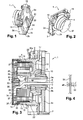
- the electric machine 1 shown in the figures is intended for the drive of unrepresented elevator cables and comprises a frame 2 intended to be fixed for example on a structural element of an elevator shaft.
- This frame 2 carries a stator 3 which can be seen in section in FIG.
- the machine 1 also comprises a rotor 4 rotating relative to the frame 2 and to the stator 3 around a geometric axis of rotation X.
- the frame 2 comprises a flange 2a, extending perpendicular to the axis X, provided at its base with edges 2b provided with orifices 2c intended for the passage of elements of fixing on the support structure.
- Ribs 2d make it possible to stiffen the flange 2a.
- the frame 2 comprises a hollow fixed shaft 6, which extends coaxially at the X axis and at an axial end 7 which is fixed by bolts 8 the stator 3.
- the rotor 4 is mounted on bearings 9 and 10 carried by cylindrical surfaces of revolution of the tree 6.
- the shaft 6 is made by assembling a sleeve 6a and an outer sleeve 6b, the two sleeves being coaxial.
- the outer sleeve 6b is welded to the flange 2a while the sleeve 6a is welded inside the outer sleeve 6b and extends out of it away from the flange 2a to support the bearing 9.
- the sleeves 6a and 6b are each shouldered to allow the bearings corresponding 9 and 10 to come axially on it.
- the shaft 6 could be monobloc.
- the rotor 4 comprises a body monobloc 12 which has a tubular skirt 15 including a portion 13 of the surface inner is cylindrical with X-axis revolution.
- Permanent magnets 14 are fixed, for example by gluing, on this portion 13.
- the body 12 also comprises a disc 17 which connects to the end of the skirt 15 adjacent to the frame 2 and on which brake jaws can engage 19 known in themselves, to brake the rotor, for example in the absence of power stator 3.
- the brakes 19 are for example electrically controlled and comprise jaws coated with friction linings which grip the disk 17 during the braking.
- Grooves 22 are formed on an outer drive surface 15a of the skirt 15, near the end thereof adjacent to the disc 17, to receive the cables or belts for training.
- the stator 3 comprises a central element 25 removably fixed by the bolts 8 on the hollow shaft 6 and serving as a support for a package of plates 26 defining teeth on which coils are engaged 27.
- stator is wound on teeth, each tooth carrying a winding which is this type of winding is still designated by the English terminology "Concentrated winding".
- the stator could alternatively be wound otherwise.
- the central element 25 comprises a central opening 28 allowing the passage of a cable 30 for supplying the windings 27 of the stator, this cable 30 running internally through the shaft 6 and extending outside the machine to be connected to the a dimmer, for example.
- the cable 30 comprises for example four conductors 6 mm 2 section.
- the machine also comprises a position sensor 32 shown schematically in Figure 3, having a rotary shaft 33 rotating with the rotor, being driven by a rod 34 fixed by screws 35 at the end of the skirt 15 opposite the disc 17.
- the rod 34 is covered by a protective cover 37, which rotates with the rotor.
- the position sensor 32 delivers information concerning the position of the rotor relative to the stator, information that is conveyed by a cable 39 not entirely apparent in Figure 3, which also passes through the opening 28 and runs internally the shaft 6 to open out of the engine side of the frame 2.
- the electric machine can be used to drive not a elevator but for example a tire in the case of a driving wheel, or a winch.
- the electric motor can still be realized differently, in particular in which concerns the assembly of the magnets and the disposition of the stator windings.
- the motor extends almost entirely to the interior of the room in which are made the grooves of drive cables or belts but a longer motor could be used without changing the positioning said grooves relative to the flange of the frame.
- the rod 34 can, as illustrated in FIG. 4, pass through an opening 45 of the axis 33 of the position sensor, with a possibility of movement relative to this axis 33. This can reduce the mechanical stress on the axis 33 in case of eccentricity of the rotor.
Landscapes
- Engineering & Computer Science (AREA)
- Power Engineering (AREA)
- Cage And Drive Apparatuses For Elevators (AREA)
- Connection Of Motors, Electrical Generators, Mechanical Devices, And The Like (AREA)
- Permanent Magnet Type Synchronous Machine (AREA)
- Lift-Guide Devices, And Elevator Ropes And Cables (AREA)
- Electrical Discharge Machining, Electrochemical Machining, And Combined Machining (AREA)
- Hydrogen, Water And Hydrids (AREA)
- Types And Forms Of Lifts (AREA)
- Elevator Control (AREA)
Abstract
Description
- un bâti de support,
- un stator fixé en porte-à-faux sur le bâti,
- un rotor monté rotatif sur le bâti autour d'un axe géométrique de rotation de façon à pouvoir être entraíné par le stator,
- les figures 1 et 2 sont deux vues en perspective sous des angles différents d'un exemple de machine réalisée conformément à l'invention,
- la figure 3 est une coupe axiale schématique de la machine des figures 1 et 2, et
- la figure 4 représente un détail de réalisation d'une variante de mise en oeuvre de l'invention.
Claims (12)
- Machine électrique (1) caractérisée par le fait qu'elle comporte :le bâti comportant un arbre central creux (6), coaxial à l'axe géométrique de rotation du rotor, un câble électrique d'alimentation du stator parcourant intérieurement l'arbre (6) et le rotor présentant une surface d'entraínement (15a) destinée à transmettre le couple à au moins un élément à entraíner, tel que par exemple un câble ou une courroie, qui se situe au moins partiellement autour de l'arbre, notamment à proximité immédiate du bâti.un bâti (2) de support,un stator (3) fixé en porte-à-faux sur le bâti (2),un rotor (4) monté rotatif sur le bâti autour d'un axe géométrique de rotation (X) de façon à pouvoir être entraíné par le stator,
- Machine selon la revendication 1, caractérisée par le fait que la surface d'entraínement (15a) se situe au moins en majeure partie autour de l'arbre (6).
- Machine selon la revendication 1 ou 2, caractérisée par le fait qu'un câble (39) relié à un capteur de position (32) parcourt intérieurement l'arbre (6).
- Machine selon l'une quelconque des revendications précédentes, caractérisée par le fait que la surface d'entraínement (15a) comporte des gorges (22) de réception de câbles ou courroies entraínés par la machine.
- Machine selon l'une quelconque des revendications précédentes, caractérisée par le fait que le rotor comporte un disque (17) orienté perpendiculairement à l'axe géométrique de rotation (X) et par le fait que le bâti porte au moins un frein (19) comportant un organe de friction agencé pour s'appliquer sur ce disque (17).
- Machine selon l'une quelconque des revendications précédentes, caractérisée par le fait qu'elle comporte, du côté opposé à l'extrémité de l'arbre par laquelle sort(ent) le ou les câbles parcourant intérieurement celui-ci, un capot amovible (37).
- Machine selon la revendication précédente, caractérisée par le fait que le capot amovible recouvre une tige (34) tournant avec le rotor et entraínant en rotation un axe (33) d'un capteur de position.
- Machine selon la revendication 7, caractérisée par le fait que l'axe (33) comporte une ouverture (45) traversée par la tige (34).
- Machine selon l'une quelconque des revendications précédentes, caractérisée par le fait que le rotor comporte une surface intérieure (13) cylindrique de révolution, sur laquelle des aimants permanents (14) sont fixés.
- Machine selon l'une quelconque des revendications précédentes, caractérisée par le fait que le stator est boulonné sur l'arbre (6).
- Machine selon l'une quelconque des revendications précédentes, caractérisée par le fait que le rotor comporte un corps (12) monobloc, portant des aimants (14) et dans lequel sont usinées des gorges (22) de réception de courroies ou câbles destinés à être entraínés par la machine.
- Machine selon l'une quelconque des revendications précédentes, caractérisée par le fait que l'arbre (6) est formé par l'assemblage de deux manchons (6a, 6b) coaxiaux.
Applications Claiming Priority (2)
| Application Number | Priority Date | Filing Date | Title |
|---|---|---|---|
| FR0309784A FR2858723B1 (fr) | 2003-08-08 | 2003-08-08 | Machine electrique, notamment pour ascenseur |
| FR0309784 | 2003-08-08 |
Publications (2)
| Publication Number | Publication Date |
|---|---|
| EP1505030A1 true EP1505030A1 (fr) | 2005-02-09 |
| EP1505030B1 EP1505030B1 (fr) | 2008-10-22 |
Family
ID=33548324
Family Applications (1)
| Application Number | Title | Priority Date | Filing Date |
|---|---|---|---|
| EP04300482A Expired - Lifetime EP1505030B1 (fr) | 2003-08-08 | 2004-07-27 | Machine électrique, notamment pour ascenseur |
Country Status (7)
| Country | Link |
|---|---|
| US (1) | US7166946B2 (fr) |
| EP (1) | EP1505030B1 (fr) |
| CN (1) | CN1599203B (fr) |
| AT (1) | ATE411965T1 (fr) |
| DE (1) | DE602004017256D1 (fr) |
| ES (1) | ES2316945T3 (fr) |
| FR (1) | FR2858723B1 (fr) |
Cited By (1)
| Publication number | Priority date | Publication date | Assignee | Title |
|---|---|---|---|---|
| EP1550630A3 (fr) * | 2003-12-23 | 2007-01-10 | ThyssenKrupp Aufzugswerke GmbH | Moteur électrique pour ascenseur |
Families Citing this family (9)
| Publication number | Priority date | Publication date | Assignee | Title |
|---|---|---|---|---|
| FR2894731A1 (fr) * | 2005-12-09 | 2007-06-15 | Leroy Somer Moteurs | Machine electrique tournante comportant un frein venant en prise avec au moins une surface de freinage s'etendant non entierement perpendiculairement a l'axe de rotation |
| JP5627681B2 (ja) * | 2009-07-10 | 2014-11-19 | オーチス エレベータ カンパニーOtis Elevator Company | トラクションシーブ内に外周側ロータおよびモータを有したエレベータマシン |
| WO2012010971A2 (fr) * | 2010-07-18 | 2012-01-26 | Graeme John Freedman | Dispositif inviolable pour circuits imprimés |
| JP5754548B2 (ja) * | 2012-04-07 | 2015-07-29 | トヨタ自動車株式会社 | 摩擦ブレーキ装置 |
| US20160101966A1 (en) * | 2013-05-28 | 2016-04-14 | Otis Elevator Company | Elevator machine with recessed bearings |
| US10081518B2 (en) | 2013-05-28 | 2018-09-25 | Otis Elevator Company | Elevator machine and stator support structure |
| DE102015005360B3 (de) * | 2015-04-28 | 2016-06-23 | Sew-Eurodrive Gmbh & Co Kg | Getriebesystem |
| TWI659592B (zh) * | 2018-02-09 | 2019-05-11 | 建準電機工業股份有限公司 | 吊扇馬達套管 |
| CN108599455B (zh) * | 2018-04-28 | 2019-09-06 | 上海交通大学 | 一种用于电机的无输入断电自锁装置 |
Citations (4)
| Publication number | Priority date | Publication date | Assignee | Title |
|---|---|---|---|---|
| US5018603A (en) * | 1988-08-26 | 1991-05-28 | Mitsubishi Denki Kabushiki Kaisha | Elevator hoist apparatus |
| EP0834463A1 (fr) * | 1996-10-07 | 1998-04-08 | Inventio Ag | Dispositif compact d'entraínement pour ascenseur |
| EP0970912A2 (fr) * | 1998-07-07 | 2000-01-12 | Hitachi, Ltd. | Ascenseur |
| EP1057772A2 (fr) * | 1999-06-02 | 2000-12-06 | Teijin Seiki Co., Ltd. | Ensemble d'entrainement pour ascenseur |
Family Cites Families (14)
| Publication number | Priority date | Publication date | Assignee | Title |
|---|---|---|---|---|
| IT1142978B (it) * | 1980-10-29 | 1986-10-15 | Pierburg Gmbh & Co Kg | Regolatore rotativo in particolare per carburatori di motori a combustione interna |
| FI811414A7 (fi) * | 1981-05-07 | 1982-11-08 | Elevator Gmbh | Taajuusmuuttajaohjattu oikosulkumoottori. |
| FR2593976B2 (fr) | 1985-10-03 | 1989-08-11 | Ducellier & Cie | Rotor pour machine dynamo-electrique notamment pour alternateur de vehicule automobile |
| US5107158A (en) * | 1990-10-01 | 1992-04-21 | Rockwell International Corporation | Diametral runout reducer for rotating shaft |
| US5783895A (en) * | 1994-04-07 | 1998-07-21 | Kone Oy | Elevator motor with flat construction |
| US5992655A (en) | 1997-09-08 | 1999-11-30 | Greenberg; Alan S. | Caterpillar sideboom replacement assembly |
| US6057616A (en) * | 1998-04-02 | 2000-05-02 | Seagate Technology, Inc. | Stator interconnect ring |
| JP3698592B2 (ja) | 1999-07-12 | 2005-09-21 | 三菱電機株式会社 | 巻上機 |
| FR2821024B1 (fr) * | 2001-02-20 | 2003-06-13 | Leroy Somer Moteurs | Element d'entrainement tel qu'une roue motrice ou un treuil de levage, comportant un moteur synchrone |
| US6593674B2 (en) * | 2001-02-26 | 2003-07-15 | Woodward Governor Company | Vibration isolator and actuator incorporating same for isolating integral electronics |
| JP2002274770A (ja) | 2001-03-14 | 2002-09-25 | Mitsubishi Electric Corp | エレベータ用ギヤーレス巻上機 |
| JP2003269474A (ja) * | 2002-03-14 | 2003-09-25 | Ntn Corp | 発電機能付軸受 |
| JP2004035120A (ja) | 2002-06-28 | 2004-02-05 | Ts Corporation | エレベータ用昇降駆動装置 |
| JP2004135448A (ja) | 2002-10-11 | 2004-04-30 | Kyowa Seisakusho:Kk | 電動モータ |
-
2003
- 2003-08-08 FR FR0309784A patent/FR2858723B1/fr not_active Expired - Fee Related
-
2004
- 2004-06-22 US US10/872,453 patent/US7166946B2/en not_active Expired - Fee Related
- 2004-07-20 CN CN200410070811.5A patent/CN1599203B/zh not_active Expired - Fee Related
- 2004-07-27 AT AT04300482T patent/ATE411965T1/de not_active IP Right Cessation
- 2004-07-27 ES ES04300482T patent/ES2316945T3/es not_active Expired - Lifetime
- 2004-07-27 DE DE602004017256T patent/DE602004017256D1/de not_active Expired - Lifetime
- 2004-07-27 EP EP04300482A patent/EP1505030B1/fr not_active Expired - Lifetime
Patent Citations (4)
| Publication number | Priority date | Publication date | Assignee | Title |
|---|---|---|---|---|
| US5018603A (en) * | 1988-08-26 | 1991-05-28 | Mitsubishi Denki Kabushiki Kaisha | Elevator hoist apparatus |
| EP0834463A1 (fr) * | 1996-10-07 | 1998-04-08 | Inventio Ag | Dispositif compact d'entraínement pour ascenseur |
| EP0970912A2 (fr) * | 1998-07-07 | 2000-01-12 | Hitachi, Ltd. | Ascenseur |
| EP1057772A2 (fr) * | 1999-06-02 | 2000-12-06 | Teijin Seiki Co., Ltd. | Ensemble d'entrainement pour ascenseur |
Cited By (1)
| Publication number | Priority date | Publication date | Assignee | Title |
|---|---|---|---|---|
| EP1550630A3 (fr) * | 2003-12-23 | 2007-01-10 | ThyssenKrupp Aufzugswerke GmbH | Moteur électrique pour ascenseur |
Also Published As
| Publication number | Publication date |
|---|---|
| US7166946B2 (en) | 2007-01-23 |
| DE602004017256D1 (de) | 2008-12-04 |
| US20050029883A1 (en) | 2005-02-10 |
| ES2316945T3 (es) | 2009-04-16 |
| EP1505030B1 (fr) | 2008-10-22 |
| CN1599203B (zh) | 2011-05-25 |
| ATE411965T1 (de) | 2008-11-15 |
| FR2858723B1 (fr) | 2005-12-30 |
| CN1599203A (zh) | 2005-03-23 |
| FR2858723A1 (fr) | 2005-02-11 |
Similar Documents
| Publication | Publication Date | Title |
|---|---|---|
| EP1241038B1 (fr) | Elément d'entraînement tel qu'une roue motrice ou un treuil de levage, comportant un moteur synchrone | |
| EP1411620B1 (fr) | Machine comportant une poulie et un moteur électrique, notamment pour ascenseur | |
| FR2500688A1 (fr) | Groupe electrique d'entrainement avec poulie supportee par le carter | |
| EP1505030B1 (fr) | Machine électrique, notamment pour ascenseur | |
| FR3001449A1 (fr) | Machine d'entrainement d'un ascenseur. | |
| FR2894731A1 (fr) | Machine electrique tournante comportant un frein venant en prise avec au moins une surface de freinage s'etendant non entierement perpendiculairement a l'axe de rotation | |
| EP2618465B1 (fr) | Machine électrique comprenant deux rotors et au moins deux paliers, avec un seul palier agencé entre les deux rotors suivant l'axe de rotation | |
| EP1715564B1 (fr) | Dispositif de freinage d'un arbre rotatif d'une source d'entraînement, telle qu'un moteur électrique | |
| EP0500429A1 (fr) | Dispositif pour l'échange de chaleur | |
| FR3064131A1 (fr) | Rotor de machine electrique tournante muni de flasques d'equilibrage ameliores | |
| FR2922060A1 (fr) | Machine electrique tournante comportant deux stators | |
| FR2648638A1 (fr) | Perfectionnements aux transmissions de vehicules equipees de ralentisseurs electriques | |
| EP4179610B1 (fr) | Motoréducteur à enveloppe cylindrique et moteur tubulaire correspondant | |
| EP1610026A1 (fr) | Etrier de frein à disque électromécanique | |
| FR2859951A1 (fr) | Groupe d'entrainement pour un chariot transporteur notamment un chariot elevateur a timon | |
| FR2617751A1 (fr) | Articulation motorisee de robot | |
| EP0789442A1 (fr) | Transmission de véhicule équipée d'un ralentisseur électrique | |
| FR3124036A1 (fr) | Machine électrique tournante à flux axial multiple ayant une configuration creuse | |
| WO2018178535A1 (fr) | Machine electrique tournante a configuration modifiee pour faciliter la montabilite d'un element fonctionnel | |
| WO2025103725A1 (fr) | Actionneur pour un bras robotisé à configuration améliorée | |
| FR2893460A1 (fr) | Machine electrique tournante. | |
| WO2026057462A1 (fr) | Dispositif d'alimentation électrique pour un rotor bobiné | |
| FR3153706A1 (fr) | Motoréducteur et procédé d’assemblage associé | |
| FR2671676A1 (fr) | Structure de machine tournante electrique. | |
| FR2821023A1 (fr) | Roue motrice a moteur synchrone |
Legal Events
| Date | Code | Title | Description |
|---|---|---|---|
| PUAI | Public reference made under article 153(3) epc to a published international application that has entered the european phase |
Free format text: ORIGINAL CODE: 0009012 |
|
| AK | Designated contracting states |
Kind code of ref document: A1 Designated state(s): AT BE BG CH CY CZ DE DK EE ES FI FR GB GR HU IE IT LI LU MC NL PL PT RO SE SI SK TR |
|
| AX | Request for extension of the european patent |
Extension state: AL HR LT LV MK |
|
| 17P | Request for examination filed |
Effective date: 20050609 |
|
| AKX | Designation fees paid |
Designated state(s): AT BE BG CH CY CZ DE DK EE ES FI FR GB GR HU IE IT LI LU MC NL PL PT RO SE SI SK TR |
|
| GRAP | Despatch of communication of intention to grant a patent |
Free format text: ORIGINAL CODE: EPIDOSNIGR1 |
|
| GRAS | Grant fee paid |
Free format text: ORIGINAL CODE: EPIDOSNIGR3 |
|
| GRAA | (expected) grant |
Free format text: ORIGINAL CODE: 0009210 |
|
| AK | Designated contracting states |
Kind code of ref document: B1 Designated state(s): AT BE BG CH CY CZ DE DK EE ES FI FR GB GR HU IE IT LI LU MC NL PL PT RO SE SI SK TR |
|
| REG | Reference to a national code |
Ref country code: GB Ref legal event code: FG4D Free format text: NOT ENGLISH |
|
| REG | Reference to a national code |
Ref country code: CH Ref legal event code: EP |
|
| REG | Reference to a national code |
Ref country code: IE Ref legal event code: FG4D Free format text: LANGUAGE OF EP DOCUMENT: FRENCH |
|
| REF | Corresponds to: |
Ref document number: 602004017256 Country of ref document: DE Date of ref document: 20081204 Kind code of ref document: P |
|
| NLV1 | Nl: lapsed or annulled due to failure to fulfill the requirements of art. 29p and 29m of the patents act | ||
| REG | Reference to a national code |
Ref country code: ES Ref legal event code: FG2A Ref document number: 2316945 Country of ref document: ES Kind code of ref document: T3 |
|
| PG25 | Lapsed in a contracting state [announced via postgrant information from national office to epo] |
Ref country code: BG Free format text: LAPSE BECAUSE OF FAILURE TO SUBMIT A TRANSLATION OF THE DESCRIPTION OR TO PAY THE FEE WITHIN THE PRESCRIBED TIME-LIMIT Effective date: 20090122 Ref country code: AT Free format text: LAPSE BECAUSE OF FAILURE TO SUBMIT A TRANSLATION OF THE DESCRIPTION OR TO PAY THE FEE WITHIN THE PRESCRIBED TIME-LIMIT Effective date: 20081022 |
|
| PG25 | Lapsed in a contracting state [announced via postgrant information from national office to epo] |
Ref country code: SI Free format text: LAPSE BECAUSE OF FAILURE TO SUBMIT A TRANSLATION OF THE DESCRIPTION OR TO PAY THE FEE WITHIN THE PRESCRIBED TIME-LIMIT Effective date: 20081022 Ref country code: PT Free format text: LAPSE BECAUSE OF FAILURE TO SUBMIT A TRANSLATION OF THE DESCRIPTION OR TO PAY THE FEE WITHIN THE PRESCRIBED TIME-LIMIT Effective date: 20090323 Ref country code: PL Free format text: LAPSE BECAUSE OF FAILURE TO SUBMIT A TRANSLATION OF THE DESCRIPTION OR TO PAY THE FEE WITHIN THE PRESCRIBED TIME-LIMIT Effective date: 20081022 Ref country code: FI Free format text: LAPSE BECAUSE OF FAILURE TO SUBMIT A TRANSLATION OF THE DESCRIPTION OR TO PAY THE FEE WITHIN THE PRESCRIBED TIME-LIMIT Effective date: 20081022 Ref country code: NL Free format text: LAPSE BECAUSE OF FAILURE TO SUBMIT A TRANSLATION OF THE DESCRIPTION OR TO PAY THE FEE WITHIN THE PRESCRIBED TIME-LIMIT Effective date: 20081022 |
|
| REG | Reference to a national code |
Ref country code: IE Ref legal event code: FD4D |
|
| PG25 | Lapsed in a contracting state [announced via postgrant information from national office to epo] |
Ref country code: EE Free format text: LAPSE BECAUSE OF FAILURE TO SUBMIT A TRANSLATION OF THE DESCRIPTION OR TO PAY THE FEE WITHIN THE PRESCRIBED TIME-LIMIT Effective date: 20081022 Ref country code: DK Free format text: LAPSE BECAUSE OF FAILURE TO SUBMIT A TRANSLATION OF THE DESCRIPTION OR TO PAY THE FEE WITHIN THE PRESCRIBED TIME-LIMIT Effective date: 20081022 Ref country code: IE Free format text: LAPSE BECAUSE OF FAILURE TO SUBMIT A TRANSLATION OF THE DESCRIPTION OR TO PAY THE FEE WITHIN THE PRESCRIBED TIME-LIMIT Effective date: 20081022 Ref country code: RO Free format text: LAPSE BECAUSE OF FAILURE TO SUBMIT A TRANSLATION OF THE DESCRIPTION OR TO PAY THE FEE WITHIN THE PRESCRIBED TIME-LIMIT Effective date: 20081022 |
|
| PLBE | No opposition filed within time limit |
Free format text: ORIGINAL CODE: 0009261 |
|
| STAA | Information on the status of an ep patent application or granted ep patent |
Free format text: STATUS: NO OPPOSITION FILED WITHIN TIME LIMIT |
|
| PG25 | Lapsed in a contracting state [announced via postgrant information from national office to epo] |
Ref country code: SE Free format text: LAPSE BECAUSE OF FAILURE TO SUBMIT A TRANSLATION OF THE DESCRIPTION OR TO PAY THE FEE WITHIN THE PRESCRIBED TIME-LIMIT Effective date: 20090122 Ref country code: CZ Free format text: LAPSE BECAUSE OF FAILURE TO SUBMIT A TRANSLATION OF THE DESCRIPTION OR TO PAY THE FEE WITHIN THE PRESCRIBED TIME-LIMIT Effective date: 20081022 |
|
| 26N | No opposition filed |
Effective date: 20090723 |
|
| PG25 | Lapsed in a contracting state [announced via postgrant information from national office to epo] |
Ref country code: SK Free format text: LAPSE BECAUSE OF FAILURE TO SUBMIT A TRANSLATION OF THE DESCRIPTION OR TO PAY THE FEE WITHIN THE PRESCRIBED TIME-LIMIT Effective date: 20081022 |
|
| BERE | Be: lapsed |
Owner name: MOTEURS LEROY-SOMER Effective date: 20090731 |
|
| PG25 | Lapsed in a contracting state [announced via postgrant information from national office to epo] |
Ref country code: MC Free format text: LAPSE BECAUSE OF NON-PAYMENT OF DUE FEES Effective date: 20090731 |
|
| REG | Reference to a national code |
Ref country code: CH Ref legal event code: PL |
|
| PG25 | Lapsed in a contracting state [announced via postgrant information from national office to epo] |
Ref country code: CH Free format text: LAPSE BECAUSE OF NON-PAYMENT OF DUE FEES Effective date: 20090731 Ref country code: LI Free format text: LAPSE BECAUSE OF NON-PAYMENT OF DUE FEES Effective date: 20090731 |
|
| PG25 | Lapsed in a contracting state [announced via postgrant information from national office to epo] |
Ref country code: BE Free format text: LAPSE BECAUSE OF NON-PAYMENT OF DUE FEES Effective date: 20090731 |
|
| PG25 | Lapsed in a contracting state [announced via postgrant information from national office to epo] |
Ref country code: GR Free format text: LAPSE BECAUSE OF FAILURE TO SUBMIT A TRANSLATION OF THE DESCRIPTION OR TO PAY THE FEE WITHIN THE PRESCRIBED TIME-LIMIT Effective date: 20090123 |
|
| PGFP | Annual fee paid to national office [announced via postgrant information from national office to epo] |
Ref country code: ES Payment date: 20100730 Year of fee payment: 7 |
|
| PGFP | Annual fee paid to national office [announced via postgrant information from national office to epo] |
Ref country code: IT Payment date: 20100727 Year of fee payment: 7 |
|
| PGFP | Annual fee paid to national office [announced via postgrant information from national office to epo] |
Ref country code: GB Payment date: 20100720 Year of fee payment: 7 |
|
| PGFP | Annual fee paid to national office [announced via postgrant information from national office to epo] |
Ref country code: DE Payment date: 20100923 Year of fee payment: 7 |
|
| PG25 | Lapsed in a contracting state [announced via postgrant information from national office to epo] |
Ref country code: LU Free format text: LAPSE BECAUSE OF NON-PAYMENT OF DUE FEES Effective date: 20090727 |
|
| PG25 | Lapsed in a contracting state [announced via postgrant information from national office to epo] |
Ref country code: HU Free format text: LAPSE BECAUSE OF FAILURE TO SUBMIT A TRANSLATION OF THE DESCRIPTION OR TO PAY THE FEE WITHIN THE PRESCRIBED TIME-LIMIT Effective date: 20090423 |
|
| PG25 | Lapsed in a contracting state [announced via postgrant information from national office to epo] |
Ref country code: TR Free format text: LAPSE BECAUSE OF FAILURE TO SUBMIT A TRANSLATION OF THE DESCRIPTION OR TO PAY THE FEE WITHIN THE PRESCRIBED TIME-LIMIT Effective date: 20081022 |
|
| PG25 | Lapsed in a contracting state [announced via postgrant information from national office to epo] |
Ref country code: CY Free format text: LAPSE BECAUSE OF FAILURE TO SUBMIT A TRANSLATION OF THE DESCRIPTION OR TO PAY THE FEE WITHIN THE PRESCRIBED TIME-LIMIT Effective date: 20081022 |
|
| GBPC | Gb: european patent ceased through non-payment of renewal fee |
Effective date: 20110727 |
|
| PG25 | Lapsed in a contracting state [announced via postgrant information from national office to epo] |
Ref country code: DE Free format text: LAPSE BECAUSE OF NON-PAYMENT OF DUE FEES Effective date: 20120201 |
|
| REG | Reference to a national code |
Ref country code: DE Ref legal event code: R119 Ref document number: 602004017256 Country of ref document: DE Effective date: 20120201 |
|
| PG25 | Lapsed in a contracting state [announced via postgrant information from national office to epo] |
Ref country code: IT Free format text: LAPSE BECAUSE OF NON-PAYMENT OF DUE FEES Effective date: 20110727 |
|
| PG25 | Lapsed in a contracting state [announced via postgrant information from national office to epo] |
Ref country code: GB Free format text: LAPSE BECAUSE OF NON-PAYMENT OF DUE FEES Effective date: 20110727 |
|
| REG | Reference to a national code |
Ref country code: ES Ref legal event code: FD2A Effective date: 20121207 |
|
| PG25 | Lapsed in a contracting state [announced via postgrant information from national office to epo] |
Ref country code: ES Free format text: LAPSE BECAUSE OF NON-PAYMENT OF DUE FEES Effective date: 20110728 |
|
| REG | Reference to a national code |
Ref country code: FR Ref legal event code: PLFP Year of fee payment: 12 |
|
| PGFP | Annual fee paid to national office [announced via postgrant information from national office to epo] |
Ref country code: FR Payment date: 20150630 Year of fee payment: 12 |
|
| PG25 | Lapsed in a contracting state [announced via postgrant information from national office to epo] |
Ref country code: FR Free format text: LAPSE BECAUSE OF NON-PAYMENT OF DUE FEES Effective date: 20160801 |
|
| REG | Reference to a national code |
Ref country code: FR Ref legal event code: ST Effective date: 20170331 |