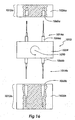
BACKGROUND OF THE INVENTION
1. Field of the Invention
The present invention relates to medical systems and devices. More specifically, the
present invention relates to catheter assemblies which include catheters and catheter adapters
produced as a single part or produced as integrated assemblies of multiple parts. The
invention further includes methods of injection molding and apparatus for producing such
catheter assemblies from a single material and from multiple materials.
2. Description of Related Art
In an age of medicine in which injectable pharmaceuticals are ubiquitous in patient
treatment regimens, indwelling catheters are a critical tool used in hospitals daily. Many
medical treatments are dependent on devices and methods which allow the introduction of
fluids into the body of a patient. Advances in catheter-related technologies have allowed a
larger number of medical procedures to be performed intravenously instead of surgically.
Indeed, procedures such as angioplasty and exploratory surgery may now be completed
without making any incisions other than the puncture necessary to access a blood vessel and
insert a catheter.
One type of commonly-used catheter is a peripheral intravenous catheter. These short,
indwelling intravenous catheters are often used to provide an entry route for medications,
fluid for hydration, and in some cases, for parenteral feeding. Such catheters are generally
short in length, ranging from about one-half to about three inches in length. These catheters
are generally made of flexible biocompatible materials. In some cases, these catheters
additionally include a radiopaque compound such as barium sulfate to allow the location of
the catheters to be tracked once inside the body.
Injection molding technologies have become very popular for use in producing plastic
components, including many medical devices. The speed, efficiency, and consistency of
these processes often results in time or cost savings to a manufacturer. Long, thin, tubular
objects such as catheters have traditionally been very difficult to produce using such injection
molding technologies. This difficulty arises for a number of reasons. First, the extremely
high pressures involved in injection molding processes generally render proposed processes
unusable. Typically, to provide a rapid fill, the molten plastic must be pressurized to several
thousand pounds per square inch. As a result, when flows of the highly-pressurized plastic
are allowed to enter the cavity of the injection mold, any imbalance in the flows, regardless of
how slight, may deflect the core pin used to produce the tubular lumen of the component from
its proper position. This often results in a damaged, and potentially unusable, product.
In answer to this problem, injection molding systems have been produced which have
multiple gates through which the molten plastic is introduced. This results in multiple flows
of molten plastic flowing into the mold. By providing multiple flows of molten plastic,
imbalances in flow may generally be reduced. Despite this, however, flow imbalances may
still occur. In many such cases these flow imbalances occur at least in part because the
multiple flows may not enter the cavity in a simultaneous manner. In addition, imbalanced
flows may occur when the flows of plastic are not evenly distributed about the core pin.
Another attempt to compensate for these factors has involved the production of
injection molds and associated equipment which utilize a core pin which is placed in tension.
Use of such systems and additional research have shown, however, that even in systems
where the core pin is placed in high tension, imbalanced material flows may deflect the core
pin, thus causing the part produced in the mold to have a number of undesirable
characteristics. In many cases, these qualities include poor molecular orientation, excessive
production of flash, internal stresses, and the like. In many cases, these flaws may be
significant enough to impair the performance of the part or render it inoperative.
As a result of these difficulties, many thin tubular parts are produced using
manufacturing processes such as extrusion which do not involve high-pressure injection-molding.
Often, these alternate manufacturing procedures reduce ability of the producer to
vary the shape, size, and overall geometry of the parts to be produced. As a result, thin
tubular parts are first produced, and then in subsequent steps attached to other parts through
separate processing steps. As discussed above, such post-production processing and the use
of supplementary parts may be disadvantageous because of increased material and labor costs
which may be associated with them.
Catheter assemblies comprising a catheter linked to a catheter adapter have typically
been produced in a multi-step process such as those discussed above. Generally, the adapter
portion is produced separately from the catheter portion and later attached. Following
production of the components, the catheter is joined to the catheter adapter by threading the
catheter into the adapter and attaching them to each other using a swage. In addition to this
attachment step, the catheter portion may require a separate tipping process to provide a
catheter with suitable tip geometry.
SUMMARY OF THE INVENTION
The apparatus of the present invention has been developed in response to the present
state of the art, and in particular, in response to the problems and needs in the art that have not
yet been fully solved by currently available catheter assemblies and catheter assembly
manufacturing methods and equipment. Thus, it is an overall objective of the present
invention to provide injection-molded catheter assemblies including a catheter adapter and a
catheter tube, as well as methods of manufacture and associated equipment by which such
injection-molded catheter assemblies may be produced.
In accordance with the invention as embodied and broadly described herein, catheter
assemblies are provided which include a catheter and an adapter either produced as a single
component or separately in such a fashion that the fmal product is an integrally-joined
assembly. The invention further provides methods and associated apparatus for producing
these catheter assemblies by injection molding. The catheter assemblies of the invention
include a catheter adapter or "catheter hub" and a catheter tube or "cannula." In some
embodiments, the hub and cannula of the catheter assembly may be formed as a single
component of a single material in a single step. In such a catheter assembly, the hub and
cannula are continuous with each other, and are integrally formed. The invention includes
methods and apparatus for producing such single-material one-piece catheter assemblies.
In other embodiments of the invention, the catheter assembly comprises a hub portion
and a cannula portion which may be produced of different materials and in separate steps, but
which are integrally attached to each other in the completed catheter assembly. This may
generally involve producing one of the components first, and then subsequently overmolding
the second component onto the first. In some embodiments, the hub is produced first and the
catheter is subsequently overmolded. In others, the catheter portion is produced first and the
hub is later molded about the catheter. The catheter assemblies of the invention may also be
produced using injection molding methods in which the catheter and hub portions are
produced substantially simultaneously.
In some embodiments, the hub portion and the cannula portion are attached to each
other by bonds formed between the materials used to produce each portion during
manufacturing. These bonds generally include non-covalent bonds such as electrostatic
bonds, van der Waals interactions, or other chemical interactions or bonds. In addition, the
hub portion and the cannula portion may be attached to each other by physical entanglement
of the polymers used in the separate components.
In other embodiments, the hub portion and the cannula portion are attached to each
other using a mechanical interlock interface created during manufacture of the components.
In still other embodiments, the hub portion is attached to the cannula portion using a
combination of the bonding of the materials, physical interaction of the polymers used in the
components, and mechanical interlocking interfaces.
In the catheter assemblies of the invention, the hub portion of the catheter assembly is
a generally tubular component used as an interface between the cannula portion and devices
for introducing or withdrawing fluid from the body such as syringes. The hub portion
includes a hub barrel, hub base, and a hub adapter. The hub barrel is the main tubular body of
the catheter hub and includes a lumen for receiving a tip portion of a fluid
withdrawal/introduction device such as a syringe or IV line, and for conveyance of fluid. The
hub barrel is generally tapered internally and externally. The hub base protrudes from an end
of the hub barrel in the form of a ridge. This ridge may further include flanges such as luer
threads for locking the catheter assembly to an external device such as a syringe or an IV line
in a secure, and often sealed, fashion. The flanges may also assist a user in grasping the hub
barrel of the catheter assemblies of the invention.
The present invention also provides a method and related apparatus by which the
single-material, single-part catheter assemblies of the invention may be manufactured through
the use of injection molding processes. The invention provides a mold used for the injection
molding of a single-material catheter assembly. This mold generally includes an A-side and a
B-side which mate to form a cavity shaped to form a catheter assembly. The mold is
configured to be coupled to a nozzle of a plastic injection system in order to receive a flow of
molten plastic which is channeled to the cavity to form the catheter assembly. The A-side
may have a cavity plate for receiving the flow or flows of molten plastic and for forming the
catheter assembly. The B-side of the mold may have a floating plate for transmitting a flow
or flows of molten plastic, as well as a base plate.
As briefly discussed above, the sides of the mold are configured to mate to produce a
cavity into which plastic can be injected to form the catheter assembly. The cavity may be
sealed in plastic-tight fashion such that gas can escape the cavity during inj ection, but plastic
is unable to escape. A core pin generally protrudes into the cavity from the floating and base
plates such that the cavity has a generally annular shape. The cavity may have a hub portion
in which the hub is formed, and a catheter portion in which the catheter is formed. In molds
for producing the single-material single-part catheter assemblies of the invention, the hub
portions and catheter portions of the mold may be continuous with each other. The core pin
may traverse the hub and catheter portions of the mold to define the lumen of the hub and the
catheter. The cavity of the mold is further configured to provide a proper geometry to the tip
of the completed catheter assembly.
The invention also provides methods and apparatus for forming the multi-material
integrated catheter assemblies of the invention. Such methods include methods for producing
an integrated two-piece (and hence potentially two-material) catheter assembly using two-shot
or multi-shot injection molding techniques or using simple overmolding techniques. In each
case, the mold is similar to that described above, with the exception that the cavity is
configured to allow individual molding of either the catheter portion or the hub portion of the
assembly first, and then to subsequently allow the molding of the remaining component or
components about the first-molded part. This may be accomplished in a two-shot or multi-shot
injection molding process by providing a modular cavity which segregates regions of the
cavity until a first component has been molded, and then opens the remainder of the cavity to
allow overmolding of the remaining part.
Similarly, overmolding techniques of providing a separate mold for the first
component and a second mold configured to retain the molded first component and overmold
the remaining one are taught. With overmolding, as above, either the catheter portion or the
hub portion may be produced first, and then the remaining part subsequently overmolded
about the first-produced part.
The molds of the invention may form the catheter assembly with a high degree of
molecular alignment along its length by providing a comparatively even flow of molten
plastic around the circumference of the annular cavity defining the catheter assembly. Such
an even flow may be provided by providing a plurality of flows that converge and flow into
the annular cavity substantially simultaneously.
In one example of this, floating plates of the molds of the invention may have a pair of
substantially symmetrical flow paths through which molten plastic is able to travel from the
nozzle to the hub portion of the cavity. Opposite sides of the hub portion of the cavity may
have a gate region through which molten plastic emerges from the flow paths to enter the hub
region of the cavity. The molten plastic may then travel through the hub in a substantially
uniform manner. The molten plastic may thus fill the hub in a manner such that it is
substantially evenly distributed about a circumference of the hub. From the hub, the plastic
may enter the catheter portion of the cavity and move to the tip portion while maintaining an
even distribution about the circumference of the cavity.
Thus, the two flows of molten plastic may reach the end of the tip portion
simultaneously. Since molecules of molten plastic tend to align themselves with the direction
in which the plastic flows, the result is a high degree of molecular alignment along the length
of the catheter assembly, including the tip. The strength of the molded plastic part is
generally greatest in the direction with which the molecules are aligned. Thus, the catheter
assembly of the invention has a comparatively high resistance to axial tension and
compression. In alternate methods, the molten plastic may be injected into the cavity such
that it first fills the catheter portion of the cavity and then proceeds to fill the hub portion.
The use of even flows of molten plastic makes it unnecessary to employ extra steps to
protect the core pin against bending. Some traditional injection molding processes utilize an
external mechanism, such as a hydraulically operated clamp, to tension a core pin or other
protrusion to form a bore in the injection molded part. Such mechanisms add to the
complexity of the molding apparatus and increase the cycle time of the injection molding
process, thereby increasing the cost of the injection molded parts. The present invention
avoids this requirement, thus avoiding cost and reducing production time requirements.
After the plastic has been injected into the cavity, forming the catheter assembly, the
mold may be disassembled to allow removal of the completed catheter assembly product.
This often includes moving the B-side of the mold away from the A-side to expose the
molded part. The completed catheter assembly may then be ejected from the core pin and
cavity manually, by ejector pins, stripper plates, robotic removal, or other equipment and
techniques known to one of ordinary skill in the art.
The cavity of the mold may be shaped such that the catheter assembly produced
therein may have accurate tip geometry that promotes easier and more comfortable insertion
of the catheter into a blood vessel. The catheter assembly may be rapidly and inexpensively
manufactured by the injection molding process described above, without the need for separate
attachment or tipping operations. Consequently, the catheter assembly and method of the
present invention may contribute to the comfort, reliability, and cost effectiveness of medical
care.
These and other objects, features, and advantages of the present invention will become
more fully apparent from the following description and appended claims, or may be learned
by the practice of the invention as set forth hereinafter.
BRIEF DESCRIPTION OF THE DRAWINGS
In order that the manner in which the above-recited and other advantages and obj ects
of the invention are obtained will be readily understood, a more particular description of the
invention briefly described above will be rendered by reference to specific embodiments
thereof which are illustrated in the appended drawings. Understanding that these drawings
depict only typical embodiments of the invention and are not therefore to be considered to be
limiting of its scope, the invention will be described and explained with additional specificity
and detail through the use of the accompanying drawings in which:
DETAILED DESCRIPTION OF THE PREFERRED EMBODIMENTS
The presently preferred embodiments of the present invention will be best understood
by reference to the drawings, wherein like parts are designated by like numerals throughout.
It will be readily understood that the components of the present invention, as generally
described and illustrated in the figures herein, could be arranged and designed in a wide
variety of different configurations. Thus, the following more detailed description of the
embodiments of the apparatus, system, and method of the present invention, as represented in
Figures 1 through 16, is not intended to limit the scope of the invention, as claimed, but is
merely representative of presently preferred embodiments of the invention.
The present invention includes advances in catheter design, material selection,
and mold design which combine to enable production of a catheter assembly, including a
catheter hub and a catheter tube, using injection-molding technologies. The invention further
provides catheters which may be constructed using a single material, or using multiple
materials. Among others, the invention provides single-material, bi-material, and tri-material
integrally formed catheter assemblies and methods and molds for their DETAILED
DESCRIPTION OF THE PREFERRED EMBODIMENTS
The presently preferred embodiments of the present invention will be best understood
by reference to the drawings, wherein like parts are designated by like numerals throughout.
It will be readily understood that the components of the present invention, as generally
described and illustrated in the figures herein, could be arranged and designed in a wide
variety of different configurations. Thus, the following more detailed description of the
embodiments of the apparatus, system, and method of the present invention, as represented in
Figures 1 through 16, is not intended to limit the scope of the invention, as claimed, but is
merely representative of presently preferred embodiments of the invention.
The present invention includes advances in catheter design, material selection,
and mold design which combine to enable production of a catheter assembly, including a
catheter hub and a catheter tube, using injection-molding technologies. The invention further
provides catheters which may be constructed using a single material, or using multiple
materials. Among others, the invention provides single-material, bi-material, and tri-material
integrally formed catheter assemblies and methods and molds for their the hub portion 20 of
the assembly 10 of Figure 1, while the distal end 90 generally includes the catheter portion 50.
The hub 20 of the catheter assembly 10 of Figure 1 is configured to be attached to a
variety of devices, including, but not limited to, syringes, IV lines, and other comparable
devices. As such, the hub 20 may include flanges such as luer threads 33 mounted on a base
32 of the hub 20 which are configured to engage a luer lock system (not shown) to provide a
fluid-tight connection between the assembly 10 and another device. The luer threads 33 may
additionally assist a user in grasping the catheter assembly 10.
The hub portion 20 may further include a gate region 34 which corresponds to the
region through which molten plastic was introduced into the mold used to form the catheter
assembly 10. The position of this gate region 34 may be widely varied within the scope of the
invention. In some embodiments of the catheter assembly 10, the hub 20 may include at least
one gate region 34. In other embodiments of the catheter assembly 10, the hub 20 includes
two or more such gate regions 34, indicating multiple flows of molten plastic into the mold
used to form the catheter assembly 10. The gate regions 34 are generally positioned on the
hub 20 of the assembly 10, and may be specifically located on the hub barrel 26, hub base 32,
or luer threads 33. These gated regions 34 may appear as small bumps, small depressions, or
even as surface irregularities on the surface of the hub 20 which are byproducts of the process
of stripping the catheter assembly 10 from the mold used to produce it. The position of the
gated regions 34 may be specified to optimize the function and appearance of the catheter
assembly 10. The function and origin of these gate regions 34 and the mold used to produce
the catheter assembly 10 will be described in greater detail below.
The hub 20 of the catheter assembly 10 further includes a hub barrel 26 which extends
in a longitudinal direction 12 from the hub base 32. At an end of the hub barrel 26 opposite
the hub base 32, the hub region 20 joins a transition region 42 which has a shape that links the
generally wider catheter hub region 20 to the catheter region 50 of the catheter assembly 10.
The hub portion 20 further includes a hub lumen (not shown) that runs the length of the hub
portion 20, and which is continuous with an interior lumen 68 of the catheter region 20.
The catheter region 50 of the catheter assembly 10 joins the hub portion 20 at the
transition region 42. The catheter region 50 extends outwardly in a longitudinal direction 12
from the transition region 42 in the form of a narrow tubular catheter cannula 56. The
catheter 56 is integrally formed with the hub region 20 of the catheter assembly 10. The
catheter portion 50 includes a catheter lumen 68 which is in fluid communication with the
lumen (not shown) of the hub portion 20. The length of the catheter 56 of the assembly 10
may be varied widely within the scope of the invention, but is generally from about one-half
to about three inches in length. The catheter 50 terminates in a tip 62. The geometry of the
tip 62 may be varied within the scope of the invention.
The tip 62 of the cannula 56 of the catheter 50 may be configured to have any of a
variety of geometries to facilitate its insertion into the bloodstream of a patient. The catheter
assembly 10 is generally inserted into a bloodstream by placing the catheter assembly 10 over
a needle, catheter introducer or other similar device, pushing the needle through the skin of
the patient, and withdrawing the needle, thus leaving the catheter assembly 10 in place for use
in withdrawing fluid or introducing fluid into the bloodstream of the patient.
The catheter assembly 10 may be designed and produced such that the hub portion 20
and the catheter portion 50 both include at least a slight draft angle, so that the hub portion 20
and the catheter portion 50 are each slightly wider at their proximal ends than at their distal
ends. This draft angle may be varied to aid in steps of the production of the catheter assembly
10, including removal of the finished product from a mold.
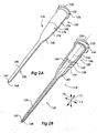
Referring now to Figure 2A, another embodiment of the catheter assembly 110 of the
invention is shown. This embodiment of the catheter assembly 110 of the invention includes
at least two integrally-formed components, and thus may be constructed of more than one
material. Specifically, the catheter assembly 110 includes a hub portion 120 and a catheter
portion 150 which merge at a joint 152. In this embodiment of the catheter assembly 110, the
hub portion 120 includes a hub base 132 including luer threads 133, a hub barrel 126 attached
to the hub base, and a hub adapter (not shown) that interfaces with the catheter portion 150 of
the assembly 110. The catheter portion 150 includes a tip 162, a catheter cannula 156, a
transition region 142, and an attachment sleeve 174.
As above, the hub portion 120 may include a gate region 134. In other embodiments
of the catheter assembly 110, the hub 120 includes two or more such gate regions 134. In this
embodiment, the gate region 34 is shown positioned on the hub base 132 of the assembly 110.
The catheter portion 150 of the catheter assembly 110 may also include a gate region 176 on
its surface. In some embodiments, the gate region 176 may be positioned on the attachment
sleeve 174 of the catheter region 150, as shown in Figure 2A. In other embodiments, the gate
region 176 may be positioned on the transition region, or alternatively, on the catheter cannula
156.
The joint 152 of the catheter assembly 110 is shown in cross-sectional detail in Figure
2B. In the catheter assembly 110, the catheter portion 150 attaches to the hub portion 120 via
the attachment sleeve 174 extending from the transition region 142 of the catheter portion
150. As seen in Figure 2B, the attachment sleeve 174 projects outwardly from the transition
region 142 of the catheter portion 150. The attachment sleeve 174 has a geometry configured
to surround and interface with the hub adapter 138 of the hub portion 120 of the assembly 110
to provide attachment at the joint 152 in a substantially sealed manner. This sealed
attachment at the joint 152 may be provided in a variety of ways.
The joint 152 may be produced relying upon a variety of factors to produce a strong,
sealed joint 152. First, the materials used to produce the hub and catheter portions 120, 150
may be selected such that the materials will adhere to each other during the manufacturing
process. Examples of materials having suitable characteristics will be discussed in greater
detail below. As discussed briefly above, the materials selected for the hub and catheter
portions 120, 150 may be selected to give each individual portion a physical property that
may be desirable. In some embodiments, it may be desirable to produce the hub portion 120
out of a material demonstrating rigidity to assist in attaching the assembly 110 to other
equipment. In addition, in some embodiments, it may be desirable to produce the catheter
portion 150 out of a substantially flexible material to allow insertion and use of the catheter
150 without damage to the catheter 150 or injury to the circulatory system of the patient.
As above, the catheter assembly 110 may be designed and produced such that the hub
portion 120 and the catheter portion 150 both include at least a slight draft angle, so that the
hub portion 120 and the catheter portion 150 are each slightly wider at their proximal ends
than at their distal ends. This draft angle may be varied to aid in steps of the production of the
catheter assembly 110, including removal of the finished product from a mold.
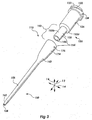
Referring now to Figure 3, an exploded view of the catheter assembly 110 of Figures
2A and 2B is shown. Specifically, Figure 3 shows the catheter assembly 110 separated along
the interface 154 of the joint 152 of the hub portion 120 and the catheter portion 150 of the
assembly 110 of Figures 2A, 2B. Figure 3 illustrates the conformation of the surfaces of the
hub adapter 138 and the attachment sleeve 174 that form the interface 154 of the joint 152.
The strength of the joint 152 of the catheter assembly 110 of Figure 3 may be
modulated by varying the size of the interface 154 of surfaces of the catheter portion 150 and
the hub portion 120 of the catheter assembly 110. In embodiments using materials which
adhere to each other during the manufacturing process, increasing the surface area of the
interface 154 of the joint 152 increases the strength of the joint 152. Thus, in the catheter
assembly 110, the length of the attachment sleeve 174 and the length of the corresponding
hub adapter 138 may be varied to change the total surface area of the interface 154. This, in
turn, varies the strength of the resulting joint 152.
The interface 154 of the joint 152 of the catheter assembly 110 may be configured to
provide a tensile strength zone 155a and a shear strength zone 155b. Specifically, the tensile
strength zone 155a may be defined as the surface area of the ring shown at the interface 154.
This surface area may be varied by extending or reducing the radii of the interior and exterior
of the hub portion 120. When the hub 120 and the catheter 150 are made of compounds
which chemically bond, e.g. via electrostatic bonds, van der Waals interactions, or other
chemical interactions or bonds; or when the hub 120 and catheter 150 are made of compounds
such as polymers which my physically entangle, this may increase or reduce the tensile
strength of the joint 152.
The shear strength zone 155b is the surface area of the sleeve projecting in a
longitudinal direction 12 from the tensile strength zone 155a. The area of the shear strength
zone 155b may similarly be varied by extending the longitudinal length of the shear strength
zone 155b, or by expanding its radius. When the hub 120 and the catheter portion 150 are
made of compounds which bond in any of the manners described above, this may increase or
decrease the strength of the joint 152. These principles may be applied in many of the
embodiments of the two-piece integrated catheter assemblies of the invention to provide
adequate tensile and shear strength with various pairs of compounds used to form the
individual components of the catheter assembly 110.
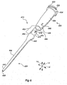
Figure 4 shows an exploded perspective view of additional embodiment of a catheter
assembly 210 of the invention. Similar to the assembly 110 of Figures 2A-3, the embodiment
of Figure 4 includes a hub portion 220 and a catheter portion 250. The hub portion 220
includes a hub base 232 which may include luer threads 233 to allow locking the assembly
210 to a compatible device in a fluid-sealed manner. The hub portion 220 further includes a
hub barrel 226 extending from the hub base 232. In this embodiment, the hub barrel 226
terminates in a hub adapter face 238. The hub 220 further includes a gate region 234
positioned on the luer threads 233 of the hub base 234. In use, the hub adapter face 238 is
attached to the catheter portion 250 of the assembly 210.
The catheter portion 250 of the assembly 210 has a catheter attachment face 274
configured to be joined to the hub adapter face 238. The catheter portion 250 further includes
a gate region 276 positioned on the transition region 242. In this embodiment of the assembly
210, the attachment of the catheter attachment face 274 and the hub adapter face 238 forms a
butt-joint 252. In this embodiment of the catheter assembly 210, the butt joint 252 includes
an interface 254 having a surface area which may be smaller than that of the catheter
assembly 110 of Figures 2A-3. In embodiments of the invention such as the assembly 210
shown in Figure 4, the strength of the joint 252 formed between the hub portion 220 and the
catheter portion 250 is dependent on the strength of the bond formed between the materials
used to produce the specific portions 220, 250. Indeed, the materials used to produce the
specific portions 220, 250 may be selected for the strength of the bond they form since the
surface area of the interface 254 may be much lower than that of the surface area of the
interface of the assembly 110 of Figures 2A-3.
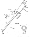
Referring now to Figure 5A, yet another embodiment of a catheter assembly 310 of
the invention is shown in an exploded perspective view. The catheter assembly 310 includes
a hub portion 320 and a catheter portion 350. The hub portion 320 includes a hub base 332
which may include luer threads 333 to allow locking the assembly 310 to a compatible device
in a fluid-sealed manner. The hub portion 320 further includes a hub barrel 326 extending in
a longitudinal direction 12 from the hub base 332. The hub barrel 326 includes a gate region
334. The hub barrel 326 terminates in a hub adapter face 338. In use, the hub adapter face
338 is attached to the catheter portion 350 of the assembly 310. The catheter portion 350 of
the assembly 310 includes an attachment sleeve 374 extending from the transition region 342,
and a catheter cannula 356 terminating in a tip 362. The catheter portion 350 also includes a
gate region 376, positioned on the transition region 342. The catheter portion 350 also has a
lumen 368 which is continuous with the lumen 346 of the hub portion 320 of the catheter
assembly 310 when assembled.
The hub adapter face 338 of the catheter assembly 310 is configured as an internal
interlock sleeve joint to allow use of a relatively short attachment sleeve 374. Despite their
short length, the hub adapter face 338 and the attachment sleeve 374 form an interface 354
having a relatively large surface area because both the inward-facing and outward-facing
surfaces of the attachment sleeve 374 interface with the hub adapter face 338. Various other
structural conformations of the attachment sleeve 374 and the hub adapter 338 may be used
within the scope of the invention to provide a large surface area for the interface 354 of the
joint 352.
Referring now to Figure 5B, an end view of the hub 320 taken from line 5B-5B is
shown. This end view shows the hub adapter face 338 of the catheter assembly 310. This
hub adapter face 338 includes an interface 354. The hub lumen 346 is also shown. In Figure
5B, the interface 354 is an annular groove configured to receive the attachment sleeve 374
shown in Figure 5A.
The strength of the joints 152, 252, 352 of embodiments of the invention shown in
Figures 2 through 5B may be further modified by incorporating features into the interfaces
154, 254, 354 which provide a mechanical interlock. Such mechanically-interlocking features
may be provided alone, or may be provided to enhance the strength of chemical bonds formed
between the materials at the joint 152, 252, and 352. One such embodiment of a catheter
assembly 410 that includes a mechanical interlock is shown in Figure 6.
Referring now to Figure 6, another catheter assembly 410 according to the invention is
shown. The catheter assembly 410 again includes a hub portion 420 and a catheter portion
450. The hub portion 420 includes a hub base 432 which may include luer threads 433 to
allow locking the assembly 410 to a compatible device in a fluid-sealed manner. The hub
base 432 further includes a gate portion 434. The hub portion 420 further includes a hub
barrel 426 extending from the hub base 432. The hub barrel 426 terminates in a hub adapter
438. The hub adapter 438 here includes a locking orifice 440 which integrates with the
catheter portion 450.
The catheter portion 450 of the assembly 410 includes an attachment sleeve 474
extending from the transition region 442. In this embodiment, the attachment sleeve 474
includes a gate region 476. The catheter assembly 410 of Figure 6 shows one version of a
joint 452 which utilizes a mechanical interlock. In this embodiment of the catheter assembly
410, the attachment sleeve 474 includes an attachment lock 478 in the form of a raised peg
478 configured to pass through the locking orifice 440 of the hub adapter 438. The gate
region 476 may be positioned on the mechanical interlock 478 as shown in Figure 6, or may
be located on other regions of the catheter portion 450 to ease manufacturing of the assembly
410. The positioning of the attachment lock 478 through the locking orifice 440 as the lock
478 is produced provides a mechanical interlock. Thus, the interface 454 between the hub
portion 420 and the catheter portion 450 is adapted to provide a more strong attachment.
As in previous embodiments, the catheter portion 450 of the assembly 410 further
includes a catheter cannula 456, also extending from the transition region 442, which
terminates in a tip 462. The catheter portion 450 also has a lumen 468 which is continuous
with the lumen 446 of the hub portion 420 of the catheter assembly 410 when assembled.
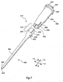
Referring next to Figure 7, yet another catheter assembly 510 of the invention is
shown. The catheter assembly 510 includes a hub portion 520 and a catheter portion 550.
The hub portion 520 includes a hub base 532 which may include luer threads 533 to allow
locking the assembly 510 to a compatible device in a fluid-sealed manner. The hub base 532
here further includes two gate regions 534 (only one of which is visible). The hub portion
520 further includes a hub barrel 526 extending from the hub base 532. The hub barrel 526
terminates in a hub adapter 538. The hub adapter 538 here includes a locking slot 540 which
integrates with the catheter portion 550.
The catheter portion 550 of the assembly 510 includes an attachment sleeve 574
extending from the transition region 542. The catheter portion 550 here includes two gate
regions 576 (only one of which is visible) which resulted from the production methods used to
produce in the assembly 510. The catheter assembly 510 of Figure 7 shows another version
of a joint 552 which utilizes a mechanical interlock to provide strength to the joint 552. In
this embodiment of the catheter assembly 510, the attachment sleeve 574 includes an
attachment ridge 578 configured to fit in the locking slot 540 of the hub adapter 538. The fit
of the attachment ridge 578 into the locking orifice 540 provides a mechanical interlock.
Referring next to Figure 8A, yet another catheter assembly 910 of the invention is
shown in a perspective view. This catheter assembly 910 is a multi-component catheter
assembly comprising a hub portion 920, a flexible pivot portion 980, and a catheter portion
950. The hub portion 920 includes a hub base 932 which may include luer threads 933 to
allow locking the assembly 910 to a compatible device in a fluid-sealed manner. The hub
base 932 here further includes two gate regions 934 (only one of which is visible). The hub
portion 920 further includes a hub barrel 926 extending from the hub base 932. The catheter
portion 950 of the assembly 910 includes a transition region 942. The catheter portion 950
here includes two gate regions 976 (only one of which is visible) which resulted from the
production methods used to produce in the assembly 910.
In this embodiment of the catheter assemblies of the invention, the catheter assembly
910 further comprises a flexible pivot portion 980. The flexible pivot 980 is positioned
between the hub 920 and the catheter 950 and interfaces with them at joints 952a, 952b. The
flexible pivot 980 is configured to allow manipulation and movement of the hub portion 920
of the catheter assembly 910 while minimizing disturbance or displacement of the catheter
portion 950 of the catheter assembly 910.
In the catheter assembly 910 of Figure 8A, the flexible pivot 980 includes ridges 982.
These ridges 982 act as accordion-pleats to allow easy bending of the pivot 980. In addition,
as discussed in greater detail below, the pivot portion 980 may be produced of a material
which is flexible and resilient in order to allow bending and return to its original shape. The
provision of the flexible pivot 980 to the catheter assemblies of the invention allows
placement of the catheter portion 950 of the assembly 910 and subsequent manipulation of the
hub portion 920 without disturbing the placement of the catheter portion 950 in a patient.
Figure 8B shows a partially-cut-away perspective view of the catheter assembly 910
of Figure 8A. As above, the assembly 910 includes a hub portion 910, a catheter portion 950,
and a flexible pivot 980. In Figure 8B, the assembly is shown partially cut away to reveal the
lumen 946 of the hub portion 920 and the lumen 968 of the catheter portion 950. Figure 8B
also demonstrates one possible configuration of the joints 952a, 952b linking the hub 920 and
the catheter 950 to the flexible pivot 980. As previously discussed, the joints 952a, 952b may
simply rely on the bonding properties of the materials used to form each of the segments 920,
950, 980 of the catheter assembly 910.
The three-component configuration of the catheter assembly 910 adds further
flexibility in the design of the catheter assemblies of the invention. Specifically, in the two- component
assemblies 110, 210, 310, 410, and 510 discussed previously, the materials of the
hub and catheter portions were generally selected for their ability to bind to each other. In the
three-component configuration of the catheter assembly 910, the materials of the hub 920 and
catheter 950 may not bond well to each other, but may instead bond well to the material used
to form the flexible pivot 980 of the assembly 910.
The pivot 980 of the catheter assembly 910 of Figure 8B is joined to the hub 920 and
catheter 950 portions of the assembly 190 at joints 952a, 952b. Each of these joints 952a,
952b relies on the bonding of the materials at interfaces 954a, 954b, and on a mechanical
interlock. More specifically, each of the joints 952a, 952b, comprises a circumferential rib
957a, 957b. The joint 952a is formed by a hub adapter 938 interfacing at 954a with a first
pivot attachment 986a. At joint 952a, the hub adapter 938 comprises a circumferential rib
957a which is received by the pivot attachment 986a. The joint 952b is formed by an
attachment sleeve 974 interfacing at 954b with a second pivot attachment 986b. At joint
952b, the second pivot attachment 986b comprises a circumferential rib 957b which is
received by the attachment sleeve 974.
As discussed previously, the size and geometry of the interfaces 954a, 954b may be
varied to vary the strength of the bond. In addition, the specific type of mechanical interlock
used in catheter assemblies such as 410, 510, and 910 may be varied by one of skill in the art.
Those of skill in the art will recognize that numerous other catheter assemblies may be made
within the scope of the present invention.
Various materials have been tested for suitability for use in producing the catheter
assemblies of the invention. Several components have been tested for use in producing the
single-part, single-material catheter assemblies such as 10, and the catheter portions of multi-part
catheter assemblies such as 110, 210, 310, 410, 510, and 910. These complete catheter
assemblies and catheter portions have been produced of polyurethane materials. In specific
embodiments of the catheter assemblies of the invention, a low viscosity polyurethane is
desirable. In some specific embodiments of the invention, a proprietary polyurethane
Vialon™ is used.
Vialon™ is a polyurethane biomaterial used in catheter products. Vialon™ may be
molded to produce a smooth surface which reduces catheter drag during insertion and
prevents catheter-related thrombosis during use as an indwelling catheter device. Catheter
products produced with Vialon™ soften after insertion into the circulatory system of a patient,
allowing the catheter to better conform to the natural shape and form of the blood vessel into
which it has been inserted. This helps to reduce injury to or irritation of the lining of the
vessel.
In specific embodiments of the invention, the catheter portion 150 is produced using
Vialon™ modified to reduce its viscosity. The process used to modify the viscosity of the
Vialon™ may include reducing the molecular weight of the Vialon™ using multiple: pass
extrusion.
Other materials are also suitable for use in producing the single-part single-material
catheter assemblies (such as 10 of Figure 1), and the catheter portions of multi-part catheter
assemblies such as 110, 210, 310, 410, 510, 910. Suitable materials include polyurethane
elastomer, polyester, polyethylene, polypropylene, polybutylene, polytetrafluoroethylene,
fluorinated ethylene-propylene copolymer, silicone, polyether block amides ("PEBAX"), and
poly vinyl chloride.
Several materials have been tested for use in the hub and catheter portions of the
catheter assemblies (such as 110, 210, 310, 410, 510, and 910) of the invention. In some
embodiments, the hub portion has been produced of polycarbonate and polyurethane
materials. In addition to these materials, however, PET, nylon 12 homopolymer, and nylon
12 copolymer have been tested. The resulting experimental data indicates that they would be
suitable for use in producing the catheter hub 120 of the assemblies 110 of the invention.
Specifically, such materials provide a relatively rigid base to allow for secure attachment of
the assembly 110 to outside apparatus.
In addition to the above materials, other materials have been tested for use in the hub
and catheter portions of the catheter assemblies (such as 110, 210, 310, 410, 510, and 910) of
the invention. In some embodiments, the hub portion may be produced of materials such as
nylon, polymethyl-methyacrylate, polyester, acrylo-nitrile butadiene styrene, polyurethane,
polyethylene, polypropylene, polyether block amides ("PEBAX"), poly vinyl chloride,
polycarbonate, acrylic, polystyrene, and polymethylpentene.
The catheter assemblies of the invention may alternatively be produced using reaction
injection molding technologies, in which prepolymers are injected into the mold instead of
using molten polymeric materials. After injection, the prepolymers polymerize and cure to
form the completed catheter assemblies of the invention. Reaction injection molding
processes often operate at temperatures lower than those required for traditional injection
molding technologies. This may also reduce the energy expenditures required to produce the
catheter assemblies of the invention. In addition, since prepolymers are generally less viscous
than molten polymers, they may flow more easily into molds, reducing tooling costs. This
may make reaction injection molding useful in catheter assembly designs using complex
joints or tip geometries. Reaction injection molding cycle times are also generally short,
resulting in cycle times of less than about one minute. Materials suitable in reaction injection
molding methods generally include polyurethanes, nylons, and other fast-reacting
prepolymers. Generally, amine-extended polymers form more quickly, while diols may
require up to 60 seconds for sufficient polymerization.
Material bond strength studies were conducted using various combinations of several
of the above-listed materials to produce catheter assemblies according to the catheter design
of Figure 4, having a relatively small interface area. In these studies, the predicted loads for
failure of a catheter constructed using the following adapter materials and either clear or filled
Vialon™ were determined. These predicted failure loads are shown in Table 1 below:
| TABLE 1 | Predicted Load for Failure of Adapter/Tube Interface (1b) End-joint Design |
| Adapter Material | Clear VialonTM | Filled Vialon ™ |
| PET |
| | 10 | 6.8 |
| Polycarbonate (Lipid Resistant) | 13 | 4.0 |
| Polycarbonate | 35 | No data available |
| Isoplast | 38 | 25 |
| Nylon 12 Homopolymer | 33 | 30 |
| Nylon 12 Copolymer | No joint failure | 17 |
Although predicted failure loads for the first two materials appear less favorable,
catheter designs providing a larger interface/contact area may likely be suitable. In addition,
it is believed that Vialon™ having less of the radiopaque compound (here barium sulfate),
and thus, adhesion will be improved.
Additional data were obtained from materials testing studies. The data obtained is
shown in Table 2 below.
| TABLE 2 | Stress at Failure (psi) |
| Adapter Material | Clear Vialon | Filled Vialon |
| PET | 646 | 436 |
| Polycarbonate (Lipid Resistant) | 804 | 251 |
| Polycarbonate | 2260 | No data available |
| Isoplast | 2450 | 1581 |
| Nylon 12 Homopolymer | 2090 | 1930 |
| Nylon 12 Copolymer | No joint failure | 1080 |
In these materials testing studies, catheters were produced with either Vialon™ or Vialon™
including a radiopaque compound, referred to herein as "filled VialonTM" and a second
adapter material. These catheters were then subjected to pull-testing to test adhesion quality.
It is believed that the stess at failure exhibits sufficient adhesion to resist a 3-pound pullout
force.
The following discussion returns to the catheter assembly 10 of Figure 1 to describe
example of methods by which the catheter assemblies of the invention may be produced. In a
first set of methods, the catheter assembly 10 may be produced using injection molding.
Referring now to Figure 9A, a mold is shown for producing single-component, single-material
catheter assemblies of the invention such as catheter assembly 10 of Figure 1. The
catheter assembly 10 of Figure 1 may be manufactured in a "one step" fashion. In this
application, the term "one step" in the context of manufacturing refers to a process of
completely forming an item in a substantially final, usable condition, with a single
manufacturing process. Manufacturing processes such as injection molding may, itself, have
several discrete steps, however, if operations such as core pin tensioning, "tipping" (insertion
of the tip into a specialized tip mold or other processing of the completed catheter assembly to
provide a catheter with an acceptable tip geometry), part attachment, or other secondary
molding steps are avoided, the process is still referred to herein as a "one step" process.
Referring now to Figure 9A, one embodiment of a mold 610 capable of molding the
catheter assembly 10 of Figure 1 in a one step manner is shown. The mold 610 may be used
or adapted for use with a wide variety of injection molding machines. Suitable injection
molding machines used with the mold 610 are capable of providing rapid and accurate
acceleration and deceleration of a selected molten plastic into the mold 610 to ensure that the
mold 610 is properly filled. Further, suitable injection molding machines are generally
capable of doing this rapidly and repeatedly while exhibiting consistent performance in each
iteration of the manufacturing process. The injection molding machine has been omitted from
Figure 9A for clarity.
The mold 610 may have an A-side 612 that may be coupled to an injection nozzle of
the injection molding machine. In embodiments in which the nozzle is coupled to the A-side
612, the nozzle is attached so as to be continuous with an orifice 650a configured to receive
molten plastic. The molten plastic may then be channeled to the cavities 660 of the A-side
612 via a region 650b continuous with the orifice 650a which directs the molten plastic to
runner pathways 648. The mold 610 is configured to receive molten plastic from such a
nozzle. The mold 610 may also have a B-side 614 that is configured to translate with respect
to the A-side 612.
The B-side 614 of the mold 610 may have a floating plate 624 slidably mounted with
respect to a base plate 622. The base plate 622 may remain fixed in place, while the floating
plate 624 may be configured to move a limited distance away from the base plate 622. The
motion of the floating plate 624 with respect to the base plate 622 may be used to help remove
a completed catheter assembly (not shown) from the mold 610. The base plate 622 may be
configured to retain core pins 640 which may travel through the floating plate 624 and extend
from the B-side 614 of the mold 610 into the A-side 612 of the mold 610 when the sides 612,
614 are mated for use. The floating plate 624 may additionally include runner paths 648
traveling away from a point 650b at which the runner paths 648 interface with the orifice 650a
when the mold 610 is assembled. The floating plate 624 may further include core pins 640
extending from the base plate 622 through the floating plate 624. The floating plate 624 may
additionally include a plate seal 632 to isolate the center of the mold 610 where the actual
molding occurs.
The B-side 614 of the mold 610 may be configured to translate relative to the A-side
612 to allow selective mating or disengagement of the sides 612, 614. The A-side 612 may
include a cavity plate 626. The A-side 612 of the mold 610 includes individual cavities 660
which receive the core pins 640 and leave space for receiving the molten plastic that defines
the shape of the one-piece catheter assembly produced by the mold 610. In addition, the
cavity plate 626 may include alignment bores 618 for receiving the pins 616 extending from
the B-side 614 of the mold 610. One of ordinary skill in the art will add additional plates if
needed to provide or support components of the mold such as the core pins, or to add
components such as ejector pins.
The orientation of the A-side 612 and the B-side 614 of the mold 610 may be
stabilized by a set of leader pins 616 extending from either the floating plate 624 or the base
plate 622. The leader pins 616 are configured to pass through alignment bores 618 present in
plates such as the floating plate 624 (if mounted to the base plate 622), or the cavity plate 626.
These pins 616 stabilize the mold 610 to provide proper alignment of the individual plates
622, 624, and 626. In addition, the pins 616 allow translation of the individual plates 622,
624, and 626 relative to each other.
In use, the floating plate 624 is mated to the cavity plate 626 such that the cavities 660
define the space needed to produce the catheter assembly. The nozzle of an injection molding
machine is attached to the cavity plate 626 having an orifice 650a. The injection molding
machine injects molten plastic into the mold. For purposes of this discussion, the nozzle is
connected to the orifice 650a of the cavity plate 626, and injects molten plastic into the orifice
650a. Having traveled through the orifice 650a, the molten plastic emerges on the surface of
the floating plate 624. The molten plastic then travels across the floating plate 624 along
runner pathways 648. The runner pathways 648 convey the molten plastic toward the core
pins 640 and the cavities 660.
Referring now to Figure 9B, a partial plan view of the mold of Figure 9A is shown
taken at the line 9B-9B of Figure 9A. Figure 9B shows the runner pathways 648 in detail.
The runner pathways 648 may simply take the form of slots in the floating plate 624 of Figure
8A. As shown in Figure 9B, the runner pathways 648 may be substantially symmetrical, so
that they can convey simultaneous flows of molten plastic toward the core pins 640 and the
cavity 660. Similarly, the runner pathways 648 may open to the orifice 650A shown on
Figure 9A at a region 650b configured to correspond to the orifice 650a with an orifice that
may be of the same size. In addition, the runner pathways 648 may have the same length and
cross sectional area. These characteristics help to provide uniform flows of molten plastic to
the cavities 660.
One of skill in the art would understand that the runner pathways 648 shown in Figure
9B may be varied within the scope of the invention, and that in addition, alternate molding
technologies may be used to produce the single-part and multi-part catheter assemblies of the
invention without producing runners. In some specific examples, hot- and semi-hot-runner
systems may be used with molds within the scope of the invention to produce the catheter
assemblies of the invention. Such technologies often allow supply of molten plastic directly
or near-directly to the mold cavity without utilizing a runner system. This avoids production
of waste product and often shortens production cycle time.
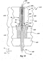
Referring now to Figure 10, a partial cross-sectional view of the mold 610 of Figure
9A is shown. In this Figure, the mold 610 has been assembled and injected with a suitable
material as described above to form the single-material catheter assembly 10, and the catheter
assembly 10 has been formed. As described above, the mold 610 includes an A-side 612 and
a B-side 614 which are shown mated for use. In this Figure, the B-side 614 is shown to
include a floating plate 624 and a base plate 622. In alternate embodiments of the mold 610,
features and components of the A-side 612 and the B-side 614 may be exchanged. In
addition, additional plates and components may be included as needed on either or both sides
in order to support alternative catheter assembly 10 geometries, enhance use of the mold 610,
and in some cases, to aid in ejection of the completed catheter assembly 10. The A-side 612
of the mold 610 is shown to include a cavity plate 626. In alternate embodiments of the mold
610, additional plates and components may be included as needed.
The cavity plate of the A-side 612 of the mold 610 includes a cavity 660 having a hub
cavity region 662 and a catheter cavity region 664. During use, a core pin 640 may extend
from the B-side 614 of the mold 610 into the hub cavity region 662, and then into the catheter
cavity region 664. The core pin 640 defines the lumen of the resulting catheter assembly 10.
In Figure 10, the core pin 640 is anchored to a proximal anchor 642 and a pilot 629. The
proximal anchor 642 may be attached to the base plate 622 or to an assembly external to the
mold 610 as shown in Figure 10. The pilot 629 attached to the distal end of the core pin 640
may be anchored to the cavity plate 626, or alternatively to an assembly outside of the mold
610 as shown in Figure 10.
The core pin 640 extends from the floating plate 624 into the cavity 660 of the cavity
plate 626 in a manner such that molten plastic is unable to escape from the cavity 660. The
core pin 640 may even extend from the floating plate 624 in an airtight manner, if desired.
Alternatively, the core pin 640 and the floating plate may be made to fit together such that air
is able to pass between them to exit the cavity 660.
In some embodiments, it will be desirable to apply a vacuum to the cavity 660 prior to
injection of molten plastic into the cavity 660. This evacuates air from the cavity 660 to allow
the molten plastic to entirely fill the cavity 660. The cavity plate 626 may thus include a
vacuum channel 644 accessible from outside the mold 610. Vacuum fittings (not shown) may
be attached to such a vacuum channel to draw air out of the cavity 660. If desired, the core
pin 640 or pilot 629 may even be made slightly porous to expedite the expulsion of air from
the cavity 660. The vacuum fitting may be coupled to a vacuum source, such as a vacuum
pump, as is known in the art. In each of these situations, however, the core pin 640 is able to
slide relatively freely through the floating plate 624 into the cavity 660 of the cavity plate 626.
In some embodiments of the mold 610 of the invention, it may be desirable to provide
mold components which may be rapidly and inexpensively replaced in order to speed repairs
and reduce repair costs. Thus, in some embodiments, the mold 610 may include modular
blocks such as a taper lock stripper block 628, a modular pilot block 629, and a modular
catheter block 630. These modular blocks 628, 629, 630 are mounted such that they are
positioned in the appropriate plates 622, 624, 626 of the mold 610. One such mounting
configuration of the modular blocks 628, 629, and 630 is shown in Figure 10. These modular
blocks 628, 629, and 630 may permit rapid modification, repair, or replacement of various
components of the floating plate 624, as well as the possibility of using the mold 610 to
produce parts having different configurations. In one example, components of the mold 610
could be replaced to allow production of catheters of different sizes.
In one example, catheter block 630 may be substituted to allow the production of a
catheter with a different length or width. The modular pilot block 629 may also be substituted
to allow variation of the tip geometry of the catheter assembly produced by the mold. These
modular blocks may be produced using methods known to one of ordinary skill in the art.
The methods of the invention allow production of catheter assemblies having tip geometries
equivalent to those previously produced using secondary tip processing methods.
The mold 610 may further include components to assist in the removal of the catheter
assembly 10 from the mold 610, as well as components configured to remove any runner 648
formed during the process. Such removal methods include manual removal; mechanical
removal by ejector pins, stripper plates, or robotic removal; or using other equipment and
techniques known to one of ordinary skill in the art.
The hub and catheter cavity portions 662, 664 of the mold 610 form a cavity 660 into
which a molten plastic may be injected. As illustrated in Figure 9B, in some embodiments of
the mold 610 and methods of the invention, molten plastic is introduced into the cavity 660
via runners 648 which deliver molten plastic to at least two separate gate regions (not shown)
of the cavity 660. This provides multiple flows of molten plastic into the cavity 660 in an
even manner. These even flows may provide a high degree of molecular alignment in the
longitudinal direction 12. In addition, the evenness of the flows may help to prevent
deflection of the core pin 640.
In a next example, the invention further provides methods and apparatus for producing
multi-part, and potentially multi-material integrated catheter assemblies. The following
discussion proceeds with reference to the catheter assembly 110 of Figures 2A-3. One of
ordinary skill in the art would be able to adapt this method to produce the catheter assemblies
of the invention.
In many of these methods of the invention, either the catheter portion 150 or the hub
portion 120 of the assembly 110 is first injection molded, and then in a subsequent step, the
remaining component is overmolded onto the previously produced part. In the method of the
invention illustrated in Figures 11-15, a sequential overmolding method is used in which the
hub of a catheter assembly of the invention is molded in a first mold, removed from the first
mold, inserted into a second mold, and overmolded with a catheter. One of ordinary skill in
the art would understand that the method could be easily adapted to reverse the order in which
the components are produced to produce the catheter portion first, and then to overmold the
hub portion about it.
In addition to the above, in alternate embodiments of the invention, the overmolding
process may be completed in a single mold which makes use of replaceable or rotating cores,
rotating cavities on plates, or other similar technologies known to one of skill in the art in
order to allow sequential production of the two components within a single mold. One mold
suitable of functioning in such a fashion is shown in Figure 16. In still other embodiments of
the invention, injection molding technologies may be utilized which allow injection of two or
more molten plastics either simultaneously or in rapid succession. Other variations on these
production methods that are understood by one of ordinary skill in the art are also included in
the scope of the invention.
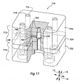
Referring first to Figure 11, a mold of the invention for use in sequential overmolding
methods used to produce a multi-part integrated catheter assembly is shown. More
specifically, a first mold 710 is shown for use in the production of an integrated two-piece
catheter assembly of the invention such as catheter assembly 110 of Figures 2A-3. Figure 11
illustrates the configuration of a mold 710 configured to produce the hub portion 120 of the
catheter assembly 110 of Figures 2A-3. This mold is used in the initial steps of a method for
producing integrated two-piece catheters according to the invention to produce a hub portion
120 of the catheter assembly 110. According to the method, the hub portion 120 of the
assembly 110 is first produced in a mold such as 710, and then the catheter portion 150 is
overmolded onto the hub portion 120 to produce the final catheter assembly 110. One of
ordinary skill in the art would understand that according to the methods of the invention, the
mold 710 could instead be configured to produce the catheter portion 150 of the assembly
110, and that subsequently, the hub portion 120 could be molded thereto. In addition, one of
skill in the art would understand that the mold and associated method could be modified to
produce catheter assemblies including more than two components such as catheter assembly
910 of Figures 8A-8B.
The mold 710 includes an A-side 712 and a B-side 714 which mate as shown to
provide a cavity 760 for injection molding a catheter hub portion. The B-side 714 includes a
base plate 722, and a floating plate 724, while the A-side 712 includes a cavity plate 726.
Other plates may be used in molds of the invention, as known in the art and described above,
to add function to the mold. The plates 722, 724, 726 are aligned using leader pins 716 which
extend from the base plate 722 through alignment bores 718 in the floating plate 724 and the
cavity plate 726. In many embodiments of the mold 710 of the invention, the plates 724, 726
are slidable along the leader pins 716 such that the floating and cavity plates 724, 726 may be
mated and separated during the steps of the method of the invention to provide a cavity 760
prior to injection of molten plastic, and then to allow removal of a molded component.
To produce a catheter hub 120 as shown in Figures 2A-3, the mold 710 of Figure 11
may further include a core pin (here omitted for clarity) which may extend from the B-side
714 of the mold 710 and project into the cavity 760 of the A-side 712. The core pin 740
projects into a cavity 760 of the cavity plate 726 and combines with the cavity 760 to define
the shape of the component produced. The cavity 760 interfaces with a runner pathway 748 at
a gate region 752. In this embodiment of the mold 710, a single gate region 752 is used. In
alternate embodiments, multiple gate regions 752 may be used in order to vary the number of
flows of plastic and to reduce the potential for deflection of the core pin 740 upon injection of
molten plastic as discussed above. The runner pathway 748 exits the mold 710 at a sprue
orifice 750. It is through this sprue orifice 750 that molten plastic is injected according to the
method of the invention to produce the final molded part.
Referring now to Figure 12, an exploded perspective view of the mold 710 of Figure
11 is shown. Here, the B-side 714 is shown exploded, with the floating plate 724 shown to
have translated in a longitudinal direction 12 along the leader pins 716. As above, the leader
pins 716 are shown to pass through the floating plate 724 in alignment bores 718. Figure 12
further shows the A-side 712, including the cavity plate 726 detached from the mold 710. As
shown, the floating plate 724 further contains a core pin orifice 772 through which the core
pin 740 passes. The core pin 740 is shaped to define the lumen 146 of the catheter hub 120 of
Figures 2A-3. Figure 12 further shows a catheter hub 120 according to the invention, shown
ejected from the mold 710. The cavity plate 726 includes alignment bores 718 and is slidable
along the leader pins 716 when attached to the B-side 714 of the mold 710.
Referring now to Figure 13, a catheter overmold 810 is shown. In Figure 13, portions
of the overmold 810 have been cut away for clarity. The catheter overmold 810 is used in the
steps of the method of the invention to produce two-piece integrated catheter assemblies such
as 110 shown in Figures 2A-3. The overmold 810 includes a base plate 822, a floating plate
824, and a cavity plate 826. The overmold 810 is shown open, with the A-side 812 separate
from the B-side 814.
The overmold 810 includes a cavity 860 including a hub cavity portion 862 and a
catheter cavity portion 864. The hub cavity portion 862 is generally positioned in the cavity
plate 826. According to variations of the method of the invention, the two-piece integrated
catheter assemblies of the invention may be produced by first molding the catheter hub 120
and then using an overmold such as 810 to integrally mold a catheter portion to the hub 120.
Thus, in Figure 13, the overmold 810 is shown to include a catheter hub 120 molded using the
initial steps of the method of the invention. Specifically, the catheter hub 120 has been
molded, and then inserted into the hub cavity portion 862 of the cavity 860 of the overmold
810. As discussed above, one of ordinary skill in the art would understand that the order of
molding could be varied. In addition, one of skill in the art would understand that the
geometry of the catheter hub of the invention may be varied as taught above with reference to
catheter assemblies 210, 310, 410, 510, and 910 of Figures 4-8.
With the catheter hub 120 placed in the hub cavity portion 862, the hub adapter
portion 138 of the catheter hub 120 may be configured to extend into the catheter cavity
portion 864 of the overmold 810 such that when the catheter portion 150 is molded about the
hub portion 120, a secure joint 152 is formed. As discussed above, such a joint 152 may be
formed simply by providing an adequate interface between the two portions 120, 150 of the
catheter assembly 110 to allow the materials of the hub portion 120 and the catheter portion
150 to adhere. In addition, in some embodiments such as catheter assemblies 410 and 510 of
Figures 6 and 7, it may be desirable to form a mechanical interlock. In either of these
situations, the hub portion 120 extends into the catheter cavity portion 864. Those portions of
the hub 120 which are present in the catheter cavity portion 864 of the cavity 860 may be
directly overmolded with the molten plastic used to form the catheter portion of the catheter
assembly.
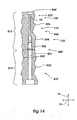
Referring now to Figure 14, the overmold 810 of Figure 13 is shown with the A-side
812 mated with the B-side 814 and with a catheter assembly 110 completely formed within.
More specifically, the base plate 822 with the core pin 840 extending from it has been inserted
into the cavity 860. As noted previously, the cavity 860 includes a hub cavity portion 862 and
a catheter cavity portion 864. Prior to uniting the A-side 812 and the B-side 814, the pre-molded
catheter hub 120 is inserted into the hub cavity portion 862 of the floating plate 824.
The core pin 840 is configured to travel through the pre-molded catheter hub 120 to a specific
point, at which the core pin 840 fits the hub 120 in a sealed manner such that when molten
plastic is injected into the cavity 860, it is substantially directed into the catheter cavity
portion 864.
The core pin 840 may be anchored to the base plate 822 in a variety of ways. In
Figure 14, the attachment has been omitted for clarity. In some embodiments of the mold
810, the attachment may be similar to the proximal anchor 642 shown in Figure 10. In some
instances, this attachment may be detachable to facilitate rapid repairs to or replacement of the
core pin 840. The core pin 840 may then extend from the base plate 822 into the cavity 860
comprising the hub and catheter cavity portions 862, 864.
The cavity plate 826 may include a distal anchor 844, into which the core pin 840
extends when the A-side 812 and the B-side 814 of the mold 810 are mated, as shown in
Figure 13. The distal anchor 844 may receive the distal end 870 of the core pin 840. The
distal anchor 844 may support the distal end 870 against motion such as lateral deflection.
The distal anchor 844 does not, however, pull the core pin 840 in the longitudinal direction
12. As a result, the core pin 840 is substantially untensioned. The distal end 870 and the
distal anchor 844 may be precision formed such that the distal end 870 fits within the pilot
distal anchor 844 with only a very small clearance, such as a clearance on the order of two
ten-thousandths of an inch (0.0002"). Thus, the distal end 870 is precisely fixed in place, and
molten plastic is unable to escape from the cavity 860 between the distal end 870 and the
distal anchor 844.
The tip 62 of the catheter assembly 110 may be formed within the distal anchor 844.
In the alternative to complete formation of the tip 62 within the distal anchor 844, the tip 62
may be created in roughened form in the injection molding process and further shaped
through subsequent processing. For example, the tip 62 may be injection molded with a
tubular shape similar to that of the remainder of the catheter portion 150. The tip 62 may then
be tapered through reheating and shaping, mechanical cutting, or other similar operations.
The distal end 870 and the distal anchor 844 may be made to fit together such that air
is able to pass between the distal anchor 844 and the distal end 870 to exit the cavity 860. In
some embodiments, it will be desirable to apply a vacuum to the cavity 860 prior to injection
of molten plastic into the cavity 860. This evacuates air from the cavity 860 to allow the
molten plastic to entirely fill the cavity 860. The cavity plate 826 may thus include a vacuum
channel (not shown) accessible from outside the mold 810. Vacuum fittings (not shown) may
be attached to such a vacuum channel on the cavity plate 826 to be in gaseous communication
with the distal anchor 844 to draw air out of the cavity 860 through the distal anchor 844. If
desired, the distal anchor 844 may even be made slightly porous to expedite the expulsion of
air from the cavity 860. The vacuum fitting may be coupled to a vacuum source, such as a
vacuum pump, as is known in the art.
As described previously, the mold 810 may incorporate ejector pins capable of
extending into the cavity 860 to aid in removal of a completed catheter assembly 110 from the
mold 810. Additionally, ejector pins may be provided to eject the runners and the sprue from
the mold 810. The runners are solidified plastic pieces formed in the runner pathways 848,
and the sprue is a solidified plastic piece formed in a sprue orifice (not shown) of the cavity
plate 826. The runners and the sprue are ejected to avoid interference with the next injection
cycle; they may be discarded or recycled for use in future injection cycles.
In addition, as is taught in the art, the catheter assembly 110 may include a slight draft
angle on the external and internal surfaces to provide a slightly tapered shape. The draft angle
may, for example, be on the order of 0.125°. In the alternative, the catheter assembly 110 may
be molded with a draft angle of 0°. In any case, the mold 810may be shaped to produce the
desired, draft angle.
Referring now to Figure 15, the overmold 810 of Figures 13-14 is shown in an
exploded view. Figure 15 thus shows the completed catheter assembly 110 ejected from the
overmold 810. Thus, the base plate 822, with the core pin 840 extending from it is shown
separated from the molded catheter assembly 110. The A-side 812 of the mold is shown
separated, with the floating plate 824 separated from the cavity plate 826. As illustrated in
Figures 9-12, the plates and sides of the overmold 810 may be separated while maintaining
their alignment using a set of leader pins and alignment bores. Such alignment mechanisms
are omitted from Figure 15 for clarity.
In some embodiments of the overmold 810 and method of the invention, it is desirable
to provide multiple flows of molten plastic to the cavity 860 using multiple gate regions. In
some specific embodiments, it is desirable to provide first and second flows of molten plastic
to the cavity 860 to prevent deflection of the core pin 840. In some such embodiments, the
first and second flows enter the cavity 860 from two sides of the catheter cavity region 864.
In such embodiments, the first and second flows may converge in such a manner that the
molten plastic is substantially evenly distributed about the circumference of the catheter
cavity region 864. The molten plastic then flows through the catheter cavity region 864
substantially evenly. This helps the molten plastic to maintain a substantially even
distribution about the core pin 840.
When such even flows are produced, the core pin 840 is under substantially the same
pressure from all sides, and no significant deflection of the core pin 840 occurs. The molten
plastic may continue to flow evenly to form the tip 62 of the catheter assembly 110. Injection
molding machines used with the molds of the invention may be configured to rapidly step
down the pressure of molten plastic within the molds of the invention such as 810 at a time
selected to induce the molten plastic to stop flowing as soon as the catheter tip 62 of the
catheter assembly 110 is formed.
These production methods may yield a catheter assembly 110 with a high degree of
longitudinal molecular alignment, or molecular alignment in the longitudinal direction 12.
Longitudinal molecular alignment may be desirable to prevent failure of the catheter assembly
110 under the stresses of insertion and subsequent use. The circumferential molecular
alignment, or alignment in the lateral and transverse directions 14, 16, may be somewhat
smaller than the longitudinal molecular alignment because the lateral and transverse directions
14, 16 are perpendicular to the direction in which molten plastic flows through the cavity 860
during the injection molding process.
The plastic that is used to form the catheter portion 150 may be optimized to the
pressure and temperature characteristics of the molding process as well as to the geometry of
the cavity 860. For example, the plastic may have a melt flow high enough to ensure that the
entire cavity 860 is filled within a reasonable cycle time, yet low enough to avoid excessive
flash or circulation within the cavity 860 after filling.
The method of the invention may be tuned such that the cavity 860 may be completely
filled within a predetermined period of time. In some embodiments of the invention, such a
time period may be from about 0.10 to about 0.20 seconds. After the cavity 860 has been
filled, the molten plastic within the cavity 860 may be permitted to cool and solidify. Heat
exchangers or the like, as known in the art, may be coupled to the mold 810 to facilitate
cooling of the plastic within the cavity 860. Cooling may require a few seconds of time.
After the catheter portion 150 has been overmolded onto the hub portion 120 of the
catheter assembly 110, the mold is partially disassembled to release the completed catheter
assembly 110. In a first step of such disassembly, the core pin 840 is withdrawn from the A-side
812 of the overmold 810. Withdrawal of the core pin 840 generally results in removal of
the completed catheter assembly 110 from the cavity 860, still attached to the core pin 840.
The completed catheter assembly 110 may then be removed from the core pin using ejector
pins, stripper blocks, or robotics which have been omitted from Figure 14 for clarity.
Referring now to Figure 16, yet another embodiment of a mold according to the
invention is shown. More specifically, Figure 16 shows a top cutaway view of an alternate
mold 1010 of the invention for use in multi-shot injection molding methods of producing
single- or multi-component integrated catheter assemblies of the invention. The mold 1010 of
Figure 16 is specifically configured to facilitate the production of multi-component integrated
catheter assemblies. The mold 1010 includes multiple cavity plates 1026a, 1026b and a
rotating base plate 1024. This effectively provides first and second A-sides 1012a, 1012b,
and two B- sides 1014a, 1014b positioned on the rotating base plate 1024. The base plate
1024 may further include core pins 1066a for use in producing the hub portion of a catheter
assembly, and core pins 1066b for use in producing the catheter portion of a catheter
assembly. Generally, the core pins 1066a, 1066b are identical. The mold is thus configured
to provide cavities 1060a and 1060b on two faces of the rotating base plate 1024. One of skill
in the art could vary this design to utilize additional faces of the rotating base plate 1024.
The mold 1010 is shown in an exploded perspective view. The cavity plates 1026a,
1026b include cavities 1060a, 1060b. In this embodiment of the mold 1010, cavity plate
1026a is configured to produce a hub portion of a catheter assembly (not shown), and cavity
plate 1026b is configured to accept the previously-molded hub portion and provide a cavity
1060b configured to overmold the catheter portion of a catheter assembly (not shown) onto
the hub. One of skill in the art would understand that the mold could easily be configured to
first produce the catheter portion and then allow overmolding of the hub portion of a catheter
assembly within the scope of the invention.
In operation according to methods producing the hub portion first, the mold 1010
would receive a first injection of molten polymer or prepolymer into the first set of cavities
1060a. Upon filling and curing of the polymer, the plates of the mold 1026a, 1026b, 1024
would be separated. The base plate 1024 would then be rotated to position the completed hub
portions (not shown) in alignment with cavities 1060b, after which the plates of the mold
1026a, 1026b, and 1024 would be mated again. When the plates are properly mated, molten
polymer may be injected into both of the cavities 1060a, 1060b, thus simultaneously
completing one set of catheter assemblies in cavities 1060b and forming the hub portions of
another set in cavities 1060a.
The injection molding method and molds presented herein enable the production of
catheter assemblies of the invention with a high degree of reliability, rapidity, and cost
effectiveness. Through the use of a uniform distribution of molten plastic, the longitudinal
molecular alignment of the plastic can be maintained, and excessive flash can be avoided.
The present invention may be embodied in other specific forms without departing
from its structures, methods, or other essential characteristics as broadly described herein and
claimed hereinafter. The described embodiments are to be considered in all respects only as
illustrative, and not restrictive. The scope of the invention is, therefore, indicated by the
appended claims, rather than by the foregoing description. All changes that come within the
meaning and range of equivalency of the claims are to be embraced within their scope.