EP1504849B1 - Nagelmaschine, insbesondere zur Befestigung von Schuhkomponenten - Google Patents
Nagelmaschine, insbesondere zur Befestigung von Schuhkomponenten Download PDFInfo
- Publication number
- EP1504849B1 EP1504849B1 EP04017863A EP04017863A EP1504849B1 EP 1504849 B1 EP1504849 B1 EP 1504849B1 EP 04017863 A EP04017863 A EP 04017863A EP 04017863 A EP04017863 A EP 04017863A EP 1504849 B1 EP1504849 B1 EP 1504849B1
- Authority
- EP
- European Patent Office
- Prior art keywords
- nailing
- machine according
- nailing machine
- channel
- opening
- Prior art date
- Legal status (The legal status is an assumption and is not a legal conclusion. Google has not performed a legal analysis and makes no representation as to the accuracy of the status listed.)
- Expired - Lifetime
Links
- 239000000463 material Substances 0.000 claims abstract description 17
- 238000011144 upstream manufacturing Methods 0.000 claims description 4
- 239000010985 leather Substances 0.000 description 8
- 210000001847 jaw Anatomy 0.000 description 5
- 238000004804 winding Methods 0.000 description 2
- 210000000080 chela (arthropods) Anatomy 0.000 description 1
- 239000000428 dust Substances 0.000 description 1
- 238000005516 engineering process Methods 0.000 description 1
- 239000004744 fabric Substances 0.000 description 1
- 230000005484 gravity Effects 0.000 description 1
- 230000000670 limiting effect Effects 0.000 description 1
- 238000000034 method Methods 0.000 description 1
- 238000012986 modification Methods 0.000 description 1
- 230000004048 modification Effects 0.000 description 1
- 210000003254 palate Anatomy 0.000 description 1
- 230000035945 sensitivity Effects 0.000 description 1
- 230000009747 swallowing Effects 0.000 description 1
- 239000002699 waste material Substances 0.000 description 1
Images

Classifications
-
- B—PERFORMING OPERATIONS; TRANSPORTING
- B27—WORKING OR PRESERVING WOOD OR SIMILAR MATERIAL; NAILING OR STAPLING MACHINES IN GENERAL
- B27F—DOVETAILED WORK; TENONS; SLOTTING MACHINES FOR WOOD OR SIMILAR MATERIAL; NAILING OR STAPLING MACHINES
- B27F7/00—Nailing or stapling; Nailed or stapled work
- B27F7/02—Nailing machines
- B27F7/05—Driving means
- B27F7/09—Driving means operated by fluid pressure
-
- A—HUMAN NECESSITIES
- A43—FOOTWEAR
- A43D—MACHINES, TOOLS, EQUIPMENT OR METHODS FOR MANUFACTURING OR REPAIRING FOOTWEAR
- A43D19/00—Hand lasting; Lasting pincers
- A43D19/02—Tacking or nailing devices for use with lasting pincers
-
- A—HUMAN NECESSITIES
- A43—FOOTWEAR
- A43D—MACHINES, TOOLS, EQUIPMENT OR METHODS FOR MANUFACTURING OR REPAIRING FOOTWEAR
- A43D5/00—Hand appliances or hand tools for making or repairing shoes, other than those covered by groups A43D15/00, A43D19/00, A43D95/00, A43D100/00, A43D117/00
- A43D5/12—Hand nailing apparatus for shoemaking
-
- A—HUMAN NECESSITIES
- A43—FOOTWEAR
- A43D—MACHINES, TOOLS, EQUIPMENT OR METHODS FOR MANUFACTURING OR REPAIRING FOOTWEAR
- A43D69/00—Shoe-nailing machines
- A43D69/06—Shoe-nailing machines using ready-made staples
Definitions
- the present invention relates to a nailing machine, particularly but not exclusively useful for mutually fixing portions of shoes.
- the invention can also be applied in the field of leather goods, upholstery, furniture-making industries and other similar sectors.
- One typical method is, for example, the following.
- a first drawback is that the operator must have a certain skill in placing the nail with just one hand, leave it free and then strike it trying to insert it with the appropriate angle.
- Another drawback is that the nails in the containers are arranged haphazardly and the operator is forced to waste time to pick up the nails with the correct orientation.
- US-A-2 048 857 discloses a half-soling pincers and nailer for attachment, in a shoe, of half soles to shanks thereof, that comprises a pair of mutually pivoted levers with respective jaws for engaging channels in two leather elements for pressing such leather elements (shank and half sole of the shoe) together.
- One of the levers has a magazine with a plurality of nails adjacent the jaw thereof.
- a third lever is pivoted to one of the pair of pivoted levers, and has at one end a hammer bar for driving a nail from the magazine through a vertical slot extending through the jaw with the nail magazine, and at the other end an actuator operated by a users fingers for driving the nail when the leather elements are mutually engaged by the jaws of the pivoted levers.
- the aim of the present invention is to provide a nailing machine that solves the drawbacks noted in the mutual fixing of portions of material by means of nails or the like, particularly in the field of shoes.
- an object of the present invention is to provide a nailing machine, particularly for fixing portions of shoes, that allows to perform the operations more rapidly and easily with respect to current standards.
- Another object of the present invention is to provide a nailing machine, particularly for fixing portions of shoes, that allows to avoid picking up nails or nailing elements in general from appropriately provided containers.
- Another object of the present invention is to provide a nailing machine, particularly for fixing portions of shoes, that allows to nail portions of material with the aid of a single hand.
- Another object of the present invention is to provide a nailing machine, particularly for fixing portions of shoes, that can be manufactured with known systems and technologies.
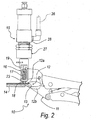
- a nailing machine according to the invention is generally designated by the reference numeral 10.
- the nailing machine 10 comprises a clamp body 11, which forms a grip vise 12 for a first portion 13 of material to be nailed, such as for example a flap of hide to be fixed to a second portion 14 of material, such as a mid-sole (for example made of leather).
- the grip vise 12 is composed of an upper jaw 12a and a lower jaw 12b.
- the automatic nailing means 15 comprise a device 16 for positioning a nailing element 17, such as for example a nail, in the nailing position.
- the device 16 is rigidly coupled at its end to the grip vise 12 and in particular is fixed rigidly to the upper jaw 12a, and is provided with an opening 18 for the exit of the nailing elements 17 at the region in front of the grip vise 12.
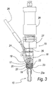
- the device 16 is constituted by a box-like body 19, inside which there is a channel 20 that passes through the entire box-like body 19 and leads outside through the opening 18 at the region in front of the grip vise 12.
- the channel 20 is arranged substantially at right angles to the nailing plane.
- Means 21 for closing and keeping in position (before the nailing step) the nailing element 17 are associated with the opening 18.
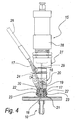
- the means 21 for closing and keeping in position are constituted for example by two mutually opposite flaps 22, which are pivoted to the box-like body 19 and, when closed, prevent the nailing element 17 from escaping through the opening 18.
- the flaps 22 have oppositely arranged L-shapes, are pivoted at the long end of the L-shape, and are in contact with their other end.
- An elastic element 23 is provided between the flaps 22 and keeps them in contact so as to close the opening 18.
- the elastic element 23 is constituted by an elastic ring, which surrounds, on a plane that is perpendicular to the nailing direction, the mutually opposite flaps 22, keeping them closed in contact with each other; such elastic ring is arranged in corresponding slots 23a formed in the oppositely arranged flaps 22.
- the flaps 22 are moved back so as to close by the elastic element 23.
- the nailing element 17 is thus accommodated in the channel 20 at the opening 18.
- the channel 20 Upstream of the portion for accommodating the nailing element 17, the channel 20 splits laterally into a channel 24 for feeding nailing elements 17, which is orientated substantially so as to converge with respect to the nailing direction.
- the positioning device 16 is associated with a magazine 25 of nailing elements 17, as described in greater detail hereinafter, by means of a flexible duct 26 for connection to the feeding channel 24.
- the automatic nailing means 15 comprise, in addition to the positioning device 16 for the nailing element 17, means 27 for pushing the nailing element toward the portions 13 and 14 of material to be nailed.
- the pusher means 27 are constituted, in this embodiment, by a pneumatic translational cylinder 28, which is fixed to the box-like body 19.
- the pneumatic translational cylinder 28 has an actuation stem 29 that is inserted so that it can slide within the channel 20, in a position upstream of the nailing element 17 with respect to the opening 18.
- the pusher means 27 are associated with a feeding system 30, which comprises a control 31 for operating the nailing machine 10 that is separate from the clamp body 11.
- the operating control 31 is of the pedal type.
- the feeding system 30 is constituted by a pneumatic system.
- the clamp body 11 and the automatic nailing means 15 are fixed to a vertical elastic support 32, such as for example a cable 33 that exits from a pulley with controlled elastic winding 34, of a per se known type, which allows to suspend the clamp body 11 at a preset working height.
- a vertical elastic support 32 such as for example a cable 33 that exits from a pulley with controlled elastic winding 34, of a per se known type, which allows to suspend the clamp body 11 at a preset working height.
- the pulley 34 with controlled elastic winding is fixed to the upper portion of a frame 35, on which the magazine 25 of nailing elements is further arranged.
- the pneumatic feeding system 30 is arranged mainly on the frame 35 and is connected to the pusher means 27 by means of first hoses 36.
- the pedal-type operation control 31 is also functionally connected by means of second hoses 37 to the feeding system 30.
- a working surface 38 is also formed on the frame 35.
- the magazine 25 of nailing elements is of a known type and comprises a trapdoor device (not shown in the figures), which allows correct orientation of the elements when they enter the flexible duct 26 for connection to the positioning device 16.
- the operator/user grips with one hand the clamp body 11, which grips, with its own jaws 12a and 12b, a flap of hide to be fixed for example to a leather mid-sole.
- the stem 29 pushes the nailing element 17, which is arranged at the opening 18 of the positioning device 16, which in turn pushes the flaps 22, which prevented it from exiting, and opens them.
- the nailing element 17 thus exits from the device 16 and is driven into the flap of hide and into the mid-sole.
- the elastic ring 23 moves the flaps 22 so that they close.
- the stem 29 rises, leaving in the channel 20 the space for a new nailing element 17, which descends by gravity from the magazine 25 by means of the flexible duct 26.
- the present invention provides a nailing machine, particularly for fixing portions of shoes, that allows to perform operations for mutually fixing portions of shoes or the like more rapidly and simply with respect to current standards.
- the materials employed may be any according to requirements and to the state of the art.
Landscapes
- Physics & Mathematics (AREA)
- Fluid Mechanics (AREA)
- Engineering & Computer Science (AREA)
- Mechanical Engineering (AREA)
- Life Sciences & Earth Sciences (AREA)
- Forests & Forestry (AREA)
- Portable Nailing Machines And Staplers (AREA)
- Dovetailed Work, And Nailing Machines And Stapling Machines For Wood (AREA)
- Footwear And Its Accessory, Manufacturing Method And Apparatuses (AREA)
- Motor Or Generator Cooling System (AREA)
- Duct Arrangements (AREA)
- Extrusion Moulding Of Plastics Or The Like (AREA)
Claims (11)
- Eine Nagelmaschine, insbesondere zur Befestigung von Teile von Schuhkomponenten, die einen Klemmkörper (11) umfasst, welcher von einem Benutzer mit einer Hand ergriffen werden kann und einen Schraubstock (12) zum Ergreifen mindestens eines ersten Abschnitts (13) von zu nagelndem Material bildet, wobei automatische Mittel (15) zum Annageln des mindestens einen ersten Abschnitts (13) von zu nagelndem Material an mindestens einen zweiten Abschnitt (14) von zu nagelndem Material an dem Schraubstock (12) bereitgestellt sind, wobei die automatischen Annagelungsmittel (15) starr mit dem Klemmkörper (11) gekoppelt sind, wobei die automatischen Annagelungsmittel (15) eine Vorrichtung (16) zum Positionieren eines Annagelungselements (17) in der Annagelungsposition und Mittel (27) zum Schieben des Annagelungselements (17) in die Richtung der Abschnitte (13, 14) von zu nagelndem Material umfassen, wobei ein Magazin (25) von Annagelungselementen (17) mit der Positioniervorrichtung (16) verknüpft ist, wobei die Schubmittel (27) mit einem Zuführsystem (30) verknüpft sind, welches eine Steuerung (31) zur Betätigung der Nagelmaschine (10) umfasst, die separat von dem Klemmkörper (11) ist, wobei die Betätigungssteuerung (31) vom Pedal-Typ ist.
- Die Nagelmaschine gemäß Anspruch 1, dadurch gekennzeichnet, dass das Zuführsystem (30) pneumatisch ist.
- Die Nagelmaschine gemäß einem oder mehreren der obigen Ansprüche, dadurch gekennzeichnet, dass der Schraubstock (12) aus einer oberen Backe (12a) und einer unteren Backe (12b) besteht, wobei die Positioniervorrichtung (16) starr mit der oberen Backe (12a) gekoppelt ist und die Positioniervorrichtung (16) weiter eine Austrittsöffnung (18) für das Annagelungselement (17) im vorderen Bereich des Schraubstocks (12) hat.
- Die Nagelmaschine gemäß Anspruch 3, dadurch gekennzeichnet, dass die Positioniervorrichtung (16) aus einem kastenartigen Körper (19) besteht, in dem sich ein Kanal (20) befindet, der durch den gesamten kastenartigen Körper (19) verläuft und außen durch die Öffnung (18) austritt, wobei das Annagelungselement (17) innerhalb des Kanals (20) untergebracht ist, wobei Mittel (21) zum Schließen und um das Vernagelungselement (17) in Position zu halten, mit der Öffnung (18) verknüpft sind.
- Die Nagelmaschine gemäß Anspruch 4, dadurch gekennzeichnet, dass die Mittel (21) zum Schließen und um das Annagelungselement (17) in Position zu halten, aus zwei einander gegenüber liegenden Klappen (22) bestehen, die drehgelenkig an dem kastenartigen Körper (19) angeordnet sind und die, wenn sie geschlossen sind, verhindern, dass das Annagelungselement (17) aus der Öffnung (18) austritt, wobei ein elastisches Rückführungselement (23) zum Verschließen der Öffnung (18) zwischen den Klappen (22) angebracht ist.
- Die Nagelmaschine gemäß Anspruch 5, dadurch gekennzeichnet, dass die Klappen (22) einander gegenüberliegende L-Formen haben, am langen Ende der L-Form drehgelenkig gelagert sind und über ihr anderes Ende in Kontakt stehen, wobei das elastische Element (23) aus einem elastischen Ring besteht, welcher die gegenüberliegenden Klappen (22) auf einer Ebene umgibt, die rechtwinklig zur Annagelungsrichtung ist, und sie in Kontakt miteinander geschlossen hält, wobei der elastische Ring in entsprechenden Schlitzen (23a) untergebracht ist, die in den einander gegenüberliegenden Klappen (22) gebildet sind.
- Die Nagelmaschine gemäß einem oder mehreren der obigen Ansprüche, dadurch gekennzeichnet, dass der Kanal (20), stromaufwärts von dem Abschnitt zur Aufnahme des Annagelungselements (17), seitlich in einen Kanal (24) zur Zuführung anderer Annagelungselemente (17) abzweigt, der so ausgerichtet ist, dass er im Wesentlichen mit der Annagelungsrichtung zusammenläuft.
- Die Nagelmaschine gemäß Anspruch 7, dadurch gekennzeichnet, dass die Positioniervorrichtung (16) mit dem Magazin (25) von Annagelungselementen durch eine flexible Leitung (26) zur Verbindung mit dem Zuführkanal (24) verbunden ist.
- Die Nagelmaschine gemäß einem oder mehreren der obigen Ansprüche, dadurch gekennzeichnet, dass die Schubmittel (27) aus einem pneumatischen Translationszylinder (28) bestehen, der an dem kastenartigen Körper (19) befestigt ist, wobei die Betätigungsstange (29) des Translationszylinders (28) so eingesetzt ist, dass sie in dem Kanal (20) gleiten kann, in einer Position stromaufwärts von dem Annagelungselement (17) im Verhältnis zu der Öffnung (18).
- Die Nagelmaschine gemäß einem oder mehreren der obigen Ansprüche, dadurch gekennzeichnet, dass der Klemmkörper (11) und die automatischen Annagelungsmittel (15) an einem vertikalen elastischen Träger (32) befestigt sind, der wiederum am oberen Abschnitt eines Rahmens (35) befestigt ist, an dem weiter das Magazin (25) von Annagelungselementen angeordnet ist.
- Die Nagelmaschine gemäß Anspruch 12, dadurch gekennzeichnet, dass das Zuführsystem (30) hauptsächlich an dem Rahmen (35) angeordnet und durch erste Schläuche (36) mit den Schubmitteln (27) verbunden ist.
Priority Applications (1)
| Application Number | Priority Date | Filing Date | Title |
|---|---|---|---|
| PL04017863T PL1504849T3 (pl) | 2003-08-07 | 2004-07-28 | Maszyna do wbijania gwoździ, zwłaszcza do mocowania części butów |
Applications Claiming Priority (2)
| Application Number | Priority Date | Filing Date | Title |
|---|---|---|---|
| IT000182A ITPD20030182A1 (it) | 2003-08-07 | 2003-08-07 | Macchina inchiodatrice, particolarmente |
| ITPD20030182 | 2003-08-07 |
Publications (2)
| Publication Number | Publication Date |
|---|---|
| EP1504849A1 EP1504849A1 (de) | 2005-02-09 |
| EP1504849B1 true EP1504849B1 (de) | 2009-03-04 |
Family
ID=33548874
Family Applications (1)
| Application Number | Title | Priority Date | Filing Date |
|---|---|---|---|
| EP04017863A Expired - Lifetime EP1504849B1 (de) | 2003-08-07 | 2004-07-28 | Nagelmaschine, insbesondere zur Befestigung von Schuhkomponenten |
Country Status (6)
| Country | Link |
|---|---|
| EP (1) | EP1504849B1 (de) |
| AT (1) | ATE424281T1 (de) |
| DE (1) | DE602004019731D1 (de) |
| ES (1) | ES2324410T3 (de) |
| IT (1) | ITPD20030182A1 (de) |
| PL (1) | PL1504849T3 (de) |
Families Citing this family (2)
| Publication number | Priority date | Publication date | Assignee | Title |
|---|---|---|---|---|
| ES2330908B1 (es) * | 2007-05-03 | 2010-09-17 | Fernando Javier Guillermo Lorenzo Gonzalez (50%) | Maquina automatica para el recambio de tapas de calzado. |
| ITUB20160167A1 (it) * | 2016-02-03 | 2017-08-03 | Delta Chiodatrici E Impianti Per Costruzione Pallet S R L | Pinza chiodatrice, macchina chiodatrice e metodo di chiodatura |
Family Cites Families (6)
| Publication number | Priority date | Publication date | Assignee | Title |
|---|---|---|---|---|
| GB190723042A (en) * | 1907-10-18 | 1908-10-19 | Harold Williamson Lake | Improvements in or relating to Machines for Lasting Boots and Shoes. |
| GB191018091A (en) * | 1909-04-05 | 1910-12-01 | George Goddu | Improvements in or relating to Machines for Inserting Fasteners. |
| US1421655A (en) * | 1920-09-25 | 1922-07-04 | Charles F Ziegler | Sole tacker |
| US1542946A (en) * | 1923-09-14 | 1925-06-23 | Oscar L Lawson | Tack-driving device |
| US2048857A (en) * | 1935-05-29 | 1936-07-28 | Ferrini Guiseppe | Half-soling pincers and nailer |
| FR2101471A5 (de) * | 1971-06-08 | 1972-03-31 | Bastin Jean Pierre |
-
2003
- 2003-08-07 IT IT000182A patent/ITPD20030182A1/it unknown
-
2004
- 2004-07-28 EP EP04017863A patent/EP1504849B1/de not_active Expired - Lifetime
- 2004-07-28 ES ES04017863T patent/ES2324410T3/es not_active Expired - Lifetime
- 2004-07-28 AT AT04017863T patent/ATE424281T1/de not_active IP Right Cessation
- 2004-07-28 DE DE602004019731T patent/DE602004019731D1/de not_active Expired - Fee Related
- 2004-07-28 PL PL04017863T patent/PL1504849T3/pl unknown
Also Published As
| Publication number | Publication date |
|---|---|
| EP1504849A1 (de) | 2005-02-09 |
| ES2324410T3 (es) | 2009-08-06 |
| ITPD20030182A1 (it) | 2005-02-08 |
| ATE424281T1 (de) | 2009-03-15 |
| PL1504849T3 (pl) | 2009-08-31 |
| DE602004019731D1 (de) | 2009-04-16 |
Similar Documents
| Publication | Publication Date | Title |
|---|---|---|
| EP1504849A1 (de) | Nagelmaschine, insbesondere zur Befestigung von Schuhkomponenten | |
| US2783468A (en) | Automatic-feed nailing machine | |
| US4657166A (en) | Pneumatically operated nailing machine | |
| US3743161A (en) | Fastener applying device | |
| US241524A (en) | Mechanism for lasting boots and shoes | |
| US1895457A (en) | Fastening inserting mechanism | |
| US206019A (en) | Improvement in hand lasting-tools for boots and shoes | |
| US1033945A (en) | Machine for use in the manufacture of boots and shoes. | |
| US312335A (en) | dancel | |
| US463292A (en) | And edward | |
| CN115998051B (zh) | 一种高效鞋跟打钉装置 | |
| US279427A (en) | perry | |
| US5983697A (en) | Clip pliers | |
| US311851A (en) | Gobdon mckay | |
| US183919A (en) | Improvement in lasting-machines for boots and shoes | |
| US236220A (en) | Lasting device | |
| US1082488A (en) | Pulling-over machine. | |
| US1030777A (en) | Tack-pulling machine. | |
| US2428803A (en) | Manufacture of footwear | |
| US1257689A (en) | Lasting-machine. | |
| US189850A (en) | Improvement in nailing-machines for boots and shoes | |
| US311850A (en) | Gordon mckay | |
| JP2550004B2 (ja) | ラベルハンガーマガジンの打込み装置 | |
| US629553A (en) | Lasting-machine. | |
| GB190911389A (en) | Improved Lasting Machine. |
Legal Events
| Date | Code | Title | Description |
|---|---|---|---|
| PUAI | Public reference made under article 153(3) epc to a published international application that has entered the european phase |
Free format text: ORIGINAL CODE: 0009012 |
|
| AK | Designated contracting states |
Kind code of ref document: A1 Designated state(s): AT BE BG CH CY CZ DE DK EE ES FI FR GB GR HU IE IT LI LU MC NL PL PT RO SE SI SK TR |
|
| AX | Request for extension of the european patent |
Extension state: AL HR LT LV MK |
|
| 17P | Request for examination filed |
Effective date: 20050506 |
|
| AKX | Designation fees paid |
Designated state(s): AT BE BG CH CY CZ DE DK EE ES FI FR GB GR HU IE IT LI LU MC NL PL PT RO SE SI SK TR |
|
| GRAP | Despatch of communication of intention to grant a patent |
Free format text: ORIGINAL CODE: EPIDOSNIGR1 |
|
| GRAS | Grant fee paid |
Free format text: ORIGINAL CODE: EPIDOSNIGR3 |
|
| GRAA | (expected) grant |
Free format text: ORIGINAL CODE: 0009210 |
|
| AK | Designated contracting states |
Kind code of ref document: B1 Designated state(s): AT BE BG CH CY CZ DE DK EE ES FI FR GB GR HU IE IT LI LU MC NL PL PT RO SE SI SK TR |
|
| REG | Reference to a national code |
Ref country code: GB Ref legal event code: FG4D |
|
| REG | Reference to a national code |
Ref country code: CH Ref legal event code: EP |
|
| REG | Reference to a national code |
Ref country code: IE Ref legal event code: FG4D |
|
| REF | Corresponds to: |
Ref document number: 602004019731 Country of ref document: DE Date of ref document: 20090416 Kind code of ref document: P |
|
| REG | Reference to a national code |
Ref country code: RO Ref legal event code: EPE |
|
| PG25 | Lapsed in a contracting state [announced via postgrant information from national office to epo] |
Ref country code: SI Free format text: LAPSE BECAUSE OF FAILURE TO SUBMIT A TRANSLATION OF THE DESCRIPTION OR TO PAY THE FEE WITHIN THE PRESCRIBED TIME-LIMIT Effective date: 20090304 Ref country code: NL Free format text: LAPSE BECAUSE OF FAILURE TO SUBMIT A TRANSLATION OF THE DESCRIPTION OR TO PAY THE FEE WITHIN THE PRESCRIBED TIME-LIMIT Effective date: 20090304 Ref country code: FI Free format text: LAPSE BECAUSE OF FAILURE TO SUBMIT A TRANSLATION OF THE DESCRIPTION OR TO PAY THE FEE WITHIN THE PRESCRIBED TIME-LIMIT Effective date: 20090304 |
|
| NLV1 | Nl: lapsed or annulled due to failure to fulfill the requirements of art. 29p and 29m of the patents act | ||
| REG | Reference to a national code |
Ref country code: ES Ref legal event code: FG2A Ref document number: 2324410 Country of ref document: ES Kind code of ref document: T3 |
|
| PG25 | Lapsed in a contracting state [announced via postgrant information from national office to epo] |
Ref country code: AT Free format text: LAPSE BECAUSE OF FAILURE TO SUBMIT A TRANSLATION OF THE DESCRIPTION OR TO PAY THE FEE WITHIN THE PRESCRIBED TIME-LIMIT Effective date: 20090304 Ref country code: SE Free format text: LAPSE BECAUSE OF FAILURE TO SUBMIT A TRANSLATION OF THE DESCRIPTION OR TO PAY THE FEE WITHIN THE PRESCRIBED TIME-LIMIT Effective date: 20090604 |
|
| REG | Reference to a national code |
Ref country code: PL Ref legal event code: T3 |
|
| PG25 | Lapsed in a contracting state [announced via postgrant information from national office to epo] |
Ref country code: BE Free format text: LAPSE BECAUSE OF FAILURE TO SUBMIT A TRANSLATION OF THE DESCRIPTION OR TO PAY THE FEE WITHIN THE PRESCRIBED TIME-LIMIT Effective date: 20090304 |
|
| PG25 | Lapsed in a contracting state [announced via postgrant information from national office to epo] |
Ref country code: CZ Free format text: LAPSE BECAUSE OF FAILURE TO SUBMIT A TRANSLATION OF THE DESCRIPTION OR TO PAY THE FEE WITHIN THE PRESCRIBED TIME-LIMIT Effective date: 20090304 Ref country code: PT Free format text: LAPSE BECAUSE OF FAILURE TO SUBMIT A TRANSLATION OF THE DESCRIPTION OR TO PAY THE FEE WITHIN THE PRESCRIBED TIME-LIMIT Effective date: 20090819 Ref country code: EE Free format text: LAPSE BECAUSE OF FAILURE TO SUBMIT A TRANSLATION OF THE DESCRIPTION OR TO PAY THE FEE WITHIN THE PRESCRIBED TIME-LIMIT Effective date: 20090304 |
|
| PG25 | Lapsed in a contracting state [announced via postgrant information from national office to epo] |
Ref country code: SK Free format text: LAPSE BECAUSE OF FAILURE TO SUBMIT A TRANSLATION OF THE DESCRIPTION OR TO PAY THE FEE WITHIN THE PRESCRIBED TIME-LIMIT Effective date: 20090304 |
|
| PLBE | No opposition filed within time limit |
Free format text: ORIGINAL CODE: 0009261 |
|
| STAA | Information on the status of an ep patent application or granted ep patent |
Free format text: STATUS: NO OPPOSITION FILED WITHIN TIME LIMIT |
|
| PG25 | Lapsed in a contracting state [announced via postgrant information from national office to epo] |
Ref country code: BG Free format text: LAPSE BECAUSE OF FAILURE TO SUBMIT A TRANSLATION OF THE DESCRIPTION OR TO PAY THE FEE WITHIN THE PRESCRIBED TIME-LIMIT Effective date: 20090604 Ref country code: DK Free format text: LAPSE BECAUSE OF FAILURE TO SUBMIT A TRANSLATION OF THE DESCRIPTION OR TO PAY THE FEE WITHIN THE PRESCRIBED TIME-LIMIT Effective date: 20090304 |
|
| 26N | No opposition filed |
Effective date: 20091207 |
|
| PG25 | Lapsed in a contracting state [announced via postgrant information from national office to epo] |
Ref country code: MC Free format text: LAPSE BECAUSE OF NON-PAYMENT OF DUE FEES Effective date: 20090731 |
|
| REG | Reference to a national code |
Ref country code: CH Ref legal event code: PL |
|
| GBPC | Gb: european patent ceased through non-payment of renewal fee |
Effective date: 20090728 |
|
| REG | Reference to a national code |
Ref country code: FR Ref legal event code: ST Effective date: 20100331 |
|
| REG | Reference to a national code |
Ref country code: IE Ref legal event code: MM4A |
|
| PG25 | Lapsed in a contracting state [announced via postgrant information from national office to epo] |
Ref country code: LI Free format text: LAPSE BECAUSE OF NON-PAYMENT OF DUE FEES Effective date: 20090731 Ref country code: RO Free format text: LAPSE BECAUSE OF NON-PAYMENT OF DUE FEES Effective date: 20090304 Ref country code: FR Free format text: LAPSE BECAUSE OF NON-PAYMENT OF DUE FEES Effective date: 20090731 Ref country code: CH Free format text: LAPSE BECAUSE OF NON-PAYMENT OF DUE FEES Effective date: 20090731 |
|
| PG25 | Lapsed in a contracting state [announced via postgrant information from national office to epo] |
Ref country code: GB Free format text: LAPSE BECAUSE OF NON-PAYMENT OF DUE FEES Effective date: 20090728 |
|
| PG25 | Lapsed in a contracting state [announced via postgrant information from national office to epo] |
Ref country code: DE Free format text: LAPSE BECAUSE OF NON-PAYMENT OF DUE FEES Effective date: 20100202 |
|
| PG25 | Lapsed in a contracting state [announced via postgrant information from national office to epo] |
Ref country code: IE Free format text: LAPSE BECAUSE OF NON-PAYMENT OF DUE FEES Effective date: 20090728 |
|
| REG | Reference to a national code |
Ref country code: ES Ref legal event code: FD2A Effective date: 20090729 |
|
| PG25 | Lapsed in a contracting state [announced via postgrant information from national office to epo] |
Ref country code: ES Free format text: LAPSE BECAUSE OF NON-PAYMENT OF DUE FEES Effective date: 20090729 Ref country code: GR Free format text: LAPSE BECAUSE OF FAILURE TO SUBMIT A TRANSLATION OF THE DESCRIPTION OR TO PAY THE FEE WITHIN THE PRESCRIBED TIME-LIMIT Effective date: 20090605 |
|
| PG25 | Lapsed in a contracting state [announced via postgrant information from national office to epo] |
Ref country code: LU Free format text: LAPSE BECAUSE OF NON-PAYMENT OF DUE FEES Effective date: 20090728 |
|
| PG25 | Lapsed in a contracting state [announced via postgrant information from national office to epo] |
Ref country code: HU Free format text: LAPSE BECAUSE OF FAILURE TO SUBMIT A TRANSLATION OF THE DESCRIPTION OR TO PAY THE FEE WITHIN THE PRESCRIBED TIME-LIMIT Effective date: 20090905 |
|
| PG25 | Lapsed in a contracting state [announced via postgrant information from national office to epo] |
Ref country code: PL Free format text: LAPSE BECAUSE OF NON-PAYMENT OF DUE FEES Effective date: 20090728 |
|
| REG | Reference to a national code |
Ref country code: PL Ref legal event code: LAPE |
|
| PG25 | Lapsed in a contracting state [announced via postgrant information from national office to epo] |
Ref country code: CY Free format text: LAPSE BECAUSE OF FAILURE TO SUBMIT A TRANSLATION OF THE DESCRIPTION OR TO PAY THE FEE WITHIN THE PRESCRIBED TIME-LIMIT Effective date: 20090304 |
|
| PG25 | Lapsed in a contracting state [announced via postgrant information from national office to epo] |
Ref country code: TR Free format text: LAPSE BECAUSE OF FAILURE TO SUBMIT A TRANSLATION OF THE DESCRIPTION OR TO PAY THE FEE WITHIN THE PRESCRIBED TIME-LIMIT Effective date: 20090304 |
|
| PGFP | Annual fee paid to national office [announced via postgrant information from national office to epo] |
Ref country code: IT Payment date: 20190514 Year of fee payment: 16 |
|
| PG25 | Lapsed in a contracting state [announced via postgrant information from national office to epo] |
Ref country code: IT Free format text: LAPSE BECAUSE OF NON-PAYMENT OF DUE FEES Effective date: 20200728 |