EP1504702A1 - Elektrisch beheizbares Kochgeschirr und Verfahren zu dessen Montage - Google Patents
Elektrisch beheizbares Kochgeschirr und Verfahren zu dessen Montage Download PDFInfo
- Publication number
- EP1504702A1 EP1504702A1 EP04015144A EP04015144A EP1504702A1 EP 1504702 A1 EP1504702 A1 EP 1504702A1 EP 04015144 A EP04015144 A EP 04015144A EP 04015144 A EP04015144 A EP 04015144A EP 1504702 A1 EP1504702 A1 EP 1504702A1
- Authority
- EP
- European Patent Office
- Prior art keywords
- cooking vessel
- cover ring
- cookware
- vessel
- cookware according
- Prior art date
- Legal status (The legal status is an assumption and is not a legal conclusion. Google has not performed a legal analysis and makes no representation as to the accuracy of the status listed.)
- Granted
Links
- 238000000034 method Methods 0.000 title claims abstract description 8
- 238000010411 cooking Methods 0.000 claims abstract description 50
- 238000010438 heat treatment Methods 0.000 claims description 9
- 229910052751 metal Inorganic materials 0.000 claims description 5
- 239000002184 metal Substances 0.000 claims description 5
- 229910001220 stainless steel Inorganic materials 0.000 claims description 4
- 239000010935 stainless steel Substances 0.000 claims description 4
- 238000007789 sealing Methods 0.000 claims description 2
- 229910052782 aluminium Inorganic materials 0.000 description 3
- XAGFODPZIPBFFR-UHFFFAOYSA-N aluminium Chemical compound [Al] XAGFODPZIPBFFR-UHFFFAOYSA-N 0.000 description 3
- 238000005452 bending Methods 0.000 description 2
- 239000007788 liquid Substances 0.000 description 2
- 230000003287 optical effect Effects 0.000 description 2
- 230000007704 transition Effects 0.000 description 2
- 238000010792 warming Methods 0.000 description 2
- 206010047571 Visual impairment Diseases 0.000 description 1
- 230000001419 dependent effect Effects 0.000 description 1
- 238000011161 development Methods 0.000 description 1
- 230000018109 developmental process Effects 0.000 description 1
- 239000000463 material Substances 0.000 description 1
- 230000002093 peripheral effect Effects 0.000 description 1
- 230000000284 resting effect Effects 0.000 description 1
- 208000029257 vision disease Diseases 0.000 description 1
- 230000004393 visual impairment Effects 0.000 description 1
Images

Classifications
-
- A—HUMAN NECESSITIES
- A47—FURNITURE; DOMESTIC ARTICLES OR APPLIANCES; COFFEE MILLS; SPICE MILLS; SUCTION CLEANERS IN GENERAL
- A47J—KITCHEN EQUIPMENT; COFFEE MILLS; SPICE MILLS; APPARATUS FOR MAKING BEVERAGES
- A47J27/00—Cooking-vessels
- A47J27/21—Water-boiling vessels, e.g. kettles
- A47J27/21166—Constructional details or accessories
-
- A—HUMAN NECESSITIES
- A47—FURNITURE; DOMESTIC ARTICLES OR APPLIANCES; COFFEE MILLS; SPICE MILLS; SUCTION CLEANERS IN GENERAL
- A47J—KITCHEN EQUIPMENT; COFFEE MILLS; SPICE MILLS; APPARATUS FOR MAKING BEVERAGES
- A47J27/00—Cooking-vessels
- A47J27/21—Water-boiling vessels, e.g. kettles
- A47J27/21008—Water-boiling vessels, e.g. kettles electrically heated
- A47J27/21041—Water-boiling vessels, e.g. kettles electrically heated with heating elements arranged outside the water vessel
Definitions
- the present invention relates to an electrically heated cookware according to Preamble of claim 1 and a method for mounting an electrical Heatable cookware according to the preamble of claim 12.
- connection of the cooking vessel to the bottom of the vessel should during the operation of the Cookware exercise the lowest possible bending force on the pot to damage For example, due to stress cracks on the pot to prevent.
- the cover ring should even at the service temperature of the pot no exercise force on the pot must However, for optical reasons be concentric aligned to the pot and safely this be held.
- the present invention is based on the object, an electrically heatable Cookware with an externally attached cover ring to provide, wherein this is held reliably and without pressure or Kraftbeierschlagung to the pot.
- an electrically heatable cookware it is provided that at a lower portion of an outer circumferential surface, a cover ring is attached, the There is frictionally fixed there by means of at least one elastic element.
- the elastic element may in particular as a tongue-like rubber element o. The like. be formed, which passes through a recess in the wall of the cooking vessel protrudes and that at least partially compressed when sliding the cover. Due to the elastic elements, which consist of recesses on the lateral surface of the Can protrude jug, additionally attached to the pot cover ring held reliably and without applying force on the lateral surface of the pot become. Even with an operational thermal expansion of the pot, the elastic elements advantageously provide for a path compensation, by compress without any additional force being applied to the jug.
- the elastic element or the elastic elements can be arranged on a ring be. However, the elastic elements can also be used as individual components be formed, which are inserted at the intended positions.
- the cover may in particular of sheet metal, for example. From stainless steel or Aluminum sheet, which has a much smaller thermal expansion coefficient has as the cooking vessel made of plastic. The between this and the metal ring arranged elastic elements can compensate for a stronger Warming the vessel wall, without any significant on this Force component is exercised.
- the cover ring may optionally be a one-piece, closed ring. However, it is also possible is a variant in which the cover ring is an open ring, the at one Junction is held together by appropriate means.
- the cover ring may optionally be formed so that it is part of a support foot of the Cookware is. Furthermore, it may be advantageous if on the outer circumferential surface of the cooking vessel a paragraph is provided, which has a flush transition between the Outside surfaces of the cover and the cooking vessel allows. The paragraph forms at the same time an upper stop for the cover, against which this when resting of the cooking vessel is pressed.
- a method for mounting the electric cookware according to the invention can after installing a heater and possibly one of them separate Bottom of the cover ring attached to the outer surface of the cooking vessel be, wherein the elastic elements are compressed, thereby thereby the Abeckring is held securely.
- the elastic elements are compressed, thereby thereby the Abeckring is held securely.
- the heater provide the elastic Elements for a compensation of the thermal expansion and thus prevent one undesirable radial force component on the vessel wall due to the relatively rigid Cover ring.
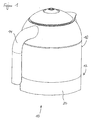
- FIG. 1 shows an electrically heated cookware.
- This includes a cooking vessel 10 in the form of a jug made of plastic, in which in a lower area 12 an electrically operable heater is used, the can be connected in particular by means of a vessel bottom with the cooking vessel.
- the Arrangement of the heater and the vessel bottom is described below with reference to Detail sections of Figures 2 to 4 explained in more detail.
- the cooking vessel 10 has a handle 14, which is attached to the outer circumferential surface 16 and for handling the Cooking vessel 10, in particular for pouring a liquid heated therein.
- a cover ring 20 is provided in the lower region 12, which may be part of a Can be Gefäßfußes and preferably from a metal sheet, for example. From Aluminum or stainless steel sheet exists.
- the cover ring 20 closes in the shown Embodiment flush with the outer circumferential surface 16 of the cooking vessel 10 from.
- Of the Cover ring 20 is preferably such with the outer circumferential surface 16 of the cooking vessel 10 connected, that he in a warming-related expansion of the cooking vessel 10th in the area of the heater no radial force exerted on the cooking vessel 10, which could lead to unwanted damage or visual impairment.
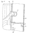
- FIG. 2 shows a schematic detail view of the attachment of the heating device 30 on an inner circumferential surface 18 of the cooking vessel 10.
- the heating device 30 is at her outer circumference by means of an elastic ring 32 on the inner circumferential surface 18 of the Cooking vessel 10 attached.
- the elastic ring 32 has two radially projecting Slats 34, whose outer diameter is greater than the inner diameter the inner circumferential surface 18 of the cooking vessel 10. Due to the elastic deformability the fins 34 bend this when inserting the heater 30 from below in the cooking vessel 10 in the manner shown in Figure 2 downwards, so that a reliable sealing of the internal volume of the cooking vessel 10 against the escape of Liquid is guaranteed.
- the ring 32 provides for a fixation of Heating device 30.
- first recesses 22nd provided in the wall 15 of the cooking vessel 10 , which serve to engage locking hooks 40 of a vessel bottom 38, so that the vessel bottom 38 can be firmly connected to the cooking vessel 10 and thereby simultaneously forms a lower stop for the heater 30.
- the Vessel bottom 38 are also connected to the heater 30, for example by a screw connection.
- the vessel bottom 38 is not shown from below set and by means of engaging in the recesses 22 snap hook 40 solvable attached.
- the detail section of Figure 3 shows a in a recess 22 of the wall 15th latched latch hook 40 of the vessel bottom 38.
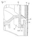
- the vessel bottom 38 has at his upper edge, which adjoins the lower edge of the wall 15, a series of additional recesses 42 on each of which tongue-shaped sections elastic elements 44 protrude.
- the protruding from the recesses 42 sections of the elastic elements 44 can optionally be attached to a continuous, closed ring 46, which in a corresponding annular receptacle 48 of the vessel bottom 38 is inserted.
- the ring 46 would be shown cut in Figure 4 in this case.
- the elastic elements 44 may also be formed as separate parts, wherein a block-like section 50 fixed in the receptacle 48 and the tongue-like portion out through the Recesses 42 protrudes.
- the elastic elements 44 can also by recesses in the Project wall 15 of the cooking vessel through.
- the attachment can also be on others Way as shown, for example, by inserting the elastic elements 44th from the inside of the cooking vessel and by suitable fixation, for example. By Jamming in a suitably dimensioned clamping seat.
- a shoulder 24 may be provided, on which the upper edge of the Cover ring 20 can rest. In this way, a flush transition between the outer surfaces of the cover ring 20 and the wall 15 of the cooking vessel 10 achieved become. In addition, the shoulder 24 forms an upper stop when mounting the Cover ring 20 over which this can not be pushed out.
Landscapes
- Engineering & Computer Science (AREA)
- Food Science & Technology (AREA)
- Cookers (AREA)
Abstract
Description
- Figur 1
- ein erfindungsgemäßes elektrisch beheizbares Kochgeschirr in schematischer Darstellung,
- Figur 2
- eine perspektivische Detailansicht des Kochgeschirrs gemäß Figur 1,
- Figur 3
- eine weitere perspektivische Detailansicht des Kochgeschirrs und
- Figur 4
- ein am Kochgeschirr montiertes elastisches Element zur Fixierung eines äußeren Abdeckrings in schematischer Perspektivdarstellung.
Claims (15)
- Elektrisch beheizbares Kochgeschirr, umfassend ein Kochgefäß (10) aus Kunststoff mit einem Gefäßboden (38), der eine elektrische Heizeinrichtung (30) aufweist und der über ein ringförmiges Dichtelement (32) form- und/oder kraftschlüssig in einem unteren Bereich (12) einer Innenmantelfläche (18) des Kochgefäßes (10) gehalten ist, und einen äußeren Abdeckring (20), der im unteren Bereich (12) einer Außenmantelfläche (16) des Kochgefäßes (10) angeordnet ist, dadurch gekennzeichnet, dass der Abdeckring (20) mittels wenigstens eines elastischen Elements (44) reibschlüssig an der Außenmantelfläche (16) des Kochgefäßes (10) gehalten ist.
- Kochgeschirr nach Anspruch 1, dadurch gekennzeichnet, dass der Abdeckring (20) ungefähr auf Höhe des Gefäßbodens (38) angeordnet ist.
- Kochgeschirr nach Anspruch 1 oder 2, dadurch gekennzeichnet, dass das wenigstens eine elastische Element (44) zum Festhalten des Außenrings (20) durch Aussparungen (42) in der Wandung (15) des Kochgefäßes (10) bzw. des Gefäßbodens (38) hindurch ragt.
- Kochgeschirr nach einem der voranstehenden Ansprüche, dadurch gekennzeichnet, dass wenigstens ein elastisches Element (44) bei aufgeschobenem Abdeckring (20) elastisch verformt ist.
- Kochgeschirr nach einem der voranstehenden Ansprüche, dadurch gekennzeichnet, dass das wenigstens eine elastische Element (44) für einen Ausgleich einer Wärmedehnung des Kochgefäßes (10) beim Betrieb der Heizeinrichtung (30) sorgt.
- Kochgeschirr nach einem der voranstehenden Ansprüche, dadurch gekennzeichnet, dass der Abdeckring (20) aus Metallblech besteht.
- Kochgeschirr nach einem der voranstehenden Ansprüche, dadurch gekennzeichnet, dass der Abdeckring (20) aus Edelstahlblech besteht.
- Kochgeschirr nach einem der voranstehenden Ansprüche, dadurch gekennzeichnet, dass der Abdeckring (20) ein geschlossener Ring ist.
- Kochgeschirr nach einem der voranstehenden Ansprüche, dadurch gekennzeichnet, dass ein unterer Abschnitt des Abdeckrings (20) das Kochgefäß (10) überragt und einen Auflagefuß für dieses bildet.
- Kochgeschirr nach einem der voranstehenden Ansprüche, dadurch gekennzeichnet, dass an der Außenmantelfläche (16) des Kochgefäßes (10) ein Absatz (24) vorgesehen ist, an den eine obere Kante des Abdeckrings (20) bündig anschließt.
- Kochgeschirr nach einem der voranstehenden Ansprüche, dadurch gekennzeichnet, dass die Außenmantelflächen (16) des oberen Bereichs des Kochgefäßes (10) und des Abdeckrings (20) miteinander fluchten.
- Verfahren zur Montage eines elektrisch beheizbaren Kochgeschirrs, bei dem eine elektrische Heizeinrichtung (30) und ein Gefäßboden (38) in eine offene Unterseite eines Kochgefäßes (10) aus Kunststoff eingesetzt und dort montiert werden, und bei dem anschließend ein äußerer Abdeckring (20) in einem unteren Bereich (12) einer Außenmantelfläche (16) des Kochgefäßes (10) angebracht wird, dadurch gekennzeichnet, dass der Abdeckring (20) mittels wenigstens eines elastischen Elements (44) reibschlüssig an der Außenmantelfläche (16) des Kochgefäßes (10) gehalten wird.
- Verfahren nach Anspruch 12, dadurch gekennzeichnet, dass wenigstens ein elastisches Element (44) durch Aufschieben des Abdeckrings (20) elastisch verformt wird.
- Verfahren nach Anspruch 12 oder 13, dadurch gekennzeichnet, dass das wenigstens eine elastische Element (44) für einen Ausgleich einer Wärmedehnung des Kochgefäßes (10) beim Betrieb der Heizeinrichtung (30) sorgt.
- Verfahren nach einem der Ansprüche 12 bis 14 zur Montage eines elektrisch beheizbaren Kochgeschirrs gemäß einem der Ansprüche 1 bis 11.
Applications Claiming Priority (2)
| Application Number | Priority Date | Filing Date | Title |
|---|---|---|---|
| DE10335822 | 2003-08-05 | ||
| DE10335822A DE10335822A1 (de) | 2003-08-05 | 2003-08-05 | Elektrisch beheizbares Kochgeschirr und Verfahren zu dessen Montage |
Publications (2)
| Publication Number | Publication Date |
|---|---|
| EP1504702A1 true EP1504702A1 (de) | 2005-02-09 |
| EP1504702B1 EP1504702B1 (de) | 2006-05-31 |
Family
ID=33547083
Family Applications (1)
| Application Number | Title | Priority Date | Filing Date |
|---|---|---|---|
| EP04015144A Expired - Lifetime EP1504702B1 (de) | 2003-08-05 | 2004-06-28 | Elektrisch beheizbares Kochgeschirr und Verfahren zu dessen Montage |
Country Status (4)
| Country | Link |
|---|---|
| EP (1) | EP1504702B1 (de) |
| CN (1) | CN100464683C (de) |
| AT (1) | ATE327706T1 (de) |
| DE (2) | DE10335822A1 (de) |
Citations (2)
| Publication number | Priority date | Publication date | Assignee | Title |
|---|---|---|---|---|
| US5908570A (en) * | 1996-05-14 | 1999-06-01 | Seb S.A. | Electric kettle with metal heater plate |
| GB2346540A (en) * | 1999-02-08 | 2000-08-16 | Otter Controls Ltd | Heating element engagement assembly for electrically heated vessels |
Family Cites Families (9)
| Publication number | Priority date | Publication date | Assignee | Title |
|---|---|---|---|---|
| DE7533076U (de) * | 1975-10-17 | 1976-02-26 | Rowenta-Werke Gmbh, 6050 Offenbach | Wasserkocher |
| FR2679751B1 (fr) * | 1991-07-30 | 1995-04-07 | Moulinex Sa | Appareil electrique de cuisson et son procede de fabrication. |
| CN1259881C (zh) * | 1997-10-07 | 2006-06-21 | 奥特控制有限公司 | 电加热容器的改进 |
| GB9808634D0 (en) * | 1998-04-24 | 1998-06-24 | Koninkl Philips Electronics Nv | Heating apparatus and heating element assembly method |
| GB2344506B (en) * | 1998-12-08 | 2002-10-02 | Otter Controls Ltd | Improvements relating to electrically heated vessels |
| DE19907133A1 (de) * | 1999-02-19 | 2000-08-24 | Beau Monde Ind Ltd | Flüssigkeitsbehälter, insbesondere Wasserkocher |
| FR2806283B1 (fr) * | 2000-03-17 | 2002-07-19 | Seb Sa | Bouilloire electrique a plaque metallique de chauffe |
| GB2363055B (en) * | 2000-06-05 | 2004-02-25 | Otter Controls Ltd | Improvements relating to the assembly of heating elements into liquid heating vessels |
| GB2363973A (en) * | 2000-06-29 | 2002-01-16 | Otter Controls Ltd | Securing planar heating element in liquid heating vessel |
-
2003
- 2003-08-05 DE DE10335822A patent/DE10335822A1/de not_active Withdrawn
-
2004
- 2004-06-28 AT AT04015144T patent/ATE327706T1/de not_active IP Right Cessation
- 2004-06-28 DE DE502004000653T patent/DE502004000653D1/de not_active Expired - Lifetime
- 2004-06-28 EP EP04015144A patent/EP1504702B1/de not_active Expired - Lifetime
- 2004-08-05 CN CNB2004100560245A patent/CN100464683C/zh not_active Expired - Fee Related
Patent Citations (2)
| Publication number | Priority date | Publication date | Assignee | Title |
|---|---|---|---|---|
| US5908570A (en) * | 1996-05-14 | 1999-06-01 | Seb S.A. | Electric kettle with metal heater plate |
| GB2346540A (en) * | 1999-02-08 | 2000-08-16 | Otter Controls Ltd | Heating element engagement assembly for electrically heated vessels |
Also Published As
| Publication number | Publication date |
|---|---|
| CN1589715A (zh) | 2005-03-09 |
| DE502004000653D1 (de) | 2006-07-06 |
| DE10335822A1 (de) | 2005-03-03 |
| CN100464683C (zh) | 2009-03-04 |
| EP1504702B1 (de) | 2006-05-31 |
| ATE327706T1 (de) | 2006-06-15 |
Similar Documents
| Publication | Publication Date | Title |
|---|---|---|
| DE69822525T2 (de) | Verbesserungen an elektrisch geheizten Kochgefässen | |
| EP0731898A1 (de) | Anordnung zur montage und halterung eines einbaukochfeldes | |
| DE102008008311B4 (de) | Ringelement und zugehöriger Deckel | |
| DE102016116975A1 (de) | Zubereitungsgefäß für eine elektromotorisch betriebene Küchenmaschine | |
| DE3871627T2 (de) | Deckel fuer dampfdruck-kochtoepfe. | |
| DE19703269C2 (de) | Halterung für eine Kochfläche | |
| EP1504702B1 (de) | Elektrisch beheizbares Kochgeschirr und Verfahren zu dessen Montage | |
| EP0072454A1 (de) | Elektrische Kochplatte mit einem sie umgebenden Einbauring | |
| DE19819732C1 (de) | Anordnung zur Befestigung eines atmosphärischen Gasbrenners an der Brenneröffnung einer Kochfläche aus Glas oder Glaskeramik sowie Kochfeld mit einer solchen Anordnung | |
| DE29701190U1 (de) | Elektroofen | |
| EP1851407B1 (de) | Vorrichtung zum befestigen in einer in einem trägerteil ausgebildeten trägerteilausnehmung | |
| EP1840911B1 (de) | Montageanordnung | |
| DD251496A5 (de) | Gargefaess | |
| WO2008138751A1 (de) | Kochfeld | |
| EP1504701B1 (de) | Elektrisch beheizbares Kochgeschirr und Verfahren zu dessen Montage | |
| EP1942780A1 (de) | Kochgefäss mit handgriff | |
| DE69401877T2 (de) | Flüssigkeitssammler für Kochmulde | |
| DE10335823A1 (de) | Elektrisch beheizbares Kochgeschirr und Verfahren zu dessen Montage | |
| EP0984258A3 (de) | Haltemittel zum Fixieren eines Drucksensors | |
| DE102008014688B4 (de) | Ölwanne sowie Verschlusselement für eine Ölwanne | |
| DE19906901A1 (de) | Backofentür mit einer Glasscheibe | |
| DE202004021166U1 (de) | Elektrisch beheizbares Kochgeschirr | |
| DE19906905A1 (de) | Backofentür | |
| EP2029308A1 (de) | Lötvorrichtung | |
| EP0700654B1 (de) | Elektrisch beheiztes Kochgeschirr und Verfahren zu seiner Herstellung |
Legal Events
| Date | Code | Title | Description |
|---|---|---|---|
| PUAI | Public reference made under article 153(3) epc to a published international application that has entered the european phase |
Free format text: ORIGINAL CODE: 0009012 |
|
| AK | Designated contracting states |
Kind code of ref document: A1 Designated state(s): AT BE BG CH CY CZ DE DK EE ES FI FR GB GR HU IE IT LI LU MC NL PL PT RO SE SI SK TR |
|
| AX | Request for extension of the european patent |
Extension state: AL HR LT LV MK |
|
| 17P | Request for examination filed |
Effective date: 20050809 |
|
| AKX | Designation fees paid |
Designated state(s): AT BE BG CH CY CZ DE DK EE ES FI FR GB GR HU IE IT LI LU MC NL PL PT RO SE SI SK TR |
|
| GRAP | Despatch of communication of intention to grant a patent |
Free format text: ORIGINAL CODE: EPIDOSNIGR1 |
|
| GRAS | Grant fee paid |
Free format text: ORIGINAL CODE: EPIDOSNIGR3 |
|
| GRAA | (expected) grant |
Free format text: ORIGINAL CODE: 0009210 |
|
| AK | Designated contracting states |
Kind code of ref document: B1 Designated state(s): AT BE BG CH CY CZ DE DK EE ES FI FR GB GR HU IE IT LI LU MC NL PL PT RO SE SI SK TR |
|
| PG25 | Lapsed in a contracting state [announced via postgrant information from national office to epo] |
Ref country code: IT Free format text: LAPSE BECAUSE OF FAILURE TO SUBMIT A TRANSLATION OF THE DESCRIPTION OR TO PAY THE FEE WITHIN THE PRESCRIBED TIME-LIMIT;WARNING: LAPSES OF ITALIAN PATENTS WITH EFFECTIVE DATE BEFORE 2007 MAY HAVE OCCURRED AT ANY TIME BEFORE 2007. THE CORRECT EFFECTIVE DATE MAY BE DIFFERENT FROM THE ONE RECORDED. Effective date: 20060531 Ref country code: CZ Free format text: LAPSE BECAUSE OF FAILURE TO SUBMIT A TRANSLATION OF THE DESCRIPTION OR TO PAY THE FEE WITHIN THE PRESCRIBED TIME-LIMIT Effective date: 20060531 Ref country code: PL Free format text: LAPSE BECAUSE OF FAILURE TO SUBMIT A TRANSLATION OF THE DESCRIPTION OR TO PAY THE FEE WITHIN THE PRESCRIBED TIME-LIMIT Effective date: 20060531 Ref country code: NL Free format text: LAPSE BECAUSE OF FAILURE TO SUBMIT A TRANSLATION OF THE DESCRIPTION OR TO PAY THE FEE WITHIN THE PRESCRIBED TIME-LIMIT Effective date: 20060531 Ref country code: SK Free format text: LAPSE BECAUSE OF FAILURE TO SUBMIT A TRANSLATION OF THE DESCRIPTION OR TO PAY THE FEE WITHIN THE PRESCRIBED TIME-LIMIT Effective date: 20060531 Ref country code: FI Free format text: LAPSE BECAUSE OF FAILURE TO SUBMIT A TRANSLATION OF THE DESCRIPTION OR TO PAY THE FEE WITHIN THE PRESCRIBED TIME-LIMIT Effective date: 20060531 Ref country code: RO Free format text: LAPSE BECAUSE OF FAILURE TO SUBMIT A TRANSLATION OF THE DESCRIPTION OR TO PAY THE FEE WITHIN THE PRESCRIBED TIME-LIMIT Effective date: 20060531 Ref country code: IE Free format text: LAPSE BECAUSE OF FAILURE TO SUBMIT A TRANSLATION OF THE DESCRIPTION OR TO PAY THE FEE WITHIN THE PRESCRIBED TIME-LIMIT Effective date: 20060531 Ref country code: SI Free format text: LAPSE BECAUSE OF FAILURE TO SUBMIT A TRANSLATION OF THE DESCRIPTION OR TO PAY THE FEE WITHIN THE PRESCRIBED TIME-LIMIT Effective date: 20060531 |
|
| REG | Reference to a national code |
Ref country code: GB Ref legal event code: FG4D Free format text: NOT ENGLISH Ref country code: CH Ref legal event code: EP |
|
| REG | Reference to a national code |
Ref country code: IE Ref legal event code: FG4D Free format text: LANGUAGE OF EP DOCUMENT: GERMAN |
|
| PG25 | Lapsed in a contracting state [announced via postgrant information from national office to epo] |
Ref country code: MC Free format text: LAPSE BECAUSE OF NON-PAYMENT OF DUE FEES Effective date: 20060630 Ref country code: BE Free format text: LAPSE BECAUSE OF NON-PAYMENT OF DUE FEES Effective date: 20060630 |
|
| REF | Corresponds to: |
Ref document number: 502004000653 Country of ref document: DE Date of ref document: 20060706 Kind code of ref document: P |
|
| GBT | Gb: translation of ep patent filed (gb section 77(6)(a)/1977) |
Effective date: 20060626 |
|
| PG25 | Lapsed in a contracting state [announced via postgrant information from national office to epo] |
Ref country code: SE Free format text: LAPSE BECAUSE OF FAILURE TO SUBMIT A TRANSLATION OF THE DESCRIPTION OR TO PAY THE FEE WITHIN THE PRESCRIBED TIME-LIMIT Effective date: 20060831 Ref country code: DK Free format text: LAPSE BECAUSE OF FAILURE TO SUBMIT A TRANSLATION OF THE DESCRIPTION OR TO PAY THE FEE WITHIN THE PRESCRIBED TIME-LIMIT Effective date: 20060831 |
|
| PG25 | Lapsed in a contracting state [announced via postgrant information from national office to epo] |
Ref country code: ES Free format text: LAPSE BECAUSE OF FAILURE TO SUBMIT A TRANSLATION OF THE DESCRIPTION OR TO PAY THE FEE WITHIN THE PRESCRIBED TIME-LIMIT Effective date: 20060911 |
|
| PG25 | Lapsed in a contracting state [announced via postgrant information from national office to epo] |
Ref country code: PT Free format text: LAPSE BECAUSE OF FAILURE TO SUBMIT A TRANSLATION OF THE DESCRIPTION OR TO PAY THE FEE WITHIN THE PRESCRIBED TIME-LIMIT Effective date: 20061031 |
|
| NLV1 | Nl: lapsed or annulled due to failure to fulfill the requirements of art. 29p and 29m of the patents act | ||
| ET | Fr: translation filed | ||
| REG | Reference to a national code |
Ref country code: IE Ref legal event code: FD4D |
|
| PLBE | No opposition filed within time limit |
Free format text: ORIGINAL CODE: 0009261 |
|
| STAA | Information on the status of an ep patent application or granted ep patent |
Free format text: STATUS: NO OPPOSITION FILED WITHIN TIME LIMIT |
|
| 26N | No opposition filed |
Effective date: 20070301 |
|
| PG25 | Lapsed in a contracting state [announced via postgrant information from national office to epo] |
Ref country code: AT Free format text: LAPSE BECAUSE OF NON-PAYMENT OF DUE FEES Effective date: 20060628 |
|
| BERE | Be: lapsed |
Owner name: BSH BOSCH UND SIEMENS HAUSGERATE G.M.B.H. Effective date: 20060630 |
|
| PG25 | Lapsed in a contracting state [announced via postgrant information from national office to epo] |
Ref country code: GR Free format text: LAPSE BECAUSE OF FAILURE TO SUBMIT A TRANSLATION OF THE DESCRIPTION OR TO PAY THE FEE WITHIN THE PRESCRIBED TIME-LIMIT Effective date: 20060901 |
|
| PG25 | Lapsed in a contracting state [announced via postgrant information from national office to epo] |
Ref country code: EE Free format text: LAPSE BECAUSE OF FAILURE TO SUBMIT A TRANSLATION OF THE DESCRIPTION OR TO PAY THE FEE WITHIN THE PRESCRIBED TIME-LIMIT Effective date: 20060531 Ref country code: BG Free format text: LAPSE BECAUSE OF FAILURE TO SUBMIT A TRANSLATION OF THE DESCRIPTION OR TO PAY THE FEE WITHIN THE PRESCRIBED TIME-LIMIT Effective date: 20060831 |
|
| PG25 | Lapsed in a contracting state [announced via postgrant information from national office to epo] |
Ref country code: TR Free format text: LAPSE BECAUSE OF FAILURE TO SUBMIT A TRANSLATION OF THE DESCRIPTION OR TO PAY THE FEE WITHIN THE PRESCRIBED TIME-LIMIT Effective date: 20060531 Ref country code: LU Free format text: LAPSE BECAUSE OF NON-PAYMENT OF DUE FEES Effective date: 20060628 Ref country code: HU Free format text: LAPSE BECAUSE OF FAILURE TO SUBMIT A TRANSLATION OF THE DESCRIPTION OR TO PAY THE FEE WITHIN THE PRESCRIBED TIME-LIMIT Effective date: 20061201 |
|
| PG25 | Lapsed in a contracting state [announced via postgrant information from national office to epo] |
Ref country code: CY Free format text: LAPSE BECAUSE OF FAILURE TO SUBMIT A TRANSLATION OF THE DESCRIPTION OR TO PAY THE FEE WITHIN THE PRESCRIBED TIME-LIMIT Effective date: 20060531 |
|
| REG | Reference to a national code |
Ref country code: CH Ref legal event code: PL |
|
| PG25 | Lapsed in a contracting state [announced via postgrant information from national office to epo] |
Ref country code: CH Free format text: LAPSE BECAUSE OF NON-PAYMENT OF DUE FEES Effective date: 20080630 Ref country code: LI Free format text: LAPSE BECAUSE OF NON-PAYMENT OF DUE FEES Effective date: 20080630 |
|
| REG | Reference to a national code |
Ref country code: DE Ref legal event code: R081 Ref document number: 502004000653 Country of ref document: DE Owner name: BSH HAUSGERAETE GMBH, DE Free format text: FORMER OWNER: BSH BOSCH UND SIEMENS HAUSGERAETE GMBH, 81739 MUENCHEN, DE Effective date: 20150407 |
|
| REG | Reference to a national code |
Ref country code: FR Ref legal event code: PLFP Year of fee payment: 12 |
|
| REG | Reference to a national code |
Ref country code: FR Ref legal event code: CD Owner name: BSH HAUSGERATE GMBH Effective date: 20151022 |
|
| REG | Reference to a national code |
Ref country code: FR Ref legal event code: PLFP Year of fee payment: 13 |
|
| REG | Reference to a national code |
Ref country code: FR Ref legal event code: PLFP Year of fee payment: 14 |
|
| REG | Reference to a national code |
Ref country code: FR Ref legal event code: PLFP Year of fee payment: 15 |
|
| PGFP | Annual fee paid to national office [announced via postgrant information from national office to epo] |
Ref country code: DE Payment date: 20180630 Year of fee payment: 15 |
|
| PGFP | Annual fee paid to national office [announced via postgrant information from national office to epo] |
Ref country code: FR Payment date: 20180625 Year of fee payment: 15 |
|
| PGFP | Annual fee paid to national office [announced via postgrant information from national office to epo] |
Ref country code: GB Payment date: 20180626 Year of fee payment: 15 |
|
| REG | Reference to a national code |
Ref country code: DE Ref legal event code: R119 Ref document number: 502004000653 Country of ref document: DE |
|
| GBPC | Gb: european patent ceased through non-payment of renewal fee |
Effective date: 20190628 |
|
| PG25 | Lapsed in a contracting state [announced via postgrant information from national office to epo] |
Ref country code: DE Free format text: LAPSE BECAUSE OF NON-PAYMENT OF DUE FEES Effective date: 20200101 Ref country code: GB Free format text: LAPSE BECAUSE OF NON-PAYMENT OF DUE FEES Effective date: 20190628 |
|
| PG25 | Lapsed in a contracting state [announced via postgrant information from national office to epo] |
Ref country code: FR Free format text: LAPSE BECAUSE OF NON-PAYMENT OF DUE FEES Effective date: 20190630 |